EP2853805A1 - Beleuchtungs- und/oder Lichtsignalisierungssystem für Kraftfahrzeug mit mehreren drehbaren Multifunktionsmodulen - Google Patents
Beleuchtungs- und/oder Lichtsignalisierungssystem für Kraftfahrzeug mit mehreren drehbaren Multifunktionsmodulen Download PDFInfo
- Publication number
- EP2853805A1 EP2853805A1 EP14187198.8A EP14187198A EP2853805A1 EP 2853805 A1 EP2853805 A1 EP 2853805A1 EP 14187198 A EP14187198 A EP 14187198A EP 2853805 A1 EP2853805 A1 EP 2853805A1
- Authority
- EP
- European Patent Office
- Prior art keywords
- lighting
- module
- signaling system
- signaling
- modules
- Prior art date
- Legal status (The legal status is an assumption and is not a legal conclusion. Google has not performed a legal analysis and makes no representation as to the accuracy of the status listed.)
- Withdrawn
Links
Images



Classifications
-
- F—MECHANICAL ENGINEERING; LIGHTING; HEATING; WEAPONS; BLASTING
- F21—LIGHTING
- F21S—NON-PORTABLE LIGHTING DEVICES; SYSTEMS THEREOF; VEHICLE LIGHTING DEVICES SPECIALLY ADAPTED FOR VEHICLE EXTERIORS
- F21S41/00—Illuminating devices specially adapted for vehicle exteriors, e.g. headlamps
- F21S41/60—Illuminating devices specially adapted for vehicle exteriors, e.g. headlamps characterised by a variable light distribution
- F21S41/67—Illuminating devices specially adapted for vehicle exteriors, e.g. headlamps characterised by a variable light distribution by acting on reflectors
- F21S41/675—Illuminating devices specially adapted for vehicle exteriors, e.g. headlamps characterised by a variable light distribution by acting on reflectors by moving reflectors
-
- F—MECHANICAL ENGINEERING; LIGHTING; HEATING; WEAPONS; BLASTING
- F21—LIGHTING
- F21S—NON-PORTABLE LIGHTING DEVICES; SYSTEMS THEREOF; VEHICLE LIGHTING DEVICES SPECIALLY ADAPTED FOR VEHICLE EXTERIORS
- F21S41/00—Illuminating devices specially adapted for vehicle exteriors, e.g. headlamps
- F21S41/10—Illuminating devices specially adapted for vehicle exteriors, e.g. headlamps characterised by the light source
- F21S41/14—Illuminating devices specially adapted for vehicle exteriors, e.g. headlamps characterised by the light source characterised by the type of light source
- F21S41/141—Light emitting diodes [LED]
- F21S41/147—Light emitting diodes [LED] the main emission direction of the LED being angled to the optical axis of the illuminating device
- F21S41/148—Light emitting diodes [LED] the main emission direction of the LED being angled to the optical axis of the illuminating device the main emission direction of the LED being perpendicular to the optical axis
-
- F—MECHANICAL ENGINEERING; LIGHTING; HEATING; WEAPONS; BLASTING
- F21—LIGHTING
- F21S—NON-PORTABLE LIGHTING DEVICES; SYSTEMS THEREOF; VEHICLE LIGHTING DEVICES SPECIALLY ADAPTED FOR VEHICLE EXTERIORS
- F21S41/00—Illuminating devices specially adapted for vehicle exteriors, e.g. headlamps
- F21S41/10—Illuminating devices specially adapted for vehicle exteriors, e.g. headlamps characterised by the light source
- F21S41/14—Illuminating devices specially adapted for vehicle exteriors, e.g. headlamps characterised by the light source characterised by the type of light source
- F21S41/141—Light emitting diodes [LED]
- F21S41/151—Light emitting diodes [LED] arranged in one or more lines
-
- F—MECHANICAL ENGINEERING; LIGHTING; HEATING; WEAPONS; BLASTING
- F21—LIGHTING
- F21S—NON-PORTABLE LIGHTING DEVICES; SYSTEMS THEREOF; VEHICLE LIGHTING DEVICES SPECIALLY ADAPTED FOR VEHICLE EXTERIORS
- F21S41/00—Illuminating devices specially adapted for vehicle exteriors, e.g. headlamps
- F21S41/20—Illuminating devices specially adapted for vehicle exteriors, e.g. headlamps characterised by refractors, transparent cover plates, light guides or filters
- F21S41/25—Projection lenses
- F21S41/26—Elongated lenses
-
- F—MECHANICAL ENGINEERING; LIGHTING; HEATING; WEAPONS; BLASTING
- F21—LIGHTING
- F21S—NON-PORTABLE LIGHTING DEVICES; SYSTEMS THEREOF; VEHICLE LIGHTING DEVICES SPECIALLY ADAPTED FOR VEHICLE EXTERIORS
- F21S41/00—Illuminating devices specially adapted for vehicle exteriors, e.g. headlamps
- F21S41/20—Illuminating devices specially adapted for vehicle exteriors, e.g. headlamps characterised by refractors, transparent cover plates, light guides or filters
- F21S41/25—Projection lenses
- F21S41/27—Thick lenses
-
- F—MECHANICAL ENGINEERING; LIGHTING; HEATING; WEAPONS; BLASTING
- F21—LIGHTING
- F21S—NON-PORTABLE LIGHTING DEVICES; SYSTEMS THEREOF; VEHICLE LIGHTING DEVICES SPECIALLY ADAPTED FOR VEHICLE EXTERIORS
- F21S41/00—Illuminating devices specially adapted for vehicle exteriors, e.g. headlamps
- F21S41/30—Illuminating devices specially adapted for vehicle exteriors, e.g. headlamps characterised by reflectors
- F21S41/32—Optical layout thereof
- F21S41/322—Optical layout thereof the reflector using total internal reflection
-
- F—MECHANICAL ENGINEERING; LIGHTING; HEATING; WEAPONS; BLASTING
- F21—LIGHTING
- F21S—NON-PORTABLE LIGHTING DEVICES; SYSTEMS THEREOF; VEHICLE LIGHTING DEVICES SPECIALLY ADAPTED FOR VEHICLE EXTERIORS
- F21S41/00—Illuminating devices specially adapted for vehicle exteriors, e.g. headlamps
- F21S41/60—Illuminating devices specially adapted for vehicle exteriors, e.g. headlamps characterised by a variable light distribution
- F21S41/63—Illuminating devices specially adapted for vehicle exteriors, e.g. headlamps characterised by a variable light distribution by acting on refractors, filters or transparent cover plates
- F21S41/635—Illuminating devices specially adapted for vehicle exteriors, e.g. headlamps characterised by a variable light distribution by acting on refractors, filters or transparent cover plates by moving refractors, filters or transparent cover plates
-
- F—MECHANICAL ENGINEERING; LIGHTING; HEATING; WEAPONS; BLASTING
- F21—LIGHTING
- F21S—NON-PORTABLE LIGHTING DEVICES; SYSTEMS THEREOF; VEHICLE LIGHTING DEVICES SPECIALLY ADAPTED FOR VEHICLE EXTERIORS
- F21S41/00—Illuminating devices specially adapted for vehicle exteriors, e.g. headlamps
- F21S41/60—Illuminating devices specially adapted for vehicle exteriors, e.g. headlamps characterised by a variable light distribution
- F21S41/65—Illuminating devices specially adapted for vehicle exteriors, e.g. headlamps characterised by a variable light distribution by acting on light sources
- F21S41/657—Illuminating devices specially adapted for vehicle exteriors, e.g. headlamps characterised by a variable light distribution by acting on light sources by moving light sources
Definitions
- the invention relates to the field of lighting and / or light signaling, in particular for a motor vehicle.
- the published patent document EP 2 280 215 A2 discloses a lighting device for a motor vehicle configured to generate an adaptive dynamic lighting beam.
- This beam is a road lighting beam (commonly called "High Beam” in English) with the particularity that it includes a lower illumination upper zone, this area being movable horizontally so as to correspond to a vehicle coming in the opposite direction.
- the device comprises a series of individually electro-luminescent light-emitting diode-type light sources that are optically coupled to form a lighting beam by adding beam segments produced by each of the light sources.
- This teaching is interesting in that it does not include any moving parts. However, it requires a large number of light sources. It also has limitations as to the characteristics of the beam produced.
- the object of the invention is to provide a lighting and / or light-signaling system which overcomes at least one of the drawbacks of the state of the art, more particularly of the state of the art mentioned above. More particularly, the invention aims to provide a lighting system and / or light signaling capable of generating a lighting beam and / or variable or adaptable light signaling.
- the invention relates to a lighting and / or signaling system, in particular for a motor vehicle, comprising a plurality of optical modules configured to produce beams combining in a main direction; remarkable in that at least one, preferably each, optical modules comprises at least two optical systems arranged on a rotatable support so as to be able to selectively orient each of the optical systems in the main direction.
- At least one, preferably each, of the optical systems comprises a lens with an input face, an output face and a reflective surface able to reflect towards the output face the rays coming from the entrance face.
- the or at least one of the lenses extends in a curved profile in a transverse plane, preferably generally perpendicular to the axis of rotation of the support.
- the entry face of the lens or lenses is generally transverse, preferably generally perpendicular to the axis of rotation of the support.
- the exit face of the lens or lenses forms a projecting rounded portion, able to bring closer, in a plane generally perpendicular to the axis of rotation, the rays issuing from the lens.
- the exit face of the lens or lenses has a rounded profile in a plane passing through the axis of rotation of the support, the exit face forming a convex surface.
- each of the optical systems comprises one or more specific light sources, said light sources of one or each of the modules being preferentially arranged on a platen common to said module.
- the light sources of one or each of the modules are electroluminescence diodes illuminating in a main direction generally parallel to the axis of rotation of the support.
- At least one of the light sources of the module or modules is arranged in such a way that its main illumination direction forms an angle of between 5 ° and 25 °, preferably between 10 ° and 20 °. , with the axis of rotation of the support.
- At least one of the light sources of the module or modules is colored and / or is covered with a colored filter.
- the system comprises a first module of which at least one, preferably each, optical systems is capable of forming a lighting beam whose width corresponds to that of a crossing lighting function.
- a second module at least one of the optical systems is capable of forming a narrower illumination beam and higher than that of the first module, corresponding to a road lighting function.
- the output face of the lens or lenses of the first module has a curved profile in a plane perpendicular to the axis of rotation of the support, the radius of curvature of said profile remaining constant in a range of tolerance of 10% over most of its length.
- the exit face of the lens or lenses of the second module has a curved profile in a plane perpendicular to the axis of rotation of the support, projecting from the lateral portions of the lens or lenses.
- each of the modules comprises a first optical system capable of forming a beam participating in the construction of a first lighting and / or signaling function and a second optical system capable of forming a participating beam.
- the first function being provided by the addition of the beams of the first systems of the modules and the second function being provided by the addition of the beams of the second systems of the modules .
- the lighting and / or signaling functions are selected from the following lighting and / or signaling functions for a motor vehicle: daytime running signal (DRL), lighting or dipped beam, lighting or high beam, change of direction indicator.
- DRL daytime running signal
- lighting or dipped beam lighting or high beam
- change of direction indicator change of direction indicator
- the measures of the invention are interesting in that they make it possible to produce a system that provides several lighting and / or signaling functions.
- the modules according to the invention can be made in a compact manner. Their accuracy can be very good, especially when the light sources of the same module are arranged on a common board, thus ensuring relative positioning exact.
- the presence of two modules with each two optical systems already allows for several combinations of beams.
- the presence of three modules with, each, three optical systems, as illustrated in figure 2 allows in particular to build at least three basic functions with variations.
- the figure 1 is a schematic representation of a lighting and / or light-signaling module for a motor vehicle, present in the lighting and / or light-signaling system according to the invention and illustrated in FIG. figure 2 .
- the module 2 essentially comprises several optical systems, in this case two optical systems 4 and 4 'disposed on either side of an axis of rotation 18.
- the optical systems 4 and 4' are arranged on a support 16 not detailed, this support being rotatable relative to a frame not shown around the axis of rotation 18.
- the axis of rotation is therefore preferably fixed relative to the frame and relative to the vehicle on which it is intended to be mounted .
- Each optical system 4 and 4 ' essentially comprises a lens 6 and a specific light source 8. More particularly, the lens 6 or 6 'comprises an input face 10 or 10' of the light, arranged opposite the light source 8 or 8 '.
- the latter is preferably of the electroluminescence diode type. It illuminates preferentially in a main direction generally parallel to the axis of rotation 18.
- the input face 10 or 10 ' is then transverse to the axis of rotation 18, preferably perpendicular to said axis.
- the reflecting face is preferably substantially flat. However, it may have a non-planar geometry, close to a geometry plane.
- the lens 6 or 6 ' also comprises an exit face 14 or 14'.
- the reflecting face 12 or 12 ' is configured to reflect to the output face 14 or 14' the rays from the light source 8 or 8 'via the input face.
- the configuration of the lens in particular the location of the light source and the geometry of the input face, the reflective face and the output face make it possible to produce beams with different characteristics. It can indeed be observed at the figure 1 that the right lens 6 produces a beam directed downwards with respect to the horizon, such as a beam of crossing lighting, that is to say at break, and that the lens 6 'left produces a more homogeneous beam in a vertical direction, which may correspond to a road lighting beam.
- the particular forms of the lenses will be detailed further in connection with the figures 3 , 8 and 12 .
- Rotational actuation means are then provided at the level of the support 16 in order to allow the angular positioning of the optical systems. Such means are well known to those skilled in the art and should not be detailed.
- the material of the lenses 6 and 6 ' is transparent, such as for example glass or plastic materials such as polycarbonate.
- each optical system 4 or 4 ' is preferably specific, that is to say fixed with respect to the corresponding lens 6 or 6'.
- the light sources 8 and 8 'of a module 2 can be arranged on a common support, in this case on a common plate 9, said plate being fixed to the rotary support 16.
- the light sources can be fixed individually to their optical system.
- a module to include only one light source common to the different optical systems. In this case, it is then fixed relative to the frame of the module, the optical systems being able to move in rotation with respect in particular to the light source.
- the light source common to all the optical systems of the module or specific to each optical system of the module may not be unique and include a set of point light sources forming an assimilable source to a single source.
- the means for rotating the support and the optical systems makes it possible to position the selected optical system in the desired lighting and / or light-signaling direction. In this case, it is desirable for the light source (s) of the inactive optical systems to be extinguished.
- the number of optical systems on each module 2 can vary: it can be two, three or more.
- the dimensions of the module 2 can be reduced, such as for example having an outside diameter less than or equal to 150mm, preferably 120mm, and a reduced height, for example less than or equal to 60mm, preferably 50mm.
- the figure 2 illustrates a lighting and / or light signaling system comprising a plurality of modules corresponding to the principles of the module of the figure 1 and described above. All the features mentioned above are therefore also applicable to this system.
- the system 120 of the figure 2 is shown schematically, so as to highlight its principle of operation and its advantages.
- the Figures 3 to 15 illustrate in more detail some aspects of construction and operation.
- the system 120 comprises three lighting and / or light-signaling modules, in this case a first module 102, a second module 202 and a third module 302. Given the similarity of these modules, the numbers reference of the figure 1 are used for the three modules, but these numbers are increased by 100 for the first module, 200 for the second and 300 for the third, in order to distinguish them.
- the first module 102 comprises three optical systems 104, 104 'and 104 "distributed homogeneously around the axis of rotation 118 of said systems, the optical axes of the three optical systems are also represented and preferentially form identical angles. one with the next or the previous one.
- the second and third modules 202 and 302 each comprise three optical systems 204, 204 ', 204 ", 304, 304' and 304" distributed homogeneously around the axis of rotation 218 and 318 of said systems.
- the optical axis of the system 120 as illustrated in FIG. figure 2 corresponds to the generally vertical direction, the resulting beam being directed upwards.
- the system comprises several combinations depending on the angular positions of each of three modules and also depending on the activation or not of each of these modules.
- it is the optical systems 104, 204 and 304 that are directed along the optical axis of the system and whose beams can be added together to form a global beam.
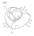
- the figure 3 illustrates the first module 102 where it can be seen that each of the optical systems is formed of a lens extending substantially uniformly over its entire length.
- the ends of the lenses may be contiguous with those of neighboring lenses.
- the reflective surfaces 112, 112 'and 112 "of the three lenses can be observed, respectively, the light sources and the support are not visible at the figure 3 .
- the Figures 4, 5 and 6 are isolux curves (that is to say, same illuminance) beams produced by these three optical systems.
- the three beams produced are broad in the manner of a basic beam of a daytime signaling function, crossing lighting or road lighting.
- the beams of Figures 4 and 5 have a cut at the horizon whereas the beam of the figure 6 overflows beyond the horizon, especially as in a road lighting function.
- the beam of the figure 4 can correspond to the base of a crossover lighting function while the figure 5 can be the basis of a daytime signaling function.
- Horizontal beam spreading of optical systems from the first module 102 to the figure 3 is essentially related to the extent of their lenses according to their main directions. Calculation methods that are well known to those skilled in the art make it possible to define the lenses, more particularly their exit faces and their reflection faces, in order to produce the beams illustrated in FIGS. Figures 4 to 6 .
- the figure 7 illustrates the basic principles of the construction of diurnal, crossing and road signal beams.
- the continuous line footprint below the horizon illustrates the beam portion common to the crossing and road lighting functions. This is a beam with wide spread and close to the vehicle.
- the simple dashed footprint is a part of the passing beam, this part having a cut and a portion above the horizon.
- the double dashed footprint (line + point) is the additional long-range beam above the horizon for the road lighting function.
- the second and third modules may have optical systems that are somewhat different from the optical systems of the first module and which have just been described.
- the second module 202 represented at figure 8 comprises an optical system 204 'whose lens is limited in the horizontal plane or perpendicular to its axis of rotation.
- the lens has an exit face 214 'projecting relative to the lateral portions of the lens, and in the direction of its optical axis.
- the rays reflected by the reflecting surface 212 'of the lens in question and meeting the diopter formed by the protruding outlet face 212' with a deflection angle with respect to the optical axis will then be refracted so as to be straightened and form a beam less spread out and therefore more concentrated.
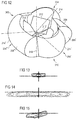
- the figure 10 illustrates the beam produced by the optical system 204 'of the second module 202. It can indeed be observed that it is substantially more limited in the horizontal direction and that it is mainly above the horizon. he can to complement a daytime function or road lighting function.
- the other two optical systems 204 and 204 "of the second module 202 are similar to those of the first module 102.
- Figures 9 and 11 illustrate the beams produced by these optical systems.
- the beam of the figure 9 can correspond to a daytime signal beam and the beam of the figure 11 can correspond to a lower part of a road lighting beam.
- the third module 302 illustrated at figure 12 it comprises two optical systems 304 and 304 'similar to the optical system 204' of the second module 202.
- These optical systems in fact comprise a limited lens whose output face 314 and 314 'has a rounded shape and protrudes from the lateral portions of the lens (in the horizontal plane). Similar to what was previously described in relation to the Figures 8 and 10 , the rounded shape of the output faces can produce beams substantially more concentrated in the horizontal direction.
- the beam of the figure 13 is similar to that of the figure 10 . It may correspond to a complement of daytime signaling beam or road lighting.
- the beam of the figure 15 is particular, besides the fact that it is little spread, in that it has, on the one hand, a cut and, on the other hand, a lateral portion above the horizon.
- a beam may for example correspond to a complement to the passing beam in a so-called motorway variant (or "Highway" in English).
- the right lateral portion extending above the horizon may in particular be obtained by inclining the light source (not visible) correspondingly.
- the optical system 304 is similar to the three optical systems of the first module 102 and the optical systems 204 and 204" of the second module 202. It produces a spread beam, as illustrated in FIG. figure 14 , and it is similar to those of Figures 4 to 6 , 9 and 11 . It may correspond to a cross-beam lighting beam part.
- the lighting and / or signaling system thus described makes it possible to produce, with a single system, several beams corresponding to radically different functions, such as, for example, daytime signaling, crossing and road. It also makes it possible to produce variations of these basic functions by adding or removing certain beam additions. Indeed, for example, the crossing lighting function can be completed with a less spread beam and beyond one side of the horizon to achieve a so-called highway lighting function.
- the light source can be colored or covered with a colored filter.
Landscapes
- Engineering & Computer Science (AREA)
- General Engineering & Computer Science (AREA)
- Physics & Mathematics (AREA)
- Microelectronics & Electronic Packaging (AREA)
- Optics & Photonics (AREA)
- Lighting Device Outwards From Vehicle And Optical Signal (AREA)
- Non-Portable Lighting Devices Or Systems Thereof (AREA)
Applications Claiming Priority (1)
| Application Number | Priority Date | Filing Date | Title |
|---|---|---|---|
| FR1359426A FR3011313B1 (fr) | 2013-09-30 | 2013-09-30 | Systeme d'eclairage et/ou de signalisation lumineuse pour vehicule automobile avec plusieurs modules multifonction rotatifs |
Publications (1)
| Publication Number | Publication Date |
|---|---|
| EP2853805A1 true EP2853805A1 (de) | 2015-04-01 |
Family
ID=49713265
Family Applications (1)
| Application Number | Title | Priority Date | Filing Date |
|---|---|---|---|
| EP14187198.8A Withdrawn EP2853805A1 (de) | 2013-09-30 | 2014-09-30 | Beleuchtungs- und/oder Lichtsignalisierungssystem für Kraftfahrzeug mit mehreren drehbaren Multifunktionsmodulen |
Country Status (2)
| Country | Link |
|---|---|
| EP (1) | EP2853805A1 (de) |
| FR (1) | FR3011313B1 (de) |
Cited By (2)
| Publication number | Priority date | Publication date | Assignee | Title |
|---|---|---|---|---|
| WO2022183711A1 (zh) * | 2021-03-01 | 2022-09-09 | 华域视觉科技(上海)有限公司 | 车灯模组、车辆及车灯照明模组出射光形的形成方法 |
| CN118189094A (zh) * | 2024-04-01 | 2024-06-14 | 南宁燎旺车灯股份有限公司 | 一种光学装置、车灯和交通工具 |
Citations (6)
| Publication number | Priority date | Publication date | Assignee | Title |
|---|---|---|---|---|
| EP1077158A1 (de) * | 1999-08-19 | 2001-02-21 | Peugeot Citroen Automobiles SA | Fahrzeugbeleuchtungs- und/oder Signaleinrichtung und Fahrzeug mit einer solchen Einrichtung |
| DE202007018181U1 (de) * | 2007-12-31 | 2008-05-08 | Automotive Lighting Reutlingen Gmbh | Projektionsmodul mit dynamischer Kurvenlichtfunktion |
| WO2010093278A1 (ru) * | 2009-02-16 | 2010-08-19 | ДЯДЕЧКО, Иван Петрович | Фара с изменяемыми характеристиками освещения |
| EP2280215A2 (de) | 2009-07-31 | 2011-02-02 | Zizala Lichtsysteme GmbH | LED-Kraftfahrzeugscheinwerfer zur Erzeugung einer dynamischen Lichtverteilung |
| EP2434204A2 (de) * | 2010-09-27 | 2012-03-28 | Audi AG | Scheinwerfer für ein Kraftfahrzeug und Kraftfahrzeug |
| EP2799286A1 (de) * | 2013-05-02 | 2014-11-05 | Valeo Vision | Drehbar und multifunktionnale Modul für Signalisierung und/or für Beleuchtung |
-
2013
- 2013-09-30 FR FR1359426A patent/FR3011313B1/fr not_active Expired - Fee Related
-
2014
- 2014-09-30 EP EP14187198.8A patent/EP2853805A1/de not_active Withdrawn
Patent Citations (6)
| Publication number | Priority date | Publication date | Assignee | Title |
|---|---|---|---|---|
| EP1077158A1 (de) * | 1999-08-19 | 2001-02-21 | Peugeot Citroen Automobiles SA | Fahrzeugbeleuchtungs- und/oder Signaleinrichtung und Fahrzeug mit einer solchen Einrichtung |
| DE202007018181U1 (de) * | 2007-12-31 | 2008-05-08 | Automotive Lighting Reutlingen Gmbh | Projektionsmodul mit dynamischer Kurvenlichtfunktion |
| WO2010093278A1 (ru) * | 2009-02-16 | 2010-08-19 | ДЯДЕЧКО, Иван Петрович | Фара с изменяемыми характеристиками освещения |
| EP2280215A2 (de) | 2009-07-31 | 2011-02-02 | Zizala Lichtsysteme GmbH | LED-Kraftfahrzeugscheinwerfer zur Erzeugung einer dynamischen Lichtverteilung |
| EP2434204A2 (de) * | 2010-09-27 | 2012-03-28 | Audi AG | Scheinwerfer für ein Kraftfahrzeug und Kraftfahrzeug |
| EP2799286A1 (de) * | 2013-05-02 | 2014-11-05 | Valeo Vision | Drehbar und multifunktionnale Modul für Signalisierung und/or für Beleuchtung |
Cited By (2)
| Publication number | Priority date | Publication date | Assignee | Title |
|---|---|---|---|---|
| WO2022183711A1 (zh) * | 2021-03-01 | 2022-09-09 | 华域视觉科技(上海)有限公司 | 车灯模组、车辆及车灯照明模组出射光形的形成方法 |
| CN118189094A (zh) * | 2024-04-01 | 2024-06-14 | 南宁燎旺车灯股份有限公司 | 一种光学装置、车灯和交通工具 |
Also Published As
| Publication number | Publication date |
|---|---|
| FR3011313A1 (fr) | 2015-04-03 |
| FR3011313B1 (fr) | 2018-02-02 |
Similar Documents
| Publication | Publication Date | Title |
|---|---|---|
| EP3181991B1 (de) | Kraftfahrzeug-beleuchtungsmodul mit kombinerter abblend- und fernlichtfunktion und einer regulierbaren lichtquelle | |
| EP3521691B1 (de) | Leuchtmodul für kraftfahrzeug, und beleuchtungs- und/oder signalisierungsvorrichtung, die mit einem solchen modul ausgestattet ist | |
| EP3301348B1 (de) | Bandförmige beleuchtungsvorrichtung für kraftfahrzeugscheinwerfer | |
| EP2743567B1 (de) | Optisches hauptelement, beleuchtungsmodul und scheinwerfer für kraftfahrzeug | |
| EP3115256B1 (de) | Kontrollverfahren eines lichtbündels, und entsprechendes beleuchtungssystem | |
| EP4264120A1 (de) | Kraftfahrzeugscheinwerfer mit mehreren beleuchtungsmodulen auf einer geneigten gemeinsamen platte | |
| EP3147557A1 (de) | Primäres optisches element für kraftfahrzeugsbeleuchtungsmodul | |
| EP4062098B1 (de) | Kombiniertes leuchtmodul zur abbildung der beleuchteten fläche eines kollektors | |
| EP3521692B1 (de) | Bifunktions-leuchtmodul mit gemeinsamer beleuchteter fläche | |
| EP2813395A1 (de) | Kraftfahrzeug-Scheinwerfer, der eine Laser-Lichtquelle umfasst und Verfahren zur Erzeugung eines Lichtbündel | |
| EP3803198B1 (de) | Lichtmodul für ein automobil-fahrzeug | |
| FR2995967B1 (fr) | Module d'eclairage, notamment pour vehicule automobile | |
| EP4051954B1 (de) | Zwischen links- und rechtslenker verstellbarer automobilscheinwerfer | |
| FR2977927A1 (fr) | Dispositif d'eclairage/signalisation multifonctions pour vehicule automobile. | |
| EP3470727B1 (de) | Beleuchtungsmodul, das ein lichtmuster bildet, dessen oberer teil scharfe vertikale kanten und dessen unterer teil unscharfe vertikale kanten aufweist | |
| EP4285051A1 (de) | Kraftfahrzeugvorrichtung zur beleuchtung der strasse | |
| EP3453946A1 (de) | Leuchtmodul für kraftfahrzeug, und beleuchtungs- und/oder signalisierungsvorrichtung, die mit einem solchen modul ausgestattet ist | |
| EP2853805A1 (de) | Beleuchtungs- und/oder Lichtsignalisierungssystem für Kraftfahrzeug mit mehreren drehbaren Multifunktionsmodulen | |
| EP4264123B1 (de) | Beleuchtungsvorrichtung mit doppelfunktion und rotierender linse | |
| WO1999011969A1 (fr) | Projecteur pour vehicule automobile, susceptible d'emettre des faisceaux differents | |
| EP3290774A1 (de) | Beleuchtungsmodul mit diffraktiver blende für kraftfahrzeug | |
| EP2853804B1 (de) | Beleuchtungs- und/oder signalisierungsmodul mit mehreren drehbaren optischen systemen | |
| FR3138789A1 (fr) | Projecteur á coupure et étendu verticalement pour véhicule automobile | |
| FR3056697A1 (fr) | Module d'eclairage automobile avec lentille a focale reglable | |
| EP3276249B1 (de) | Leuchtsystem für beleuchtungsvorrichtung und optional für signalvorrichtung für kraftfahrzeug |
Legal Events
| Date | Code | Title | Description |
|---|---|---|---|
| PUAI | Public reference made under article 153(3) epc to a published international application that has entered the european phase |
Free format text: ORIGINAL CODE: 0009012 |
|
| 17P | Request for examination filed |
Effective date: 20140930 |
|
| AK | Designated contracting states |
Kind code of ref document: A1 Designated state(s): AL AT BE BG CH CY CZ DE DK EE ES FI FR GB GR HR HU IE IS IT LI LT LU LV MC MK MT NL NO PL PT RO RS SE SI SK SM TR |
|
| AX | Request for extension of the european patent |
Extension state: BA ME |
|
| R17P | Request for examination filed (corrected) |
Effective date: 20150922 |
|
| RBV | Designated contracting states (corrected) |
Designated state(s): AL AT BE BG CH CY CZ DE DK EE ES FI FR GB GR HR HU IE IS IT LI LT LU LV MC MK MT NL NO PL PT RO RS SE SI SK SM TR |
|
| STAA | Information on the status of an ep patent application or granted ep patent |
Free format text: STATUS: EXAMINATION IS IN PROGRESS |
|
| 17Q | First examination report despatched |
Effective date: 20210617 |
|
| STAA | Information on the status of an ep patent application or granted ep patent |
Free format text: STATUS: THE APPLICATION HAS BEEN WITHDRAWN |
|
| 18W | Application withdrawn |
Effective date: 20211101 |