EP2862641A1 - Verfahren zur Herstellung metallischer Verbundrohre - Google Patents
Verfahren zur Herstellung metallischer Verbundrohre Download PDFInfo
- Publication number
- EP2862641A1 EP2862641A1 EP13306420.4A EP13306420A EP2862641A1 EP 2862641 A1 EP2862641 A1 EP 2862641A1 EP 13306420 A EP13306420 A EP 13306420A EP 2862641 A1 EP2862641 A1 EP 2862641A1
- Authority
- EP
- European Patent Office
- Prior art keywords
- metal
- tube
- layer
- strip
- slot
- Prior art date
- Legal status (The legal status is an assumption and is not a legal conclusion. Google has not performed a legal analysis and makes no representation as to the accuracy of the status listed.)
- Granted
Links
Images

Classifications
-
- B—PERFORMING OPERATIONS; TRANSPORTING
- B23—MACHINE TOOLS; METAL-WORKING NOT OTHERWISE PROVIDED FOR
- B23K—SOLDERING OR UNSOLDERING; WELDING; CLADDING OR PLATING BY SOLDERING OR WELDING; CUTTING BY APPLYING HEAT LOCALLY, e.g. FLAME CUTTING; WORKING BY LASER BEAM
- B23K31/00—Processes relevant to this subclass, specially adapted for particular articles or purposes, but not covered by any single one of main groups B23K1/00 - B23K28/00
- B23K31/02—Processes relevant to this subclass, specially adapted for particular articles or purposes, but not covered by any single one of main groups B23K1/00 - B23K28/00 relating to soldering or welding
- B23K31/027—Making tubes by soldering or welding
-
- B—PERFORMING OPERATIONS; TRANSPORTING
- B21—MECHANICAL METAL-WORKING WITHOUT ESSENTIALLY REMOVING MATERIAL; PUNCHING METAL
- B21C—MANUFACTURE OF METAL SHEETS, WIRE, RODS, TUBES, PROFILES OR LIKE SEMI-MANUFACTURED PRODUCTS OTHERWISE THAN BY ROLLING; AUXILIARY OPERATIONS USED IN CONNECTION WITH METAL-WORKING WITHOUT ESSENTIALLY REMOVING MATERIAL
- B21C37/00—Manufacture of metal sheets, rods, wire, tubes, profiles or like semi-manufactured products, not otherwise provided for; Manufacture of tubes of special shape
- B21C37/06—Manufacture of metal sheets, rods, wire, tubes, profiles or like semi-manufactured products, not otherwise provided for; Manufacture of tubes of special shape of tubes or metal hoses; Combined procedures for making tubes, e.g. for making multi-wall tubes
- B21C37/08—Making tubes with welded or soldered seams
- B21C37/0826—Preparing the edges of the metal sheet with the aim of having some effect on the weld
-
- B—PERFORMING OPERATIONS; TRANSPORTING
- B21—MECHANICAL METAL-WORKING WITHOUT ESSENTIALLY REMOVING MATERIAL; PUNCHING METAL
- B21C—MANUFACTURE OF METAL SHEETS, WIRE, RODS, TUBES, PROFILES OR LIKE SEMI-MANUFACTURED PRODUCTS OTHERWISE THAN BY ROLLING; AUXILIARY OPERATIONS USED IN CONNECTION WITH METAL-WORKING WITHOUT ESSENTIALLY REMOVING MATERIAL
- B21C37/00—Manufacture of metal sheets, rods, wire, tubes, profiles or like semi-manufactured products, not otherwise provided for; Manufacture of tubes of special shape
- B21C37/06—Manufacture of metal sheets, rods, wire, tubes, profiles or like semi-manufactured products, not otherwise provided for; Manufacture of tubes of special shape of tubes or metal hoses; Combined procedures for making tubes, e.g. for making multi-wall tubes
- B21C37/08—Making tubes with welded or soldered seams
- B21C37/09—Making tubes with welded or soldered seams of coated strip material ; Making multi-wall tubes
-
- B—PERFORMING OPERATIONS; TRANSPORTING
- B23—MACHINE TOOLS; METAL-WORKING NOT OTHERWISE PROVIDED FOR
- B23K—SOLDERING OR UNSOLDERING; WELDING; CLADDING OR PLATING BY SOLDERING OR WELDING; CUTTING BY APPLYING HEAT LOCALLY, e.g. FLAME CUTTING; WORKING BY LASER BEAM
- B23K37/00—Auxiliary devices or processes, not specially adapted for a procedure covered by only one of the other main groups of this subclass
Definitions
- the invention relates to a method for producing a tube from a strip which consists of a layer of a first metal and a layer of a second metal, wherein the layers are metallurgically firmly bonded to one another over the entire length of the strip, with which the strip is running in length is formed into a slit pipe such that its longitudinal edges abut each other at a longitudinally extending slot, and with which the slit is welded to form a completely closed pipe.
- Metallic tubes made of two layers of different metals have many applications, especially in the cable industry and for the transport of gases and liquids.
- the desired properties of the metals used are advantageously exploited equally.
- a pipe may be plated on the outside for reasons of corrosion protection or for better heat conduction.
- Electrically conductive cables can be made of the inexpensive base material aluminum with a plated, well electrically conductive copper layer.
- Such CCA pipes copper - clad aluminum for copper-clad aluminum
- a metallic layer can be applied galvanically to a metal tube, as is done, for example, in the manufacture of galvanized steel tubes.
- the result is an insoluble composite of the two metal layers. Electroplating is an energy-intensive process and involves relatively low production speeds.
- the mechanical processes include, for example, plating.
- a metallic ribbon is a thin ribbon from another Rolled metal.
- Such a plated metal strip can then be formed into a tube and welded.
- a disadvantage of this method is that there is no closed, uniform outer layer in the weld area of the tube, since the two metals mix during welding. This has the consequence that the material properties of the pipe in the weld area can not be controlled controlled and they can be significantly different from those of the rest of the tube. In addition, it can come to the embrittlement of the weld by mixing.
- the EP 1 469486 B1 describes a copper-coated aluminum strip which can be used for example for producing coaxial cables.
- the copper clad strip is fabricated for a desired application so that the aluminum strip is slightly wider than the copper strip.
- the band formed into a tube only the aluminum is welded.
- the copper layer along the aluminum weld has a gap.
- the power line characteristics of the finished cable are therefore particularly affected in the high frequency range.
- the aluminum is exposed to corrosion in the weld area.
- the invention has for its object to provide a continuous process for the production of high quality pipes, which have a uniform, completely closed outer layer and no material property changes in the weld area with respect to the remaining tube.
- the invention also provides the advantages that the inventive method is flexible, allows high production speeds, is associated with relatively low production costs and requires relatively little energy.
- the step of removing the strips of the first metal has the advantage that plated metal strips having a larger initial width than necessary for the tube to be produced can be used in the method according to the invention.
- metal strips are cut to the required width needed for the desired application. The cut strips can then be trimmed at their edges, for example by means of a roller shear, so that it is possible to use a cut strip for the production of tubes with slightly different tube diameters.
- the inventive method for producing plated metal pipes is thus flexible and inexpensive.
- a tube made of metal is produced by the process according to the invention.
- a metal strip 10 is withdrawn.
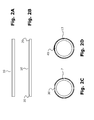
- the band 10, shown in FIG Fig. 2A consists of a layer of a first metal and a layer of a second metal, wherein the layers are metallurgically firmly bonded together over the entire length of the strip.
- the first metal is removed from the second metal in strips extending over the entire length of the strip at both longitudinal edges of the strip 10.
- Fig. 2B schematically shows the metal strip 10 with the points 20 at which the strips of the first metal have been removed. Partial removal of the second metal during this operation has no significant influence on the quality of the finished tube.
- the belt 10 is then fed to a former 4, e.g. a roller or sliding tool fed.
- a former 4 e.g. a roller or sliding tool fed.
- Between the tape supply 1 and the forming device 4 may be a Bandkanten- or roller scissors 5, by means of which the tape 10 is cut to size.
- the scissors 5 may be arranged in front of or behind the paring knife 3.
- the strip 10 is subsequently formed in the forming device 4 into a slot tube, in such a way that the layer of the first metal is on the outside.
- a cable core or other type of filling (not shown) can be supplied, around which the slot tube is guided.
- the abutting edges of the layer of the second metal extending in the longitudinal direction of the slot tube are welded together in a welding device 6 in order to obtain a completely closed tube 7.
- a cross section of the welded tube 7 with a gap 30 of the first metal in the region of the weld is in Fig. 2C illustrated.
- the longitudinal seam welding is preferably tungsten inert gas or laser welding.
- a layer of the first metal is then applied to the second metal in a second welding device 8 applied to obtain a tube with a completely closed layer of the first metal.
- a cross-section of the finished tube 13, in which the coated layer 40 of the first metal completely closes the gap left after the welding of the slot tube, is in FIG Fig. 2D shown.
- the first metal in the form of powder, wire or strip is continuously fed to the weld and the material is welded by means of a laser beam.
- the surface application is preferably carried out under a protective atmosphere.
- the finished pipe 13 can be detected by a take-off device 11 and pulled through a arranged in front of the extraction device 11 12 to reduce the diameter. If the tube contains a soul, the tube is pulled down the diameter of the same reduced so that it comes to rest on the soul, so that an existing air gap between the tube and the soul is removed.
- the diameter-reducing device 12 may be, for example, a die.
- the diameter-reducing device 12 may consist of at least one roller frame (eg a so-called Turk's head). The roller frame can be driven or not driven. In this drawing or rolling process, the surface of the outer first metal in the application area is simultaneously smoothed or evened out. The wall thickness of the tube is not reduced in this reduction step.
- the extraction device 11 may for example consist of a tape or a collet chuck. As in Fig. 1 shown, another extraction device 14 may be arranged in front of the die or roller frame 12.
- the further take-off device 14 applies the force required to unwind the metal strip 10 from the unwinder 1 and to pull it through the strip edge scissors 5 and the forming device 4, if present, provided that they do not have their own drive.
- the extraction device 11 must then apply only the force required for the deformation of the tube 13 in the die or roller frame 12. Furthermore, when pulling down the tube, torsion and smaller vibrations thereof may occur occur. These movements can have a negative effect on the welding result.
- the further take-off device 14 is used for decoupling the effects of reducing the welding in the upstream welding devices 6, 8.
- the finished metal tube 13 can subsequently be supplied to further processing or storage devices (not shown), for example a rewinder or a cutting unit.
- CCA tube which consists of an aluminum tube having an outer copper layer.
- Such CCA tubes can serve, for example, as an inner conductor and shielding in high-frequency cables or as shielding in high-voltage cables.
- steel or stainless steel tubes which have a copper or a zinc layer on the outside, which serves to protect against corrosion.
- steel pipes outside can have a decorative brass layer.
- the method according to the invention is suitable for the production of metal tubes with a circular cross section as well as for tubes with other cross sections, for example rectangular tubes.
- Composite pipes of all types or cable sheathing can be produced by the method according to the invention.
- metals mentioned non-ferrous metals and alloys of various metals can also be used.
Landscapes
- Engineering & Computer Science (AREA)
- Mechanical Engineering (AREA)
- Physics & Mathematics (AREA)
- Optics & Photonics (AREA)
- Butt Welding And Welding Of Specific Article (AREA)
- Arc Welding In General (AREA)
- Laser Beam Processing (AREA)
Abstract
Description
- Die Erfindung bezieht sich auf ein Verfahren zur Herstellung eines Rohres aus einem Band, welches aus einer Schicht eines ersten Metalls und einer Schicht eines zweiten Metalls besteht, wobei die Schichten auf der gesamten Länge des Bandes metallurgisch fest miteinander verbunden sind, mit welchem das Band längseinlaufend so zu einem Schlitzrohr geformt wird, daß seine Längskanten an einem sich in Längsrichtung erstreckenden Schlitz aneinander liegen, und mit welchem der Schlitz zur Bildung eines rundum geschlossenen Rohres verschweißt wird.
- Metallische Rohre aus zwei Schichten unterschiedlicher Metalle haben vielfältige Anwendungen, insbesondere in der Kabelindustrie und für den Transport von Gasen und Flüssigkeiten. Bei derartigen Verbundrohren werden die gewünschten Eigenschaften der verwendeten Metalle vorteilhaft gleichermaßen ausgenutzt. Beispielsweise kann ein Rohr aus Gründen des Korrosionsschutzes oder zur besseren Wärmeleitung außen plattiert sein. Elektrisch leitende Kabel können aus dem preiswerten Grundmaterial Aluminium mit einer darauf plattierten, gut elektrisch leitenden Kupferschicht bestehen. Derartige CCA-Rohre -(copper-clad aluminium für kupferkaschiertes Aluminium) eignen sich dank des Skin-Effektes besonders als Hochfrequenz-Stromleiter.
- Bekannte Verfahren zur Herstellung derartiger metallischer Rohre beruhen auf galvanischen oder mechanischen Verbundtechniken.
- Eine metallische Schicht kann galvanisch auf ein Metallrohr aufgetragen werden, wie es beispielsweise bei der Herstellung verzinkter Stahlrohre getan wird. Es entsteht ein unlösbarer Verbund der beiden Metallschichten. Das Galvanisieren ist ein energieintensiver Prozeß und mit relativ geringen Fertigungsgeschwindigkeiten verbunden.
- Zu den mechanischen Verfahren gehört beispielsweise das Plattieren. Auf ein metallisches Flachband wird ein dünnes Flachband aus einem anderen Metall aufgewalzt. Ein so plattierter Metallstreifen kann anschließend zu einem Rohr geformt und verschweißt werden. Ein Nachteil bei diesem Verfahren besteht darin, daß im Schweißnahtbereich des Rohrs keine geschlossene, gleichmäßige äußere Schicht vorliegt, da sich die beiden Metalle während des Verschweißens vermischen. Dies hat zur Folge, daß die Materialeigenschaften des Rohrs im Schweißnahtbereich nicht kontrolliert eingestellt werden können und sich diese erheblich von denen des übrigen Rohrs unterscheiden können. Außerdem kann es durch die Vermischung zur Versprödung der Schweißnaht kommen.
- Die
EP 1 469486 B1 beschreibt einen mit Kupfer beschichteten Aluminiumstreifen, welcher beispielsweise zur Herstellung koaxialer Kabel verwendet werden kann. Das kupferplattierte Band wird für eine gewünschte Anwendung so hergestellt, daß der Aluminiumstreifen etwas breiter als der Kupferstreifen ist. Beim Verschweißen des zu einem Rohr geformten Bandes wird nur das Aluminium verschweißt. Dies hat allerdings zur Folge, daß die Kupferschicht entlang der Aluminiumschweißnaht eine Lücke aufweist. Die Stromleitungseigenschaften des fertigen Kabels sind deshalb besonders im Hochfrequenzbereich beeinträchtigt. Weiterhin ist das Aluminium im Schweißnahtbereich der Korrosion ausgesetzt. - Der Erfindung liegt die Aufgabe zugrunde, ein kontinuierliches Verfahren zur Herstellung qualitativ hochwertiger Rohre bereitzustellen, welche eine gleichmäßige, rundum geschlossene äußere Schicht und keine Materialeigenschaftsänderungen im Schweißnahtbereich gegenüber dem verbleibenden Rohr aufweisen.
- Diese Aufgabe wird gemäß der Erfindung dadurch gelöst,
- daß an den beiden Längskanten des Bandes das erste Metall in über die gesamte Länge des Bandes verlaufenden Streifen vom zweiten Metall entfernt wird,
- daß das Band mit außen liegendem ersten Metall zum Schlitzrohr geformt wird,
- daß die aneinander liegenden Kanten der Schicht des zweiten Metalls miteinander verschweißt werden, und
- daß im Bereich der Schweißnaht eine Schicht des ersten Metalls auf das zweite Metall zur Fertigstellung eines Rohres mit einer rundum geschlossenen Schicht des ersten Metalls aufgetragen wird.
- Neben den sich aus der Aufgabenstellung direkt ergebenden Vorteilen stellt die Erfindung außerdem die Vorteile bereit, daß das erfindungsgemäße Verfahren flexibel ist, große Fertigungsgeschwindigkeiten erlaubt, mit relativ geringen Fertigungskosten verbunden ist und vergleichsweise wenig Energie benötigt. Insbesondere der Schritt des Entfernens der Streifen des ersten Metalls hat den Vorteil, daß plattierte Metallbänder mit größerer Ausgangsbreite als für das herzustellende Rohr nötig in dem erfindungsgemäßen Verfahren zum Einsatz kommen können. Von diesen breiten Metallbändern (in der Regel als Coilware vorliegend) werden Metallbänder mit der erforderlichen Breite geschnitten, die für die gewünschte Anwendung benötigt wird. Die zugeschnittenen Bänder können dann, beispielsweise mittels einer Rollenschere, an ihren Kanten beschnitten werden, so daß es möglich ist, ein zugeschnittenes Band zur Fertigung von Rohren mit geringfügig unterschiedlichen Rohrdurchmessern zu verwenden. Das erfindungsgemäße Verfahren zur Herstellung plattierter Metallrohre ist damit flexibel und kostengünstig.
- Das Verfahren gemäß der Erfindung wird anhand der Zeichnungen erläutert.
- Ausführungsbeispiele des Erfindungsgegenstandes sind in den Zeichnungen dargestellt. Es zeigen:
-
Fig. 1 in schematischer Darstellung eine Vorrichtung zur Herstellung eines Rohres aus Metall nach einem Ausführungsbeispiel des erfindungsgemäßen Verfahrens; -
Fig. 2A-2D in schematischer Darstellung jeweils einen Querschnitt des Metallbandes bzw. des Rohrs während erfindungsgemäßer Verfahrensschritte. - Mittels der in
Fig. 1 schematisch dargestellten Vorrichtung wird ein Rohr aus Metall nach dem erfindungsgemäßen Verfahren hergestellt. Von einem Bandvorrat 1 wird ein Metallband 10 abgezogen. Das Band 10, dargestellt inFig. 2A , besteht aus einer Schicht eines ersten Metalls und einer Schicht eines zweiten Metalls, wobei die Schichten auf der gesamten Länge des Bandes metallurgisch fest miteinander verbunden sind. In einer Schäl- oder Fräseinrichtung 3 wird an beiden Längskanten des Bandes 10 das erste Metall in über die gesamte Länge des Bandes verlaufenden Streifen vom zweiten Metall entfernt.Fig. 2B zeigt schematisch das Metallband 10 mit den Stellen 20, an denen die Streifen des ersten Metalls entfernt worden sind. Ein bei diesem Arbeitsschritt teilweises Mitentfernen des zweiten Metalls hat keinen wesentlichen Einfluß auf die Qualität des fertigen Rohres. - Das Band 10 wird anschließend einer Formvorrichtung 4, z.B. einem Rollen- oder Gleitwerkzeug, zugeführt. Zwischen dem Bandvorrat 1 und der Formvorrichtung 4 kann sich eine Bandkanten- oder Rollenschere 5 befinden, mittels derer das Band 10 auf Maß geschnitten wird. Die Schere 5 kann vor oder hinter dem Schälmesser 3 angeordnet sein.
- Zur Erzeugung des Rohrs wird das Band 10 anschließend in der Formvorrichtung 4 zu einem Schlitzrohr geformt, und zwar so, daß die Schicht des ersten Metalls außen liegt. Gleichzeitig kann eine Kabelseele oder eine andersgeartete Füllung (nicht dargestellt) zugeführt werden, um welche das Schlitzrohr herumgeführt wird. Die in der Längsrichtung des Schlitzrohrs verlaufenden, aneinander liegenden Kanten der Schicht des zweiten Metalls werden in einer Schweißeinrichtung 6 miteinander verschweißt, um ein rundum geschlossenes Rohr 7 zu erhalten. Ein Querschnitt des verschweißten Rohres 7 mit einer Lücke 30 des ersten Metalls im Bereich der Schweißnaht ist in
Fig. 2C veranschaulicht. Das Längsnahtschweißen ist vorzugsweise Wolfram-Inertgas- oder Laserschweißen. - Im Bereich der Schweißnaht wird dann in einer zweiten Schweißeinrichtung 8 eine Schicht des ersten Metalls auf das zweite Metall aufgetragen, um ein Rohr mit einer rundum geschlossenen Schicht des ersten Metalls zu erhalten. Ein Querschnitt des fertiggestellten Rohres 13, bei welchem die aufgetragene Schicht 40 des ersten Metalls die nach dem Verschweißen des Schlitzrohres verbliebene Lücke vollständig schließt, ist in
Fig. 2D gezeigt. Bei dem Auftragsschweißen wird das erste Metall in Form von Pulver, Draht oder Band der Schweißstelle kontinuierlich zugeführt und das Material mittels eines Laserstrahls verschweißt. Der Oberflächenauftrag erfolgt vorzugsweise unter Schutzatmosphäre. - Wie in
Fig. 1 dargestellt, kann das fertiggestellte Rohr 13 von einer Abzugsvorrichtung 11 erfaßt und durch eine vor der Abzugsvorrichtung 11 angeordneten Einrichtung 12 zur Reduzierung des Durchmessers gezogen werden. Falls das Rohr eine Seele enthält, wird beim Herunterziehen des Rohrs der Durchmesser desselben derart reduziert, daß es zur Anlage auf der Seele kommt, so daß ein eingangs vorhandener Luftspalt zwischen Rohr und Seele entfernt wird. Die durchmesserreduzierende Einrichtung 12 kann beispielsweise ein Ziehstein sein. Ebenso kann die durchmesserreduzierende Einrichtung 12 aus mindestens einem Rollengestell bestehen (z.B. einem sogenannten Türkenkopf). Das Rollengestell kann angetrieben oder nicht angetrieben sein. Bei diesem Zieh- bzw. Walzprozeß wird gleichzeitig die Oberfläche des außen liegenden ersten Metalls im Auftragsbereich geglättet bzw. vergleichmäßigt. Die Wandstärke des Rohrs wird bei diesem Reduktionsschritt nicht verringert. - Die Abzugsvorrichtung 11 kann beispielsweise aus einem Bandabzug oder einem Spannzangenabzug bestehen. Wie in
Fig. 1 dargestellt, kann eine weitere Abzugsvorrichtung 14 vor dem Ziehstein bzw. Rollengestell 12 angeordnet sein. Die weitere Abzugsvorrichtung 14 bringt die Kraft auf, die erforderlich ist, um das Metallband 10 vom Abwickler 1 abzuwickeln und durch die eventuell vorhandene Bandkantenschere 5 und die Formvorrichtung 4 zu ziehen, sofern dieselben keinen eigenen Antrieb haben. Die Abzugsvorrichtung 11 muß dann nur die Kraft aufbringen, die zur Verformung des Rohrs 13 im Ziehstein bzw. Rollengestell 12 erforderlich ist. Weiterhin können beim Herunterziehen des Rohres eine Torsion und kleinere Vibrationen desselben auftreten. Diese Bewegungen können sich negativ auf das Schweißergebnis auswirken. Die weitere Abzugsvorrichtung 14 dient zur Entkopplung der Einflüsse des Reduzierens auf das Schweißen in den vorgelagerten Schweißeinrichtungen 6, 8. - Das fertige Metallrohr 13 kann anschließend weiteren Verarbeitungs- oder Lagereinrichtungen (nicht dargestellt), beispielsweise einem Aufwickler oder einer Schneideeinheit, zugeführt werden.
- Ein Beispiel eines Rohrs, welches mit dem beschriebenen Verfahren hergestellt wird, ist das bereits erwähnte CCA-Rohr, welches aus einem Aluminiumrohr besteht, das eine äußere Kupferschicht aufweist. Solche CCA-Rohre können beispielsweise als Innenleiter und Abschirmung in Hochfrequenzkabeln oder als Abschirmung in Hochspannungskabeln dienen.
- Ein weiteres Beispiel sind Stahl- oder Edelstahlrohre, die außen eine Kupfer- oder eine Zinkschicht aufweisen, die dem Korrosionsschutz dient. Ebenfalls können Stahlrohre außen eine dekorative Messingschicht besitzen.
- Das erfindungsgemäße Verfahren eignet sich für die Herstellung von Metallrohren mit kreisförmigem Querschnitt als auch für Rohre mit anderen Querschnitten, beispielsweise Rechteckrohre. Verbundrohre aller Art bzw. Kabelummantelungen können mit dem erfindungsgemäßen Verfahren hergestellt werden. Anstelle der genannten Metalle können auch Nichteisenmetalle sowie Legierungen verschiedener Metalle zum Einsatz kommen.
Claims (10)
- Verfahren zur Herstellung eines Rohres aus einem Band, welches aus einer Schicht eines ersten Metalls und einer Schicht eines zweiten Metalls besteht, wobei die Schichten auf der gesamten Länge des Bandes metallurgisch fest miteinander verbunden sind, mit welchem das Band längseinlaufend so zu einem Schlitzrohr geformt wird, daß seine Längskanten an einem sich in Längsrichtung erstreckenden Schlitz aneinander liegen, und mit welchem der Schlitz zur Bildung eines rundum geschlossenen Rohres verschweißt wird, dadurch gekennzeichnet,- daß an den beiden Längskanten des Bandes das erste Metall in über die gesamte Länge des Bandes verlaufenden Streifen vom zweiten Metall entfernt wird,- daß das Band mit außen liegendem ersten Metall zum Schlitzrohr geformt wird,- daß die aneinander liegenden Kanten der Schicht des zweiten Metalls miteinander verschweißt werden, und- daß im Bereich der Schweißnaht eine Schicht des ersten Metalls auf das zweite Metall zur Fertigstellung eines Rohres mit einer rundum geschlossenen Schicht des ersten Metalls aufgetragen wird.
- Verfahren nach Anspruch 1 , dadurch gekennzeichnet, daß die Schicht des ersten Metalls im Bereich der Schweißnaht mittels Laserauftragsschweißen aufgetragen wird.
- Verfahren nach Anspruch 1 oder 2, dadurch gekennzeichnet, daß die Schicht des ersten Metalls im Bereich der Schweißnaht unter Schutzatmosphäre aufgetragen wird.
- Verfahren nach einem der vorangehenden Ansprüche, dadurch gekennzeichnet, daß das Rohr in mindestens einer Reduzierstufe in seinem Durchmesser reduziert wird.
- Verfahren nach einem der vorangehenden Ansprüche, dadurch gekennzeichnet, daß in das noch unverschweißte Schlitzrohr eine Seele eingeführt wird.
- Verfahren nach Anspruch 5, dadurch gekennzeichnet, daß das Rohr bis zur Anlage auf der Seele in mindestens einer Reduzierstufe in seinem Durchmesser reduziert wird.
- Verfahren nach einem der vorangehenden Ansprüche, dadurch gekennzeichnet, daß das erste Metall Kupfer und das zweite Metall Aluminium ist
- Verfahren nach einem der Ansprüche 1 bis 6, dadurch gekennzeichnet, daß das erste Metall Zink oder Kupfer und das zweite Metall Stahl ist.
- Verfahren nach einem der vorangehenden Ansprüche, dadurch gekennzeichnet, daß die Bandkanten des Metallbands vor der Rohrformung beschnitten werden.
- Verfahren nach einem der vorangehenden Ansprüche, dadurch gekennzeichnet, daß das Rohr einen runden, eckigen oder anders gearteten Querschnitt aufweist.
Priority Applications (5)
| Application Number | Priority Date | Filing Date | Title |
|---|---|---|---|
| EP13306420.4A EP2862641B1 (de) | 2013-10-16 | 2013-10-16 | Verfahren zur Herstellung metallischer Verbundrohre |
| US14/514,539 US9162322B2 (en) | 2013-10-16 | 2014-10-15 | Method of producing metallic composite pipes |
| KR1020140138975A KR102280964B1 (ko) | 2013-10-16 | 2014-10-15 | 금속성 복합 파이프 제조 방법 |
| CN201410858503.2A CN104821523A (zh) | 2013-10-16 | 2014-10-15 | 金属复合管的制造方法 |
| CN202010401075.6A CN111664299A (zh) | 2013-10-16 | 2014-10-15 | 金属复合管的制造方法 |
Applications Claiming Priority (1)
| Application Number | Priority Date | Filing Date | Title |
|---|---|---|---|
| EP13306420.4A EP2862641B1 (de) | 2013-10-16 | 2013-10-16 | Verfahren zur Herstellung metallischer Verbundrohre |
Publications (2)
| Publication Number | Publication Date |
|---|---|
| EP2862641A1 true EP2862641A1 (de) | 2015-04-22 |
| EP2862641B1 EP2862641B1 (de) | 2018-07-11 |
Family
ID=49510091
Family Applications (1)
| Application Number | Title | Priority Date | Filing Date |
|---|---|---|---|
| EP13306420.4A Active EP2862641B1 (de) | 2013-10-16 | 2013-10-16 | Verfahren zur Herstellung metallischer Verbundrohre |
Country Status (4)
| Country | Link |
|---|---|
| US (1) | US9162322B2 (de) |
| EP (1) | EP2862641B1 (de) |
| KR (1) | KR102280964B1 (de) |
| CN (2) | CN104821523A (de) |
Cited By (1)
| Publication number | Priority date | Publication date | Assignee | Title |
|---|---|---|---|---|
| DE102018212810A1 (de) * | 2018-08-01 | 2020-02-06 | Bayerische Motoren Werke Aktiengesellschaft | Verfahren zum Schweißen eines verzinkten Kraftfahrzeugbauteils |
Families Citing this family (5)
| Publication number | Priority date | Publication date | Assignee | Title |
|---|---|---|---|---|
| CA3045300A1 (en) * | 2016-11-30 | 2018-06-07 | Corning Optical Communications LLC | Two piece armored optical cables |
| CN107891251B (zh) * | 2017-10-30 | 2019-04-23 | 宝鸡市博信金属材料有限公司 | 一种制备高纯氢气用超薄壁钒管的制造工艺 |
| ES2989098T3 (es) * | 2019-09-30 | 2024-11-25 | Nexans | Procedimiento para producir cables coaxiales con un conductor exterior, radialmente cerrado, de pared delgada |
| CN113751876B (zh) * | 2021-09-24 | 2023-04-28 | 宁波江丰电子材料股份有限公司 | 一种铜靶材组件焊接后焊缝的处理方法及铜靶材组件 |
| CN114352812B (zh) * | 2022-03-16 | 2022-06-28 | 河北华洋钢管有限公司 | 一种高强度耐磨损抗压高频直缝焊钢管 |
Citations (3)
| Publication number | Priority date | Publication date | Assignee | Title |
|---|---|---|---|---|
| DE2432962A1 (de) * | 1974-07-09 | 1976-01-29 | Wickeder Eisen & Stahlwerk | Verfahren zum widerstands-verbindungsschweissen von mit ihren kantflaechen einander gegenueberstehenden metallblechraendern |
| WO1996027475A1 (en) * | 1995-03-08 | 1996-09-12 | The Idod Trust | Method of forming seamed metal tube |
| EP1469486B1 (de) | 2003-04-17 | 2006-06-14 | Dofasco Tubular Products Corporation | Mit Kupfer beschichtete Aluminiumstreifen und Verfahren zum Herstellen von mit Kupfer beschichteten Aluminiumstreifen |
Family Cites Families (17)
| Publication number | Priority date | Publication date | Assignee | Title |
|---|---|---|---|---|
| DE4221167C2 (de) * | 1992-06-27 | 1997-08-14 | Hille & Mueller | Verfahren zur Herstellung eines Mehrlagenrohres aus Metall |
| US5344062A (en) * | 1993-06-24 | 1994-09-06 | The Idod Trust | Method of forming seamed metal tube |
| CN2276215Y (zh) * | 1996-04-04 | 1998-03-11 | 孙家建 | 螺纹套导线连接管 |
| JP2000046253A (ja) * | 1998-07-24 | 2000-02-18 | Calsonic Corp | 内部分割チューブの製造方法と内部分割チューブ |
| KR20020094579A (ko) * | 2001-06-12 | 2002-12-18 | 김갑영 | 냉공조용 파이프의 성형 방법 |
| US6732434B2 (en) * | 2002-04-15 | 2004-05-11 | General Motors Corporation | Process for forming aluminum hydroforms |
| US7015873B1 (en) * | 2004-06-10 | 2006-03-21 | Lockheed Martin Corporation | Thermally dissipating high RF power radiating antenna system |
| ES2319228T3 (es) * | 2006-10-27 | 2009-05-05 | Nexans | Procedimiento para fabricar un conductor electrico superconductivo. |
| CN200972353Y (zh) * | 2006-11-06 | 2007-11-07 | 金龙精密铜管集团股份有限公司 | 一种热交换用复合管 |
| CN100561078C (zh) * | 2008-06-02 | 2009-11-18 | 苏州宏太铜材有限公司 | 铝包铜毛细管的生产工艺 |
| CN101737565B (zh) * | 2008-11-04 | 2011-12-28 | 肖玉佳 | 一种制造铜铝复合管的方法 |
| KR101190011B1 (ko) * | 2009-12-14 | 2012-10-12 | 삼원동관 주식회사 | 이중관 타입의 냉장고용 석션파이프 구조 |
| CN201902820U (zh) * | 2010-12-23 | 2011-07-20 | 江苏其元集团有限公司 | 钢铜复合焊管 |
| GB2490143B (en) * | 2011-04-20 | 2013-03-13 | Rolls Royce Plc | Method of manufacturing a component |
| CN102941397B (zh) * | 2012-10-09 | 2015-05-13 | 中冶南方(武汉)威仕工业炉有限公司 | 一种镍基合金的钨极氩弧焊焊接方法 |
| CN102889434B (zh) * | 2012-10-24 | 2015-01-21 | 浙江金洲管道工业有限公司 | 一种不锈钢复合焊接钢管及其制造方法 |
| CN102982903B (zh) * | 2012-11-26 | 2017-05-24 | 大连通发新材料开发有限公司 | 生产铜包铝管的方法及所用的生产线 |
-
2013
- 2013-10-16 EP EP13306420.4A patent/EP2862641B1/de active Active
-
2014
- 2014-10-15 CN CN201410858503.2A patent/CN104821523A/zh active Pending
- 2014-10-15 CN CN202010401075.6A patent/CN111664299A/zh active Pending
- 2014-10-15 KR KR1020140138975A patent/KR102280964B1/ko not_active Expired - Fee Related
- 2014-10-15 US US14/514,539 patent/US9162322B2/en not_active Expired - Fee Related
Patent Citations (3)
| Publication number | Priority date | Publication date | Assignee | Title |
|---|---|---|---|---|
| DE2432962A1 (de) * | 1974-07-09 | 1976-01-29 | Wickeder Eisen & Stahlwerk | Verfahren zum widerstands-verbindungsschweissen von mit ihren kantflaechen einander gegenueberstehenden metallblechraendern |
| WO1996027475A1 (en) * | 1995-03-08 | 1996-09-12 | The Idod Trust | Method of forming seamed metal tube |
| EP1469486B1 (de) | 2003-04-17 | 2006-06-14 | Dofasco Tubular Products Corporation | Mit Kupfer beschichtete Aluminiumstreifen und Verfahren zum Herstellen von mit Kupfer beschichteten Aluminiumstreifen |
Cited By (1)
| Publication number | Priority date | Publication date | Assignee | Title |
|---|---|---|---|---|
| DE102018212810A1 (de) * | 2018-08-01 | 2020-02-06 | Bayerische Motoren Werke Aktiengesellschaft | Verfahren zum Schweißen eines verzinkten Kraftfahrzeugbauteils |
Also Published As
| Publication number | Publication date |
|---|---|
| KR20150044400A (ko) | 2015-04-24 |
| US9162322B2 (en) | 2015-10-20 |
| US20150102088A1 (en) | 2015-04-16 |
| CN111664299A (zh) | 2020-09-15 |
| CN104821523A (zh) | 2015-08-05 |
| KR102280964B1 (ko) | 2021-07-26 |
| EP2862641B1 (de) | 2018-07-11 |
Similar Documents
| Publication | Publication Date | Title |
|---|---|---|
| EP2862641B1 (de) | Verfahren zur Herstellung metallischer Verbundrohre | |
| EP3541563B1 (de) | Verfahren und vorrichtung zur herstellung eines kontinuierlichen bandförmigen verbundmaterials | |
| EP3324487B1 (de) | Verbindung eines elektrischen leiters mit einem anschlussteil | |
| EP3227969B1 (de) | Verfahren zum herstellen eines elektrischen anschlussteils | |
| EP3312956B1 (de) | Verfahren und vorrichtung zum abisolieren eines kabels mit einer mehrschichtigen ummantelung | |
| EP2216122A1 (de) | Schutzgasrohr und Kontaktrohr einer Vorrichtung zum verbesserten Engspaltschweißen | |
| WO2009013150A1 (de) | Verfahren zur herstellung eines drahtes aus kupfer oder aus einer kupferlegierung mittels strangpressen | |
| DE102006031839A1 (de) | Elektrisches Kontaktelement | |
| DE69013818T2 (de) | Verfahren zur Herstellung eines mit Leitkupfer ummantelten Fahrdrahtes aus Stahl. | |
| EP2216121A1 (de) | Schutzgasrohr und Kontaktrohr einer Vorrichtung zum verbesserten Engspaltschweißen | |
| EP3797890B1 (de) | Verfahren zur herstellung dünnwandiger hohlprofile kleiner durchmesser aus ne-metallen | |
| CH664107A5 (de) | Elektrode fuer drahtschneide-funkenerosion. | |
| EP2644311A1 (de) | Verfahren zum Schweißen mittels eines Lasers | |
| EP1200253A1 (de) | Verfahren zur herstellung eines aluminium-verbundswerkstoffes | |
| EP2216120A1 (de) | Schutzgasrohr und Kontaktrohr einer Vorrichtung zum verbesserten Engspaltschweißen | |
| DE102021108193B3 (de) | Rippenrohr sowie Verfahren zu dessen Herstellung | |
| DE2839684C2 (de) | Verfahren zum Herstellen kupfergelöteter Mehrlagenrohre | |
| DE2357045C2 (de) | Vorrichtung zum Aufbringen von Schmiermitteln bei der Herstellung längsnahtgeschweißter Rohre | |
| EP2668311B1 (de) | Thermisch und elektrisch hochleitfähiges aluminiumband | |
| EP3799083B1 (de) | Verfahren zur herstellung von koaxialkabeln mit einem dünnwandigen, radial geschlossenen äusseren leiter | |
| DE4118004A1 (de) | Verfahren zur herstellung von mit einer schicht aus aluminium plattiertem strangfoermigem gut | |
| EP1604768B1 (de) | Verfahren zur kontinuierlichen Herstellung längsnahtgeschweisster Metallrohre | |
| DE102014111628A1 (de) | Verbundwerkstoff und Verfahren zur Herstellung eines Verbundwerkstoffs | |
| DE3208738A1 (de) | Verfahren und vorrichtung zur oberflaechenbehandlung von metallischem gut | |
| WO2016023982A1 (de) | Verbundwerkstoff und verfahren zur herstellung eines verbundwerkstoffs |
Legal Events
| Date | Code | Title | Description |
|---|---|---|---|
| PUAI | Public reference made under article 153(3) epc to a published international application that has entered the european phase |
Free format text: ORIGINAL CODE: 0009012 |
|
| 17P | Request for examination filed |
Effective date: 20140912 |
|
| AK | Designated contracting states |
Kind code of ref document: A1 Designated state(s): AL AT BE BG CH CY CZ DE DK EE ES FI FR GB GR HR HU IE IS IT LI LT LU LV MC MK MT NL NO PL PT RO RS SE SI SK SM TR |
|
| AX | Request for extension of the european patent |
Extension state: BA ME |
|
| RAP1 | Party data changed (applicant data changed or rights of an application transferred) |
Owner name: NEXANS |
|
| GRAP | Despatch of communication of intention to grant a patent |
Free format text: ORIGINAL CODE: EPIDOSNIGR1 |
|
| INTG | Intention to grant announced |
Effective date: 20180208 |
|
| GRAA | (expected) grant |
Free format text: ORIGINAL CODE: 0009210 |
|
| AK | Designated contracting states |
Kind code of ref document: B1 Designated state(s): AL AT BE BG CH CY CZ DE DK EE ES FI FR GB GR HR HU IE IS IT LI LT LU LV MC MK MT NL NO PL PT RO RS SE SI SK SM TR |
|
| REG | Reference to a national code |
Ref country code: GB Ref legal event code: FG4D Free format text: NOT ENGLISH |
|
| REG | Reference to a national code |
Ref country code: CH Ref legal event code: EP |
|
| REG | Reference to a national code |
Ref country code: AT Ref legal event code: REF Ref document number: 1016356 Country of ref document: AT Kind code of ref document: T Effective date: 20180715 |
|
| GRAS | Grant fee paid |
Free format text: ORIGINAL CODE: EPIDOSNIGR3 |
|
| REG | Reference to a national code |
Ref country code: IE Ref legal event code: FG4D Free format text: LANGUAGE OF EP DOCUMENT: GERMAN |
|
| REG | Reference to a national code |
Ref country code: DE Ref legal event code: R096 Ref document number: 502013010580 Country of ref document: DE |
|
| REG | Reference to a national code |
Ref country code: FR Ref legal event code: PLFP Year of fee payment: 6 |
|
| REG | Reference to a national code |
Ref country code: NL Ref legal event code: MP Effective date: 20180711 |
|
| REG | Reference to a national code |
Ref country code: LT Ref legal event code: MG4D |
|
| PG25 | Lapsed in a contracting state [announced via postgrant information from national office to epo] |
Ref country code: NL Free format text: LAPSE BECAUSE OF FAILURE TO SUBMIT A TRANSLATION OF THE DESCRIPTION OR TO PAY THE FEE WITHIN THE PRESCRIBED TIME-LIMIT Effective date: 20180711 |
|
| PG25 | Lapsed in a contracting state [announced via postgrant information from national office to epo] |
Ref country code: FI Free format text: LAPSE BECAUSE OF FAILURE TO SUBMIT A TRANSLATION OF THE DESCRIPTION OR TO PAY THE FEE WITHIN THE PRESCRIBED TIME-LIMIT Effective date: 20180711 Ref country code: GR Free format text: LAPSE BECAUSE OF FAILURE TO SUBMIT A TRANSLATION OF THE DESCRIPTION OR TO PAY THE FEE WITHIN THE PRESCRIBED TIME-LIMIT Effective date: 20181012 Ref country code: NO Free format text: LAPSE BECAUSE OF FAILURE TO SUBMIT A TRANSLATION OF THE DESCRIPTION OR TO PAY THE FEE WITHIN THE PRESCRIBED TIME-LIMIT Effective date: 20181011 Ref country code: IS Free format text: LAPSE BECAUSE OF FAILURE TO SUBMIT A TRANSLATION OF THE DESCRIPTION OR TO PAY THE FEE WITHIN THE PRESCRIBED TIME-LIMIT Effective date: 20181111 Ref country code: RS Free format text: LAPSE BECAUSE OF FAILURE TO SUBMIT A TRANSLATION OF THE DESCRIPTION OR TO PAY THE FEE WITHIN THE PRESCRIBED TIME-LIMIT Effective date: 20180711 Ref country code: PL Free format text: LAPSE BECAUSE OF FAILURE TO SUBMIT A TRANSLATION OF THE DESCRIPTION OR TO PAY THE FEE WITHIN THE PRESCRIBED TIME-LIMIT Effective date: 20180711 Ref country code: SE Free format text: LAPSE BECAUSE OF FAILURE TO SUBMIT A TRANSLATION OF THE DESCRIPTION OR TO PAY THE FEE WITHIN THE PRESCRIBED TIME-LIMIT Effective date: 20180711 Ref country code: BG Free format text: LAPSE BECAUSE OF FAILURE TO SUBMIT A TRANSLATION OF THE DESCRIPTION OR TO PAY THE FEE WITHIN THE PRESCRIBED TIME-LIMIT Effective date: 20181011 Ref country code: LT Free format text: LAPSE BECAUSE OF FAILURE TO SUBMIT A TRANSLATION OF THE DESCRIPTION OR TO PAY THE FEE WITHIN THE PRESCRIBED TIME-LIMIT Effective date: 20180711 |
|
| PG25 | Lapsed in a contracting state [announced via postgrant information from national office to epo] |
Ref country code: AL Free format text: LAPSE BECAUSE OF FAILURE TO SUBMIT A TRANSLATION OF THE DESCRIPTION OR TO PAY THE FEE WITHIN THE PRESCRIBED TIME-LIMIT Effective date: 20180711 Ref country code: HR Free format text: LAPSE BECAUSE OF FAILURE TO SUBMIT A TRANSLATION OF THE DESCRIPTION OR TO PAY THE FEE WITHIN THE PRESCRIBED TIME-LIMIT Effective date: 20180711 Ref country code: LV Free format text: LAPSE BECAUSE OF FAILURE TO SUBMIT A TRANSLATION OF THE DESCRIPTION OR TO PAY THE FEE WITHIN THE PRESCRIBED TIME-LIMIT Effective date: 20180711 Ref country code: ES Free format text: LAPSE BECAUSE OF FAILURE TO SUBMIT A TRANSLATION OF THE DESCRIPTION OR TO PAY THE FEE WITHIN THE PRESCRIBED TIME-LIMIT Effective date: 20180711 |
|
| REG | Reference to a national code |
Ref country code: DE Ref legal event code: R097 Ref document number: 502013010580 Country of ref document: DE |
|
| PG25 | Lapsed in a contracting state [announced via postgrant information from national office to epo] |
Ref country code: RO Free format text: LAPSE BECAUSE OF FAILURE TO SUBMIT A TRANSLATION OF THE DESCRIPTION OR TO PAY THE FEE WITHIN THE PRESCRIBED TIME-LIMIT Effective date: 20180711 Ref country code: CZ Free format text: LAPSE BECAUSE OF FAILURE TO SUBMIT A TRANSLATION OF THE DESCRIPTION OR TO PAY THE FEE WITHIN THE PRESCRIBED TIME-LIMIT Effective date: 20180711 Ref country code: EE Free format text: LAPSE BECAUSE OF FAILURE TO SUBMIT A TRANSLATION OF THE DESCRIPTION OR TO PAY THE FEE WITHIN THE PRESCRIBED TIME-LIMIT Effective date: 20180711 |
|
| PLBE | No opposition filed within time limit |
Free format text: ORIGINAL CODE: 0009261 |
|
| STAA | Information on the status of an ep patent application or granted ep patent |
Free format text: STATUS: NO OPPOSITION FILED WITHIN TIME LIMIT |
|
| PG25 | Lapsed in a contracting state [announced via postgrant information from national office to epo] |
Ref country code: SM Free format text: LAPSE BECAUSE OF FAILURE TO SUBMIT A TRANSLATION OF THE DESCRIPTION OR TO PAY THE FEE WITHIN THE PRESCRIBED TIME-LIMIT Effective date: 20180711 Ref country code: DK Free format text: LAPSE BECAUSE OF FAILURE TO SUBMIT A TRANSLATION OF THE DESCRIPTION OR TO PAY THE FEE WITHIN THE PRESCRIBED TIME-LIMIT Effective date: 20180711 Ref country code: SK Free format text: LAPSE BECAUSE OF FAILURE TO SUBMIT A TRANSLATION OF THE DESCRIPTION OR TO PAY THE FEE WITHIN THE PRESCRIBED TIME-LIMIT Effective date: 20180711 |
|
| REG | Reference to a national code |
Ref country code: CH Ref legal event code: PL |
|
| 26N | No opposition filed |
Effective date: 20190412 |
|
| GBPC | Gb: european patent ceased through non-payment of renewal fee |
Effective date: 20181016 |
|
| REG | Reference to a national code |
Ref country code: BE Ref legal event code: MM Effective date: 20181031 |
|
| PG25 | Lapsed in a contracting state [announced via postgrant information from national office to epo] |
Ref country code: MC Free format text: LAPSE BECAUSE OF FAILURE TO SUBMIT A TRANSLATION OF THE DESCRIPTION OR TO PAY THE FEE WITHIN THE PRESCRIBED TIME-LIMIT Effective date: 20180711 Ref country code: LU Free format text: LAPSE BECAUSE OF NON-PAYMENT OF DUE FEES Effective date: 20181016 |
|
| REG | Reference to a national code |
Ref country code: IE Ref legal event code: MM4A |
|
| PG25 | Lapsed in a contracting state [announced via postgrant information from national office to epo] |
Ref country code: SI Free format text: LAPSE BECAUSE OF FAILURE TO SUBMIT A TRANSLATION OF THE DESCRIPTION OR TO PAY THE FEE WITHIN THE PRESCRIBED TIME-LIMIT Effective date: 20180711 Ref country code: LI Free format text: LAPSE BECAUSE OF NON-PAYMENT OF DUE FEES Effective date: 20181031 Ref country code: CH Free format text: LAPSE BECAUSE OF NON-PAYMENT OF DUE FEES Effective date: 20181031 Ref country code: BE Free format text: LAPSE BECAUSE OF NON-PAYMENT OF DUE FEES Effective date: 20181031 |
|
| PG25 | Lapsed in a contracting state [announced via postgrant information from national office to epo] |
Ref country code: IE Free format text: LAPSE BECAUSE OF NON-PAYMENT OF DUE FEES Effective date: 20181016 Ref country code: GB Free format text: LAPSE BECAUSE OF NON-PAYMENT OF DUE FEES Effective date: 20181016 |
|
| PG25 | Lapsed in a contracting state [announced via postgrant information from national office to epo] |
Ref country code: MT Free format text: LAPSE BECAUSE OF FAILURE TO SUBMIT A TRANSLATION OF THE DESCRIPTION OR TO PAY THE FEE WITHIN THE PRESCRIBED TIME-LIMIT Effective date: 20180711 |
|
| PG25 | Lapsed in a contracting state [announced via postgrant information from national office to epo] |
Ref country code: TR Free format text: LAPSE BECAUSE OF FAILURE TO SUBMIT A TRANSLATION OF THE DESCRIPTION OR TO PAY THE FEE WITHIN THE PRESCRIBED TIME-LIMIT Effective date: 20180711 |
|
| PG25 | Lapsed in a contracting state [announced via postgrant information from national office to epo] |
Ref country code: PT Free format text: LAPSE BECAUSE OF FAILURE TO SUBMIT A TRANSLATION OF THE DESCRIPTION OR TO PAY THE FEE WITHIN THE PRESCRIBED TIME-LIMIT Effective date: 20180711 |
|
| PG25 | Lapsed in a contracting state [announced via postgrant information from national office to epo] |
Ref country code: CY Free format text: LAPSE BECAUSE OF FAILURE TO SUBMIT A TRANSLATION OF THE DESCRIPTION OR TO PAY THE FEE WITHIN THE PRESCRIBED TIME-LIMIT Effective date: 20180711 Ref country code: MK Free format text: LAPSE BECAUSE OF NON-PAYMENT OF DUE FEES Effective date: 20180711 Ref country code: HU Free format text: LAPSE BECAUSE OF FAILURE TO SUBMIT A TRANSLATION OF THE DESCRIPTION OR TO PAY THE FEE WITHIN THE PRESCRIBED TIME-LIMIT; INVALID AB INITIO Effective date: 20131016 |
|
| PGFP | Annual fee paid to national office [announced via postgrant information from national office to epo] |
Ref country code: FR Payment date: 20221031 Year of fee payment: 10 |
|
| PG25 | Lapsed in a contracting state [announced via postgrant information from national office to epo] |
Ref country code: FR Free format text: LAPSE BECAUSE OF NON-PAYMENT OF DUE FEES Effective date: 20231031 |
|
| PGFP | Annual fee paid to national office [announced via postgrant information from national office to epo] |
Ref country code: DE Payment date: 20251021 Year of fee payment: 13 |
|
| PGFP | Annual fee paid to national office [announced via postgrant information from national office to epo] |
Ref country code: AT Payment date: 20251022 Year of fee payment: 13 |
|
| PGFP | Annual fee paid to national office [announced via postgrant information from national office to epo] |
Ref country code: IT Payment date: 20251024 Year of fee payment: 13 |