EP2863294A1 - Berührungsempfindliches System und Anzeigevorrichtung - Google Patents
Berührungsempfindliches System und Anzeigevorrichtung Download PDFInfo
- Publication number
- EP2863294A1 EP2863294A1 EP20140181885 EP14181885A EP2863294A1 EP 2863294 A1 EP2863294 A1 EP 2863294A1 EP 20140181885 EP20140181885 EP 20140181885 EP 14181885 A EP14181885 A EP 14181885A EP 2863294 A1 EP2863294 A1 EP 2863294A1
- Authority
- EP
- European Patent Office
- Prior art keywords
- touch
- lines
- antenna
- pen
- signal
- Prior art date
- Legal status (The legal status is an assumption and is not a legal conclusion. Google has not performed a legal analysis and makes no representation as to the accuracy of the status listed.)
- Withdrawn
Links
Images


Classifications
-
- G—PHYSICS
- G06—COMPUTING OR CALCULATING; COUNTING
- G06F—ELECTRIC DIGITAL DATA PROCESSING
- G06F3/00—Input arrangements for transferring data to be processed into a form capable of being handled by the computer; Output arrangements for transferring data from processing unit to output unit, e.g. interface arrangements
- G06F3/01—Input arrangements or combined input and output arrangements for interaction between user and computer
- G06F3/03—Arrangements for converting the position or the displacement of a member into a coded form
- G06F3/041—Digitisers, e.g. for touch screens or touch pads, characterised by the transducing means
- G06F3/046—Digitisers, e.g. for touch screens or touch pads, characterised by the transducing means by electromagnetic means
-
- G—PHYSICS
- G06—COMPUTING OR CALCULATING; COUNTING
- G06F—ELECTRIC DIGITAL DATA PROCESSING
- G06F3/00—Input arrangements for transferring data to be processed into a form capable of being handled by the computer; Output arrangements for transferring data from processing unit to output unit, e.g. interface arrangements
- G06F3/01—Input arrangements or combined input and output arrangements for interaction between user and computer
- G06F3/03—Arrangements for converting the position or the displacement of a member into a coded form
- G06F3/041—Digitisers, e.g. for touch screens or touch pads, characterised by the transducing means
- G06F3/0414—Digitisers, e.g. for touch screens or touch pads, characterised by the transducing means using force sensing means to determine a position
-
- G—PHYSICS
- G06—COMPUTING OR CALCULATING; COUNTING
- G06F—ELECTRIC DIGITAL DATA PROCESSING
- G06F3/00—Input arrangements for transferring data to be processed into a form capable of being handled by the computer; Output arrangements for transferring data from processing unit to output unit, e.g. interface arrangements
- G06F3/01—Input arrangements or combined input and output arrangements for interaction between user and computer
- G06F3/03—Arrangements for converting the position or the displacement of a member into a coded form
- G06F3/033—Pointing devices displaced or positioned by the user, e.g. mice, trackballs, pens or joysticks; Accessories therefor
- G06F3/0354—Pointing devices displaced or positioned by the user, e.g. mice, trackballs, pens or joysticks; Accessories therefor with detection of two-dimensional [2D] relative movements between the device, or an operating part thereof, and a plane or surface, e.g. 2D mice, trackballs, pens or pucks
- G06F3/03545—Pens or stylus
-
- G—PHYSICS
- G06—COMPUTING OR CALCULATING; COUNTING
- G06F—ELECTRIC DIGITAL DATA PROCESSING
- G06F3/00—Input arrangements for transferring data to be processed into a form capable of being handled by the computer; Output arrangements for transferring data from processing unit to output unit, e.g. interface arrangements
- G06F3/01—Input arrangements or combined input and output arrangements for interaction between user and computer
- G06F3/03—Arrangements for converting the position or the displacement of a member into a coded form
- G06F3/041—Digitisers, e.g. for touch screens or touch pads, characterised by the transducing means
- G06F3/0416—Control or interface arrangements specially adapted for digitisers
- G06F3/04164—Connections between sensors and controllers, e.g. routing lines between electrodes and connection pads
-
- G—PHYSICS
- G06—COMPUTING OR CALCULATING; COUNTING
- G06F—ELECTRIC DIGITAL DATA PROCESSING
- G06F3/00—Input arrangements for transferring data to be processed into a form capable of being handled by the computer; Output arrangements for transferring data from processing unit to output unit, e.g. interface arrangements
- G06F3/01—Input arrangements or combined input and output arrangements for interaction between user and computer
- G06F3/03—Arrangements for converting the position or the displacement of a member into a coded form
- G06F3/041—Digitisers, e.g. for touch screens or touch pads, characterised by the transducing means
- G06F3/0416—Control or interface arrangements specially adapted for digitisers
- G06F3/04166—Details of scanning methods, e.g. sampling time, grouping of sub areas or time sharing with display driving
-
- G—PHYSICS
- G06—COMPUTING OR CALCULATING; COUNTING
- G06F—ELECTRIC DIGITAL DATA PROCESSING
- G06F3/00—Input arrangements for transferring data to be processed into a form capable of being handled by the computer; Output arrangements for transferring data from processing unit to output unit, e.g. interface arrangements
- G06F3/01—Input arrangements or combined input and output arrangements for interaction between user and computer
- G06F3/03—Arrangements for converting the position or the displacement of a member into a coded form
- G06F3/041—Digitisers, e.g. for touch screens or touch pads, characterised by the transducing means
- G06F3/044—Digitisers, e.g. for touch screens or touch pads, characterised by the transducing means by capacitive means
- G06F3/0441—Digitisers, e.g. for touch screens or touch pads, characterised by the transducing means by capacitive means using active external devices, e.g. active pens, for receiving changes in electrical potential transmitted by the digitiser, e.g. tablet driving signals
-
- G—PHYSICS
- G06—COMPUTING OR CALCULATING; COUNTING
- G06F—ELECTRIC DIGITAL DATA PROCESSING
- G06F3/00—Input arrangements for transferring data to be processed into a form capable of being handled by the computer; Output arrangements for transferring data from processing unit to output unit, e.g. interface arrangements
- G06F3/01—Input arrangements or combined input and output arrangements for interaction between user and computer
- G06F3/03—Arrangements for converting the position or the displacement of a member into a coded form
- G06F3/041—Digitisers, e.g. for touch screens or touch pads, characterised by the transducing means
- G06F3/044—Digitisers, e.g. for touch screens or touch pads, characterised by the transducing means by capacitive means
- G06F3/0445—Digitisers, e.g. for touch screens or touch pads, characterised by the transducing means by capacitive means using two or more layers of sensing electrodes, e.g. using two layers of electrodes separated by a dielectric layer
-
- G—PHYSICS
- G06—COMPUTING OR CALCULATING; COUNTING
- G06F—ELECTRIC DIGITAL DATA PROCESSING
- G06F3/00—Input arrangements for transferring data to be processed into a form capable of being handled by the computer; Output arrangements for transferring data from processing unit to output unit, e.g. interface arrangements
- G06F3/01—Input arrangements or combined input and output arrangements for interaction between user and computer
- G06F3/03—Arrangements for converting the position or the displacement of a member into a coded form
- G06F3/041—Digitisers, e.g. for touch screens or touch pads, characterised by the transducing means
- G06F3/044—Digitisers, e.g. for touch screens or touch pads, characterised by the transducing means by capacitive means
- G06F3/0446—Digitisers, e.g. for touch screens or touch pads, characterised by the transducing means by capacitive means using a grid-like structure of electrodes in at least two directions, e.g. using row and column electrodes
-
- G—PHYSICS
- G06—COMPUTING OR CALCULATING; COUNTING
- G06F—ELECTRIC DIGITAL DATA PROCESSING
- G06F2203/00—Indexing scheme relating to G06F3/00 - G06F3/048
- G06F2203/041—Indexing scheme relating to G06F3/041 - G06F3/045
- G06F2203/04104—Multi-touch detection in digitiser, i.e. details about the simultaneous detection of a plurality of touching locations, e.g. multiple fingers or pen and finger
-
- G—PHYSICS
- G06—COMPUTING OR CALCULATING; COUNTING
- G06F—ELECTRIC DIGITAL DATA PROCESSING
- G06F2203/00—Indexing scheme relating to G06F3/00 - G06F3/048
- G06F2203/041—Indexing scheme relating to G06F3/041 - G06F3/045
- G06F2203/04105—Pressure sensors for measuring the pressure or force exerted on the touch surface without providing the touch position
-
- G—PHYSICS
- G06—COMPUTING OR CALCULATING; COUNTING
- G06F—ELECTRIC DIGITAL DATA PROCESSING
- G06F2203/00—Indexing scheme relating to G06F3/00 - G06F3/048
- G06F2203/041—Indexing scheme relating to G06F3/041 - G06F3/045
- G06F2203/04106—Multi-sensing digitiser, i.e. digitiser using at least two different sensing technologies simultaneously or alternatively, e.g. for detecting pen and finger, for saving power or for improving position detection
-
- G—PHYSICS
- G06—COMPUTING OR CALCULATING; COUNTING
- G06F—ELECTRIC DIGITAL DATA PROCESSING
- G06F2203/00—Indexing scheme relating to G06F3/00 - G06F3/048
- G06F2203/041—Indexing scheme relating to G06F3/041 - G06F3/045
- G06F2203/04111—Cross over in capacitive digitiser, i.e. details of structures for connecting electrodes of the sensing pattern where the connections cross each other, e.g. bridge structures comprising an insulating layer, or vias through substrate
Definitions
- the present invention relates to a touch sensing system and a display apparatus.
- LCD Liquid Crystal Display
- PDP Plasma Display Panel
- OLED Organic Light Emitting Diode
- the display apparatus provides an input method based on a touch that enables a user to input information or an instruction easily, directly and conveniently, getting away from a usual input methods such as a button, a keyboard, a mouse, etc.
- a touch sensing system capable of accurately detecting a coordinate of a point where the user touches is necessary.
- various touch sensing methods are used.
- a capacitance method for sensing a touch by sensing a change of a capacitance when a body or a specific object is contacted with the touch sensing system is being used a lot.
- an electromagnetic inducement method is being used in order to enable the user to accurately input by using a pen and so on.
- the capacitance method and the electromagnetic inducement method which are different touch sensing methods, should be provided so that the conventional touch sensing system provides all of a finger touch mode and a pen touch mode(i.e., separate structures such as panels and so on) for each of the capacitance method and the electromagnetic inducement method are required.
- the size of a display apparatus including the conventional touch sensing system is large.
- the conventional touch sensing system may not effectively provide the capacitance method and the electromagnetic inducement method, which are different touch sensing methods, and thus a time for a touch sensing (specially, a touch sensing in a pen touch mode) increases or a calculation amount and a memory space increase.
- An aspect of the present invention is to provide a touch sensing system and a display apparatus capable of effectively sensing a touch at high speed.
- Another aspect of the present invention is to provide a combined shape of a touch sensing structure for effectively providing different kinds of touch modes, without inclusion of an additional touch sensing structure according to each of the different kinds of the touch modes, such as a finger touch mode and a pen touch mode, and a touch sensing system and a display apparatus performing a sensing driving by using the combined shape of touch sensing structure.
- Another aspect of the present invention is to provide a touch sensing system and a display apparatus supporting a pen touch mode in which a capacitance method and an electromagnetic inducement method are combined.
- FIG. 1 Another aspect of the present invention is to provide a touch sensing system and a display apparatus capable of sensing (specially, a pen touch sensing) a touch at high speed, and decreasing a calculation amount and a memory space for a touch sensing.
- Further another aspect of the present invention is to provide a touch sensing system and a display apparatus capable of quickly detecting a pressure of a pen touching a screen in a pen touch mode, and increasing an accuracy of a pressure detection result.
- a touch sensing system including: a touch screen panel that defines sensor nodes by the first lines and the second lines formed in crossing directions; an antenna of a loop shape; and a touch processor that detects a coordinate of a point where a pen touches a screen, by sensing the sensor nodes through a sequential driving of the first lines and the second lines and a reception of a resonance signal of the pen touching the screen through the antenna, and detects a pressure of the pen touching the screen, by sensing only a portion of the sensor nodes among the sensor nodes through a sequential driving of a main line corresponding to the detected coordinate among the first lines and the second lines and an adjacent line adjacent to the main line and the reception of the resonance signal of the pen through the antenna.
- a touch sensing system including: a touch screen panel including first lines and second lines formed in crossing directions; an antenna of a loop shape; and a touch processor that performs a first touch process by receiving a signal with respect to driving pulses applied to each of the first lines and the second lines, through the antenna, and performs a second touch process by sequentially applying the driving pulses to each of two or more selected lines among the first lines and the second lines and by receiving the signal through the antenna.
- a touch sensing system including: a touch screen panel including first lines and second lines formed in crossing directions; an antenna of a loop shape; and a touch processor that senses a touch on a screen based on a signal received through a sensing line by applying a driving pulse through a driving line, when a touch mode is a first touch mode, according to a kind of the touch mode, controls to operate one of the first lines and the second lines as the driving line and operate another of the first lines and the second lines as the sensing line, and when the touch mode is a second touch mode, according to a kind of the touch mode, controls to operate both of the first lines and the second lines as the driving line and operate the antenna as the sensing line.
- a display apparatus including: a display panel; a touch sensor including first lines and second lines formed in crossing directions, and an antenna formed in a peripheral area of the first lines and the second lines; and a touch processor that performs a first touch process by receiving a signal with respect to driving pulses applied to each of the first lines and the second lines, through the antenna, and performs a second touch process by sequentially applying the driving pulses to each of two or more selected lines among the first lines and the second lines and by receiving the signal through the antenna.
- first, second, A, B, (a), (b) or the like may be used herein when describing components of the present invention.
- Each of these terminologies is not used to define an essence, order or sequence of a corresponding component but used merely to distinguish the corresponding component from other component(s).
- another structural element may "be connected to", “be coupled to”, or “be in contact with” the structural elements as well as that the certain structural element is directly connected to or is in direct contact with another structural element.
- FIG. 1 is a view schematically illustrating a touch sensing system 100 according to an exemplary embodiment. All the components of the touch sensing system of the present invention are operatively coupled and configured.
- the touch sensing system 100 is a system for sensing a touch by detecting a touch coordinate, a touch pressure and so on, when a pointer such as a pen 140, a finger and so on touches a screen.
- the touch sensing system 100 includes a Touch Screen Panel (TSP) 110 where a touch sensor for sensing a touch is formed, a touch processor 130 performing a touch process by detecting a coordinate where the pointer touches the screen and a pressure of the pointer touching the screen and so on by using information received through the touch sensor, etc.
- TSP Touch Screen Panel
- the touch sensing system 100 may further include the pen 140 operating as the pointer in a pen touch mode, an antenna 120 receiving a signal from the pen 140, and so on.
- the touch sensing system 100 supports two kinds of touch modes including a finger touch mode and the pen touch mode.
- the touch sensing system 100 supports the finger touch mode in a capacitance method, and supports the pen touch mode in a new method in which the capacitance method and an electromagnetic inducement method are combined.
- the touch sensing system 100 has two kinds of touch sensors.
- first lines L1 and second lines L2 formed in crossing directions are included in a touch screen panel 110.
- the first lines L1 and the second lines L2 are operated as a driving line and a sensing line, respectively, in the finger touch mode, and are operated as only the driving line in the pen touch mode.
- the first lines L1 and the second lines L2 may be formed on two layers in the touch screen panel 110, respectively. Alternatively, the first lines L1 and the second lines L2 may be formed together on a single layer in the touch screen panel 110.
- the antenna 120 is disposed (i.e., formed) in a loop shape in a peripheral area of the first lines L1 and the second lines L2.
- the antenna 120 is a touch sensor operated as the sensing line in the pen touch mode.
- driving pulses are sequentially provided to each of the first lines L1 and the second lines L2 operated as the driving line.
- a capacitor is formed between the pen 140 touching the screen and the corresponding line (one line of the first and second lines L1 and L2). Therefore, an alternating current (AC) power corresponding to the driving pulse is transferred to the pen 140, a resonance singal is generated in a resonance circuit in the pen 140, and the resonance signal is received to the antenna 120.
- the resonance signal received to the antenna 120 is used in detecting the coordinate where the pen 140 touches the screen, the pressure of the pen touching the screen, etc.
- the antenna 120 may be referred to as one kind of the touch sensor operated as the sensing line in the pen touch mode.
- the antenna 120 may be disposed in the touch screen panel 110, and may be disposed in an edge area of the touch screen panel 110.
- all of the first lines, the second lines and the antenna 120 are formed (i.e., disposed) in the touch screen panel 110.
- the touch screen panel 110 may support the finger touch mode in the capacitance method by using the touch sensor of the first lines and the second lines.
- the touch screen panel 110 may support the pen touch mode in the method in which the capacitance method and the electromagnetic inducement method are combined by further using the antenna 120 as the touch sensor in addition to the first lines and the second lines.
- the touch sensing system 100 includes a touch sensing structure such as the touch screen panel 110 having a combined type for effectively providing different kinds of touch modes, without inclusion of a touch sensing structure such as a touch screen panel according to each of the different kinds of the touch modes such as the finger touch mode and the pen touch mode.
- the touch sensing system 100 provides a sensing driving method by using the touch screen panel 110.
- the antenna 120 may be disposed so that the antenna 120 surrounds the first lines L1 and the second lines L2 in the outside of the touch screen panel 110, in consideration of a design space and so on.
- the above-mentioned touch processor 130 senses the touch on the screen based on the signal received through the sensing line by applying the driving pulse through the driving line.
- the touch processor 130 may control the first lines L1 and the second lines L2 so that one of the first lines L1 and the second lines L2 is operated as the driving line and another of the first lines L1 and the second lines L2 is operated as the sensing line, when the touch mode is the first touch mode (e.g., the finger touch mode), according to the kind of the touch mode.
- the touch processor 130 may control the first lines L1, the second lines L2 and the antenna so that all of the first lines L1 and the second lines L2 are operated as the driving line and the antenna 120 is operated as the sensing line, when the touch mode is the second touch mode (e.g., the pen touch mode).
- the touch mode is the second touch mode (e.g., the pen touch mode).
- the driving line is a line where the driving pulse is applied.
- the driving line may be referred to as a driving electrode, a Transmission(Tx) line or a Tx electrode.
- the sensing line is a line where a capacitance for the touch sensing is detected or a signal (i.e., an antenna reception signal) for the touch sensing is received.
- the sensing line may be refered to as a reception (Rx) line (in case of the finger touch mode, may be referred to as a sensing electrode or an Rx electrode).
- the touch sensing system 100 shown in FIG. 1 may be included in a display apparatus such as a Liquid Crystal Display (LCD) apparatus, an Organic Light Emitting Diode (OLED) display apparatus, a Plasma Display Panel (PDP), etc.
- a display apparatus such as a Liquid Crystal Display (LCD) apparatus, an Organic Light Emitting Diode (OLED) display apparatus, a Plasma Display Panel (PDP), etc.
- LCD Liquid Crystal Display
- OLED Organic Light Emitting Diode
- PDP Plasma Display Panel
- the touch screen panel 110 may be attached on a disply panel included in the display apparatus in an add-on type.
- the touch screen panel 110 may be included in the dispay panel in an on-cell type or an in-cell type.
- FIG. 2 is a view illustrating the touch sensing system 100 according to an exemplary embodiment in more detail.
- the touch processor 130 includes a line driving unit 210 driving a driving line corresponding to the kind of the touch mode, an antenna receiving unit 220 receiving a signal through the antenna 120 in the pen touch mode, a controller 230 controlling the line driving unit 210 and the antenna receiving unit 220 and so on and performing a touch process for sensing the touch, etc.
- the touch processor 130 may be located on a Printed Circuit Board (PCB) connected to the touch screen panel 110.
- PCB Printed Circuit Board
- the line driving unit 210 may provide the driving pulse to each of the first lines (may also be second lines) as the driving line among the first lines L1 and the second lines L2 through a Tx channel, and may detect a voltage through a channel connected to the second lines (may also be the first lines) as the sensing line among the first lines L1 and the second lines L2, under a control of the controller 230.
- the detected voltage is converted into a digital data through a sampling process in the line driving unit 210 or the controller 230, and thus the coordinate of the point where the finger touches the screen may be detected.
- the line driving unit 210 when the touch mode is the pen touch mode, the line driving unit 210 provides the driving pulse to each of the first lines L1 and the second lines L2 operated as the driving line through the Tx channel, under the control of the controller 230.
- the antenna receiving unit 220 receives the resonance signal generated from the pen 140 according to a provision of the driving pulse to each of the driving lines by the line driving unit 210.
- the controller 230 in the touch processor 130 may perform a first touch process by receiving the signal through the antenna 120 with respect to the driving pluse applied to each of the first lines L1 and the second lines L2 formed in the touch screen panel 110, and then may perform a second touch process by sequentially applying the driving pulses to two or more lines selected among the first lines L1 and the second lines L2 formed in the touch screen panel 110 and receiving the signal through the antenna 120.
- the first touch process may be a process for detecting the coordinate of the point where the pen 140 touches the screen
- the second touch process may be a process for detecting the pressure (may be referred to a pen pressure) of the pen 140 touching the screen. That is, the controller 230 may detect the coordinate by sensing all sensing nodes, and may detect the pressure by sensing the the sensing node where the coordinate is detected and a partial sensing node adjacent to the sensing node where the coordinate is detected.
- the first touch process may be a process for detecting the pressure of the pen 140 touching the screen
- the second touch process may be a process for detecting the coordinate of the point where the pen 140 touches the screen. That is, the controller 230 may detect the pressure by sensing all of the sensing nodes, and may detect the coodinate by sensing the sensing node where the pressure is detected and a partial sensing node adjacent to the sensing node where the pressure is detected.
- the above-mentioned touch processor 130 may be implemented as an Integrated Circuit (IC) or an IC chip.
- IC Integrated Circuit
- the pen 140 operated in relation to the touch processor 130 in the pen touch mode includes a contact unit 201, an electromagnetic circuit unit 202, a ground unit 203 and so on, as shown in FIG. 2 .
- the contact unit 201 included in the pen 140 directly contacts with the touch screen panel 110, and includes a conductivity tip.
- the touch screen panel 110 When the contact unit 201 directly contacts with the touch screen panel 110, the touch screen panel 110 provides the AC power (i.e., the driving pulse) of a squrewave form to the electrode (the first lines and/or the second lines) formed in the touch screen panel 110, and thus the contact unit 201 may form a capacitor with the electrode (the first lines and/or the second lines) of the touch screen panel 110.
- the capacitor may be formed with two electrode plates and an insulating material between the electrode plates.
- the conductivity tip of the contact unit 201 and the electrode (i.e., the first lines and/or the second lines) of the touch screen panel 110 may form the two electrode plates of the capacitor, and a material (e.g., a glass film or an air of the touch screen panel 110) between the conductivity tip and the electrode may be the insulating material.
- a material e.g., a glass film or an air of the touch screen panel 110
- the contact unit 201 may receive the driving pulse output to the electrodes (the first lines and/or the second lines) of the touch screen panel 110 while forming the capacitor with the touch screen panel 110.
- the driving pulse flows through the electromagnetic circuit unit 202 and the ground unit 203.
- the electromagnetic circuit unit 202 including the pen 140 converts the driving pulse transferred through the contact unit 201 into an electromagnetic signal (e.g., a magnetic signal) according to an electromagnetic inducement and transmits the electromagnetic signal to the touch screen panel 110.
- an electromagnetic signal e.g., a magnetic signal
- the electromagnetic circuit unit 202 may induce the electromagnetic signal by using a coil.
- an electromotive force may be formed in a circuit in proportion to a time change rate of a magnetic field passing through the circuit, and inversely, when a current flows through the circuit, the magnetic field passing through the circuit may be formed.
- the electromagnetic circuit unit 202 may form the magnetic field by an alternating current (AC) flowing to the coil included in the electromagnetic circuit unit 202, the magnetic field is transferred to the antenna 120, and thus the touch processor 130 may perform the touch process to sense the touch.
- AC alternating current
- the ground unit 203 included in the pen 140 forms a path for the AC power.
- the ground unit 203 may form a closed circuit with the touch screen panel 110 through a user's body.
- the ground unit 203 may form the closed circuit with the touch screen panel 110 through an additional line connected to the touch screen panel 110.
- the ground unit 203 forms the closed circuit connected to the touch screen panel 110, and thus the path through which the AC power input through the contact unit 201 flows to the touch screen panel 110 again is formed.
- the touch processor 130 in the case wherein the above-mentioned pen 140 touches the screen, that is, in the pen touch mode, is described in more detail.
- the touch processor 130 detects the coordinate of the point where the pen 140 touches the screen by sensing the sensor nodes through the sequential driving of the first lines L1 and the second lines L2 and the reception of the resonance signal of the pen 140 touching the screen through the antenna 120. In addition, the touch processor 130 detects the pressure of the pen 140 touching the screen by sensing only the partial sensor nodes among the sensor nodes through a sequential driving of a main line corresponding to the detected coordinate among the first lines L1 and the second lines L2 and an adjacent line adjacent to the main line and the reception of the resonance signal of the pen 140 through the antenna 120.
- the touch processor 130 may control to receive the resonance signal generated from the pen 140 touching the screen as a coordinate detecting reception signal through the antenna 120 because the driving pulses are sequentially applied to each of the first lines L1 and the second lines L2, and then may detect the coordinate of the point where the pen 140 touches the screen by sensing the sensor nodes based on the coordinate detecting reception signal received through the antenna 120.
- the touch processor 130 may compare a signal strength of the coordinate detecting reception signal received through the antenna 120 to detect the coordinate (x,y) of the point where the pen 140 touches the screen based on the comparison result.
- the touch processor 130 may calculate the signal strength from a total value of digital values converted by a predetermined coordinate detecting sampling number in a portion of a signal corresponding to a coordinate detecting section, with respect to each of the coordinate detecting reception signals received through the antenna 120, compare the signal strength calculated with respect to each of the pressure detecting reception signals received through the antenna 120, and detect the coordinate of the point where the pen 140 touches the screen according to the comparison result (refer to FIG. 10 ).
- the touch processor 130 detects the pressure by sensing only minimum sensing node by using the coordinate detection result, not sensing all of the sensing nodes equally to the case wherein the coordinate is detected.
- the touch processor 130 may detect the pressure of the pen 140 touching the screen by sensing only the partial sensor nodes based on the pressure detecting reception signal received through the antenna 120, after control to receive the resonance signal, generated from the pen 140, as the pressure detecting reception signal, because the driving pulses are sequentially applied to the main line corresponding to the detected coordinate among the first lines L1 and the second lines L2 and the adjacent line adjacent to the main line.
- the touch processor 130 may calculate a phase difference in comparison to a reference signal with respect to each of the pressure detecting reception signals received through the antenna 120 to detect the pressure of the pen 140 touching the screen based on the calculation result.
- the touch processor 130 may calculate the phase differences in comparison to the reference signal from a total value of digital values converted by a predetermined pressure detecting sampling number in a portion of a signal corresponding to a pressure detecting section, with respect to each of the pressure detecting reception signals received through the antenna 120, and may detect the pressure of the pen 140 touching the screen based on the phase difference calculated with respect to each of the pressure detecting reception signals received through the antenna 120 (refer to FIG. 11 ).
- the touch processor 130 may set the pressure detecting sampling number with respect to each of the pressure detecting reception signals received through the antenna 120 in advance.
- the touch processor 130 may increase the pressure detecting sampling number in correspondence to a decrease of a number of the sensor node for detecting the pressure in comparison to a number of the sensor node for detecting the coordinate.
- the touch processor 130 senses the sensing nodes of which the number is smaller than the number of the sensing nodes in case of the coordinate detection.
- the touch processor 130 detects the pressure by sensing only the portion of the sensing nodes among the sensing nodes sensed when the coordinate is detected.
- the touch processor 130 detects the pressure by sensing only the sensor nodes corresponding to the detected coordinate and the sensor node adjacent to the sensor nodes corresponding to the detected coordinate, by using the coordinate detection result.
- the touch processor 130 in order to sense in such a method, may determine the main line (i.e., one or two among the first lines and the second lines defining the sensor node corresponding to the detected coordinate) corresponding to the detected coordinate among the first lines L1 and the second lines L2, determine at least one adjacent line adjacent to the first lines and/or the second lines defining the sensor node corresponding to the detected coordinate, and detect the pressure by sequentially driving the determined one or two main line and at least one of the adjacent line adjacent to the main line.
- the main line i.e., one or two among the first lines and the second lines defining the sensor node corresponding to the detected coordinate
- the above-mentioned main line includes at least one of the first line and the second line defining the sensor node corresponding to the detected coordinate, as the line corresponding to the detected coordinate among the first lines L1 and the second lines L2.
- the above-mentioned adjacent line is the line adjacent to the main line corresponding to the detected coordinate among the first lines L1 and the second lines L2, and may include at least one of the first lines formed in front of the first line defining the sensor node corresponding to the detected coordinate, at least one of the first lines formed behind the first line defining the sensor node corresponding to the detected coordinate, at least one of the second lines formed in front of the second line defining the sensor node corresponding to the detected coordinate, and at lease one of the second lines formed behind the second line defining the sensor node corresponding to the detected coordinate.
- the touch sensing system 100 according to an exemplary embodiment is described with reference to FIGs. 1 and 2 .
- the touch sensing system 100 according to an exemplary embodiment, an inside configuration of the touch sensing system 100 and a method of driving the touch sensing system 100 are described in more detail with reference to FIGs. 3 to 11 .
- FIG. 3 is a view illustrating the first lines L1 and the second lines L2 formed in the touch screen panel 110 of the touch sensing system 100 and the antenna 120 formed in a peripheral area of the first lines L1 and the second lines L2 according to an exemplary embodiment.
- m number of the first lines L1(1), L1(2), ..., and L1(m) may be formed in a first direction
- n number of the second lines L2(1), L2(2), ..., and L2 (m) may be formed in a second direction crossing the first direction.
- the m number of first lines L(1) to L1(m) and the n number of second lines L2(1) to L2(m) are formed in the crossing directions, and thus sensor nodes N(1,1) to N(1,n), ..., N(m,1), ..., and N(m,n) are defined at each of the crossing points.
- each of the m number of first lines L(1) to L1(m) and the n number of second lines L2(1) to L2 (m) formed on the touch screen panel 110 may be connected through the line driving unit 210 and a signal wire 300.
- the m number of first lines L(1) to L1(m) and the n number of second lines L2(1) to L2(m) may include divided several groups, may be connected to chips (not shown) of a number equal to the group number, and several chips may be connected to the line driving unit 210 through the signal wire 300.
- the above-mentioned chip may be located on the PCB connected to the touch screen panel 110.
- the m number of first lines L(1) to L1(m) and the n number of second lines L2(1) to L2(m) formed on the touch screen panel 110 may be formed on one layer (i.e., a sigle layer), and may be formed on two different layers. That is, the touch screen panel 110 may have a single layer structure or a double layer structure.
- the antenna 120 is disposed or formed in the peripheral area of the m number of first lines L(1) to L1(m) and the n number of second lines L2(1) to L2(m).
- the antenna 120 may be disposed or formed on the touch screen panel 110.
- the antenna 120 may be disposed or formed on the outside of the touch screen panel 110.
- the antenna 120 may be referred to a coil having a loop shape (i.e., a ring shape).
- FIG. 4 is a view illustrating a touch sensor according to each of the touch modes of the touch sensing system 100 according to an exemplary embodiment.
- the touch processor 130 of the touch sensing system 100 supports two kinds of the touch modes including the finger touch mode and the pen touch mode.
- the touch processor 130 recognizes the touch mode as the finger touch mode, the touch processor 130 sets information (i.e., a mode) indicating the kind of the touch mode with a specific value (1).
- the touch processor 130 recognizes the touch mode as the pen touch mode, the touch processor 130 sets the information (i.e., the mode) indicating the kind of the touch mode with a specific value (2).
- the touch processor 130 controls to operate the driving line (i.e., the Tx line) and the sensing line (i.e., the Rx line) corresponding to the kind of the recognized touch mode as shown in FIG. 4 , based on the result of the recognizing the kind of the touch mode, that is, based on the setting value of the information (i.e., the mode) indicating the kind of the touch mode.
- the driving line i.e., the Tx line
- the sensing line i.e., the Rx line
- the touch processor 130 controls to operate one (L1 or L2) of the first lines L1 and the second lines L2 as the driving line, and to operate another (L2 or L1) of the first lines L1 and the second lines L2 as the sensing line.
- the touch processor 130 may control to operate all of the first lines L1 and the second lines L2 as the driving line, and to operate the antenna (ANT) 120 as the sensing line.
- FIG. 5 is a view illustrating the inside configuration of the pen 140 in the touch sensing system 100 according to an exemplary embodiment.
- the pen 140 may include a conductivity tip 512, a first coil (L1) 522 connected to the conductivity tip 512, and a ground plate 536 electrically connected to the first coil 522.
- the pen 140 may further include a second coil (L2) 524 and a resonance capacitor (C2) 526 connected to the second coil 524 in series in order to additionally form a resonance circuit.
- the resonance circuit configuration is for amplifying the electromagnetic signal, and may be omitted as necessary.
- an additional configuration descibed below may be omitted according to the need.
- the pen 140 may further include a magnetic core 523.
- the magnetic core 523 may form a magnetic path of the first coil (L1) 522 and increase an inductance of the first coil 522.
- the magnetic core 523 forms a path where a magnetic field formed in the first coil 522 is transferred to the antenna 120.
- the magnetic core 523 enables the electromagnetic signal to be transferred from the pen 140 to the antenna 120 well.
- the magnetic core 523 strengthens a magnetic combination between the first coil 522 and the second coil 524.
- a mutual inductance M12 between the first coil 522 and the second coil 524 may increase according to the magnetic core 523.
- the pen 140 may further include two insulating films 514 and 529 in order to form an insulation between the magnetic core 523 and the conductivity tip 512, and may further include a switch 528 capable of operating a short circuit of the resonance between the second coil 524 and the resonance capacitor 526.
- the switch 528 may further include an elasticity member (e.g., a spring).
- the switch 528 may determine whether the pen 140 contacts with the touch screen panel 110 by recognizing a pressure transferred through the conductivity tip 512, and may operate the short circuit or an open of the resonance circuit according to the determination.
- the pen 140 may further include a non-conductivity pail 534 having a pen shape surrounding the first coil 522.
- the pen 140 may have the pen shape familiar to the user through the pen shape of pail 534.
- FIG. 6 is a circuit diagram illustrating the touch sensing system 100 according to an exemplary embodiment.
- the contact unit 201 includes the conductivity tip, and forms the capacitor (referred to as a sensing capacitor for distinguishing the capacitor formed by the contact unit 201 from another capacitor) Csx between the contact unit 201 and the electrode (i.e., the first lines L1 and the second lines L2) of the touch screen panel 110.
- the capacitor referred to as a sensing capacitor for distinguishing the capacitor formed by the contact unit 201 from another capacitor
- the driving pulse which is an AC power output through the electrode (i.e., the first lines L1 and the second lines L2) by the line driving unit 210 flows to the sensing capacitor Csx and the driving pulse is transferred to the electromagnetic circuit unit 202, under the control of the controller.
- the electromagnetic circuit unit 202 may include the first coil (L1) 522 connected to the contact unit 201 by a wire, the second coil (L2) 524 magnetically combined to the first coil 522, and the resonance capacitor (C2) 526 generating a resonance between the second coil 524 and the resonance capacitor 526.
- the driving pulse which is the AC power input through the sensing capacitor 512 flows to the first coil (L1) 522 connected to the sensing capacitor 512 by a wire. And, the AC power is transferred to the second coil (L2) 524 combined with the first coil (L1) 522 in a mutual inductance M12 according to the electromagnetic inducement.
- the AC power flowing through the second coil (L2) 524 forms a resonance current between the second coil 524 and the resonance capacitor 526.
- a damping resistance is not generated between the second coil 524 and the resonance capacitor 526, and thus the resonance current between the second coil 524 and the resonance capacitor 526 may be continuously amplified by a new input.
- the second coil 524 and the resonance capacitor 526 form the resonance current by the AC power of the first period.
- the resonance current of the second coil 524 and the resonance capacitor 526 is further amplified because an additional resonance current generated by the new AC power is added to the previously formed resonance current.
- the resonance current between the second coil 524 and the resonance capacitor 526 is continuously amplified.
- the driving pulse which is the AC power generated from the ling driving unit 210 may generate the AC power having a period substantially identical to a resonance period, in order to activate the resonance between the second coil 524 and the resonance capacitor 526.
- the AC power may have a sine wave, but is not limited thereto. Alternatively, the AC power may have a square waveform.
- the AC current flowing through the first coil 522 or the resonance current flowing through the second coil 524 transfers the electromagnetic signal (e.g., the magnetic signal) to the antenna (L3) 120 of the touch screen panel 110 combined by a mutual inductance M13 or M23 according to the electromagnetic induction.
- the electromagnetic signal e.g., the magnetic signal
- the electromagnetic signal (i.e., a reception signal, the coordinate detecting reception signal or the pressure detecting reception signal) input through the antenna 120 is transmitted to the antenna receiving unit 220, and may be used for the coordinate detection and the pressure detection by the controller 230.
- the signal received through the antenna receiving unit 220 is amplified by an amplifier, filtered by a filter, and converted into a digital signal by an Analog Digital Converter (ADC).
- ADC Analog Digital Converter
- the converted digital signal is signal-processed, the coordinate where the pen 140 touches and the pressure of the pen 140 are detected, and thus the touch is sensed.
- the above-mentioned amplifier, filter, ADC and the signal processing configuration may be included in the antenna receiving unit 220 or the controller 230, or may be dividely included in the antenna receiving unit 220 and the controller 230.
- a closed circuit enabling the AC power to flow to the touch panel again should be formed so that the AC power flows to the sensing capacitor Csx.
- the electromagnetic circuit unit 202 is electrically connected to the ground unit 203, and the ground unit 203 forms a ground state.
- the pen 140 is an apparatus operated by the user's body, and contacts with the user's body.
- the ground unit 203 forms a ground surface with the user's body, and flows the AC power to the ground through the ground surface and the user.
- a human capacitor Ch may be formed between the ground and the user, the ground unit 203 enables the AC power to flow to the ground through the human capacitor Ch by the contact with the user's body.
- the touch screen panel 110 may form the ground and the capacitor through another path (not shown), and the pen 140 and the touch screen panel 110 form the closed circuit for the AC power through the capacitor.
- a switch (SW) 528 may be further included between the second coil 524 and the resonance capacitor 526.
- the switch 528 may open or close a resonance path so that the resonance current is generated or not according to the need.
- FIG. 7 is a flowchart illustrating the method for driving the touch sensing system 100 according to an exemplary embodiment.
- the method for driving the touch sensing system 100 includes coordinate detecting steps (S710 to S730), a pressure detection range setting step (S740), pressure detecting steps (S750 to S770).
- the coordinate detecting steps includes a step of setting a coordinate detection mode (S710), a step of controlling to receive the resonance signal generated from the pen 140 touching the screen as the coordinate detecting reception signal through the antenna 120 because the driving pulses are sequentially applied to each of the first lines L1 and the second lines L2, by sensing all of the sensing nodes (S720), a step of checking whether the sensing is finished because the driving pulses are applied to each of all lines including the first lines L1 and the second lines L2 and all of the signals are received through the antenna 120 (S730), etc.
- one line may be driven by a number of a pulse predetermined to the m number of first lines and the n number of second lines, and data of the signal generated from the resoance of the pen 140 and received through the antenna 120 may be stored to memories of each of the sensor nodes.
- step S730 the coordinate of the point where the pen 140 touches the screen is detected by using the signal (i.e., the data) received through the antenna 120, according to the end of the sensing.
- the signal i.e., the data
- the pressure detection range setting step (S740) determining the sensor nodes for detecting the pressure may be performed.
- step S740 the sensor nodes corresponding to the coordinate detected in the coordiniate detecting step and front, rear, up and down sensor nodes of the sensor nodes corresponding to the detected coordinate are determined as the sensor node to be sensed, as a step of determining the sensor node for detecting the pressure of the pen 140 touching the screen.
- step S740 the electrode (i.e., the main line which are the first lines and/or the second lines) corresponding to the coordinate of the point where the pen 140 touches the screen is searched, and a peripheral electrode (i.e., the adjacent line) of the searched electrode is further determined.
- the electrode i.e., the main line which are the first lines and/or the second lines
- a peripheral electrode i.e., the adjacent line
- the pressure detecting step includes a step of setting a pressure detection mode (S750), in order to detect the pressure, a step of sensing the sensor nodes determined in step S740 (S760), a step of checking whether the sensing is ended (S770), etc.
- S750 a pressure detection mode
- S760 a step of sensing the sensor nodes determined in step S740
- S770 a step of checking whether the sensing is ended
- step S770 the phase differences with respect to each of the signals received through the antenna 120 are calculated, based on an internal clock signal and the reference signal without a phase delay, by a number equal to or larger than a certain sampling number.
- the sampling number of each of the sensor nodes may be set up to a maximum permission range in consideration of a quality of the pressure detection.
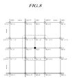
- FIG. 8 is a view for describing the sensing nodes for detecting the coordinate, and the sensing nodes for detecting the pressure of the touch sensing system 100 according to an exemplary embodiment.
- the sensor node corresponding to the detected coordinate is an N(i,j) which is a sensor node defined by a crossing of the L1(i) and the L2(j).
- the main line may be one of the L1(i) and the L2(j).
- At least one of the peripheral sensor nodes N(i-1,j-1), N(i-1,j), N(i-1, j+1), N(i,j-1), N(i, j+1), N(i+1,j-1), N(i+1,j) and N(i+1, j+1) of the sensor node corresponding to the detected coordinate may be sensed for detecting the pressure.
- the adjacent line may include at lease one of L1(i-1), L1(i+1), L2(j-1) and L2(j+1).
- FIG. 9 is a view illustrating the driving pulse for detecting the coordinate and the driving pulse for detecting the pressure of the touch sensing system 100 according to an exemplary embodiment.
- the touch sensing system 100 detects the coordinate first, and performes the pressure detection by using the coordinate detection result.
- the driving pulses are sequentially provided to each of the m number of first lines L1(1) to L1(m) during a first line driving period, and the driving pulses are sequentially provided to each of the n number of second lines L2(1) to L2(n) during a second line driving period.
- the driving pulses are sequentially provided to each of the m number of first lines L1(1) to L1(m) during the first line driving period, the driving pulse is provided to an ith first line, the signal (i.e., the coordinate detecting reception signal) is received throuth the antenna 120, and then the driving pulse is provided to the next (i+1)th first line.
- the signal i.e., the coordinate detecting reception signal
- the driving pulses are sequentially provided to each of the n number of second lines L2(1) to L2(n) during the second line driving period, the driving pulse is provided to a jth second line, the signal (i.e., the coordinate detecting reception signal) is received throuth the antenna 120, and then the driving pulse is provided to the next (j+1)th second line.
- the coordinate is detected during or after the first line driving period and the second line driving period.
- one line L1(2) among the m number of first lines L1(1) to L1(m) is a line corresponding to a first element of the detected coordinate
- one line L2(2) among the n number of second lines L2(1) to L2(n) is a line corresponding to a second element of the detected coordinate.
- the L1(2) and the L2(2) corresponding to the first element and the second element of the detected coordinate are the main lines.
- the pressure may be detected by sequentially driving the L1(1), L1(3) and L2(1) corresponding to the adjacent lines adjacent to the main lines, i.e., the L1(2) and L2(2).
- a sensing time may decrease, a calculation amount according to the pressure detection may decrease, an Analog to Digital (A/D) converting limit of each of the sensor nodes may be overcome, a memory needed in sensing may decrease, ultimately, a touch sensing time may decrease, and thus a performance of the display apparatus may increase.
- A/D Analog to Digital
- an accuracy of the pressure detection result may increase by increasing the sampling number for detecting the pressure in correspondence to the decrease of the sensing time, in a scope wherein the whole touch sensing time may be decreased.
- FIG. 10 is a view illustrating the method for detecting the coordinate of the touch sensing system 100 according to an exemplary embodiment.
- the touch processor 130 may calculate the signal strength of the coordinate detecting reception signal received through the antenna 120, and compare the signal strengths of each of the coordinate detecting reception signals to detect the coordinate (x,y) of the point where the pen 140 touches the screen. At this time, the stronger the signal strength is, the nearer the line is to the touched point.
- the touch processor 130 may calculate the signal strength from the total value of the digital values converted by the predetermined coordinate detecting sampling number (e.g., 500 to 1024 numbers) in the portion of the signal corresponding to the coordinate detecting section, based on a clock of the driving pulse, with respect to each of the coordinate detecting reception signals received through the antenna 120, compare the signal strength calculated with respect to each of the pressure detecting reception signals received through the antenna 120, and detect the coordinate of the point where the pen 140 touches the screen according to the comparison result.
- the predetermined coordinate detecting sampling number e.g., 500 to 1024 numbers
- FIG. 11 is a view illustrating the method for detecting the pressure of the touch sensing system according to an exemplary embodiment.
- the touch processor 130 may calculate the phase difference in comparison to the reference signal with respect to each of the pressure detecting reception signals received through the antenna 120 to detect the pressure of the pen 140 touching the screen based on the calculation result.
- the touch processor 130 may calculate the phase differences in comparison to the reference signal from the total value of the digital values converted by the predetermined pressure detecting sampling number in the portion of the signal corresponding to the pressure detecting section, based on the internal clock of the driving pulse and the reference signal without a phase delay, with respect to each of the pressure detecting reception signals received through the antenna 120, and may detect the pressure of the pen 140 touching the screen based on the phase difference calculated with respect to each of the pressure detecting reception signals received through the antenna 120.
- the sampling number for detecting the presure is set to be increased in correspondence to the decrease of the number of the sensor node for detecting the pressure, therefore the touch sensing time may decrease as much as possible and the pressure may be accurately detected.
- the above-mentioned touch sensing system 100 may be included in a display apparatus such as a Liquid Crystal Display (LCD) apparatus, an Organic Light Emitting Diode (OLED) display apparatus, a Plasma Display Panel (PDP), etc.
- a display apparatus such as a Liquid Crystal Display (LCD) apparatus, an Organic Light Emitting Diode (OLED) display apparatus, a Plasma Display Panel (PDP), etc.
- LCD Liquid Crystal Display
- OLED Organic Light Emitting Diode
- PDP Plasma Display Panel
- the display apparatus is described with reference to FIGs. 12 to 15 .
- FIG. 12 is a view schematically illustrating a display apparatus 1200 according to an exemplary embodiment.
- the display apparatus 1200 includes a display panel 1220, a touch sensor 1210 including the first lines L1 and the second lines L2 formed in the crossing directions and the antenna 120 formed at the peripheral are of the first lines L1 and the second lines L2, a touch processor 1230 performing the first touch process by receiving the signal, with respect to the driving pulses applied to each of the first lines L1 and the second lines L2, through the antenna 120, and then performing the second touch process by sequentially applying the driving pulses to each of two or more selected lines among the first lines L1 and the second lines L2 and receiving the signal through the antenna 120, etc.
- the touch processor 1230 shown in FIG. 12 is preferably identical to the above-mentioned touch processor 130 but can have some variations as needed.
- the antenna 120 may be formed or disposed on the touch screen panel 110 (see FIGS. 1 and 2 ).
- the display apparatus 1200 may include the touch screen panel 110.
- the antenna 120 may be formed or disposed the outside of the touch screen panel 110.
- the first lines L1 and the second lines L2 may be formed on the touch screen panel 110, and the touch screen panel 110 may be attached on the disply panel 1220 included in the display apparatus 1200 in the add-on type.
- the touch screen panel 110 may be included in the dispay panel 1220 in the on-cell type or the in-cell type.
- FIGs. 13 to 15 Three kinds of implementation methods of the above-mentioned touch screen panel 110, that is three kinds of implementation methods of the touch sensor 1210, are illustrated in FIGs. 13 to 15 , respectivley.
- FIGs. 13 to 15 are views illustrating the touch sensor implementation method of the display apparatus 1200 according to an embodiment of the present invention.
- FIG. 13 is a view illustrating a case wherein the touch sensor 1210 such as the first lines L1, the second lines L2 and so on is formed in the touch screen panel 110, and the touch screen panel 110 is attached to the display panel 1220 in the add-on type.
- the touch sensor 1210 such as the first lines L1, the second lines L2 and so on is formed in the touch screen panel 110, and the touch screen panel 110 is attached to the display panel 1220 in the add-on type.
- a cell 1330 is formed between the upper glass 1320b and the lower glass 1320a, a lower polarizer 1310a is formed under the lower glass 1320a, and an upper polarizer 1310b is formed on the upper glass 1320b.
- the cell 1330 may be a liquid crystal layer of the LCD apparatus or an organic layer of the OLED display apparatus.
- the touch screen panel 110 including the touch sensor 1210 such as the first lines L1, the second lines L2 and so on is attached on the display panel 1220 through an air layer or a bonding material.
- an Optical Clear Resin (OCR) or an Optically Clear Adhesive (OCA) may be used as the bonding material.
- FIG. 14 is a view illustrating a case wherein the touch sensor 1210 such as the first lines L1, the second lines L2 and so on is formed in the touch screen panel 110, and the touch screen panel 110 is included in the display panel 1220 in the on cell type.
- the touch sensor 1210 such as the first lines L1, the second lines L2 and so on is formed in the touch screen panel 110, and the touch screen panel 110 is included in the display panel 1220 in the on cell type.
- a cell 1430 is formed between an upper glass 1420b and a lower glass 1420a.
- the lower glass 1420a, the cell 1430 and the upper glass 1420b may be referred to as a "display".
- a lower polarizer 1410a is formed under the lower glass 1420b, and the touch screen panel 110 including the touch sensor 1210 such as the first lines L1, the second lines L2 and so on is included between the upper glass 1420b and the upper polarizer 1410b.
- the touch sensor 1210 such as the first lines L1, second lines L2 and so on is thin-film-deposited on the upper glass 1420b with an Indium Tin Oxide (ITO) and so on, and thus the touch screen panel 110 is included between the upper glass 1420b and the upper polarizer 1410b.
- ITO Indium Tin Oxide
- the touch sensor 1210 is disposed on the "display" including the lower glass 1420a, the cell 1430 and the upper glass 1420b.
- the cell 1430 may be the liquid crystal layer of the LCD apparatus or the organic layer of the OLED display apparatus.
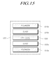
- FIG. 15 is a view illustrating a case wherein the touch sensor 1210 such as the first lines L1, the second lines L2 and so on is included in the display panel 1220 in the in cell type.
- a cell 1530 is formed between an upper glass 1520b and a lower glass 1520a.
- the lower glass 1520a, the cell 1530 and the upper glass 1520b may be referred to as the "display".
- the touch sensor 1210 such as the first lines L1, second lines L2 and so on is formed in the cell 1530. That is, the touch sensor 1210 such as the first lines L1, the second lines L2 and so on may be thin-film-deposited on the lower glass 1520a, which may be a Thin Film Transistor (TFT) array substrate, with the ITO and so on along with the TFT.
- TFT Thin Film Transistor
- a lower polarizer 1510a is formed under the lower glass 1520a, and an upper polarizer 1510b is formed on the upper glass 1520b.
- the touch sensor 1210 is disposed in the "display" including the lower glass 1510a, the cell 1530 and the upper glass 1520b.
- the cell 1530 may be the liquid crystal layer of the LCD apparatus or the organic layer of the OLED display apparatus.
- the present invention there is the effect of providing the combined shape of touch sensing structure for effectively providing the different kinds of the touch modes, without inclusion of the additional touch sensing structure according to each of the different kinds of the touch modes such as the finger touch mode and the pen touch mode, and the touch sensing system 100 and the display apparatus 1200 performing a sensing driving by using the combined shape of touch sensing structure.
- the touch sensing system 100 and the display apparatus 1200 capable of sensing (specially, the pen touch sensing) the touch at high speed, and decreasing the calculation amount and a memory space for the touch sensing.
Landscapes
- Engineering & Computer Science (AREA)
- General Engineering & Computer Science (AREA)
- Theoretical Computer Science (AREA)
- Physics & Mathematics (AREA)
- Human Computer Interaction (AREA)
- General Physics & Mathematics (AREA)
- Electromagnetism (AREA)
- Computer Networks & Wireless Communication (AREA)
- Position Input By Displaying (AREA)
Applications Claiming Priority (1)
| Application Number | Priority Date | Filing Date | Title |
|---|---|---|---|
| KR1020130122328A KR102125404B1 (ko) | 2013-10-15 | 2013-10-15 | 터치감지시스템 및 표시장치 |
Publications (1)
| Publication Number | Publication Date |
|---|---|
| EP2863294A1 true EP2863294A1 (de) | 2015-04-22 |
Family
ID=51392105
Family Applications (1)
| Application Number | Title | Priority Date | Filing Date |
|---|---|---|---|
| EP20140181885 Withdrawn EP2863294A1 (de) | 2013-10-15 | 2014-08-22 | Berührungsempfindliches System und Anzeigevorrichtung |
Country Status (5)
| Country | Link |
|---|---|
| US (1) | US9916049B2 (de) |
| EP (1) | EP2863294A1 (de) |
| JP (2) | JP5902245B2 (de) |
| KR (1) | KR102125404B1 (de) |
| CN (1) | CN104571745B (de) |
Families Citing this family (17)
| Publication number | Priority date | Publication date | Assignee | Title |
|---|---|---|---|---|
| CN104020877B (zh) * | 2014-05-21 | 2017-07-21 | 上海天马微电子有限公司 | 电感触摸屏及其驱动检测方法、坐标输入装置 |
| KR102340937B1 (ko) * | 2015-07-31 | 2021-12-20 | 엘지디스플레이 주식회사 | 스타일러스 펜, 및 터치 센싱 시스템과 그 구동방법 |
| CN105955543B (zh) * | 2016-06-01 | 2019-03-01 | 京东方科技集团股份有限公司 | 显示基板和显示装置 |
| KR101819517B1 (ko) * | 2016-08-17 | 2018-01-17 | 엘지전자 주식회사 | 입력 디바이스 및 그 제어 방법 |
| KR102565297B1 (ko) * | 2016-10-17 | 2023-08-10 | 엘지디스플레이 주식회사 | 터치 표시 장치, 터치 시스템, 터치 마스터 및 통신 방법 |
| KR102568925B1 (ko) * | 2016-10-25 | 2023-08-22 | 엘지디스플레이 주식회사 | 터치센서를 구비하는 표시장치 및 그에 대한 터치감지방법 |
| KR20180080739A (ko) * | 2017-01-04 | 2018-07-13 | 삼성디스플레이 주식회사 | 터치 센서 및 이를 포함하는 터치 센싱 시스템 |
| CN107479776B (zh) * | 2017-08-03 | 2020-07-24 | 京东方科技集团股份有限公司 | 压感检测电路及其驱动方法、电子装置 |
| KR102349419B1 (ko) * | 2017-09-25 | 2022-01-10 | 삼성전자 주식회사 | 터치 스크린 컨트롤러, 이를 포함하는 터치 스크린 시스템 및 터치 스크린 컨트롤러의 동작방법 |
| KR102468750B1 (ko) * | 2017-12-29 | 2022-11-18 | 엘지디스플레이 주식회사 | 터치표시장치, 터치시스템, 터치구동회로, 펜 및 펜 센싱 방법 |
| KR102170298B1 (ko) * | 2018-10-04 | 2020-10-26 | 주식회사 하이딥 | 터치 장치 및 이의 터치 검출 방법 |
| WO2020013453A1 (ko) * | 2018-07-09 | 2020-01-16 | 주식회사 하이딥 | 터치 장치 및 이의 터치 검출 방법 |
| US11886656B2 (en) * | 2019-04-10 | 2024-01-30 | Hideep Inc. | Electronic device and control method therefor |
| KR102764364B1 (ko) * | 2019-06-12 | 2025-02-07 | 주식회사 하이딥 | 터치 장치 및 이의 터치 검출 방법 |
| EP3792735B1 (de) | 2019-09-16 | 2022-02-09 | Microsoft Technology Licensing, LLC | Eingabestiftgeschwindigkeit |
| KR20230083641A (ko) * | 2021-12-03 | 2023-06-12 | 주식회사 엘엑스세미콘 | 터치 센싱 장치 및 터치 센싱 방법 |
| KR20250064721A (ko) * | 2023-11-02 | 2025-05-12 | 삼성디스플레이 주식회사 | 전자 장치 |
Citations (7)
| Publication number | Priority date | Publication date | Assignee | Title |
|---|---|---|---|---|
| US5905489A (en) * | 1996-02-16 | 1999-05-18 | Sharp Kabushiki Kaisha | Coordinate input device |
| US6417846B1 (en) * | 2000-02-02 | 2002-07-09 | Lee Si-Ken | Multifunction input device |
| JP2008152640A (ja) * | 2006-12-19 | 2008-07-03 | Sony Corp | 座標入力装置及び座標入力システム |
| KR20110057385A (ko) * | 2009-11-24 | 2011-06-01 | 주식회사 윈터치 | 터치패드 기능을 구비한 타블렛 |
| CN102253774A (zh) * | 2010-05-21 | 2011-11-23 | 汉王科技股份有限公司 | 具备消除感应信号相互干扰功能的信息输入装置及方法 |
| US20130076670A1 (en) * | 2011-09-23 | 2013-03-28 | Kye Systems Corp. | Dual-mode tablet and detecting and switching method for input signals thereof |
| EP2629183A2 (de) * | 2012-02-16 | 2013-08-21 | Samsung Display Co., Ltd. | Verfahren zum Betreiben einer Berührungstafel, Berührungstafel und Anzeigevorrichtung |
Family Cites Families (17)
| Publication number | Priority date | Publication date | Assignee | Title |
|---|---|---|---|---|
| US7289109B2 (en) * | 2000-09-26 | 2007-10-30 | Denny Jaeger | Method and apparatus for detecting actuation of a controller device on a touch screen |
| JP2006163798A (ja) * | 2004-12-07 | 2006-06-22 | Wacom Co Ltd | 座標指示器、および、座標入力装置 |
| US20060262106A1 (en) * | 2005-05-20 | 2006-11-23 | Lg Electronics Inc. | Pen input device with data storage |
| JP4709674B2 (ja) * | 2006-03-23 | 2011-06-22 | 株式会社ワコム | 位置検出装置及びコンピュータ |
| US8134542B2 (en) * | 2006-12-20 | 2012-03-13 | 3M Innovative Properties Company | Untethered stylus employing separate communication and power channels |
| JP5886489B2 (ja) * | 2009-09-21 | 2016-03-16 | 株式会社ワコム | 位置検出装置 |
| JP5466908B2 (ja) | 2009-09-21 | 2014-04-09 | 株式会社ワコム | センサ基板および位置検出装置 |
| US9632628B2 (en) * | 2009-10-23 | 2017-04-25 | Atmel Corporation | Interdigitated touchscreen electrodes |
| JP5427070B2 (ja) * | 2010-03-05 | 2014-02-26 | 株式会社ワコム | 位置検出装置 |
| US8922527B2 (en) * | 2012-02-15 | 2014-12-30 | Cypress Semiconductor Corporation | Multi-purpose stylus antenna |
| US9213455B2 (en) * | 2012-10-17 | 2015-12-15 | Atmel Corporation | Stylus with resonant circuit |
| DE102013201009A1 (de) | 2013-01-23 | 2014-07-24 | Siemens Aktiengesellschaft | Verfahren und Vorrichtung zur Durchführung einer Positronen-Emissions-Tomographie |
| KR102111032B1 (ko) * | 2013-08-14 | 2020-05-15 | 삼성디스플레이 주식회사 | 터치 감지 표시 장치 |
| KR102111274B1 (ko) * | 2013-09-26 | 2020-05-15 | 엘지디스플레이 주식회사 | 터치 센싱 시스템과 그 구동 방법 |
| KR102126531B1 (ko) * | 2013-09-27 | 2020-06-24 | 엘지디스플레이 주식회사 | 터치 센싱 시스템과 그 구동 방법 |
| US9459367B2 (en) * | 2013-10-02 | 2016-10-04 | Synaptics Incorporated | Capacitive sensor driving technique that enables hybrid sensing or equalization |
| KR102087830B1 (ko) * | 2013-11-01 | 2020-04-14 | 엘지디스플레이 주식회사 | 터치 센싱 시스템과 그 구동 방법 |
-
2013
- 2013-10-15 KR KR1020130122328A patent/KR102125404B1/ko active Active
-
2014
- 2014-07-10 JP JP2014142342A patent/JP5902245B2/ja active Active
- 2014-08-15 US US14/460,992 patent/US9916049B2/en active Active
- 2014-08-22 EP EP20140181885 patent/EP2863294A1/de not_active Withdrawn
- 2014-10-10 CN CN201410531165.1A patent/CN104571745B/zh not_active Expired - Fee Related
-
2016
- 2016-03-08 JP JP2016044176A patent/JP6153042B2/ja not_active Expired - Fee Related
Patent Citations (7)
| Publication number | Priority date | Publication date | Assignee | Title |
|---|---|---|---|---|
| US5905489A (en) * | 1996-02-16 | 1999-05-18 | Sharp Kabushiki Kaisha | Coordinate input device |
| US6417846B1 (en) * | 2000-02-02 | 2002-07-09 | Lee Si-Ken | Multifunction input device |
| JP2008152640A (ja) * | 2006-12-19 | 2008-07-03 | Sony Corp | 座標入力装置及び座標入力システム |
| KR20110057385A (ko) * | 2009-11-24 | 2011-06-01 | 주식회사 윈터치 | 터치패드 기능을 구비한 타블렛 |
| CN102253774A (zh) * | 2010-05-21 | 2011-11-23 | 汉王科技股份有限公司 | 具备消除感应信号相互干扰功能的信息输入装置及方法 |
| US20130076670A1 (en) * | 2011-09-23 | 2013-03-28 | Kye Systems Corp. | Dual-mode tablet and detecting and switching method for input signals thereof |
| EP2629183A2 (de) * | 2012-02-16 | 2013-08-21 | Samsung Display Co., Ltd. | Verfahren zum Betreiben einer Berührungstafel, Berührungstafel und Anzeigevorrichtung |
Also Published As
| Publication number | Publication date |
|---|---|
| CN104571745A (zh) | 2015-04-29 |
| US20150103039A1 (en) | 2015-04-16 |
| JP2016105334A (ja) | 2016-06-09 |
| KR102125404B1 (ko) | 2020-06-22 |
| JP5902245B2 (ja) | 2016-04-13 |
| JP6153042B2 (ja) | 2017-06-28 |
| JP2015079487A (ja) | 2015-04-23 |
| KR20150043670A (ko) | 2015-04-23 |
| CN104571745B (zh) | 2018-06-01 |
| US9916049B2 (en) | 2018-03-13 |
Similar Documents
| Publication | Publication Date | Title |
|---|---|---|
| EP2863294A1 (de) | Berührungsempfindliches System und Anzeigevorrichtung | |
| EP2960759B1 (de) | Berührungstafel | |
| US8686969B2 (en) | Input apparatus with integrated detection sections of electromagnetic type and capacitive type | |
| EP2184666B1 (de) | Mehrpunkt-Messverfahren für einen kapazitiven Berührungsbildschirm | |
| KR101441396B1 (ko) | 입력 시스템 및 이를 이용한 터치 검출 방법 | |
| TWI485579B (zh) | 指示體、位置檢測裝置及位置檢測方法 | |
| JP5839173B2 (ja) | タッチセンサ装置及び電子機器 | |
| US9098131B2 (en) | Input system with stylus pen having two coils and elastic member | |
| JP6472196B2 (ja) | センサ信号処理回路及びセンサ信号処理方法 | |
| EP3035168A2 (de) | Stifteingabevorrichtung, verfahren zur korrektur von eingabekoordinaten dafür und elektronische vorrichtung zur unterstützung davon | |
| US20100252335A1 (en) | Capacitive Touchscreen or Touchpad for Finger and Active Stylus | |
| US20150070297A1 (en) | Control method for touch panel | |
| KR20170090968A (ko) | 능동형 스타일러스 펜과 그를 포함한 터치 센싱 시스템 | |
| TWI509531B (zh) | Apparatus for identifying touch signal and method thereof | |
| TW200921054A (en) | Position sensor and display device | |
| US10254896B2 (en) | Display with case electrically connected to ground | |
| CN102880338A (zh) | 触控显示设备 | |
| TWI579738B (zh) | 位置檢測裝置及位置檢測方法 | |
| KR20150076774A (ko) | 터치시스템, 터치패널 및 표시장치 | |
| US10055033B2 (en) | Active capacitive pen, and touch detection and feedback driving methods therefor | |
| US11899876B2 (en) | Mutual capacitive touch-sensitive apparatus and method applying inverse signals to electrodes | |
| CN102436333B (zh) | 兼容电容定位和电磁定位的输入装置及其输入方法 | |
| US9519386B2 (en) | Input device and electronic device including the same | |
| US11592932B2 (en) | Position detection in rollable displays | |
| CN202736007U (zh) | 一种互电容式触摸屏和fpc |
Legal Events
| Date | Code | Title | Description |
|---|---|---|---|
| PUAI | Public reference made under article 153(3) epc to a published international application that has entered the european phase |
Free format text: ORIGINAL CODE: 0009012 |
|
| 17P | Request for examination filed |
Effective date: 20140822 |
|
| AK | Designated contracting states |
Kind code of ref document: A1 Designated state(s): AL AT BE BG CH CY CZ DE DK EE ES FI FR GB GR HR HU IE IS IT LI LT LU LV MC MK MT NL NO PL PT RO RS SE SI SK SM TR |
|
| AX | Request for extension of the european patent |
Extension state: BA ME |
|
| R17P | Request for examination filed (corrected) |
Effective date: 20151021 |
|
| RBV | Designated contracting states (corrected) |
Designated state(s): AL AT BE BG CH CY CZ DE DK EE ES FI FR GB GR HR HU IE IS IT LI LT LU LV MC MK MT NL NO PL PT RO RS SE SI SK SM TR |
|
| STAA | Information on the status of an ep patent application or granted ep patent |
Free format text: STATUS: EXAMINATION IS IN PROGRESS |
|
| 17Q | First examination report despatched |
Effective date: 20180522 |
|
| STAA | Information on the status of an ep patent application or granted ep patent |
Free format text: STATUS: THE APPLICATION IS DEEMED TO BE WITHDRAWN |
|
| 18D | Application deemed to be withdrawn |
Effective date: 20221201 |