EP2865973A1 - Paroi isolante, boîte isolante et procédé de fabrication pour celles-ci - Google Patents
Paroi isolante, boîte isolante et procédé de fabrication pour celles-ci Download PDFInfo
- Publication number
- EP2865973A1 EP2865973A1 EP20130806834 EP13806834A EP2865973A1 EP 2865973 A1 EP2865973 A1 EP 2865973A1 EP 20130806834 EP20130806834 EP 20130806834 EP 13806834 A EP13806834 A EP 13806834A EP 2865973 A1 EP2865973 A1 EP 2865973A1
- Authority
- EP
- European Patent Office
- Prior art keywords
- heat
- cell
- insulating
- hole
- urethane
- Prior art date
- Legal status (The legal status is an assumption and is not a legal conclusion. Google has not performed a legal analysis and makes no representation as to the accuracy of the status listed.)
- Granted
Links
Images









Classifications
-
- F—MECHANICAL ENGINEERING; LIGHTING; HEATING; WEAPONS; BLASTING
- F16—ENGINEERING ELEMENTS AND UNITS; GENERAL MEASURES FOR PRODUCING AND MAINTAINING EFFECTIVE FUNCTIONING OF MACHINES OR INSTALLATIONS; THERMAL INSULATION IN GENERAL
- F16L—PIPES; JOINTS OR FITTINGS FOR PIPES; SUPPORTS FOR PIPES, CABLES OR PROTECTIVE TUBING; MEANS FOR THERMAL INSULATION IN GENERAL
- F16L59/00—Thermal insulation in general
- F16L59/02—Shape or form of insulating materials, with or without coverings integral with the insulating materials
- F16L59/029—Shape or form of insulating materials, with or without coverings integral with the insulating materials layered
-
- F—MECHANICAL ENGINEERING; LIGHTING; HEATING; WEAPONS; BLASTING
- F25—REFRIGERATION OR COOLING; COMBINED HEATING AND REFRIGERATION SYSTEMS; HEAT PUMP SYSTEMS; MANUFACTURE OR STORAGE OF ICE; LIQUEFACTION SOLIDIFICATION OF GASES
- F25D—REFRIGERATORS; COLD ROOMS; ICE-BOXES; COOLING OR FREEZING APPARATUS NOT OTHERWISE PROVIDED FOR
- F25D23/00—General constructional features
- F25D23/08—Parts formed wholly or mainly of plastics materials
-
- B—PERFORMING OPERATIONS; TRANSPORTING
- B29—WORKING OF PLASTICS; WORKING OF SUBSTANCES IN A PLASTIC STATE IN GENERAL
- B29C—SHAPING OR JOINING OF PLASTICS; SHAPING OF MATERIAL IN A PLASTIC STATE, NOT OTHERWISE PROVIDED FOR; AFTER-TREATMENT OF THE SHAPED PRODUCTS, e.g. REPAIRING
- B29C44/00—Shaping by internal pressure generated in the material, e.g. swelling or foaming ; Producing porous or cellular expanded plastics articles
- B29C44/02—Shaping by internal pressure generated in the material, e.g. swelling or foaming ; Producing porous or cellular expanded plastics articles for articles of definite length, i.e. discrete articles
- B29C44/12—Incorporating or moulding on preformed parts, e.g. inserts or reinforcements
- B29C44/1228—Joining preformed parts by the expanding material
- B29C44/1233—Joining preformed parts by the expanding material the preformed parts being supported during expanding
-
- B—PERFORMING OPERATIONS; TRANSPORTING
- B29—WORKING OF PLASTICS; WORKING OF SUBSTANCES IN A PLASTIC STATE IN GENERAL
- B29C—SHAPING OR JOINING OF PLASTICS; SHAPING OF MATERIAL IN A PLASTIC STATE, NOT OTHERWISE PROVIDED FOR; AFTER-TREATMENT OF THE SHAPED PRODUCTS, e.g. REPAIRING
- B29C44/00—Shaping by internal pressure generated in the material, e.g. swelling or foaming ; Producing porous or cellular expanded plastics articles
- B29C44/34—Auxiliary operations
- B29C44/58—Moulds
- B29C44/588—Moulds with means for venting, e.g. releasing foaming gas
-
- B—PERFORMING OPERATIONS; TRANSPORTING
- B32—LAYERED PRODUCTS
- B32B—LAYERED PRODUCTS, i.e. PRODUCTS BUILT-UP OF STRATA OF FLAT OR NON-FLAT, e.g. CELLULAR OR HONEYCOMB, FORM
- B32B1/00—Layered products having a non-planar shape
-
- B—PERFORMING OPERATIONS; TRANSPORTING
- B32—LAYERED PRODUCTS
- B32B—LAYERED PRODUCTS, i.e. PRODUCTS BUILT-UP OF STRATA OF FLAT OR NON-FLAT, e.g. CELLULAR OR HONEYCOMB, FORM
- B32B5/00—Layered products characterised by the non- homogeneity or physical structure, i.e. comprising a fibrous, filamentary, particulate or foam layer; Layered products characterised by having a layer differing constitutionally or physically in different parts
- B32B5/18—Layered products characterised by the non- homogeneity or physical structure, i.e. comprising a fibrous, filamentary, particulate or foam layer; Layered products characterised by having a layer differing constitutionally or physically in different parts characterised by features of a layer of foamed material
- B32B5/20—Layered products characterised by the non- homogeneity or physical structure, i.e. comprising a fibrous, filamentary, particulate or foam layer; Layered products characterised by having a layer differing constitutionally or physically in different parts characterised by features of a layer of foamed material foamed in situ
-
- C—CHEMISTRY; METALLURGY
- C08—ORGANIC MACROMOLECULAR COMPOUNDS; THEIR PREPARATION OR CHEMICAL WORKING-UP; COMPOSITIONS BASED THEREON
- C08J—WORKING-UP; GENERAL PROCESSES OF COMPOUNDING; AFTER-TREATMENT NOT COVERED BY SUBCLASSES C08B, C08C, C08F, C08G or C08H
- C08J9/00—Working-up of macromolecular substances to porous or cellular articles or materials; After-treatment thereof
- C08J9/0004—Use of compounding ingredients, the chemical constitution of which is unknown, broadly defined, or irrelevant
- C08J9/0009—Phase change materials
-
- F—MECHANICAL ENGINEERING; LIGHTING; HEATING; WEAPONS; BLASTING
- F16—ENGINEERING ELEMENTS AND UNITS; GENERAL MEASURES FOR PRODUCING AND MAINTAINING EFFECTIVE FUNCTIONING OF MACHINES OR INSTALLATIONS; THERMAL INSULATION IN GENERAL
- F16L—PIPES; JOINTS OR FITTINGS FOR PIPES; SUPPORTS FOR PIPES, CABLES OR PROTECTIVE TUBING; MEANS FOR THERMAL INSULATION IN GENERAL
- F16L59/00—Thermal insulation in general
- F16L59/06—Arrangements using an air layer or vacuum
-
- F—MECHANICAL ENGINEERING; LIGHTING; HEATING; WEAPONS; BLASTING
- F25—REFRIGERATION OR COOLING; COMBINED HEATING AND REFRIGERATION SYSTEMS; HEAT PUMP SYSTEMS; MANUFACTURE OR STORAGE OF ICE; LIQUEFACTION SOLIDIFICATION OF GASES
- F25D—REFRIGERATORS; COLD ROOMS; ICE-BOXES; COOLING OR FREEZING APPARATUS NOT OTHERWISE PROVIDED FOR
- F25D23/00—General constructional features
- F25D23/06—Walls
-
- F—MECHANICAL ENGINEERING; LIGHTING; HEATING; WEAPONS; BLASTING
- F25—REFRIGERATION OR COOLING; COMBINED HEATING AND REFRIGERATION SYSTEMS; HEAT PUMP SYSTEMS; MANUFACTURE OR STORAGE OF ICE; LIQUEFACTION SOLIDIFICATION OF GASES
- F25D—REFRIGERATORS; COLD ROOMS; ICE-BOXES; COOLING OR FREEZING APPARATUS NOT OTHERWISE PROVIDED FOR
- F25D23/00—General constructional features
- F25D23/06—Walls
- F25D23/062—Walls defining a cabinet
- F25D23/064—Walls defining a cabinet formed by moulding, e.g. moulding in situ
-
- B—PERFORMING OPERATIONS; TRANSPORTING
- B29—WORKING OF PLASTICS; WORKING OF SUBSTANCES IN A PLASTIC STATE IN GENERAL
- B29K—INDEXING SCHEME ASSOCIATED WITH SUBCLASSES B29B, B29C OR B29D, RELATING TO MOULDING MATERIALS OR TO MATERIALS FOR MOULDS, REINFORCEMENTS, FILLERS OR PREFORMED PARTS, e.g. INSERTS
- B29K2105/00—Condition, form or state of moulded material or of the material to be shaped
- B29K2105/04—Condition, form or state of moulded material or of the material to be shaped cellular or porous
- B29K2105/045—Condition, form or state of moulded material or of the material to be shaped cellular or porous with open cells
-
- B—PERFORMING OPERATIONS; TRANSPORTING
- B32—LAYERED PRODUCTS
- B32B—LAYERED PRODUCTS, i.e. PRODUCTS BUILT-UP OF STRATA OF FLAT OR NON-FLAT, e.g. CELLULAR OR HONEYCOMB, FORM
- B32B2266/00—Composition of foam
- B32B2266/02—Organic
- B32B2266/0214—Materials belonging to B32B27/00
- B32B2266/0278—Polyurethane
-
- B—PERFORMING OPERATIONS; TRANSPORTING
- B32—LAYERED PRODUCTS
- B32B—LAYERED PRODUCTS, i.e. PRODUCTS BUILT-UP OF STRATA OF FLAT OR NON-FLAT, e.g. CELLULAR OR HONEYCOMB, FORM
- B32B2307/00—Properties of the layers or laminate
- B32B2307/30—Properties of the layers or laminate having particular thermal properties
- B32B2307/304—Insulating
-
- B—PERFORMING OPERATIONS; TRANSPORTING
- B32—LAYERED PRODUCTS
- B32B—LAYERED PRODUCTS, i.e. PRODUCTS BUILT-UP OF STRATA OF FLAT OR NON-FLAT, e.g. CELLULAR OR HONEYCOMB, FORM
- B32B2607/00—Walls, panels
-
- C—CHEMISTRY; METALLURGY
- C08—ORGANIC MACROMOLECULAR COMPOUNDS; THEIR PREPARATION OR CHEMICAL WORKING-UP; COMPOSITIONS BASED THEREON
- C08J—WORKING-UP; GENERAL PROCESSES OF COMPOUNDING; AFTER-TREATMENT NOT COVERED BY SUBCLASSES C08B, C08C, C08F, C08G or C08H
- C08J2375/00—Characterised by the use of polyureas or polyurethanes; Derivatives of such polymers
- C08J2375/04—Polyurethanes
-
- F—MECHANICAL ENGINEERING; LIGHTING; HEATING; WEAPONS; BLASTING
- F25—REFRIGERATION OR COOLING; COMBINED HEATING AND REFRIGERATION SYSTEMS; HEAT PUMP SYSTEMS; MANUFACTURE OR STORAGE OF ICE; LIQUEFACTION SOLIDIFICATION OF GASES
- F25D—REFRIGERATORS; COLD ROOMS; ICE-BOXES; COOLING OR FREEZING APPARATUS NOT OTHERWISE PROVIDED FOR
- F25D2201/00—Insulation
- F25D2201/10—Insulation with respect to heat
- F25D2201/12—Insulation with respect to heat using an insulating packing material
- F25D2201/126—Insulation with respect to heat using an insulating packing material of cellular type
- F25D2201/1262—Insulation with respect to heat using an insulating packing material of cellular type with open cells
-
- Y—GENERAL TAGGING OF NEW TECHNOLOGICAL DEVELOPMENTS; GENERAL TAGGING OF CROSS-SECTIONAL TECHNOLOGIES SPANNING OVER SEVERAL SECTIONS OF THE IPC; TECHNICAL SUBJECTS COVERED BY FORMER USPC CROSS-REFERENCE ART COLLECTIONS [XRACs] AND DIGESTS
- Y10—TECHNICAL SUBJECTS COVERED BY FORMER USPC
- Y10T—TECHNICAL SUBJECTS COVERED BY FORMER US CLASSIFICATION
- Y10T428/00—Stock material or miscellaneous articles
- Y10T428/23—Sheet including cover or casing
- Y10T428/233—Foamed or expanded material encased
Definitions
- the present invention relates to a heat-insulating wall, and a heat-insulating box and a method for producing the same.
- Patent Literature 1 proposes a technique in which a heat-insulating space of a heat-insulating box is filled with an "open-cell urethane foam" from an air feeding port for blow molding in the heat-insulating box and the urethane foam is foamed, followed by evacuating the inside of the heat-insulating box to vacuum using a vacuum exhaust apparatus connected to the air feeding port.
- the "open-cell” refers to a structure in which respective cells communicate with one another.
- the “closed-cell” refers to a structure in which respective cells are independent and do not communicate with one another.
- the present inventors have found that the above-mentioned previous technique has the following problem. That is, the above-mentioned previous invention does not indicate a method for uniformly filling a heat-insulating space with an open-cell urethane foam. Thus, the previous invention has the problem that the external appearance of a heat-insulating box is deformed by a non-uniformly filled open-cell urethane foam and a gas released from a closed cell in an open-cell urethane foam.
- the previous invention does not disclose a method for preventing ingress of moisture into a heat-insulating space after the heat-insulating space is filled with an open-cell urethane foam.
- the previous invention has the problem that an open-cell urethane foam is degraded by ingress of moisture, leading to deterioration of heat-insulating performance of a heat-insulating box.
- An object of the present invention is to provide a heat-insulating wall which can resist deformation of an external appearance and deterioration of heat-insulating properties, a heat-insulating housing and a method for producing the same.
- a heat-insulating wall includes: a wall body whose hollow portion is a heat-insulating space; a gas circulation port which is disposed on the wall body and through which the heat-insulating space communicates with the outside; and an open-cell urethane foam of a thermosetting urethane resin with which the heat-insulating space is filled by integral foaming; and a sealing material for sealing the gas circulation port.
- a heat-insulating wall which can resist deformation of an external appearance and deterioration of heat-insulating properties
- a heat-insulating housing and a method for producing the same.
- a heat-insulating wall includes: a wall body whose hollow portion is a heat-insulating space; a gas circulation port which is disposed on the wall body and through which the heat-insulating space communicates with the outside; an open-cell urethane foam of a thermosetting urethane resin with which the heat-insulating space is filled by integral foaming; and a sealing material for sealing the gas circulation port.
- the "gas circulation port” here includes at least one of the later described urethane injection port, air hole and exhaust hole, and the same applies to the following description of the gas circulation port.
- the “sealing material” includes at least one of the later described air hole sealing material, urethane injection port sealing material and exhaust hole sealing material, and the same applies to the following description of the sealing material.
- the gas circulation port through which the heat-insulating space communicates with the outside, can be used as an injection port for injecting a raw material of the open-cell urethane foam and an air discharge port of the heat-insulating space. Consequently, fluidity of air in the heat-insulating space during injection of a raw material and foaming is secured, and therefore the heat-insulating space is uniformly filled with the open-cell urethane foam.
- the gas circulation port into which air penetrates from outside is sealed with the sealing material, and therefore ingress of moisture from the gas circulation port is prevented, so that degradation of the open-cell urethane foam due to moisture is prevented. Further, cells in the open-cell urethane foam continuously communicate with one another. Consequently, deformation of the external appearance of the heat-insulating wall can be prevented, and heat-insulating performance can be improved.
- a heat-insulating wall according to a second aspect of the present invention may be the heat-insulating wall according to the first aspect of the present invention, wherein the open-cell urethane foam includes: a core layer; and a skin layer formed in the vicinity of an interface with the wall body and surrounding the core layer, each of the core layer and the skin layer includes: a plurality of cells; a cell film portion which is formed at a location where the cells are adjacent to one another; a cell skeleton portion which is formed at a location where the cells are adjacent to one another and which is formed in such a manner that a distance between the adjacent cells is greater than a thickness of the cell film portion; a first through-hole formed so as to extend through the cell film portion; and a second through-hole formed so as to extend through the cell skeleton portion, the skin layer contains a larger number of the cell skeleton portions than the core layer, and the plurality of cells communicate with one another through the first through-hole and the second through-hole.
- a heat-insulating box according to a third aspect of the present invention may include one or more of the heat-insulating walls according to the first or second aspect of the present invention, wherein the wall body includes an outer casing and an inner casing stored in the outer casing.
- a heat-insulating box according to a fourth aspect of the present invention may be the heat-insulating box according to the third aspect of the present invention, wherein the gas circulation port includes: an air hole for releasing air from the heat-insulating space in the process of filling the heat-insulating space with the open-cell urethane foam; and a urethane liquid injection port for injecting the raw material of the open-cell urethane foam into the heat-insulating space, and the sealing material includes: an air hole sealing material for sealing the air hole; and a urethane liquid injection port sealing material for sealing the urethane liquid injection port.
- a heat-insulating box according to a fifth aspect of the present invention may be the heat-insulating box according to the fourth aspect of the present invention, wherein the hole size of the air hole is smaller than the hole size of the urethane liquid injection port.
- a heat-insulating box according to a sixth aspect of the present invention may be the heat-insulating box according to the fourth or fifth aspect of the present invention, wherein the air hole is provided in the inner casing, and the urethane liquid injection port is provided in the outer casing.
- the air hole and the urethane liquid injection port can be separately disposed in the inner casing and the outer casing, respectively, so as to secure fluidity of the raw material of the open-cell urethane foam and air.
- a heat-insulating box according to a seventh aspect of the present invention may be the heat-insulating box according to any one of the fourth to sixth aspects of the present invention, wherein the gas circulation port further includes an exhaust hole for evacuating the heat-insulating space, and the sealing material further includes an exhaust hole sealing material for sealing the exhaust hole.
- the heat-insulating space filled with the open-cell urethane foam is evacuated through the exhaust hole to form the heat-insulating space into a vacuum heat-insulating layer, so that the heat-insulating properties of the heat-insulating box can be further improved.
- the exhaust hole is sealed together with the air hole and the urethane liquid injection port to maintain a vacuum degree of the heat-insulating space, so that deterioration of the heat-insulating properties of the heat-insulating box can be suppressed.
- a heat-insulating box according to an eighth aspect of the present invention may be the heat-insulating box according to the seventh aspect of the present invention, wherein the urethane liquid injection port is used also as the exhaust hole.
- sealing of the urethane liquid injection port and sealing of the exhaust hole are performed at the same time, so that the number of man-hours for construction of the heat-insulating box can be reduced.
- a heat-insulating box according to a ninth aspect of the present invention may be the heat-insulating box according to any one of the third to eighth aspects of the present invention, further including a gas adsorbing device disposed in the heat-insulating space.
- the gas adsorbing device exhibits a gas adsorption function to further easily prevent degradation of the open-cell urethane foam.
- the heat-insulating space filled with the open-cell urethane foam is evacuated, the exhaust distance of the open-cell urethane foam is reduced by the gas adsorption function of the gas adsorbing device, so that efficient evacuation can be realized.
- the heat-insulating space is evacuated as described above, a very small amount of residual gas present in the heat-insulating space can be adsorbed to the gas adsorbing device, so that the vacuum degree of the heat-insulating space is easily maintained.
- a heat-insulating box may be one, wherein the gas adsorbing device includes an adsorbent that adsorbs a carbon dioxide gas, and the adsorbent includes ZSM-5 zeolite ion-exchanged with at least one of barium and strontium.
- a method for producing a heat-insulating box includes: forming a heat-insulating space using a wall body; and injecting a raw material of an open-cell urethane foam into the heat-insulating space, wherein the open-cell urethane foam with which the heat-insulating space is filled by integral foaming/molding of the raw material and the wall body includes: a plurality of cells; a cell film portion which is formed at a location where the cells are adjacent to one another; a cell skeleton portion which is formed at a location where the cells are adjacent to one another and which is formed in such a manner that a distance between the adjacent cells is greater than a thickness of the cell film portion; a first through-hole formed so as to extend through the cell film portion; and a second through-hole formed so as to extend through the cell skeleton portion, the plurality of cells communicate with one another through the first through-hole and the second through-hole, and the raw material includes: a plurality of polyol mixture
- the raw material of the open-cell urethane foam when the raw material of the open-cell urethane foam is injected from the gas circulation port into the heat-insulating space, air is discharged from the gas circulation port through which the heat-insulating space communicates with the outside.
- the heat-insulating space can be uniformly filled with the open-cell urethane foam.
- the raw material of the open-cell urethane foam contains a plurality of polyol mixtures of different compositions, a polyisocyanate, a foaming agent and a powder. Consequently, in the open-cell urethane foam, cells, a first through-hole extending through the cell film portion, and a second through-hole extending through the cell skeleton portion are formed. Consequently, cells can be caused to communicate with one another throughout the open-cell urethane foam.
- a method for producing a heat-insulating box according to a twelfth aspect of the present invention may be the method according to the eleventh aspect of the present invention, the method further including sealing with a sealing material the gas circulation port which is disposed on the wall body and through which the heat-insulating space communicates with the outside.
- a method for producing a heat-insulating box according to a thirteenth aspect of the present invention may be the method according to the twelfth aspect of the present invention, wherein the gas circulation port includes: an air hole for releasing air from the heat-insulating space in the process of filling the heat-insulating space with the open-cell urethane foam; and a urethane liquid injection port for injecting the raw material, the sealing material includes: an air hole sealing material for sealing the air hole; and a urethane liquid injection port sealing material for sealing the urethane liquid injection port, and sealing the gas circulation port with the sealing material includes: sealing the air hole with the air hole sealing material after injecting the raw material from the urethane liquid injection port into the heat-insulating space; and sealing the urethane liquid injection port with the urethane liquid injection port sealing material after sealing the air hole.
- the heat-insulating space is discharged from the air hole, so that the heat-insulating space can be uniformly filled with the open-cell urethane foam.
- the heat-insulating space can be airtightly closed, degradation of the open-cell urethane foam by ingress of moisture is prevented.
- a method for producing a heat-insulating box according to a fourteenth aspect of the present invention may be the method according to the thirteenth aspect of the present invention, wherein the gas circulation port further includes an exhaust hole for evacuating the heat-insulating space filled with the open-cell urethane foam, the sealing material further includes an exhaust hole sealing material for sealing the exhaust hole, the method further includes evacuating the heat-insulating space through the exhaust hole after sealing the air hole, and sealing the gas circulation port with the sealing material further includes sealing the exhaust hole with the exhaust hole sealing material after performing the evacuation.
- the heat-insulating space when the heat-insulating space is evacuated from the exhaust hole after the heat-insulating space is filled with the open-cell urethane foam, the heat-insulating space can be formed into a vacuum heat-insulating layer.
- the air hole, the urethane liquid injection port and the exhaust hole are sealed, the vacuum degree of the heat-insulating space can be kept high.
- a method for producing a heat-insulating box according to a fifteenth aspect of the present invention may be the method according to any one of the eleventh to fourteenth aspects of the present invention, the method further including disposing a gas adsorbing device in the heat-insulating space before injecting the raw material.
- the open-cell urethane foam and the gas adsorbing device are provided in the heat-insulating space.
- the gas adsorbing device exhibits a gas adsorption function, so that degradation of the open-cell urethane foam can be prevented.
- the gas adsorbing device adsorbs a gas to reduce the exhaust distance of the open-cell urethane foam, so that efficient evacuation can be realized. Further, the gas adsorbing device adsorbs a very small amount of residual gas present in the heat-insulating space after evacuation, so that the vacuum degree of the heat-insulating space is further easily maintained.
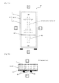
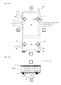
- Fig. 1A is a front view of a refrigerator 20 including a heat-insulating box 21 according to Embodiment 1 of the present invention.
- Fig. 1B is a local sectional view showing a part of the refrigerator 20 taken along line A-A in Fig. 1A .
- the height direction of the refrigerator 20 is a vertical direction
- the width direction of the refrigerator 20 is a horizontal direction
- the thickness direction of the refrigerator 20 is a longitudinal direction.
- the refrigerator 20 includes the heat-insulating box 21, and a door (not illustrated) mounted on the heat-insulating box 21.
- the heat-insulating box 21 is a box-shaped container that is opened at the front, and has an internal space.
- the internal space is partitioned into, for example, a refrigerator compartment 26 on the upper side and a freezer compartment 27 on the lower side by a partition plate 25.
- a single-opening-type or double-opening-type swing door (not illustrated) is attached on the heat-insulating box 21 so as to openably close the refrigerator compartment 26.
- a drawer-type door (not illustrated) is attached on the heat-insulating box 21 so as to openably close the freezer compartment 27 in the longitudinal direction.
- a refrigeration cycle (not illustrated) provided with a compressor, an evaporator and a condenser is attached on the refrigerator 20.
- the internal space of the refrigerator 20 is not necessarily partitioned into the refrigerator compartment 26 and the freezer compartment 27.
- the internal space of the refrigerator 20 may be partitioned by a plurality of partition plates into storage compartments which are used for different purposes (refrigerator compartment, freezer compartment, ice compartment, vegetable compartment and so on).
- the heat-insulating box 21 includes one or more heat-insulating walls.
- the heat-insulating box 21 includes one heat-insulating wall, and therefore the heat-insulating wall has the overall shape of the heat-insulating box 21.
- the box-shaped heat-insulating box 21 may be formed by combining a plurality of heat-insulating walls.
- the heat-insulating box 21 includes a hollow wall body, and an open-cell urethane foam 4 with which the heat-insulating space in the wall body is filled.
- the open-cell urethane foam 4 forms a core material of a heat-insulating layer in the heat-insulating box 21.
- the wall body includes an outer casing 2 and an inner casing 3 stored in the outer casing.
- the outer casing 2 is formed of a metal (e.g. iron)
- the inner casing 3 is formed of a resin such as a hard resin (e.g. ABS (acrylonitrile butadiene styrene) resin).
- both the outer casing 2 and the inner casing 3 may be formed of a metal. Further, both the outer casing 2 and the inner casing 3 may be formed of a resin. A space between the outer casing 2 and the inner casing 3, i.e. a hollow portion in the wall body is used as a heat-insulating space.
- the wall body is not necessarily formed of two components: the outer casing 2 and the inner casing 3 as long as it has a heat-insulating space at the inside thereof.
- the wall body may be formed of one or three or more components.
- a urethane liquid injection port 5 is disposed at each of total four locations: an upper right part, an upper left part, a lower right part and a lower left part of the outer casing 2.
- the urethane liquid injection port 5 is a gas communication port which extends through the back plate of the outer casing 2 to establish communication between the heat-insulating space 10 and the outside.
- the urethane liquid injection port 5 is used for injecting a raw material (urethane liquid) of the open-cell urethane foam 4.
- the urethane liquid injection ports 5 at four locations are horizontally symmetrically disposed at the back plate of the outer casing 2.
- Urethane liquids injected from the urethane liquid injection ports 5 merge at substantially the central part of the heat-insulating space 10 between the outer casing 2 and the inner casing 3 of the refrigerator 20.
- a hollow portion of the refrigerator 20 at which urethane liquids injected from the urethane liquid injection ports 5 merge is referred to as a urethane foaming/merging portion 4a.
- the urethane foaming/merging portion 4a is circularly formed exclusively at one location, i.e. the central part of the refrigerator 20.
- the number and disposition of the urethane liquid injection ports 5 is not limited to the foregoing four locations as long as the urethane foaming/merging portion 4a is formed exclusively at one location, i.e. the central part.
- a plurality of air holes 6 are intensively disposed at a location on the back plate of the inner casing 3, which corresponds to the urethane foaming/merging portion 4a.
- the air hole 6 is a gas communication port which extends through the back plate of the inner casing 3 to establish communication between the heat-insulating space 10 and the outside.
- the air hole 6 is used for discharging air in the heat-insulating space 10 during injection of the urethane liquid and during foaming of the urethane liquid.
- a plurality of air holes 6 are also disposed at a location on the back plate of the inner casing 3, which is closely adjacent to the urethane foaming/merging portion 4a.
- the number of air holes 6 standing in a row in the horizontal direction increases from 2 to 4 to 6 in order toward the urethane foaming/merging portion 4a from the upper side (refrigerator compartment 26 side) at the back plate of the inner casing 3.
- the number of air holes 6 standing in a row in the horizontal direction increases from 2 to 4 toward the urethane foaming/merging portion 4a from the lower side (freezer compartment 27 side) at the back plate of the inner casing 3.
- the total number of these air holes 6 is, for example, 40.
- the hole size of the air hole 6 is made smaller than the hole size of the urethane liquid injection port 5 for prevention of leakage of a urethane liquid, etc.
- the urethane liquid injection port 5 is connected to the tip of a liquid feeding hose 41 of a urethane liquid feeding device 40 described later.
- the hole size of the urethane liquid injection port 5 corresponds to the hole size of the tip of the liquid feeding hose 41, and is set to, for example, 30 mm.
- the hole size of the air hole 6 is set to, for example, 1.0 mm. When the air hole 6 has a hole size of 1.0 (mm) or more, the urethane liquid is easily leaked.
- the air hole 6 has a hole size of 0.5 (mm) or less, the pumping effect is reduced.
- a hole size of 1.0 (mm) as the hole size of the air hole 6, the pumping effect can be improved with a smallest possible number of air holes while the urethane leakage defect is suppressed.
- An air duct cover or the like may be provided in consideration of the design of the interior of the refrigerator 20.
- the air hole 6 disposed on the back plate of the inner casing 3 is screened from the human eye by the air duct cover.
- the air hole 6 is disposed on the back plate of the inner casing 3 for improving the external appearance design of the refrigerator 20, but may be disposed on the back plate of the outer casing 2.
- the open-cell urethane foam 4 is an open-cell resin body formed of a thermosetting resin, and the heat-insulating space 10 is filled with the open-cell urethane foam 4 by integral foaming in the heat-insulating space 10.
- the "integral foaming" means that a raw material of the open-cell urethane foam 4 (urethane liquid) is injected into the heat-insulating space 10 formed of at least a part of the wall body, and the raw material is foamed and solidified in the heat-insulating space 10.
- the integral foaming molded article is the heat-insulating box 21 integrally formed by sticking the open-cell urethane foam 4 to the wall bodies 2 and 3 as a skin material.
- the open-cell urethane foam 4 retains the heat-insulating space 10 between the outer casing 2 and the inner casing 3 by supporting the outer casing 2 and the inner casing 3 while thermally insulating the outer casing 2 and the inner casing 3 from each other. That is, the open-cell urethane foam 4 functions as a core material (core member).
- the porosity of the open-cell urethane foam 4 is, for example, 95% or more. As the porosity increases, the heat-insulating properties of the open-cell urethane foam 4 are improved, but the mechanical strength for supporting the outer casing 2 and the inner casing 3 is reduced. Thus, a porosity of the open-cell urethane foam 4 is determined in consideration of heat-insulating properties and mechanical strength.
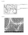
- Fig. 2A is a view schematically showing an example of a structure of the open-cell urethane foam 4 shown in Fig. 1A .
- the open-cell urethane foam 4 has a core layer 4c, and a skin layer 4d that covers the outer circumference of the core layer 4c.
- the core layer 4c includes a larger number of cells 47 as compared to the skin layer 4d ( Figs. 2B and 2C ), and therefore has a density lower than that of the skin layer 4d.
- the core layer 4c is situated at the central part of the open-cell urethane foam 4.
- the skin layer 4d is formed in the vicinity of the inner surfaces of the outer casing 2 and the inner casing 3.
- Fig. 2B is an enlarged photograph showing a state between a pair of cells 47 in the open-cell urethane foam 4 shown in Fig. 2A .
- Fig. 2C is a view for explaining a configuration between a pair of cells 47 shown in Fig. 2B .
- the core layer 4c and the skin layer 4d shown in Fig. 2A include a plurality of cells 47, cell film portions 42 and cell skeleton portions 43 as shown in Figs. 2B and 2C , respectively.
- the ratio of cell film portions 42 is greater in core layer 4c than in the skin layer 4d.
- the ratio of cell skeleton portions 43 is greater in the skin layer 4d, in which foaming is less sufficient, than in the core layer 4c.
- the ratio of cell skeleton portions 43 to cell film portions 42 is higher in the skin layer 4d than in the core layer 4c.
- the cell 47 is a fine cell of, for example, less than 1000 ⁇ m as shown in Figs. 2B and 2C .
- Cells 47 communicate with one another through the later-described first through-hole 44 and second through-hole 45, and therefore cells 47 are continuous.
- the length of the heat transfer route in the open-cell urethane foam 4 increases to improve the heat-insulating properties of the open-cell urethane foam 4 as long as the density of the open-cell urethane foam 4 is fixed.
- the fluid resistance (exhaust resistance) at the time of decompressing the internal space of cells 47 etc. in the open-cell urethane foam 4 increases, leading to an increase in power and time for exhausting air. Accordingly, a size of the cell 47 is determined in consideration of the heat-insulating properties and exhaust efficiency of the open-cell urethane foam 4.
- the cell film portion 42 is formed at a location where cells 47 are closely adjacent to one another, and formed in a film shape between a pair of cells 47 facing each other.
- the thickness of the cell film portion 42 is, for example, as small as about 3 ⁇ m as typically shown in the right upper part and the left lower part of Figs. 2B and 2C .
- the cell skeleton portion 43 is formed at a location where cells 47 are adjacent to one another as typically shown in the central part of Figs. 2B and 2C .
- the thickness of the cell skeleton portion 43 (distance between a pair of cells 47) is larger than that of the cell film portion 42, and is, for example, as large as about 150 ⁇ m ( Figs. 2F and 2G ).
- cell skeleton portion 43 is formed among a plurality of cells 47 facing one another.
- the cell film portion 42 between a pair of cells 47 and the cell film portion 42 between another pair of cells 47 are continuous at the cell skeleton portion 43.
- the open-cell urethane foam 4 may include a region where foaming is insufficient. Such a region may have a state in which cells 47 are dispersed in a bulk resin.
- the first through-hole extends through the cell film portion 42, and the second through-hole extends through the cell skeleton portion 43. Consequently, in the open-cell urethane foam 4, all cells 47 communicate with one another. All cells 47 are not necessarily exactly all the cells 47 existing in the open-cell urethane foam 4. A very small number of cells 47 that do not communicate with one another may remain due to variations in state of foaming, etc. as described above.
- Fig. 2D is an enlarged photograph showing a state of the first through-hole 44 in the cell film portion 42 in Fig. 2B .
- Fig. 2E is a view for explaining a configuration of the cell film portion 42 and first through-hole 44 shown in Fig. 2D .
- the first through-hole 44 extends through the cell film portion 42 as shown in Figs. 2D and 2E .
- Figs. 2D and 2E show a surface of the cell film portion 42 (interface between the cell 47 and the cell film portion 42) as seen from the inside of the cell 47.
- the first through-hole 44 causes mutually closely adjacent cells 47 to communicate with one another.
- the first through-hole 44 is formed as distortion occurs at a molecular level as a result of performing foaming by using a plurality of polyols having different compositions as described later.
- Fig. 2F is an enlarged photograph showing a state of the cell skeleton portion 43 in Fig. 2B .
- Fig. 2G is a view for explaining a configuration of the cell skeleton portion 43 shown in Fig. 2F .
- Fig. 2H is an enlarged photograph showing further in detail a state of the cell skeleton portion 43 shown in Fig. 2F .
- Fig. 2I is a view for explaining a configuration of the cell skeleton portion 43 shown in Fig. 2H .
- the second through-hole 45 is formed at an interface between a powder 46 and a urethane resin (open-cell resin) that forms the open-cell urethane foam 4.
- the second through-hole 45 extends through the cell skeleton portion 43 to cause mutually separately adjacent cells 47 to communicate with one another.
- the diameter size and length size of the second through-hole 45 are greater than the diameter size and length size of the first through-hole 44.
- the second through-hole 45 is formed as the incompatible powder 46 is not adhered to the urethane resin.
- the raw material of the open-cell urethane foam 4 is one obtained by mixing thermosetting urethane resin components (first resin component and second resin component), a foaming agent and the powder 46.
- the first resin component is, for example, a mixture of a plurality of polyols (three polyols in this embodiment), and these polyols have different compositions.
- the second resin component is a polyisocyanate, and for example, a polymethylene polyphenyl polyisocyanate is used as the isocyanate.
- water is used for the foaming agent.
- the powder 46 is a fine powder that is dispersed in the open-cell urethane foam 4.
- the particle size of the powder 46 is smaller than the size of the cell 47, for example less than 1000 ⁇ m, particularly preferably, for example 10 to 30 ⁇ m.
- the powder 46 is incompatible with the resin of the open-cell urethane foam 4, and has a SP value of, for example, 9.5 or less.
- a polyethylene (PE), nylon (Ny-12) or the like is used for the powder 46.
- the SP value of the urethane resin (resin of open-cell urethane foam 4) is, for example, 10 to 11.
- the urethane resin and the powder 46 are harder to be adhered to each other as the difference between the SP value of the urethane resin and the SP value of the powder 46 becomes greater.
- the second through-hole 45 is formed between the urethane resin and the powder 46.
- Additives such as a foam stabilizer, a catalyst, a flame retardant, an antioxidant, a colorant and a viscosity-reducing agent may be added to the urethane liquid as necessary.
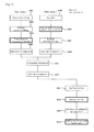
- Fig. 3 is a flow chart showing an example of construction of the refrigerator 20 shown in Fig. 1A .
- the inner casing 3 and the outer casing 2 are independently prepared for the heat-insulating box (heat-insulating housing) 21 of the refrigerator 20.
- a hard resin such as an ABS resin is molded into a sheet (step: S301).
- This hard resin sheet is vacuum-molded into the inner casing 3 having a desired box shape (step: S302). Specifically, hard resin sheet is heated, and the sheet is pressed against a mold of the inner casing 3 before the softened sheet is cooled and solidified. Air is released from a hole of the mold to bring the inside of the mold into a vacuum state, so that the sheet is caused to come into close contact with the mold. Consequently, a desired box shape as the inner casing 3 is obtained.
- step: S303 the back plate of the box-shaped inner casing 3 is punched by a trimming punch to form the air hole 6 at each location where the air hole 6 is to be disposed as shown in Fig. 1A (step: S303).
- a metallic steel plate is provided (step: S305).
- the steel plate is punched by a trimming punch to form the urethane liquid injection port 5 at each location where the urethane liquid injection port 5 is to be disposed as shown in Fig. 1A (step: S306).
- the steel plate after punching is subjected to press molding such as bending to mold the steel plate into a desired box shape as the outer casing 2 (step: S307).
- Predetermined components for the refrigerator 20, which should be attached to the outer casing 2 before the inner casing 3 and the outer casing 2 are combined, are attached to the outer casing 2 (step: S308).
- the inner casing 3 and the outer casing 2 prepared as described above are combined to form a wall body (step: S309). Specifically, a flange formed at the front part of the side surface of the inner casing 3 is fitted in a groove portion formed at the front part of the side surface of the outer casing 2. Consequently, the inner casing 3 is mounted in the outer casing 2 to form a hollow wall body, and this internal space is formed as a heat-insulating space 10.
- Predetermined components for the refrigerator 20, which should be attached before the heat-insulating space 10 is filled with the open-cell urethane foam 4, are attached to wall bodies 2 and 3 (step: S310).
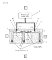
- Fig. 4 is a sectional view for explaining integral foaming/molding of the heat-insulating box 21 using a urethane foaming tool 41a.
- Two urethane liquid injection ports 5 in Fig. 4 represent two urethane liquid injection ports 5 at upper and lower locations on the right side as shown in Fig. 1A .
- the two urethane liquid injection ports 5 are situated at the rear side from each of urethane liquid reservoir portions 4b at three locations.
- a urethane liquid is injected similarly to the urethane liquid injection ports 5 on the right side.
- the urethane foaming tool 41a is a tool for supporting wall bodies 2 and 3 during integral foaming/molding, and includes, for example, a first tool 41a1 and a second tool 41a2.
- the first tool 41a1 is provided with a depression so as to support the wall body on the outer casing 2 side.
- the depression has a shape conforming to the rear surface of the outer casing 2, i.e. a shape corresponding to the rear surface of the heat-insulating box 21.
- the first tool 41a1 is provided with a perforation 41a3 at a position which corresponds to the urethane liquid injection port 5 of the outer casing 2 when the box is fitted in the depression.
- the second tool 41 a2 is provided with a depression so as to support the wall body on the inner casing 3 side.
- the depression has a shape conforming to the front surface of the inner casing 3, i.e. a shape corresponding to the front surface of the heat-insulating box 21 including the partition plate 25.
- the second tool 41a2 is provided with a perforation (not illustrated) at a position which corresponds to the air hole 6 of the inner casing 3 when the box is fitted in the depression. Consequently, the heat-insulating space 10 can communicate with the outside through the air hole 6 and the perforation even when wall bodies 2 and 3 are covered with the urethane foaming tool 41a.
- the urethane foaming tool 41a When the urethane foaming tool 41a is used to perform integral foaming/molding, first the wall body is covered with the first tool 41a1 such that the inner casing 3 side of the wall body is fitted in the depression of the second tool 41 a2 and the outer casing 2 side of the wall body is fitted in the depression of the first tool 41a1. Consequently, the entire surface of the wall body is supported by the urethane foaming tool 41a, so that the wall body can be prevented from being deformed at the time of filling and foaming of the urethane liquid.
- the urethane liquid injection port 5 communicates with the perforation 41a3, and the air hole 6 communicates with the perforation of the second tool 41a2.
- the tip of a liquid feeding hose 41 of a urethane liquid feeding device 40 is connected to the urethane liquid injection port 5 through the perforation 41a3.
- the urethane liquid is injected to each of the urethane liquid injection ports 5 at two locations from the urethane liquid feeding device 40 through the liquid feeding hose 41.
- the amounts of urethane liquids that fed to the urethane liquid injection ports 5 at two locations may be the same, or may be individually adjusted so that the heat-insulating space 10 is filled with the urethane liquid uniformly.
- the urethane liquid flows into the heat-insulating space 10 from each of the urethane liquid injection ports 5 at two locations, flows into urethane liquid reservoir portions 4b at three locations on the front side from the urethane liquid injection ports 5, and is stored in the urethane liquid reservoir portions 4b.
- the components of the urethane liquid are mixed, and a polyol mixture as the first resin component and a polyisocyanate as the second resin component undergo a polymerization reaction to form a thermosetting urethane resin.
- the foaming agent is vaporized by heat generated in the polymerization reaction, so that cells 47 are formed in the urethane resin.
- a plurality of polyols having different compositions cause distortion at a molecular level, so that the first through-hole 44 is formed in the cell film portion 42 as shown in Figs. 2D and 2E . Further, as shown in Figs. 2H and 2I , the second through-hole 45 is formed between the thermosetting urethane resin and the powder 46, and the second through-hole 45 extends through the cell skeleton portion 43. In this manner, the open-cell urethane foam 4 is formed.
- the open-cell urethane foam 4 expands from each urethane liquid reservoir portion 4b toward the urethane liquid injection port 5 while thrusting aside air existing in the heat-insulating space 10, and is formed into a solid phase.
- the open-cell urethane foam 4 moves toward the rear side from each of the urethane liquid reservoir portions 4b at three locations, merges at the urethane foaming/merging portion 4a, and fills the heat-insulating space 10 uniformly.
- the thrust air merges at the urethane foaming/merging portion 4a, and is exhausted from the urethane foaming/merging portion 4a through the air hole 6 ( Fig. 1A ).
- a molded article with the heat-insulating space 10 filled with the open-cell urethane foam 4 is taken out from the urethane foaming tool 41a, and each air hole 6 present in the inner casing 3 of the wall body is sealed as shown in Fig. 3 (step S312).
- Remaining components for the refrigerator 20 are attached to wall bodies 2 and 3 in the refrigerator 20 (step S313).
- Each urethane liquid injection port 5 in the outer casing 2 of the wall body is sealed (step S314). In this way, the refrigerator 20 is produced.
- Timing at which the inner casing 3 and the outer casing 2 are fixed is not particularly limited.
- the inner casing 3 and the outer casing 2 may be fixed by a sticking member, an adhesive or the like at the time of combining the inner casing 3 and the outer casing 2 (step: S309).
- the inner casing 3 and the outer casing 2 may be fixed at the time of sealing the urethane liquid injection port 5 (step S314).
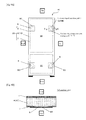
- Fig. 5A is a view showing a method 1 for sealing the air hole 6 of the refrigerator 20.
- Fig. 5B is a local sectional view showing a part of the refrigerator 20 taken along line B-B in Fig. 5A .
- an adhesive such as an epoxy resin is applied individually on a one-to-one basis to the circumferences of air holes 6 at 40 locations in the inner casing 3.
- a disc-shaped air hole sealing material 60 formed of an air impermeable material such as silicone rubber or isobutylene-isoprene rubber is bonded onto each air hole 6 to seal each air hole 6.
- air holes 6 are individually covered with the air hole sealing material 60 as described above, the air hole sealing material 60 is prevented from covering regions other than air holes 6 in the inner casing 3. Thus, the area of the air hole sealing material 60 is small, so that costs can be reduced. Even if some of air holes 6 are not sufficiently sealed, this does not affect the sealing of other air holes 6. Accordingly, deterioration of the sealing property can be suppressed.
- Fig. 6A is a view showing a method 2 for sealing the air hole 6 of the refrigerator 20.
- Fig. 6B is a local sectional view showing a part of the refrigerator 20 taken along line C-C in Fig. 6A .
- an air hole sealing material 61 (sealing material) is bonded collectively to air holes 6 at 30 locations on the refrigerator compartment 26 side in the inner casing 3 to seal these air holes 6.
- Another air hole sealing material 61 is bonded collectively to air holes 6 at 10 locations on the freezer compartment 27 side in the inner casing 3 to seal these air holes 6.
- These two air hole sealing materials 61 are each in the form of a sheet, and formed of an air impermeable material such as silicone rubber or isobutylene-isoprene rubber.
- Fig. 7A is a view showing a method 3 for sealing the air hole 6 of the refrigerator 20.
- Fig. 7B is a local sectional view showing a part of the refrigerator 20 taken along line D-D in Fig. 7A .
- an air hole sealing material 62 (sealing material) is mechanically embedded individually on a one-to-one basis in air holes 6 at 40 locations in the inner casing 3 to seal the air holes 6.
- the air hole sealing material 62 is in the form of a screw (including a bolt), and has a cylinder portion and a head portion.
- the cylinder portion is almost identical in diameter size and length size to the air hole 6, and is fitted in the air hole 6.
- the head portion is in the form of a disc, and its diameter size is larger than the size of the air hole 6.
- the air hole sealing material 62 Since air holes 6 are individually covered with the air hole sealing material 62 as described above, the air hole sealing material 62 is prevented from covering regions other than air holes 6 in the inner casing 3. Thus, the size of the air hole sealing material 62 is small, so that costs can be reduced. Even if some of air holes 6 are not sufficiently sealed, this does not affect the sealing of other air holes 6. Accordingly, deterioration of the sealing property can be suppressed. Since the air hole sealing material 62 is mechanically embedded in the air hole 6, waiting time for hardening the resin after bonding is not required, and remaining components for the refrigerator 20 can be quickly attached after air holes 6 are sealed.
- Fig. 8A is a view showing a method 1 for sealing the urethane liquid injection port 5 of the refrigerator 20.
- Fig. 8B is a local sectional view showing a part of the refrigerator 20 taken along line E-E in Fig. 8A .
- a urethane liquid injection port sealing material 50 (sealing material) is bonded individually on a one-to-one basis to urethane liquid injection ports 5 at four locations using an adhesive or the like.
- the urethane liquid injection port sealing material 50 is in the form of a sheet, and formed of an air impermeable material such as silicone rubber, isobutylene-isoprene rubber or an iron plate. By sealing the urethane liquid injection ports 5 as described above, the area of the urethane liquid injection port sealing material 50 is kept small, so that costs can be reduced.
- Fig. 9A is a view showing a method 2 for sealing the urethane liquid injection port 5 of the refrigerator 20.
- Fig. 9B is a local sectional view showing a part of the refrigerator 20 taken along line F-F in Fig. 9A .
- urethane liquid injection ports 5 at four locations are covered and sealed with a urethane liquid injection port sealing material 51 (sealing material) individually on a one-to-one basis.
- the urethane liquid injection port sealing material 51 is in the form of, for example, a disc, and formed of an air impermeable material such as silicone rubber, isobutylene-isoprene rubber or an iron plate.
- first fixation holes are made at four locations on the outer circumference side of the urethane liquid injection port sealing material 51.
- second fixation holes are made at four locations on the outer circumference of the urethane liquid injection port 5.
- the urethane liquid injection port sealing material 51 is disposed on the urethane liquid injection port 5 such that the first fixation hole and the second fixation hole correspond to each other.
- a fixation member 52 such as a vis is inserted in the first fixation hole and the second fixation hole to fix the urethane liquid injection port sealing material 51 to the outer casing 2. Consequently, the liquid injection port sealing material 51 can cover and seal the urethane liquid injection port 5.
- the fixation member 52 By using the fixation member 52 as described above, the urethane liquid injection port sealing material 51 can be firmly fixed to the outer casing 2 easily and reliably, so that reliability of sealing is improved.
- air holes 6 for releasing air are provided on wall bodies 2 and 3, and resultantly fluidity of the urethane liquid and air is secured during injection and foaming of the urethane liquid in the heat-insulating space 10, so that generation of an air reservoir in the heat-insulating space 10 is suppressed. Consequently, degradation of the open-cell urethane foam 4 by moisture contained in air of the air reservoir is prevented, so that deformation and deterioration of heat-insulating properties of the heat-insulating box 21 can be prevented. Moreover, the heat-insulating space 10 is uniformly filled with the open-cell urethane foam 4, and therefore the heat-insulating properties of the heat-insulating box 21 can be improved.
- urethane liquid injection ports 5 are sealed with urethane liquid injection port sealing materials 50, 51 and 55, and air holes 6 are sealed with air hole sealing materials 60, 61 and 62.
- the heat-insulating space 10 filled with the open-cell urethane foam 4 is airtightly closed, so that air and moisture contained therein are prevented from entering the heat-insulating space 10. Accordingly, degradation of the open-cell urethane foam 4 by moisture is prevented, so that deformation of the external appearance of the heat-insulating box 21 is prevented, and heat-insulating performance of the heat-insulating box 21 is kept high over a long period of time.
- the open-cell urethane foam 4 is molded by integral foaming in the airtightly closed heat-insulating space 10 as in the conventional technique, generation of a skin layer 4d having a high density and having a large number of closed cells cannot be avoided. It is neither disclosed nor suggested in the conventional technique that cells in the skin layer 4d are made to communicate with one another. On the other hand, by using a plurality of polyols of different compositions and a urethane liquid containing the powder 46, cells 47 can be made to communicate with one another throughout the open-cell urethane foam 4 including the skin layer 4d.
- the first through-hole 44 extending through the cell film portion 42 can be formed using a plurality of polyols of different compositions, and the second through-hole 45 extending through the cell skeleton portion 43 can be formed using the powder 46.
- the powder 46 having a diameter size larger than the thickness size of the cell skeleton portion 43 the second through-hole 45 can be formed not only in the core layer 4c but also in the skin layer 4d having a large number of cell skeleton portions 43.
- cells 47 communicate with one another through the through-holes 44 and 45 throughout the open-cell urethane foam 4.
- the open-cell urethane foam 4 has no or almost no closed cells, and therefore deformation of the airtightly closed heat-insulating box 21 and deterioration of the heat-insulating properties of the heat-insulating box 21 by a residual gas released from closed cells can be prevented.
- the diameter size of the air hole 6 smaller than the size of the urethane liquid injection port 5
- generation of an air reservoir can be suppressed while leakage of the urethane liquid is suppressed.
- a heat-insulating box 21 according to Embodiment 2 of the present invention is formed by evacuating a heat-insulating space 10 after filling the heat-insulating space 10 with an open-cell urethane foam 4 shown in Fig. 1A . Consequently, the pressure of the heat-insulating space 10 is lower than atmospheric pressure, so that the heat-insulating space 10 is in a vacuum state.
- the vacuum state includes a state in which the pressure of the heat-insulating space 10 is lower than atmospheric pressure.
- the urethane liquid injection port 5 in Embodiment 1 is used also as an exhaust hole (gas circulation port) to which a vacuum pump for evacuation is connected. Therefore, the example of a structure of the heat-insulating box 21 shown in Figs. 1A and 1B can be applied to the heat-insulating box 21 according to Embodiment 2.
- Fig. 10 is a flow chart of construction of a refrigerator 20 including the heat-insulating box 21 according to Embodiment 2.
- a hard resin such as an ABS resin and a metal foil are provided as shown in Fig. 10 (step: S1001).
- Insert molding for integrating the metal foil and the hard resin is performed in the process of injecting the hard resin into a predetermined mold and solidifying the hard resin (step S1002). Consequently, the box-shaped inner casing 3 with desired airtightness is obtained.
- the back plate of the inner casing 3 is punched by a trimming punch to form air holes 6 at each of predetermined locations where the air hole 6 is to be disposed (step: S1003).
- Predetermined components for the refrigerator 20, which should be attached before the inner casing 3 and the outer casing 2 are combined, are attached to the inner casing 3 (step: S1004).
- a metallic steel plate may be used for the inner casing 3 similarly to molding of an outer casing 2 described below for maintaining the airtightness of a refrigerator 20.
- the metallic steel plate is punched by a trimming punch to form a urethane liquid injection port 5 at each of locations where the urethane liquid injection port 5 is to be disposed (steps: S1005 and S1006).
- the steel plate after punching is subjected to press molding such as bending (step: S1007). Consequently, a desired box shape as the outer casing 2 is obtained.
- Predetermined components for the refrigerator 20, which should be attached before the inner casing 3 and the outer casing 2 are combined, are attached to the outer casing 2 (step: S1008).
- step: S1009 The inner casing 3 and the outer casing 2 independently prepared as described above are combined (attached together) (step: S1009).
- the specific attachment method is similar to that in Embodiment 1, and therefore descriptions thereof are omitted.
- Predetermined components for the refrigerator 20, which should be attached before the heat-insulating space 10 is filled with the open-cell urethane foam 4, are attached to wall bodies 2 and 3 (step: S1010).
- the open-cell urethane foam 4 is subjected to integral foaming/molding in the heat-insulating space 10 between the outer casing 2 and the inner casing 3 (step: S1011).
- the integral foaming/molding is as described above with reference to Fig. 4 . Consequently, air merged into a urethane liquid reservoir 4b is exhausted from the air hole 6 on the back surface of the inner casing 3 (see Fig. 1A ), so that generation of an air reservoir (urethane-unfilled portion) is suppressed in the heat-insulating space 10 of the heat-insulating box 21.
- step S1012 air holes 6 at 40 locations in the inner casing 3 are sealed (step S1012).
- a vacuum pump is connected to the urethane liquid injection port 5 used also as an exhaust hole, and the heat-insulating space 10 filled with the open-cell urethane foam 4 is evacuated.
- the heat-insulating space 10 is hereby decompressed, remaining components for the refrigerator 20 are attached to wall bodies 2 and 3 (step S1013).
- the urethane liquid injection port 5 used also as an exhaust hole is sealed (step S1014).
- the method for sealing the urethane liquid injection port 5 used also as an exhaust hole is similar to that in Embodiment 1, and urethane injection port sealing materials 50 and 51 can be used.
- sealing methods shown in Figs. 11A and 11B can also be employed.
- Fig. 11A is a view showing a method for sealing the urethane liquid injection port 5 also used as an exhaust hole.
- Fig. 11B is a local sectional view showing a part of the refrigerator 20 taken along line G-G in Fig. 11A .
- urethane liquid injection ports 5 at four locations are sealed with a urethane liquid injection port sealing material 55 (sealing material) individually on a one-to-one basis.
- the urethane liquid injection port sealing material 55 is formed of an air impermeable material such as silicone rubber, isobutylene-isoprene rubber or an iron plate, and has a flat portion 56, a pinch portion 57 and an exhaust hole 58.
- the flat portion 56 is in the form of a circle having a diameter larger than the hole size of the urethane liquid injection port 5 used also as an exhaust hole, and is disposed on the urethane liquid injection port 5.
- the exhaust hole 58 is disposed at the central part of the flat portion 56, and has a hole size equal to or smaller than the hole size of the urethane liquid injection port 5.
- the pinch portion 57 is cylindrically erected from the exhaust hole 58, and can be sealed at its tip.
- the hole size of the exhaust hole 58 is determined so that shortening of time required for evacuation and ease of pinching can be realized in a well-balanced manner. For example, when the hole size of the exhaust hole 58 is small, time required for evacuation increases, but sealing by the pinch portion 57 becomes easier. On the other hand, when the hole size of the exhaust hole 58 is large, sealing by the pinch portion 57 becomes less easy, but time required for evacuation can be shortened. In this embodiment, a hole size of, for example, 10 mm can be employed. When the hole size of the exhaust hole 58 is small, the exhaust hole 58 is not necessarily sealed by the pinch portion 57, but may be sealed using a sealing material such as, for example, a resin or glass.
- the heat-insulating properties of the heat-insulating box 21 with the heat-insulating space 10 filled with the open-cell urethane foam 4 can be kept high by sealing the exhaust hole 58.
- the exhaust hole 58 can be sealed in parallel to sealing the urethane liquid injection port 5. Consequently, the man-hour for constructing the heat-insulating box 21 and cooling/warming equipment (e.g. refrigerator) including the heat-insulating box 21 can be reduced.
- cooling/warming equipment e.g. refrigerator
- An exhaust hole may be disposed independently of the urethane liquid injection port 5 rather than using the urethane liquid injection port 5 also as an exhaust hole.
- the method for sealing the urethane liquid injection port 5 in Embodiment 1 can be applied as the method for sealing the exhaust hole in this case.
- a gas adsorbing device 85 that adsorbs a carbon dioxide gas etc. in an open-cell urethane foam 4 is disposed in a heat-insulating space 10 as shown in Fig. 12.
- Fig. 12 is a front view of a refrigerator 20 including a heat-insulating box 21 according to Embodiment 3 of the present invention.
- One gas adsorbing device 85 is disposed in the heat-insulating space 10 on each of both side surfaces of a freezer compartment 27 on the lower left side and the lower right side of the heat-insulating box 21 shown in Fig. 12 . Consequently, since the cooling retention temperature of the freezer compartment 27 is lower than that of a refrigerator compartment 26, a gas in the heat-insulating space 10 moves into the heat-insulating space on the circumference of the freezer compartment 27, so that the gas can be efficiently adsorbed by the gas adsorbing device 85.
- the disposition and number of gas adsorbing devices 85 can be changed according to a size and form of the refrigerator 20, and the number and disposition thereof is not limited to the two locations described above.
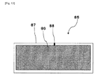
- Fig. 13 is one example of a sectional view of the gas adsorbing device 85.
- the gas adsorbing device 85 includes a gas adsorption substance 86, and a storage container 87 having an opening 88 for storing the gas adsorbing material 86.
- the gas adsorption substance 86 plays the role of adsorbing gases such as water vapor, air and a carbon dioxide gas which remain in the closed space or enter the closed space.
- gases such as water vapor, air and a carbon dioxide gas which remain in the closed space or enter the closed space.
- the gas adsorbing material 86 that can be used include, but are not particularly limited to, chemical adsorption substances such calcium oxide and magnesium oxide, physical adsorption substances such as zeolite, and mixtures thereof.
- a copper-ion-exchanged ZSM-5 type zeolite having both chemical adsorptivity and physical adsorptivity can also be used as the gas adsorbing material 86.
- the copper-ion-exchanged ZSM-5 type zeolite has a particularly high nitrogen adsorbing capability at a pressure lower than atmospheric pressure, and therefore can strongly adsorb nitrogen at the time of ingress of air.
- an adsorbent that adsorbs a carbon dioxide gas for example a ZSM-5 zeolite ion-exchanged with barium and/or strontium, can also be used as the gas adsorbing material 86.
- the gas adsorbing material 86 that adsorbs a carbon dioxide gas is desired to be a material obtained by ion-exchanging a ZSM-5 type zeolite as a main agent with barium and/or strontium.
- the carbon dioxide gas adsorption amount of a Na-A type zeolite, which is a part of the conventional technique, is 3 cc/g at a pressure of 10 Pa.
- the carbon dioxide gas adsorption amount of the barium-ion-exchanged ZSM-5 type zeolite is 12 cc/g at a pressure of 10 Pa, so that a large volume of lean carbon dioxide gas can be adsorbed and removed. Consequently, the vacuum degree of the heat-insulating space 10 in which the gas adsorbing device 85 is disposed can be kept high.
- the zeolite ion-exchanged with barium and/or strontium as described above is a carbon dioxide adsorption material that includes a ZSM-5 type zeolite containing barium (Ba) and/or strontium (Sr), with the ZSM-5 type zeolite including a Ba-O-Ba species and/or a Sr-O-Sr species. Accordingly, a strong interaction with carbon dioxide is produced, and therefore even under a condition of lean carbon dioxide with the equilibrium pressure being lower than atmospheric pressure, carbon dioxide is strongly adsorbed, so that a large volume of carbon dioxide can be adsorbed.
- One example of methods for checking whether the Ba-O-Ba species is contained or not is a method in which FT-IR measurement is performed using adsorbed acetylene as a probe.
- the storage container 87 is hardly permeable to gases such as air and water vapor, and plays the role of preventing the gas adsorbing material 86 from coming into contact with a gas before the gas adsorbing device 85 is used.
- the material and shape of the storage container 87 are not particularly specified.
- a metal material such as, for example, aluminum, copper, iron or stainless steel is used.
- the storage container 87 is molded in a shape of, for example, a narrow and long and flat cylinder.
- the example of construction of the refrigerator 20 according to Embodiment 3 is almost the same as the example of construction of the refrigerator 20 shown in the flow chart of Fig. 10 .
- a plurality of gas adsorbing devices 85 are dispersively disposed in the heat-insulating space 10 in wall bodies 2 and 3 at the time of attaching components to wall bodies 2 and 3 by the treatment in step S1010 shown in Fig. 10 .
- a urethane liquid of an open-cell urethane foam 4 is injected into the heat-insulating space 10 from the urethane liquid injection port 5 used also as an exhaust hole.
- air holes 6 are sealed with air hole sealing materials 60, 61 and 65 etc.
- the heat-insulating space 10 is then evacuated from a urethane liquid injection port 5 used also as an exhaust hole to seal the urethane liquid injection port 5 used also as an exhaust hole with urethane liquid injection port seaming materials 50, 51 and 55 etc.
- the time for bringing the heat-insulating space 10 into vacuum can be shortened. That is, at the time of evacuation, air can be sufficiently exhausted by a vacuum pump at a pressure of viscous flow (low vacuum), but in the high vacuum degree range of molecular flow (high vacuum), the exhaust resistance increases, and therefore it takes much time to exhaust air by a vacuum pump.
- gas adsorbing devices 85 are dispersively disposed in the heat-insulating space 10 beforehand to cause the gas adsorbing devices 85 to exhibit a gas adsorption function. Consequently, the exhaust distance of the open-cell urethane foam 4 is reduced, so that the heat-insulating space 10 can be efficiently decompressed (evacuated).
- the gas adsorbing device 85 adsorbs a very small amount of gas remaining after the heat-insulating space 10 of the heat-insulating box 21 is evacuated, and therefore the heat-insulating space 10 can be kept at a desired vacuum degree.
- a very small amount of gas remaining in the heat-insulating space 10 includes, in addition to air components, a carbon dioxide gas produced by a reaction of water with an isocyanate.
- gas adsorbing devices 85 for adsorbing air gas adsorbing devices 85 for adsorbing a carbon dioxide gas may be dispersively disposed in the heat-insulating space 10.
- Gas adsorbing devices 86 may be dispersively disposed in the heat-insulating space 10 of the heat-insulating box 21 and the heat-insulating wall according to Embodiment 1 in which evacuation is not performed. When the gas adsorption function of the gas adsorbing device is exhibited, degradation of the open-cell urethane foam 4 in the heat-insulating space 10 is further easily prevented.
- a heat-insulating box 21 according to Embodiment 4 of the present invention is formed by molding an open-cell urethane foam 4 by integral foaming with one of wall bodies as a skin material, and mounting the other wall body on the resulting molded body. While this embodiment is described with one of wall bodies being an inner casing 3 and the other wall body being an outer casing 2, a case where they are interchanged does not lead to a difference, and therefore descriptions of the case are omitted.
- Fig. 14 is a sectional view for explaining integral foaming/molding of the heat-insulating box 21.
- a urethane foaming tool 41 a shown in Fig. 14 is similar to the urethane foaming tool 41a shown in Fig. 4 except for a first tool 41a1, and descriptions of similar parts are omitted.
- the urethane foaming tool 41a described in this embodiment supports a wall body 3 at the time of integral foaming/molding, and functions as a mold for molding the open-cell urethane foam 4. That is, a second tool 41 a2 supports the inner casing 3 with the inner casing 3 fitted in a depression of the tool.
- the outer casing 2 is not fitted in a depression provided in the first tool 41a1, and the depression has a shape conforming to the front surface of the outer casing 2, and functions as a mold on the rear surface side of the heat-insulating box 21.
- Air thrust aside from a heat-insulating space 10 at the time of injecting and foaming an urethane liquid may be discharged from, for example, a gap between the first tool 41a1 and the second tool 41 a2.
- an air hole 6 of the inner casing 3 and a perforation of the second tool 41 a2, which is disposed in correspondence with the air hole 6, are not required to be provided.
- the urethane foaming tool 41a When the urethane foaming tool 41a is used to perform integral foaming/molding, first the inner casing 3 is fitted in the second tool 41 a2 as shown in Fig. 14 , and the first tool 41a1 is disposed on the second tool 41a2. Consequently, an internal space surrounded by the front surface of the depression of the first tool 41a1 and the rear surface of the inner casing 3 is formed.
- the internal space has a shape identical to that of the heat-insulating space 10 surrounded by the front surface of the outer casing 2 and the rear surface of the inner casing 3.
- a tip of a liquid feeding hose 41 of a urethane liquid feeding device 40 is connected to a urethane liquid injection port 5 to inject a urethane liquid to the urethane liquid injection port 5 from the urethane liquid feeding device 40 through the liquid feeding hose 41. Consequently, the urethane liquid is foamed integrally with the inner casing 3 to form a molded body with the inner casing 3 as a skin material of the open-cell urethane foam 4.
- the open-cell urethane foam 4 has a shape corresponding to the heat-insulating space 10. The front surface of the open-cell urethane foam 4 is covered with the inner casing 3, while the rear surface thereof is exposed.
- the molded body is taken out from the urethane foaming tool 41a, and the rear surface of the open-cell urethane foam 4 is covered with the outer casing 2. Consequently, the whole of the open-cell urethane foam 4 is covered with wall bodies 2 and 3 to produce the heat-insulating box 21 with the wall bodies and the open-cell urethane foam 4 molded integrally.
- the heat-insulating space 10 surrounded by the inner casing 3 and the outer casing 2 may be brought into a vacuum state after the open-cell urethane foam 4 foamed integrally with the inner casing 3 is covered with the outer casing 2.
- an exhaust hole is provided in the inner casing 3 and/or the outer casing 2
- air is exhausted from the exhaust hole to bring the heat-insulating space 10 into a vacuum state, followed by sealing the exhaust hole with an exhaust hole sealing material.
- a gas adsorbing device 85 may be disposed in the heat-insulating space 10 surrounded by the inner casing 3 and the outer casing 2 after the open-cell urethane foam 4 foamed integrally with the inner casing 3 is covered with the outer casing 2.
- the open-cell urethane foam 4 may be foamed integrally with the inner casing 3 and the air adsorbing device 85 to be molded, followed by mounting the outer casing 2 on the resulting molded body.
- the rear surface of the open-cell urethane foam 4 is exposed.
- a skin layer at an area corresponding to the exhaust hole or the urethane liquid injection port 5 used also as an exhaust hole on the rear surface of the open-cell urethane foam 4 can be removed. Consequently, an area where a large number of cells 47 and through-holes 44 and 45 are present in the open-cell urethane foam 4 is exposed. Therefore, when a vacuum pump is connected to this area, air in the open-cell urethane foam 4 can be smoothly discharged by passing through cells 47 and through-holes 44 and 45.
- the inner casing 3 may be provided with the air hole 6.
- a perforation of the second tool 41 a2, which is disposed in correspondence with the air hole 6, is provided. Accordingly, the open-cell urethane foam 4 foamed integrally with the inner casing 3 is covered with the outer casing 2, followed by sealing the air hole 6 with an air hole sealing material.
- the outer casing 2 and the open-cell urethane foam 4 may be integrally foamed to be molded, followed by covering the resulting molded body with the inner casing 3.
- the urethane liquid injection port 5 is provided in the outer casing 2, and a perforation 41a3 is provided at a position in the first tool 41a1 which corresponds to the urethane liquid injection port 5.
- the open-cell urethane foam 4 foamed integrally with the inner casing 2 is covered with the inner casing 3, followed by sealing the urethane liquid injection port 5 with a urethane liquid injection port sealing material to form the heat-insulating box 21.
- the inner casing 3 and the open-cell urethane foam 4 are integrally foamed to be molded, followed by mounting the other box, i.e. the outer casing 2 on the resulting molded body to produce the heat-insulating box 21, so that deformation of the heat-insulating box 21 can be reduced.
- the outer casing 2 is formed of a metal and the inner casing 3 is formed of a resin
- the thermal expansion coefficient of the outer casing 2 is different from the thermal expansion coefficient of each of the inner casing 3 and the open-cell urethane foam 4.
- a change in size of the inner casing 3 and the open-cell urethane foam 4 is greater than a change in size of the outer casing 2. Accordingly, the heat-insulating box 21 formed by combining the outer casing 2 and the inner casing 3, and then filling the heat-insulating space 10 therebetween with the open-cell urethane foam 4 may be deformed. Thus, the outer casing 2 is excluded, and the inner casing 3 and the urethane liquid of the open-cell urethane foam 4 are integrally foamed to be molded.
- the thermal expansion coefficients of the inner casing 3 and the open-cell urethane foam 4 are close to each other, they are thermally expanded to the same degree, and then cooled and contracted, so that the resulting molded body is hard to be deformed.
- the outer casing 2 having a thermal expansion coefficient different from that of the open-cell urethane foam 4 is mounted on the molded body to form the heat-insulating box 21, dimensional deformation of the heat-insulating box 21 can be prevented.
- the heat-insulating box 21 that is a box-shaped container which has an internal space and is opened at the front has been described as one example of the heat-insulating wall.
- the shape etc. of the heat-insulating wall is not limited thereto. That is, the heat-insulating wall should include a wall body which functions as a skin material, and an open-cell resin body of thermosetting resin which is formed integrally with at least a part of the wall body and which functions as a heat-insulating material.
- a heat-insulating space 10 of a substantially flat plate-shaped wall body 23 may be filled with an open-cell urethane foam 4 to form a substantially flat plate-shaped heat-insulating wall.
- the heat-insulating wall is used for, for example, a door of a refrigerator 20 and a door of a house.
- the wall body 23 includes one hollow container, and its internal space is used as a heat-insulating space 10.
- the heat-insulating box 21 is used for a flame of the refrigerator 20, but the use of the heat-insulating box 21 is not limited thereto.
- the heat-insulating box 21 can be used for a pot shown in Fig. 16 , a housing of a portable cooling box, a housing of a thermostatic bath, a housing of a hot water storage tank, a cooler box and the like.
- an outer casing 2 and an inner casing 3 each have a bottomed cylindrical shape, and the inner casing 3 is stored in the outer casing 2.
- the heat-insulating space 10 between the outer casing 2 and the inner casing 3 is filled with the open-cell urethane foam 4 by integral foaming.
- a urethane injection port 5 extending through the outer casing 2 is sealed with a urethane liquid injection port sealing material 50, and an air hole 6 extending through the inner casing 3 is sealed with an air hole sealing material 60.
- the open-cell resin body is the open-cell urethane foam 4, and a thermosetting urethane resin is used as a resin that forms the open-cell resin body.
- the open-cell resin body and the constituent resin thereof are not limited to the open-cell urethane foam and a thermosetting urethane resin as long as the constituent resin is a thermosetting resin.
- the open-cell resin body may be an open-cell phenol foam, and a thermosetting phenol resin may be used as a constituent resin thereof.
- Raw materials of the phenol resin include phenol resin components (e.g. phenol and formaldehyde), a foaming agent and a powder. This powder causes a second through-hole to be formed in a cell skeleton portion of the phenol resin.
- a plurality of polyols having different compositions are used, and by means of distortion resulting therefrom, the first through-hole 44 is formed in the cell film portion 42.
- a foam breaker e.g. calcium stearate
- breaking the cell film portion 42 may be blended in the urethane liquid.
- the heat-insulating box of the present invention is economized in energy by improving heat-insulating performance while increasing the internal volume, and can be used in applications such as those of refrigerators and vending machines, hot-water supply containers, heat-insulating materials for buildings, heat-insulating materials for automobiles and cooling/warming boxes.
Landscapes
- Engineering & Computer Science (AREA)
- Chemical & Material Sciences (AREA)
- General Engineering & Computer Science (AREA)
- Mechanical Engineering (AREA)
- Combustion & Propulsion (AREA)
- Physics & Mathematics (AREA)
- Thermal Sciences (AREA)
- Materials Engineering (AREA)
- General Chemical & Material Sciences (AREA)
- Health & Medical Sciences (AREA)
- Chemical Kinetics & Catalysis (AREA)
- Medicinal Chemistry (AREA)
- Polymers & Plastics (AREA)
- Organic Chemistry (AREA)
- Refrigerator Housings (AREA)
- Thermal Insulation (AREA)
- Polyurethanes Or Polyureas (AREA)
Priority Applications (1)
| Application Number | Priority Date | Filing Date | Title |
|---|---|---|---|
| EP19183478.7A EP3578906A1 (fr) | 2012-06-20 | 2013-06-20 | Paroi d'isolation thermique |
Applications Claiming Priority (3)
| Application Number | Priority Date | Filing Date | Title |
|---|---|---|---|
| JP2012138910 | 2012-06-20 | ||
| JP2012280672A JP5310929B1 (ja) | 2012-06-20 | 2012-12-25 | 断熱壁、断熱箱体及びその製造方法 |
| PCT/JP2013/003873 WO2013190845A1 (fr) | 2012-06-20 | 2013-06-20 | Paroi isolante, boîte isolante et procédé de fabrication pour celles-ci |
Related Child Applications (2)
| Application Number | Title | Priority Date | Filing Date |
|---|---|---|---|
| EP19183478.7A Division EP3578906A1 (fr) | 2012-06-20 | 2013-06-20 | Paroi d'isolation thermique |
| EP19183478.7A Division-Into EP3578906A1 (fr) | 2012-06-20 | 2013-06-20 | Paroi d'isolation thermique |
Publications (3)
| Publication Number | Publication Date |
|---|---|
| EP2865973A1 true EP2865973A1 (fr) | 2015-04-29 |
| EP2865973A4 EP2865973A4 (fr) | 2015-07-01 |
| EP2865973B1 EP2865973B1 (fr) | 2019-08-14 |
Family
ID=49529541
Family Applications (2)
| Application Number | Title | Priority Date | Filing Date |
|---|---|---|---|
| EP19183478.7A Withdrawn EP3578906A1 (fr) | 2012-06-20 | 2013-06-20 | Paroi d'isolation thermique |
| EP13806834.1A Active EP2865973B1 (fr) | 2012-06-20 | 2013-06-20 | Paroi d'isolation thermique, boîte d'isolation thermique et son procédé de production |
Family Applications Before (1)
| Application Number | Title | Priority Date | Filing Date |
|---|---|---|---|
| EP19183478.7A Withdrawn EP3578906A1 (fr) | 2012-06-20 | 2013-06-20 | Paroi d'isolation thermique |
Country Status (5)
| Country | Link |
|---|---|
| US (2) | US20150184789A1 (fr) |
| EP (2) | EP3578906A1 (fr) |
| JP (1) | JP5310929B1 (fr) |
| CN (1) | CN104380020B (fr) |
| WO (1) | WO2013190845A1 (fr) |
Cited By (2)
| Publication number | Priority date | Publication date | Assignee | Title |
|---|---|---|---|---|
| EP3144612A3 (fr) * | 2015-08-26 | 2017-06-14 | Lg Electronics Inc. | Réfrigérateur |
| EP3519746A4 (fr) * | 2016-10-03 | 2020-06-17 | Whirlpool Corporation | Système d'encapsulation pour relier un élément de rupture de pont thermique à un revêtement métallique |
Families Citing this family (17)
| Publication number | Priority date | Publication date | Assignee | Title |
|---|---|---|---|---|
| JP6408329B2 (ja) * | 2014-10-02 | 2018-10-17 | 日立アプライアンス株式会社 | 冷蔵庫の製造方法 |
| JP6408345B2 (ja) * | 2014-11-05 | 2018-10-17 | 日立アプライアンス株式会社 | 冷蔵庫の断熱箱体の製造方法 |
| JP2016196933A (ja) * | 2015-04-06 | 2016-11-24 | パナソニックIpマネジメント株式会社 | 真空断熱体 |
| JP2016200232A (ja) * | 2015-04-13 | 2016-12-01 | パナソニックIpマネジメント株式会社 | 真空断熱体及びそれを用いた断熱容器、断熱壁 |
| US10280673B2 (en) | 2015-06-11 | 2019-05-07 | Lg Electronics Inc. | Refrigerator and control method for refrigerator |
| JP6556564B2 (ja) * | 2015-09-01 | 2019-08-07 | 日立グローバルライフソリューションズ株式会社 | 貯湯タンクユニット |
| CN105261119B (zh) * | 2015-10-28 | 2018-08-24 | 广东东吉智能设备有限公司 | 一种自动售货机彩涂板发泡箱体 |
| CA3044699A1 (fr) * | 2016-12-02 | 2018-06-07 | Polyvalor, Limited Partnership | Mousse acoustique a pores ouverts, procede destine a sa fabrication et ses utilisations |
| CN106766609B (zh) * | 2016-12-29 | 2024-01-12 | 青岛海尔特种电冰柜有限公司 | 组装式内胆组件、制冷设备用箱体及制冷设备 |
| JP6875221B2 (ja) * | 2017-07-25 | 2021-05-19 | 日立グローバルライフソリューションズ株式会社 | 冷蔵庫 |
| CN111148955B (zh) | 2017-10-05 | 2021-10-22 | 惠而浦公司 | 用于结合在器具内的隔热结构的填充端口 |
| CN112109265A (zh) * | 2019-06-20 | 2020-12-22 | 海尔智家股份有限公司 | 冰箱发泡密封机构 |
| CN111735265B (zh) * | 2020-06-22 | 2021-12-21 | 长虹美菱股份有限公司 | 一种防发泡收缩变形的冰箱门体 |
| CN111823473A (zh) * | 2020-07-17 | 2020-10-27 | 山东朗丽新材料有限公司 | 一种乳胶海绵制品模具及使用方法 |
| CN114102957A (zh) * | 2020-08-31 | 2022-03-01 | 青岛海尔特种制冷电器有限公司 | 箱体、箱体的制备方法及冰箱 |
| KR20220030127A (ko) * | 2020-09-02 | 2022-03-10 | 코웨이 주식회사 | 단열구조 일체형 탱크 |
| CN114413558B (zh) * | 2021-12-14 | 2025-01-10 | 青岛海尔电冰箱有限公司 | 发泡塑型件及具有其的冰箱 |
Family Cites Families (23)
| Publication number | Priority date | Publication date | Assignee | Title |
|---|---|---|---|---|
| JPS54128856A (en) * | 1978-03-29 | 1979-10-05 | Hitachi Ltd | Manufacturing process of heat-insulating box |
| JPS61235671A (ja) * | 1985-04-10 | 1986-10-20 | 松下冷機株式会社 | 断熱体 |
| JPH02192580A (ja) * | 1989-01-20 | 1990-07-30 | Matsushita Refrig Co Ltd | 断熱箱体の製造方法 |
| JPH04143586A (ja) * | 1990-10-04 | 1992-05-18 | Matsushita Refrig Co Ltd | 断熱体 |
| TW293022B (fr) * | 1992-07-27 | 1996-12-11 | Takeda Pharm Industry Co Ltd | |
| JPH06213561A (ja) * | 1993-01-18 | 1994-08-02 | Hitachi Ltd | 断熱材及びそれを用いた冷蔵庫 |
| DE4325879C3 (de) * | 1993-08-02 | 1999-05-20 | Depron Bv | Folie aus einem thermoplastischen Kunststoffschaum, Verfahren zu ihrer Herstellung sowie ihre Verwendung |
| JP3113471B2 (ja) * | 1993-11-24 | 2000-11-27 | 三洋電機株式会社 | 冷蔵庫 |
| JPH07167551A (ja) * | 1993-12-15 | 1995-07-04 | Hitachi Ltd | 断熱箱体 |
| KR0184681B1 (ko) * | 1995-01-24 | 1999-05-15 | 구보타 다다시 | 탄산가스 흡착제를 가지는 발포 단열재와 그 발포 단열재의 제조방법 |
| JPH08311230A (ja) * | 1995-05-18 | 1996-11-26 | Asahi Chem Ind Co Ltd | 微細連続気泡発泡体とその製造方法及びそれを用いた真空断熱材 |
| JP2948764B2 (ja) * | 1996-08-29 | 1999-09-13 | シャープ株式会社 | 断熱箱体および断熱構造の製造方法 |
| JP4097096B2 (ja) * | 1997-11-10 | 2008-06-04 | 三菱電機株式会社 | 断熱体 |
| DE19917787A1 (de) * | 1999-04-20 | 2000-11-02 | Bayer Ag | Komprimierte Polyurethanhartschaumstoffe |
| JP3781598B2 (ja) * | 1999-12-28 | 2006-05-31 | 日清紡績株式会社 | 真空断熱材の変形方法、真空断熱材の固定方法、冷凍・冷蔵容器及び断熱箱体 |
| EP1401731A2 (fr) * | 2000-11-29 | 2004-03-31 | American Aerogel Corporation | Barrieres d'isolation et procedes de fabrication associes |
| US7341776B1 (en) * | 2002-10-03 | 2008-03-11 | Milliren Charles M | Protective foam with skin |
| JP2004177065A (ja) * | 2002-11-29 | 2004-06-24 | Hitachi Home & Life Solutions Inc | 冷蔵庫 |
| US6958365B2 (en) * | 2003-05-13 | 2005-10-25 | Eastman Kodak Company | Manufacturing process for open celled microcellular foam |
| JP4737967B2 (ja) * | 2004-10-13 | 2011-08-03 | 株式会社イノアックコーポレーション | ポリウレタン発泡体及びその製造方法 |
| JP2007238141A (ja) * | 2006-03-09 | 2007-09-20 | Matsushita Electric Ind Co Ltd | 真空容器 |
| EP2035738B1 (fr) * | 2006-06-22 | 2014-05-07 | Basf Se | Éléments d'isolation thermique |
| JP2008101791A (ja) * | 2006-10-17 | 2008-05-01 | Matsushita Electric Ind Co Ltd | 断熱箱体およびその製造方法 |
-
2012
- 2012-12-25 JP JP2012280672A patent/JP5310929B1/ja active Active
-
2013
- 2013-06-20 US US14/409,353 patent/US20150184789A1/en not_active Abandoned
- 2013-06-20 WO PCT/JP2013/003873 patent/WO2013190845A1/fr not_active Ceased
- 2013-06-20 EP EP19183478.7A patent/EP3578906A1/fr not_active Withdrawn
- 2013-06-20 EP EP13806834.1A patent/EP2865973B1/fr active Active
- 2013-06-20 CN CN201380026055.3A patent/CN104380020B/zh active Active
-
2017
- 2017-06-08 US US15/617,693 patent/US20170268715A1/en not_active Abandoned
Cited By (7)
| Publication number | Priority date | Publication date | Assignee | Title |
|---|---|---|---|---|
| EP3144612A3 (fr) * | 2015-08-26 | 2017-06-14 | Lg Electronics Inc. | Réfrigérateur |
| US10386108B2 (en) | 2015-08-26 | 2019-08-20 | Lg Electronics Inc. | Refrigerator having outer case and inner case for distributing cool air |
| US11346592B2 (en) | 2015-08-26 | 2022-05-31 | Lg Electronics Inc. | Refrigerator having outer case and inner case for distributing cool air |
| EP3519746A4 (fr) * | 2016-10-03 | 2020-06-17 | Whirlpool Corporation | Système d'encapsulation pour relier un élément de rupture de pont thermique à un revêtement métallique |
| US11402149B2 (en) | 2016-10-03 | 2022-08-02 | Whirlpool Corporation | Encapsulation system for a thermal bridge breaker-to-metal liner |
| US12055344B2 (en) | 2016-10-03 | 2024-08-06 | Whirlpool Corporation | Encapsulation system for a thermal bridge breaker-to-metal liner |
| US12410970B2 (en) | 2016-10-03 | 2025-09-09 | Whirlpool Corporation | Encapsulation system for a thermal bridge breaker-to-metal liner |
Also Published As
| Publication number | Publication date |
|---|---|
| WO2013190845A1 (fr) | 2013-12-27 |
| JP2014149091A (ja) | 2014-08-21 |
| EP3578906A1 (fr) | 2019-12-11 |
| US20150184789A1 (en) | 2015-07-02 |
| EP2865973A4 (fr) | 2015-07-01 |
| JP5310929B1 (ja) | 2013-10-09 |
| EP2865973B1 (fr) | 2019-08-14 |
| US20170268715A1 (en) | 2017-09-21 |
| CN104380020A (zh) | 2015-02-25 |
| CN104380020B (zh) | 2016-09-07 |
Similar Documents
| Publication | Publication Date | Title |
|---|---|---|
| EP2865973B1 (fr) | Paroi d'isolation thermique, boîte d'isolation thermique et son procédé de production | |
| US10781963B2 (en) | Heat-insulating wall, and heat-insulating housing and method for producing the same | |
| JP2011241988A (ja) | 断熱箱体および冷蔵庫 | |
| JP2011196644A (ja) | 断熱箱体、及び断熱箱体の製造方法、及び冷凍冷蔵庫 | |
| KR19980071646A (ko) | 단열상자체 및 그 제조방법 | |
| WO2017098694A1 (fr) | Isolateur thermique sous vide, son procédé de fabrication et dispositif d'isolation thermique le comportant | |
| JPH11159693A (ja) | 真空断熱パネル及びその製造方法並びにそれを用いた断熱箱体 | |
| CN107108102A (zh) | 真空容器 | |
| US20190178562A1 (en) | Method for ensuring reliable core material fill around the pass throughs in a vacuum insulated structure | |
| US20210207878A1 (en) | Vacuum insulated structure with thermal bridge breaker with heat loop | |
| CN112689736A (zh) | 真空绝热结构中的芯材处理 | |
| JP3795615B2 (ja) | 断熱箱体 | |
| JP3921580B2 (ja) | 断熱箱体の製造方法 | |
| CN101903723A (zh) | 冰箱以及冰箱的制造方法 | |
| JPH10235766A (ja) | 断熱体、その製造方法、および断熱箱体 | |
| US12553660B2 (en) | Foamed-in passthrough cover assembly | |
| JP2002174485A (ja) | 冷蔵庫 | |
| US20260063354A1 (en) | Refrigerator and method for manufacturing refrigerator door | |
| EP3284995A1 (fr) | Isolant thermique sous vide, ainsi que récipient calorifuge et paroi calorifuge utilisant celui-ci | |
| CN101836067B (zh) | 冰箱 | |
| JP2019011139A (ja) | 真空容器 | |
| JP2000171148A (ja) | 保冷装置 | |
| KR20260032162A (ko) | 냉장고 및 냉장고의 도어의 제조 방법 | |
| JP2011196609A (ja) | 断熱材および冷蔵庫 | |
| JPH06229498A (ja) | 断熱性構造体及びそれを用いた箱体 |
Legal Events
| Date | Code | Title | Description |
|---|---|---|---|
| PUAI | Public reference made under article 153(3) epc to a published international application that has entered the european phase |
Free format text: ORIGINAL CODE: 0009012 |
|
| 17P | Request for examination filed |
Effective date: 20150120 |
|
| AK | Designated contracting states |
Kind code of ref document: A1 Designated state(s): AL AT BE BG CH CY CZ DE DK EE ES FI FR GB GR HR HU IE IS IT LI LT LU LV MC MK MT NL NO PL PT RO RS SE SI SK SM TR |
|
| AX | Request for extension of the european patent |
Extension state: BA ME |
|
| RA4 | Supplementary search report drawn up and despatched (corrected) |
Effective date: 20150601 |
|
| RIC1 | Information provided on ipc code assigned before grant |
Ipc: F16L 59/06 20060101ALI20150526BHEP Ipc: F25D 23/08 20060101AFI20150526BHEP Ipc: B29C 44/12 20060101ALI20150526BHEP Ipc: F25D 23/06 20060101ALI20150526BHEP Ipc: B29K 105/04 20060101ALN20150526BHEP |
|
| DAX | Request for extension of the european patent (deleted) | ||
| GRAP | Despatch of communication of intention to grant a patent |
Free format text: ORIGINAL CODE: EPIDOSNIGR1 |
|
| STAA | Information on the status of an ep patent application or granted ep patent |
Free format text: STATUS: GRANT OF PATENT IS INTENDED |
|
| RIC1 | Information provided on ipc code assigned before grant |
Ipc: B32B 5/20 20060101ALI20180808BHEP Ipc: F25D 23/06 20060101ALI20180808BHEP Ipc: F25D 23/08 20060101AFI20180808BHEP Ipc: B29C 44/58 20060101ALI20180808BHEP Ipc: B32B 1/00 20060101ALI20180808BHEP Ipc: B29C 44/12 20060101ALI20180808BHEP Ipc: C08J 9/00 20060101ALI20180808BHEP Ipc: B29K 105/04 20060101ALN20180808BHEP Ipc: F16L 59/02 20060101ALI20180808BHEP Ipc: F16L 59/06 20060101ALI20180808BHEP |
|
| INTG | Intention to grant announced |
Effective date: 20180824 |
|
| GRAJ | Information related to disapproval of communication of intention to grant by the applicant or resumption of examination proceedings by the epo deleted |
Free format text: ORIGINAL CODE: EPIDOSDIGR1 |
|
| STAA | Information on the status of an ep patent application or granted ep patent |
Free format text: STATUS: REQUEST FOR EXAMINATION WAS MADE |
|
| INTC | Intention to grant announced (deleted) | ||
| GRAP | Despatch of communication of intention to grant a patent |
Free format text: ORIGINAL CODE: EPIDOSNIGR1 |
|
| STAA | Information on the status of an ep patent application or granted ep patent |
Free format text: STATUS: GRANT OF PATENT IS INTENDED |
|
| RIC1 | Information provided on ipc code assigned before grant |
Ipc: B29K 105/04 20060101ALN20190130BHEP Ipc: B29C 44/12 20060101ALI20190130BHEP Ipc: B32B 5/20 20060101ALI20190130BHEP Ipc: F16L 59/06 20060101ALI20190130BHEP Ipc: F16L 59/02 20060101ALI20190130BHEP Ipc: F25D 23/06 20060101ALI20190130BHEP Ipc: B32B 1/00 20060101ALI20190130BHEP Ipc: B29C 44/58 20060101ALI20190130BHEP Ipc: F25D 23/08 20060101AFI20190130BHEP Ipc: C08J 9/00 20060101ALI20190130BHEP |
|
| INTG | Intention to grant announced |
Effective date: 20190219 |
|
| RIC1 | Information provided on ipc code assigned before grant |
Ipc: F25D 23/08 20060101AFI20190211BHEP Ipc: F16L 59/02 20060101ALI20190211BHEP Ipc: C08J 9/00 20060101ALI20190211BHEP Ipc: F25D 23/06 20060101ALI20190211BHEP Ipc: B32B 5/20 20060101ALI20190211BHEP Ipc: B29K 105/04 20060101ALN20190211BHEP Ipc: F16L 59/06 20060101ALI20190211BHEP Ipc: B29C 44/12 20060101ALI20190211BHEP Ipc: B29C 44/58 20060101ALI20190211BHEP Ipc: B32B 1/00 20060101ALI20190211BHEP |
|
| GRAS | Grant fee paid |
Free format text: ORIGINAL CODE: EPIDOSNIGR3 |
|
| GRAA | (expected) grant |
Free format text: ORIGINAL CODE: 0009210 |
|
| STAA | Information on the status of an ep patent application or granted ep patent |
Free format text: STATUS: THE PATENT HAS BEEN GRANTED |
|
| AK | Designated contracting states |
Kind code of ref document: B1 Designated state(s): AL AT BE BG CH CY CZ DE DK EE ES FI FR GB GR HR HU IE IS IT LI LT LU LV MC MK MT NL NO PL PT RO RS SE SI SK SM TR |
|
| REG | Reference to a national code |
Ref country code: GB Ref legal event code: FG4D |
|
| REG | Reference to a national code |
Ref country code: CH Ref legal event code: EP Ref country code: AT Ref legal event code: REF Ref document number: 1167518 Country of ref document: AT Kind code of ref document: T Effective date: 20190815 |
|
| REG | Reference to a national code |
Ref country code: IE Ref legal event code: FG4D |
|
| REG | Reference to a national code |
Ref country code: DE Ref legal event code: R096 Ref document number: 602013059238 Country of ref document: DE |
|
| REG | Reference to a national code |
Ref country code: NL Ref legal event code: MP Effective date: 20190814 |
|
| REG | Reference to a national code |
Ref country code: LT Ref legal event code: MG4D |
|
| PG25 | Lapsed in a contracting state [announced via postgrant information from national office to epo] |
Ref country code: FI Free format text: LAPSE BECAUSE OF FAILURE TO SUBMIT A TRANSLATION OF THE DESCRIPTION OR TO PAY THE FEE WITHIN THE PRESCRIBED TIME-LIMIT Effective date: 20190814 Ref country code: PT Free format text: LAPSE BECAUSE OF FAILURE TO SUBMIT A TRANSLATION OF THE DESCRIPTION OR TO PAY THE FEE WITHIN THE PRESCRIBED TIME-LIMIT Effective date: 20191216 Ref country code: HR Free format text: LAPSE BECAUSE OF FAILURE TO SUBMIT A TRANSLATION OF THE DESCRIPTION OR TO PAY THE FEE WITHIN THE PRESCRIBED TIME-LIMIT Effective date: 20190814 Ref country code: SE Free format text: LAPSE BECAUSE OF FAILURE TO SUBMIT A TRANSLATION OF THE DESCRIPTION OR TO PAY THE FEE WITHIN THE PRESCRIBED TIME-LIMIT Effective date: 20190814 Ref country code: NL Free format text: LAPSE BECAUSE OF FAILURE TO SUBMIT A TRANSLATION OF THE DESCRIPTION OR TO PAY THE FEE WITHIN THE PRESCRIBED TIME-LIMIT Effective date: 20190814 Ref country code: NO Free format text: LAPSE BECAUSE OF FAILURE TO SUBMIT A TRANSLATION OF THE DESCRIPTION OR TO PAY THE FEE WITHIN THE PRESCRIBED TIME-LIMIT Effective date: 20191114 Ref country code: BG Free format text: LAPSE BECAUSE OF FAILURE TO SUBMIT A TRANSLATION OF THE DESCRIPTION OR TO PAY THE FEE WITHIN THE PRESCRIBED TIME-LIMIT Effective date: 20191114 Ref country code: LT Free format text: LAPSE BECAUSE OF FAILURE TO SUBMIT A TRANSLATION OF THE DESCRIPTION OR TO PAY THE FEE WITHIN THE PRESCRIBED TIME-LIMIT Effective date: 20190814 |
|
| REG | Reference to a national code |
Ref country code: AT Ref legal event code: MK05 Ref document number: 1167518 Country of ref document: AT Kind code of ref document: T Effective date: 20190814 |
|
| PG25 | Lapsed in a contracting state [announced via postgrant information from national office to epo] |
Ref country code: GR Free format text: LAPSE BECAUSE OF FAILURE TO SUBMIT A TRANSLATION OF THE DESCRIPTION OR TO PAY THE FEE WITHIN THE PRESCRIBED TIME-LIMIT Effective date: 20191115 Ref country code: ES Free format text: LAPSE BECAUSE OF FAILURE TO SUBMIT A TRANSLATION OF THE DESCRIPTION OR TO PAY THE FEE WITHIN THE PRESCRIBED TIME-LIMIT Effective date: 20190814 Ref country code: AL Free format text: LAPSE BECAUSE OF FAILURE TO SUBMIT A TRANSLATION OF THE DESCRIPTION OR TO PAY THE FEE WITHIN THE PRESCRIBED TIME-LIMIT Effective date: 20190814 Ref country code: LV Free format text: LAPSE BECAUSE OF FAILURE TO SUBMIT A TRANSLATION OF THE DESCRIPTION OR TO PAY THE FEE WITHIN THE PRESCRIBED TIME-LIMIT Effective date: 20190814 Ref country code: IS Free format text: LAPSE BECAUSE OF FAILURE TO SUBMIT A TRANSLATION OF THE DESCRIPTION OR TO PAY THE FEE WITHIN THE PRESCRIBED TIME-LIMIT Effective date: 20191214 Ref country code: RS Free format text: LAPSE BECAUSE OF FAILURE TO SUBMIT A TRANSLATION OF THE DESCRIPTION OR TO PAY THE FEE WITHIN THE PRESCRIBED TIME-LIMIT Effective date: 20190814 |
|
| PG25 | Lapsed in a contracting state [announced via postgrant information from national office to epo] |
Ref country code: TR Free format text: LAPSE BECAUSE OF FAILURE TO SUBMIT A TRANSLATION OF THE DESCRIPTION OR TO PAY THE FEE WITHIN THE PRESCRIBED TIME-LIMIT Effective date: 20190814 |
|
| PG25 | Lapsed in a contracting state [announced via postgrant information from national office to epo] |
Ref country code: PL Free format text: LAPSE BECAUSE OF FAILURE TO SUBMIT A TRANSLATION OF THE DESCRIPTION OR TO PAY THE FEE WITHIN THE PRESCRIBED TIME-LIMIT Effective date: 20190814 Ref country code: IT Free format text: LAPSE BECAUSE OF FAILURE TO SUBMIT A TRANSLATION OF THE DESCRIPTION OR TO PAY THE FEE WITHIN THE PRESCRIBED TIME-LIMIT Effective date: 20190814 Ref country code: EE Free format text: LAPSE BECAUSE OF FAILURE TO SUBMIT A TRANSLATION OF THE DESCRIPTION OR TO PAY THE FEE WITHIN THE PRESCRIBED TIME-LIMIT Effective date: 20190814 Ref country code: RO Free format text: LAPSE BECAUSE OF FAILURE TO SUBMIT A TRANSLATION OF THE DESCRIPTION OR TO PAY THE FEE WITHIN THE PRESCRIBED TIME-LIMIT Effective date: 20190814 Ref country code: AT Free format text: LAPSE BECAUSE OF FAILURE TO SUBMIT A TRANSLATION OF THE DESCRIPTION OR TO PAY THE FEE WITHIN THE PRESCRIBED TIME-LIMIT Effective date: 20190814 Ref country code: DK Free format text: LAPSE BECAUSE OF FAILURE TO SUBMIT A TRANSLATION OF THE DESCRIPTION OR TO PAY THE FEE WITHIN THE PRESCRIBED TIME-LIMIT Effective date: 20190814 |
|
| PG25 | Lapsed in a contracting state [announced via postgrant information from national office to epo] |
Ref country code: CZ Free format text: LAPSE BECAUSE OF FAILURE TO SUBMIT A TRANSLATION OF THE DESCRIPTION OR TO PAY THE FEE WITHIN THE PRESCRIBED TIME-LIMIT Effective date: 20190814 Ref country code: SK Free format text: LAPSE BECAUSE OF FAILURE TO SUBMIT A TRANSLATION OF THE DESCRIPTION OR TO PAY THE FEE WITHIN THE PRESCRIBED TIME-LIMIT Effective date: 20190814 Ref country code: SM Free format text: LAPSE BECAUSE OF FAILURE TO SUBMIT A TRANSLATION OF THE DESCRIPTION OR TO PAY THE FEE WITHIN THE PRESCRIBED TIME-LIMIT Effective date: 20190814 Ref country code: IS Free format text: LAPSE BECAUSE OF FAILURE TO SUBMIT A TRANSLATION OF THE DESCRIPTION OR TO PAY THE FEE WITHIN THE PRESCRIBED TIME-LIMIT Effective date: 20200224 |
|
| REG | Reference to a national code |
Ref country code: DE Ref legal event code: R097 Ref document number: 602013059238 Country of ref document: DE |
|
| PLBE | No opposition filed within time limit |
Free format text: ORIGINAL CODE: 0009261 |
|
| STAA | Information on the status of an ep patent application or granted ep patent |
Free format text: STATUS: NO OPPOSITION FILED WITHIN TIME LIMIT |
|
| PG2D | Information on lapse in contracting state deleted |
Ref country code: IS |
|
| 26N | No opposition filed |
Effective date: 20200603 |
|
| PG25 | Lapsed in a contracting state [announced via postgrant information from national office to epo] |
Ref country code: SI Free format text: LAPSE BECAUSE OF FAILURE TO SUBMIT A TRANSLATION OF THE DESCRIPTION OR TO PAY THE FEE WITHIN THE PRESCRIBED TIME-LIMIT Effective date: 20190814 |
|
| PG25 | Lapsed in a contracting state [announced via postgrant information from national office to epo] |
Ref country code: MC Free format text: LAPSE BECAUSE OF FAILURE TO SUBMIT A TRANSLATION OF THE DESCRIPTION OR TO PAY THE FEE WITHIN THE PRESCRIBED TIME-LIMIT Effective date: 20190814 |
|
| REG | Reference to a national code |
Ref country code: CH Ref legal event code: PL |
|
| GBPC | Gb: european patent ceased through non-payment of renewal fee |
Effective date: 20200620 |
|
| PG25 | Lapsed in a contracting state [announced via postgrant information from national office to epo] |
Ref country code: LU Free format text: LAPSE BECAUSE OF NON-PAYMENT OF DUE FEES Effective date: 20200620 |
|
| REG | Reference to a national code |
Ref country code: BE Ref legal event code: MM Effective date: 20200630 |
|
| PG25 | Lapsed in a contracting state [announced via postgrant information from national office to epo] |
Ref country code: LI Free format text: LAPSE BECAUSE OF NON-PAYMENT OF DUE FEES Effective date: 20200630 Ref country code: IE Free format text: LAPSE BECAUSE OF NON-PAYMENT OF DUE FEES Effective date: 20200620 Ref country code: GB Free format text: LAPSE BECAUSE OF NON-PAYMENT OF DUE FEES Effective date: 20200620 Ref country code: CH Free format text: LAPSE BECAUSE OF NON-PAYMENT OF DUE FEES Effective date: 20200630 Ref country code: FR Free format text: LAPSE BECAUSE OF NON-PAYMENT OF DUE FEES Effective date: 20200630 |
|
| PG25 | Lapsed in a contracting state [announced via postgrant information from national office to epo] |
Ref country code: BE Free format text: LAPSE BECAUSE OF NON-PAYMENT OF DUE FEES Effective date: 20200630 |
|
| PG25 | Lapsed in a contracting state [announced via postgrant information from national office to epo] |
Ref country code: MT Free format text: LAPSE BECAUSE OF FAILURE TO SUBMIT A TRANSLATION OF THE DESCRIPTION OR TO PAY THE FEE WITHIN THE PRESCRIBED TIME-LIMIT Effective date: 20190814 Ref country code: CY Free format text: LAPSE BECAUSE OF FAILURE TO SUBMIT A TRANSLATION OF THE DESCRIPTION OR TO PAY THE FEE WITHIN THE PRESCRIBED TIME-LIMIT Effective date: 20190814 |
|
| PG25 | Lapsed in a contracting state [announced via postgrant information from national office to epo] |
Ref country code: MK Free format text: LAPSE BECAUSE OF FAILURE TO SUBMIT A TRANSLATION OF THE DESCRIPTION OR TO PAY THE FEE WITHIN THE PRESCRIBED TIME-LIMIT Effective date: 20190814 |
|
| PGFP | Annual fee paid to national office [announced via postgrant information from national office to epo] |
Ref country code: DE Payment date: 20260622 Year of fee payment: 14 |