EP2868471A2 - Imprimé d'une machine offset rotative - Google Patents
Imprimé d'une machine offset rotative Download PDFInfo
- Publication number
- EP2868471A2 EP2868471A2 EP20140188098 EP14188098A EP2868471A2 EP 2868471 A2 EP2868471 A2 EP 2868471A2 EP 20140188098 EP20140188098 EP 20140188098 EP 14188098 A EP14188098 A EP 14188098A EP 2868471 A2 EP2868471 A2 EP 2868471A2
- Authority
- EP
- European Patent Office
- Prior art keywords
- printing
- plate
- cylinder
- plate cylinder
- relevant
- Prior art date
- Legal status (The legal status is an assumption and is not a legal conclusion. Google has not performed a legal analysis and makes no representation as to the accuracy of the status listed.)
- Granted
Links
- 238000007639 printing Methods 0.000 title claims abstract description 195
- 238000007645 offset printing Methods 0.000 title description 5
- 230000004044 response Effects 0.000 claims abstract description 3
- 239000012790 adhesive layer Substances 0.000 claims description 53
- 239000010410 layer Substances 0.000 claims description 51
- 239000004820 Pressure-sensitive adhesive Substances 0.000 claims description 4
- 239000000853 adhesive Substances 0.000 description 16
- 239000000463 material Substances 0.000 description 16
- 230000001070 adhesive effect Effects 0.000 description 14
- 238000004806 packaging method and process Methods 0.000 description 10
- 238000004519 manufacturing process Methods 0.000 description 8
- 239000011888 foil Substances 0.000 description 6
- 239000000758 substrate Substances 0.000 description 6
- 239000011248 coating agent Substances 0.000 description 4
- 238000000576 coating method Methods 0.000 description 4
- 229910052782 aluminium Inorganic materials 0.000 description 3
- XAGFODPZIPBFFR-UHFFFAOYSA-N aluminium Chemical compound [Al] XAGFODPZIPBFFR-UHFFFAOYSA-N 0.000 description 3
- 238000007774 anilox coating Methods 0.000 description 3
- 239000012459 cleaning agent Substances 0.000 description 3
- 230000007246 mechanism Effects 0.000 description 3
- 229910052751 metal Inorganic materials 0.000 description 3
- 239000002184 metal Substances 0.000 description 3
- 239000007769 metal material Substances 0.000 description 3
- 239000004033 plastic Substances 0.000 description 3
- 239000002390 adhesive tape Substances 0.000 description 2
- 238000004140 cleaning Methods 0.000 description 2
- 230000000295 complement effect Effects 0.000 description 2
- 239000002131 composite material Substances 0.000 description 2
- 230000001419 dependent effect Effects 0.000 description 2
- 239000007788 liquid Substances 0.000 description 2
- 238000000034 method Methods 0.000 description 2
- 230000004001 molecular interaction Effects 0.000 description 2
- 230000008569 process Effects 0.000 description 2
- 239000002699 waste material Substances 0.000 description 2
- 229910000831 Steel Inorganic materials 0.000 description 1
- 239000002313 adhesive film Substances 0.000 description 1
- 239000004918 carbon fiber reinforced polymer Substances 0.000 description 1
- 239000012876 carrier material Substances 0.000 description 1
- 230000008859 change Effects 0.000 description 1
- 230000006835 compression Effects 0.000 description 1
- 238000007906 compression Methods 0.000 description 1
- 235000013365 dairy product Nutrition 0.000 description 1
- 230000001066 destructive effect Effects 0.000 description 1
- 239000013536 elastomeric material Substances 0.000 description 1
- 239000011152 fibreglass Substances 0.000 description 1
- 150000002484 inorganic compounds Chemical class 0.000 description 1
- 229910010272 inorganic material Inorganic materials 0.000 description 1
- 239000011229 interlayer Substances 0.000 description 1
- 150000002894 organic compounds Chemical class 0.000 description 1
- 239000000123 paper Substances 0.000 description 1
- 239000002985 plastic film Substances 0.000 description 1
- 229920006255 plastic film Polymers 0.000 description 1
- 229920001296 polysiloxane Polymers 0.000 description 1
- 239000011347 resin Substances 0.000 description 1
- 229920005989 resin Polymers 0.000 description 1
- 239000010959 steel Substances 0.000 description 1
- 238000005728 strengthening Methods 0.000 description 1
- 239000000126 substance Substances 0.000 description 1
Images



Classifications
-
- B—PERFORMING OPERATIONS; TRANSPORTING
- B41—PRINTING; LINING MACHINES; TYPEWRITERS; STAMPS
- B41F—PRINTING MACHINES OR PRESSES
- B41F27/00—Devices for attaching printing elements or formes to supports
- B41F27/12—Devices for attaching printing elements or formes to supports for attaching flexible printing formes
- B41F27/1262—Devices for attaching printing elements or formes to supports for attaching flexible printing formes without tensioning means
- B41F27/1275—Devices for attaching printing elements or formes to supports for attaching flexible printing formes without tensioning means by means of adhesives, staples
-
- B—PERFORMING OPERATIONS; TRANSPORTING
- B41—PRINTING; LINING MACHINES; TYPEWRITERS; STAMPS
- B41F—PRINTING MACHINES OR PRESSES
- B41F27/00—Devices for attaching printing elements or formes to supports
- B41F27/12—Devices for attaching printing elements or formes to supports for attaching flexible printing formes
- B41F27/1281—Devices for attaching printing elements or formes to supports for attaching flexible printing formes details of the printing plate ends
Definitions
- the invention relates to a printing unit of an offset rotary printing press according to the preamble of claim 1.
- WO 2011/015480 A1 is a printing unit used for example in packaging printing, z.
- the printing unit has at least one plate cylinder, a printing cylinder and a counter-pressure cylinder, wherein the plate cylinder cooperates with the printing cylinder and the printing cylinder in turn with the impression cylinder, wherein a substrate, z.
- a form cylinder for a printing machine with at least one printing film wherein the printing film is fixed by means of an adhesive layer on the circumference of the forme cylinder, wherein at a extending in the axial direction of the forme cylinder longitudinal edge of the printing film at least one release region is provided in which the printing film in finished assembled state is not fixed by the adhesive layer on the forme cylinder.
- DE 195 29 809 A1 is a roller for color processing and the like, in particular as a transfer cylinder for printing machines, known with rotationally symmetric core and a coating applied to the core, wherein the coating material consists of an elastomeric material and / or a reactive resin, wherein the layer thickness of the coating material is relatively thin and wherein the coating material is adhesively bonded to the rotationally symmetric core.
- the DE 43 23 750 A1 is an offset printing form of at least one tailored printing plate of a metallic material known whose plate edges of the print start and end are connected together to form a sleeve, wherein a support for the printing plate is provided in the form of a slightly expandable hollow cylinder, an adhesive layer, the carrier coated and the pressure plate is placed on the adhesive layer.
- the adhesive layer is preferably a double-sided adhesive film of any thickness. Also, the adhesive layer may have an adhesive of any thickness, which produces a releasable connection between the printing plate and the carrier. On the circumference of the carrier, the joints of the pressure plate and the film z. B. arranged offset.
- the invention has for its object to provide a printing unit of an offset rotary printing machine, wherein the printing unit optimally utilizes just in packaging printing on a printing plate available area for the production of printed products with odd-contoured printed images.
- the achievable with the present invention consist in particular in that the proposed printing unit just in packaging printing on the one hand optimal use of available on a printing plate usable space for the production of printed products with odd contoured images, on the other hand, but also by short set-up times a rapid production change, because the printing unit z. B. without replacing a complete printing cylinder with respect to this printing successive processed jobs in a simple manner to different productions even with different substrates adaptable.
- the at least one printing plate used in a particular production without the aid of tools in the printing unit is easily replaceable.
- a cooperating with the printing plate in question blanket in the same way without the aid of tools in the printing unit easily replaceable.
- the printing unit and optionally also for fixing the blanket in question on the relevant printing cylinder of this printing unit respectively provided adhesive layer preferably acts residue-free and can be regenerated for their respective reuse in a simple manner.
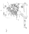
- Fig. 1 has an offset rotary printing machine at least one printing unit 01 with at least one plate cylinder 02, said plate cylinder 02 in the relevant printing unit 01 with a printing cylinder 03 and the impression cylinder 03 in turn with a counter-pressure cylinder 04, wherein a substrate 06, z. B. a web or a sheet in a nip between the printing cylinder 03 and the impression cylinder 04 passed or at least passed.
- the printing material 06 is z. B. - as shown - guided substantially horizontally through the printing unit 01. With an appropriate arrangement of plate cylinder 02, pressure cylinder 03 and impression cylinder 04 but also a vertical guidance of the printing material 06 by the printing unit 01 is possible.
- the printing material 06 is z.
- a material thickness of the printing material 06 is z. In the range of 0.03 mm to 0.8 mm.
- the relevant plate cylinder 02 of the printing unit 01 ink is supplied from an inking unit 07, said inking 07 z. B. is designed as a color zone short inking unit with an anilox roller 08 and a chambered doctor blade 09.
- the recorded by the anilox roller 08 by means of the chambered doctor blade 09 ink is over at least one each only a few, z. B. three rolls having compactor transported to the respective plate cylinder 02, wherein the respective compactor each having at least one ink fountain roller 11 and at least one inking roller 12.
- the relevant printing unit 01 operates z. In a waterless offset printing process, d. H. without the use of a dampening solution, so that in the relevant printing unit 01 no dampening unit is provided.
- the printing unit 01 described is used in the preferred use in packaging printing for the production of very different packaging or is at least usable there, wherein the respective shape and the material of the packaging in question between each successive processed with this offset rotary printing jobs can be very different from each other.
- print jobs for the production of printed products with z. B. round or polygons Shapes of their respective printed images with additional z. B. alternating different print lengths in rapid succession.
- the relevant printing unit 01 must be adapted to the respective requirements in the shortest possible set-up time.
- the practice has shown that especially in packaging printing printed products are often produce their respective print images describe a geometric shape or a contour, each of a rectangle, as z. B.
- each z. B. provided with a tab covers made of a plastic cups with a z. B. round, in particular circular or oval opening to print, as these z. B. for the packaging of dairy products are known.
- z. B. relatively expensive printing material 06
- printing plates 13 have already been used in practice, at least in their respective arranged on a plate cylinder 02 of the printing unit 01 operating state on at least one of its circumferentially located ends 14; 16 are formed in the axial direction of the relevant plate cylinder 02 oddly contoured.
- ends 14; 16 are preferably not angled with respect to a center portion of the pressure plate 13 formed as a planographic printing plate but are stretched in the circumferential direction of the plate cylinder 02.
- Fig. 2a shows by way of example such a pressure plate 13 in its extended length, wherein in this pressure plate 13, both of them with respect to the associated plate cylinder 02 (FIG. Fig. 2b ) circumferentially opposite ends 14; 16 are formed contoured at least in a section odd.
- width of the pressure plate 13 extending contour is curved or curved, with this contour z.
- B. has at least one turning point, preferably several inflection points.
- the odd-contoured contour of the printing plate 13 is dependent on the shape of the printed image of the printed product to be produced trained and thus largely adapted to the shape or contour of the printed image of the printed product to be produced by the offset rotary printing press.
- the width of the respective pressure plate 13 is in the range of z. B. 400 mm to 1,000 mm, preferably at about 800 mm; their stretched length at 500 mm to 1,000 mm or more.
- a material thickness of this form of a planographic printing plate 13 is in the range of z. B. 0.2 mm to 0.5 mm.
- the relevant pressure plate 13 is made of a metallic material, for. B. made of aluminum, and at least their length flexible.
- the respective contour is at the two ends 14; 16 of this pressure plate 13 shown by way of example preferably formed in the same direction, so that these two preferably each over the entire surface of the lateral surface of the relevant plate cylinder 02 adjacent ends 14; 16 of the same printing plate 13 or different but identically shaped printing plates 13 during assembly ( Fig. 2d ) this pressure plate 13 or the various, but at their respective ends 14; 16 in each case uniquely shaped pressure plates 13 without overlapping by a form fit in each case preferably to complement an at least almost closed total area harmoniously ( Fig. 2c ).
- the available surface of the respective printing material 06 is optimally used, ie with as little waste as possible, because only between the respective printed images of the plurality of printed products 06 to be produced very small, ie area minimized, for the printed products unused waste areas remain.
- At least the odd contour contoured ends 14; 16 of the respective pressure plate 13 are attached to the lateral surface of the relevant plate cylinder 02 by means of at least one adhesive layer on the lateral surface of the plate cylinder 02 or at least attachable.
- a layer is here in a planar expansion at a certain height above, below or between other lying uniform material, eg.
- adhesive As adhesive, understood, which is characterized in its embodiment as an adhesive layer by the property of the adhesion, ie. By adhering this substance to an adherend, z. B. at the on the lateral surface of the relevant plate cylinder 02 to be fixed pressure plate concerned. 13
- At least one register member 18 is provided on the plate cylinder 02, which acts on the respective pressure plate 13 and thereby positions this pressure plate 13 relative to the relevant plate cylinder 02.
- At least one register member 18 is provided on the plate cylinder 02, which acts on the respective pressure plate 13 and thereby positions this pressure plate 13 relative to the relevant plate cylinder 02.
- each register element 18 which engage in the assembly of the respective printing plate 13 on the lateral surface of the relevant plate cylinder 02 in each case corresponding to the respective pressure plate 13 spaced-trained recesses 17.
- register elements 18 are each z. B. formed as a rotatable about the respective longitudinal axis pin or as a rotatable about the respective longitudinal axis adjustable disc. By a z. B. eccentric adjustment or by a shift of at least one of these register elements 18 is then arranged on the outer surface of the respective plate cylinder 02 or at least arrangeable pressure plate 13 by registering this pressure plate 13 in register aligned or at least alignable.
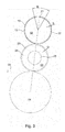
- Fig. 3 shows again in a simplified representation of the printing unit 01 from the Fig. 1 , using the Fig. 3 on details of the plate cylinder 02 and the printing cylinder 03 is received.
- an intermediate layer 19 Radial between the lateral surface of the z. B. as a steel cylinder formed plate cylinder 02 and the at least one arranged on the lateral surface of this plate cylinder 02 metallic pressure plate 13 is provided in the preferred embodiment, an intermediate layer 19, said intermediate layer 19 preferably surrounds the lateral surface of this plate cylinder 02 in its circumferential direction.
- the intermediate layer 19 has a very small layer thickness S z compared to the diameter of the plate cylinder 02. B. of less than 1 mm. These Intermediate layer 19 is z. B.
- this adhesive layer in the axial direction of the relevant plate cylinder 02 z. B. formed in the form of a strip. It is provided that at least one of the odd-lined contoured ends 14; 16 of the respective printing plate 13 on the adhesive layer, in particular in the relevant formed as an adhesive layer first region 21 of the intermediate layer 19 is arranged or at least can be arranged.
- the respective odd-contoured end 14; 16 of the relevant pressure plate 13 is thus preferably solely by means of z. B.
- Adhesion is to be understood here as meaning that the relevant pressure plate 13 is mechanically and / or electrostatically and / or in a polar bond caused by molecular interactions in the interface layer between this pressure plate 13 and the jacket surface of the plate cylinder 02 or the respective first region 21 of the intermediate layer 19 held and thereby held or fastened to the lateral surface of the plate cylinder 02.
- the attachment of the relevant pressure plate 13 on the lateral surface of the plate cylinder 02 is thus preferably carried out with the aid of an adhesive.
- Adhesive is understood to mean a non-metallic material, the parts to be joined, in this case the pressure plate 13 in question, in particular at least one of its ends 14; 16, and z.
- An adhesive may, chemically, be an organic compound or an inorganic compound or a silicone, wherein their respective hardening mechanism may be physically setting or chemically curing. In addition, those adhesives which have no significant strengthening mechanism are particularly advantageous. Adhesives without hardening mechanism are also known as pressure-sensitive adhesives. Pressure-sensitive adhesives remain after their application to a support material, in which case z. B.
- Adhesives can be prepared by means of a carrier material, for. B. in the form of an adhesive tape, or applied without a carrier.
- the adhesive layer provided for fastening the relevant pressure plate 13 to the lateral surface of the plate cylinder 02 is designed as a pressure-sensitive adhesive.
- the extending in the circumferential direction of the plate cylinder 02 on the elbow B first portion 21 passes over an angle in the range between z. B. 15 ° and 120 °, preferably between 80 ° and 105 °. It can be provided that the lateral surface of the plate cylinder 02 in the circumferential direction surrounding intermediate layer 19 along the circumference of this plate cylinder 02 more z. B. in their respective arc length equal or unequal first regions 21 each having an adhesive layer, as shown in the Fig. 4 is shown by a schematic representation of not occupied with a printing plate 23 plate cylinder 02 of the printing unit 01. In the not to scale Fig. 4 are two in the intermediate layer 19 diagonally opposite arranged first regions 21 each shown with an adhesive layer hatched.
- the respective directed in the circumferential direction of the plate cylinder 02 length of the respective elbow B of the respective first region 21 is dependent on the contour of the relevant pressure plate used 13 and selected such that the contour contour in question is completely in the first region 21 can be arranged.
- the lateral surface of the plate cylinder 02 is preferably as a smooth metallic surface and closed, ie at least in the arrangement region of the respective pressure plate 13 z. B. formed without a groove or pit.
- the relevant odd-contoured, from the adhesive layer z. B. in the concerned first portion 21 of the intermediate layer 19 held end 14; 16 of the respective printing plate 13 without residue and without tools detachable from the adhesive layer, and the same adhesive layer is re-usable for re-holding the relevant or another printing plate 13.
- the residue-free detachment of the respective printing plate 13 of the adhesive layer means that when detached from the relevant detached printing plate 13, neither a part of the adhesive layer nor material z. B. from the surface of the intermediate layer 19 or from the lateral surface of the respective plate cylinder 02 stick.
- the respective adhesive layer is preferably each formed as a flexible tacky polymeric film, said film z. B. permanent and / or insoluble, that is nondestructive non-destructive, is glued to the outer surface of the relevant plate cylinder 02.
- the respective adhesive layer is z. B. by applying a cleaning agent, preferably a cleaning liquid regenerable and thus reusable.
- the intermediate layer 19 has at least one second region 22 in which no adhesive layer is provided.
- There is a z. B. metallic foil on the outer surface of the plate cylinder 02 z. B. is also glued, but which is not sticky at least on their contact surface to the respective pressure plate 13.
- the at least one relevant printing plate 13 is thus only partially and not fully held in this embodiment variant on the lateral surface of the plate cylinder 02.
- the z. B. metallic foil in the respective second region 22 and the respective adhesive layer in the respective first region 21 of the respective intermediate layer 19 have, of course, a same radial thickness in order in the printing unit 01 z. B. in cooperation with the impression cylinder 03 does not affect the concentricity of the relevant plate cylinder 02.
- the relevant blanket 23 z. B. formed as a rubber blanket with a arranged on a support compression layer.
- the blanket 23 is z. B.
- the blanket 23 is z. B. formed as a flat, designed in the form of a flexible plate metal blanket.
- the blanket 23 has a thickness D in the range of z. B. 0.5 mm to 1 mm.
- the blanket 23 z. B. in conjunction with a coaxially arranged on an air mandrel cylinder 26 adapter cylinder 24 may be formed variable in size, so that the pressure cylinder 03 depending on the adapter cylinder 24 used each having a different outer diameter.
- the occupied with the at least one blanket 23 printing cylinder 03 is also referred to as a transfer cylinder. If the blanket 23 is contoured in accordance with the contour of the relevant printing plate 13, it is preferably provided that the relevant printing cylinder 03 as well as the plate cylinder 02 cooperating with this printing cylinder 03 has an intermediate layer in the same manner as described above in connection with the plate cylinder 02 , In the printing cylinder 03 z. B.
- At least one of the odd-contoured ends of the respective printing blanket 23 is arranged or at least can be arranged in the respective first region of the intermediate printing layer of the relevant printing cylinder 03 formed as an adhesive layer odd-contoured trained end of the respective blanket 23 is held by means of the existing in the respective first region of the intermediate layer adhesive layer on the lateral surface of the relevant printing cylinder 03.
- the extending over a curved portion first portion of the pressure cylinder 03 enclosing intermediate layer is in the axial direction of this printing cylinder 03 z. B. formed as a strip.
- the printing blanket 23 in question is thus held mechanically and / or electrostatically and / or in a polar bond by the molecular interactions produced in the interface layer between this blanket 23 and the relevant first region of the intermediate layer of the relevant printing cylinder 03, and is thereby fastened to the lateral surface of the printing cylinder 03 becomes.
- the direct or indirect attachment of the blanket 23 concerned on the lateral surface of the relevant printing cylinder 03 is thus preferably carried out with the aid of an adhesive, which applies to this adhesive equivalent, as it was already carried out in connection with the attachment of the at least one pressure plate 13. If necessary, it can be provided that the lateral surface of the relevant printing cylinder 03 in the circumferential direction surrounding intermediate layer along the circumference of this printing cylinder 03 more z. B.
- the respective adhesive layer in the intermediate layer of the relevant printing cylinder 03 is preferably each as a z. B. flexible, sticky polymeric film, this film each z. B. using an adhesive in particular permanently and / or insoluble, that is non-destructively applied non-detachably on the lateral surface of the relevant printing cylinder 03.
- the respective adhesive layer used for the attachment of the respective blanket 23 is z. B. by applying a Cleaning agent, preferably a cleaning liquid regenerable and thus reusable.
- the intermediate layer can also z. B. have at least a second region in which no adhesive layer is provided.
- the z. B. metallic foil in the respective second region and the respective adhesive layer in the respective first region of the respective intermediate layer have a same radial thickness in order in the printing unit 01 z. B. in cooperation with the plate cylinder 02 does not affect the concentricity of the relevant printing cylinder 03.
- the respective contour at the two ends of the printing blanket 23 is preferably formed in the same direction as in the associated printing plate 13, so that these two preferably full-surface on the outer surface of the respective printing cylinder 03 adjacent ends of the same blanket 23 or different, but identically designed blankets 23 without overlap preferably harmoniously complement each other by an interlocking to an at least almost closed total area.
- a printing unit 01 an offset rotary printing press with a plate cylinder 02, wherein on the lateral surface of the plate cylinder 02 at least one formed as a planographic printing plate 13 is arranged or at least arranged, said at least one pressure plate 13 at least one of its circumferentially located ends 14; 16 is formed in the axial direction of this plate cylinder 02 at least in a section oddly contoured, wherein the curved over a directed in the axial direction of the relevant plate cylinder 02 width of the respective pressure plate 13 contour curved or bent, wherein the over the width of the respective pressure plate 13 extending contour in the preferred embodiment has at least one turning point or in particular several turning points.
- the odd-line contour of the relevant printing plate 13 is in response to a shape or contour of a printed image of the Offsetrotationsdruckmaschine to be produced printed product, wherein the respective contour of the respective printing plate 13 is respectively adapted to the shape or contour of the relevant printed image in question, wherein the relevant printing plate 13 at least one printed image with a z. B. round or polygonal shape and / or z. B. has printed images of different print length.
- the at least one pressure plate 13 is preferably fixed by means of an adhesive layer on the lateral surface of the plate cylinder 02 or at least attachable.
- a lateral surface of this plate cylinder 02 in the circumferential direction preferably surrounding intermediate layer 19, said intermediate layer 19 in a design variant in a circumferentially the plate cylinder 02 at least over a bend B extending first portion 21 has the adhesive layer, wherein at the respective adhesive layer at least one of the odd-contoured shaped ends 14; 16 of the respective printing plate 02 is arranged or at least can be arranged, wherein the respective odd-contoured formed end 14; 16 of the relevant printing plate 02 by means of z. B.
- a counter-pressure cylinder 04 and cooperating with the relevant plate cylinder 02 pressure cylinder 03 are provided in a known manner, but preferably on the outer surface of this printing cylinder 03 either also a corresponding contour of the respective printing plate 13 contoured blanket 23 or as a seamless sleeve trained blanket 23 is arranged.
- the odd-contoured Blanket 23 of the respective printing cylinder 03 and cooperating with this printing cylinder 03 plate cylinder 02 each have an intermediate layer, wherein in the pressure cylinder 03 preferably enclosing intermediate layer in an extending in the circumferential direction of the printing cylinder 03 at least over a curved portion extending first area an adhesive layer, wherein in the relevant formed as an adhesive layer first region of the intermediate layer of the respective printing cylinder 03 at least one of the odd contoured ends of the respective blanket 23 is arranged or at least can be arranged.
Landscapes
- Engineering & Computer Science (AREA)
- Mechanical Engineering (AREA)
- Printing Plates And Materials Therefor (AREA)
Applications Claiming Priority (1)
| Application Number | Priority Date | Filing Date | Title |
|---|---|---|---|
| DE102013222175.4A DE102013222175B4 (de) | 2013-10-31 | 2013-10-31 | Druckwerk einer Offsetrotationsdruckmaschine |
Publications (3)
| Publication Number | Publication Date |
|---|---|
| EP2868471A2 true EP2868471A2 (fr) | 2015-05-06 |
| EP2868471A3 EP2868471A3 (fr) | 2015-06-03 |
| EP2868471B1 EP2868471B1 (fr) | 2015-10-28 |
Family
ID=51660398
Family Applications (1)
| Application Number | Title | Priority Date | Filing Date |
|---|---|---|---|
| EP14188098.9A Not-in-force EP2868471B1 (fr) | 2013-10-31 | 2014-10-08 | Imprimé d'une machine offset rotative |
Country Status (2)
| Country | Link |
|---|---|
| EP (1) | EP2868471B1 (fr) |
| DE (1) | DE102013222175B4 (fr) |
Cited By (1)
| Publication number | Priority date | Publication date | Assignee | Title |
|---|---|---|---|---|
| US11691408B2 (en) | 2020-05-26 | 2023-07-04 | Esko Software Bv | System and method for designing and creating a printing plate |
Citations (7)
| Publication number | Priority date | Publication date | Assignee | Title |
|---|---|---|---|---|
| US3358598A (en) | 1966-01-27 | 1967-12-19 | Middleton John O'brien | Method of mounting plates to printing machine cylinders |
| US4643094A (en) | 1984-12-05 | 1987-02-17 | Tetra Pak International Ab | Printing plate for offset printing |
| DE4323750A1 (de) | 1993-07-15 | 1995-01-26 | Roland Man Druckmasch | Offset-Druckform und Verfahren zur Herstellung einer solchen Offset-Druckform |
| DE19529809A1 (de) | 1995-08-14 | 1997-02-20 | Westland Gummiwerke Gmbh & Co | Walze für Farbverarbeitung |
| DE69500578T2 (de) | 1994-01-13 | 1998-04-02 | Winkle Holding B.V., Amsersfoort | Befestigungsmittel |
| WO2004016432A1 (fr) | 2002-07-18 | 2004-02-26 | Koenig & Bauer Aktiengesellschaft | Cylindre porte-cliche pour machine d'imprimerie |
| WO2011015480A1 (fr) | 2009-08-04 | 2011-02-10 | Kba-Metronic Aktiengesellschaft | Douille d'un cylindre |
Family Cites Families (1)
| Publication number | Priority date | Publication date | Assignee | Title |
|---|---|---|---|---|
| NL1027555C2 (nl) * | 2004-11-19 | 2006-05-22 | Drent Holding B V | Beeldoverdrachthuls, en offsetdrukpers, voorzien van een dergelijke beeldoverdrachthuls. |
-
2013
- 2013-10-31 DE DE102013222175.4A patent/DE102013222175B4/de not_active Expired - Fee Related
-
2014
- 2014-10-08 EP EP14188098.9A patent/EP2868471B1/fr not_active Not-in-force
Patent Citations (7)
| Publication number | Priority date | Publication date | Assignee | Title |
|---|---|---|---|---|
| US3358598A (en) | 1966-01-27 | 1967-12-19 | Middleton John O'brien | Method of mounting plates to printing machine cylinders |
| US4643094A (en) | 1984-12-05 | 1987-02-17 | Tetra Pak International Ab | Printing plate for offset printing |
| DE4323750A1 (de) | 1993-07-15 | 1995-01-26 | Roland Man Druckmasch | Offset-Druckform und Verfahren zur Herstellung einer solchen Offset-Druckform |
| DE69500578T2 (de) | 1994-01-13 | 1998-04-02 | Winkle Holding B.V., Amsersfoort | Befestigungsmittel |
| DE19529809A1 (de) | 1995-08-14 | 1997-02-20 | Westland Gummiwerke Gmbh & Co | Walze für Farbverarbeitung |
| WO2004016432A1 (fr) | 2002-07-18 | 2004-02-26 | Koenig & Bauer Aktiengesellschaft | Cylindre porte-cliche pour machine d'imprimerie |
| WO2011015480A1 (fr) | 2009-08-04 | 2011-02-10 | Kba-Metronic Aktiengesellschaft | Douille d'un cylindre |
Cited By (1)
| Publication number | Priority date | Publication date | Assignee | Title |
|---|---|---|---|---|
| US11691408B2 (en) | 2020-05-26 | 2023-07-04 | Esko Software Bv | System and method for designing and creating a printing plate |
Also Published As
| Publication number | Publication date |
|---|---|
| DE102013222175B4 (de) | 2017-11-09 |
| DE102013222175A1 (de) | 2015-04-30 |
| EP2868471A3 (fr) | 2015-06-03 |
| EP2868471B1 (fr) | 2015-10-28 |
Similar Documents
| Publication | Publication Date | Title |
|---|---|---|
| EP0936065B1 (fr) | Dispositif pour appliquer un liquide sur une feuille imprimé, notamment unité d'impression ou de lacquage dans une machine rotative d'impression pour feuilles | |
| EP0581019B1 (fr) | Blanchet pour machine à imprimer en offset | |
| DE4323750C2 (de) | Offset-Druckform und Verfahren zur Herstellung einer solchen Offset-Druckform | |
| EP1157855B1 (fr) | Manchon à base de caoutchouc, notamment pour machines rotatives offset | |
| DE4320464A1 (de) | Übertragungszylinder für Rotationsdruckmaschinen | |
| DE102016201137A1 (de) | Vorrichtung zum Bedrucken von Hohlkörpern | |
| DE102019123631A1 (de) | Farbwerk einer Druckmaschine | |
| EP2868471B1 (fr) | Imprimé d'une machine offset rotative | |
| EP0279295B1 (fr) | Unité d'encrage | |
| DE102006030062B3 (de) | Bogenführungszylinder mit Aufzug in einer Verarbeitungsmaschine | |
| DE19950643A1 (de) | Gummizylinderhülse, insbesondere für Offset-Rollenrotationsdruckmaschinen | |
| EP1341669B1 (fr) | Dispositif de vernissage pour rotative a imprimer | |
| EP1645433B1 (fr) | Manchon pour un cylindre d'une machine d'impression | |
| EP1368197B1 (fr) | Procede et dispositifs servant a preparer un cylindre d'impression a l'impression | |
| WO2010089215A1 (fr) | Procédé et dispositif de façonnage d'un support d'impression dans une machine de traitement | |
| EP2377686B1 (fr) | Manchon à monter sur un cylindre de machine d'impression | |
| DE102013103712A1 (de) | Druckwerk und Gummituchplatte für ein Druckwerk | |
| EP1724114B1 (fr) | Machine d'impression rotative avec au moins un groupe d'impression | |
| DE102007010433B4 (de) | Druckwerk | |
| EP1989052A1 (fr) | Machine d'impression | |
| DE10232551B4 (de) | Formzylinder für eine Druckmaschine | |
| EP2829402A2 (fr) | Unité d'impression offset et habillage pour le blanchet | |
| DE102022103265A1 (de) | Druckeinheit einer Rollendruckmaschine, Rollendruckmaschine, Verfahren und Verwendung derselben | |
| DE102016201139A1 (de) | Vorrichtung zum Bedrucken von Hohlkörpern | |
| DE20102450U1 (de) | Lackiervorrichtung für eine Rotationsdruckmaschine |
Legal Events
| Date | Code | Title | Description |
|---|---|---|---|
| PUAL | Search report despatched |
Free format text: ORIGINAL CODE: 0009013 |
|
| PUAI | Public reference made under article 153(3) epc to a published international application that has entered the european phase |
Free format text: ORIGINAL CODE: 0009012 |
|
| 17P | Request for examination filed |
Effective date: 20141008 |
|
| AK | Designated contracting states |
Kind code of ref document: A2 Designated state(s): AL AT BE BG CH CY CZ DE DK EE ES FI FR GB GR HR HU IE IS IT LI LT LU LV MC MK MT NL NO PL PT RO RS SE SI SK SM TR |
|
| AX | Request for extension of the european patent |
Extension state: BA ME |
|
| AK | Designated contracting states |
Kind code of ref document: A3 Designated state(s): AL AT BE BG CH CY CZ DE DK EE ES FI FR GB GR HR HU IE IS IT LI LT LU LV MC MK MT NL NO PL PT RO RS SE SI SK SM TR |
|
| AX | Request for extension of the european patent |
Extension state: BA ME |
|
| RIC1 | Information provided on ipc code assigned before grant |
Ipc: B41C 1/18 20060101ALI20150424BHEP Ipc: B41N 1/04 20060101ALI20150424BHEP Ipc: B41F 27/12 20060101AFI20150424BHEP Ipc: B41N 1/20 20060101ALI20150424BHEP Ipc: B41N 1/08 20060101ALI20150424BHEP |
|
| R17P | Request for examination filed (corrected) |
Effective date: 20150522 |
|
| GRAP | Despatch of communication of intention to grant a patent |
Free format text: ORIGINAL CODE: EPIDOSNIGR1 |
|
| INTG | Intention to grant announced |
Effective date: 20150716 |
|
| GRAS | Grant fee paid |
Free format text: ORIGINAL CODE: EPIDOSNIGR3 |
|
| GRAA | (expected) grant |
Free format text: ORIGINAL CODE: 0009210 |
|
| AK | Designated contracting states |
Kind code of ref document: B1 Designated state(s): AL AT BE BG CH CY CZ DE DK EE ES FI FR GB GR HR HU IE IS IT LI LT LU LV MC MK MT NL NO PL PT RO RS SE SI SK SM TR |
|
| REG | Reference to a national code |
Ref country code: GB Ref legal event code: FG4D Free format text: NOT ENGLISH |
|
| REG | Reference to a national code |
Ref country code: CH Ref legal event code: EP |
|
| REG | Reference to a national code |
Ref country code: AT Ref legal event code: REF Ref document number: 757707 Country of ref document: AT Kind code of ref document: T Effective date: 20151115 |
|
| REG | Reference to a national code |
Ref country code: IE Ref legal event code: FG4D Free format text: LANGUAGE OF EP DOCUMENT: GERMAN |
|
| REG | Reference to a national code |
Ref country code: DE Ref legal event code: R096 Ref document number: 502014000172 Country of ref document: DE |
|
| REG | Reference to a national code |
Ref country code: LT Ref legal event code: MG4D |
|
| REG | Reference to a national code |
Ref country code: NL Ref legal event code: MP Effective date: 20151028 |
|
| PG25 | Lapsed in a contracting state [announced via postgrant information from national office to epo] |
Ref country code: LT Free format text: LAPSE BECAUSE OF FAILURE TO SUBMIT A TRANSLATION OF THE DESCRIPTION OR TO PAY THE FEE WITHIN THE PRESCRIBED TIME-LIMIT Effective date: 20151028 Ref country code: NO Free format text: LAPSE BECAUSE OF FAILURE TO SUBMIT A TRANSLATION OF THE DESCRIPTION OR TO PAY THE FEE WITHIN THE PRESCRIBED TIME-LIMIT Effective date: 20160128 Ref country code: ES Free format text: LAPSE BECAUSE OF FAILURE TO SUBMIT A TRANSLATION OF THE DESCRIPTION OR TO PAY THE FEE WITHIN THE PRESCRIBED TIME-LIMIT Effective date: 20151028 Ref country code: HR Free format text: LAPSE BECAUSE OF FAILURE TO SUBMIT A TRANSLATION OF THE DESCRIPTION OR TO PAY THE FEE WITHIN THE PRESCRIBED TIME-LIMIT Effective date: 20151028 Ref country code: NL Free format text: LAPSE BECAUSE OF FAILURE TO SUBMIT A TRANSLATION OF THE DESCRIPTION OR TO PAY THE FEE WITHIN THE PRESCRIBED TIME-LIMIT Effective date: 20151028 Ref country code: IS Free format text: LAPSE BECAUSE OF FAILURE TO SUBMIT A TRANSLATION OF THE DESCRIPTION OR TO PAY THE FEE WITHIN THE PRESCRIBED TIME-LIMIT Effective date: 20160228 Ref country code: IT Free format text: LAPSE BECAUSE OF FAILURE TO SUBMIT A TRANSLATION OF THE DESCRIPTION OR TO PAY THE FEE WITHIN THE PRESCRIBED TIME-LIMIT Effective date: 20151028 |
|
| PG25 | Lapsed in a contracting state [announced via postgrant information from national office to epo] |
Ref country code: FI Free format text: LAPSE BECAUSE OF FAILURE TO SUBMIT A TRANSLATION OF THE DESCRIPTION OR TO PAY THE FEE WITHIN THE PRESCRIBED TIME-LIMIT Effective date: 20151028 Ref country code: GR Free format text: LAPSE BECAUSE OF FAILURE TO SUBMIT A TRANSLATION OF THE DESCRIPTION OR TO PAY THE FEE WITHIN THE PRESCRIBED TIME-LIMIT Effective date: 20160129 Ref country code: SE Free format text: LAPSE BECAUSE OF FAILURE TO SUBMIT A TRANSLATION OF THE DESCRIPTION OR TO PAY THE FEE WITHIN THE PRESCRIBED TIME-LIMIT Effective date: 20151028 Ref country code: PT Free format text: LAPSE BECAUSE OF FAILURE TO SUBMIT A TRANSLATION OF THE DESCRIPTION OR TO PAY THE FEE WITHIN THE PRESCRIBED TIME-LIMIT Effective date: 20160229 Ref country code: RS Free format text: LAPSE BECAUSE OF FAILURE TO SUBMIT A TRANSLATION OF THE DESCRIPTION OR TO PAY THE FEE WITHIN THE PRESCRIBED TIME-LIMIT Effective date: 20151028 Ref country code: PL Free format text: LAPSE BECAUSE OF FAILURE TO SUBMIT A TRANSLATION OF THE DESCRIPTION OR TO PAY THE FEE WITHIN THE PRESCRIBED TIME-LIMIT Effective date: 20151028 Ref country code: LV Free format text: LAPSE BECAUSE OF FAILURE TO SUBMIT A TRANSLATION OF THE DESCRIPTION OR TO PAY THE FEE WITHIN THE PRESCRIBED TIME-LIMIT Effective date: 20151028 |
|
| REG | Reference to a national code |
Ref country code: CH Ref legal event code: PUE Owner name: KOENIG AND BAUER AG, DE Free format text: FORMER OWNER: KBA-MEPRINT AG, DE |
|
| REG | Reference to a national code |
Ref country code: DE Ref legal event code: R081 Ref document number: 502014000172 Country of ref document: DE Owner name: KOENIG & BAUER AG, DE Free format text: FORMER OWNER: KBA-MEPRINT AG, 97209 VEITSHOECHHEIM, DE |
|
| PG25 | Lapsed in a contracting state [announced via postgrant information from national office to epo] |
Ref country code: CZ Free format text: LAPSE BECAUSE OF FAILURE TO SUBMIT A TRANSLATION OF THE DESCRIPTION OR TO PAY THE FEE WITHIN THE PRESCRIBED TIME-LIMIT Effective date: 20151028 |
|
| REG | Reference to a national code |
Ref country code: DE Ref legal event code: R097 Ref document number: 502014000172 Country of ref document: DE |
|
| PG25 | Lapsed in a contracting state [announced via postgrant information from national office to epo] |
Ref country code: DK Free format text: LAPSE BECAUSE OF FAILURE TO SUBMIT A TRANSLATION OF THE DESCRIPTION OR TO PAY THE FEE WITHIN THE PRESCRIBED TIME-LIMIT Effective date: 20151028 Ref country code: EE Free format text: LAPSE BECAUSE OF FAILURE TO SUBMIT A TRANSLATION OF THE DESCRIPTION OR TO PAY THE FEE WITHIN THE PRESCRIBED TIME-LIMIT Effective date: 20151028 Ref country code: SK Free format text: LAPSE BECAUSE OF FAILURE TO SUBMIT A TRANSLATION OF THE DESCRIPTION OR TO PAY THE FEE WITHIN THE PRESCRIBED TIME-LIMIT Effective date: 20151028 Ref country code: RO Free format text: LAPSE BECAUSE OF FAILURE TO SUBMIT A TRANSLATION OF THE DESCRIPTION OR TO PAY THE FEE WITHIN THE PRESCRIBED TIME-LIMIT Effective date: 20151028 Ref country code: SM Free format text: LAPSE BECAUSE OF FAILURE TO SUBMIT A TRANSLATION OF THE DESCRIPTION OR TO PAY THE FEE WITHIN THE PRESCRIBED TIME-LIMIT Effective date: 20151028 |
|
| PLBE | No opposition filed within time limit |
Free format text: ORIGINAL CODE: 0009261 |
|
| STAA | Information on the status of an ep patent application or granted ep patent |
Free format text: STATUS: NO OPPOSITION FILED WITHIN TIME LIMIT |
|
| RAP2 | Party data changed (patent owner data changed or rights of a patent transferred) |
Owner name: KOENIG & BAUER AG |
|
| 26N | No opposition filed |
Effective date: 20160729 |
|
| REG | Reference to a national code |
Ref country code: FR Ref legal event code: PLFP Year of fee payment: 3 |
|
| PG25 | Lapsed in a contracting state [announced via postgrant information from national office to epo] |
Ref country code: SI Free format text: LAPSE BECAUSE OF FAILURE TO SUBMIT A TRANSLATION OF THE DESCRIPTION OR TO PAY THE FEE WITHIN THE PRESCRIBED TIME-LIMIT Effective date: 20151028 |
|
| PG25 | Lapsed in a contracting state [announced via postgrant information from national office to epo] |
Ref country code: BE Free format text: LAPSE BECAUSE OF NON-PAYMENT OF DUE FEES Effective date: 20161031 |
|
| PG25 | Lapsed in a contracting state [announced via postgrant information from national office to epo] |
Ref country code: MC Free format text: LAPSE BECAUSE OF FAILURE TO SUBMIT A TRANSLATION OF THE DESCRIPTION OR TO PAY THE FEE WITHIN THE PRESCRIBED TIME-LIMIT Effective date: 20151028 |
|
| REG | Reference to a national code |
Ref country code: IE Ref legal event code: MM4A |
|
| PG25 | Lapsed in a contracting state [announced via postgrant information from national office to epo] |
Ref country code: LU Free format text: LAPSE BECAUSE OF NON-PAYMENT OF DUE FEES Effective date: 20161008 |
|
| REG | Reference to a national code |
Ref country code: FR Ref legal event code: PLFP Year of fee payment: 4 |
|
| PG25 | Lapsed in a contracting state [announced via postgrant information from national office to epo] |
Ref country code: IE Free format text: LAPSE BECAUSE OF NON-PAYMENT OF DUE FEES Effective date: 20161008 |
|
| REG | Reference to a national code |
Ref country code: BE Ref legal event code: MM Effective date: 20161031 |
|
| PG25 | Lapsed in a contracting state [announced via postgrant information from national office to epo] |
Ref country code: HU Free format text: LAPSE BECAUSE OF FAILURE TO SUBMIT A TRANSLATION OF THE DESCRIPTION OR TO PAY THE FEE WITHIN THE PRESCRIBED TIME-LIMIT; INVALID AB INITIO Effective date: 20141008 |
|
| PG25 | Lapsed in a contracting state [announced via postgrant information from national office to epo] |
Ref country code: MK Free format text: LAPSE BECAUSE OF FAILURE TO SUBMIT A TRANSLATION OF THE DESCRIPTION OR TO PAY THE FEE WITHIN THE PRESCRIBED TIME-LIMIT Effective date: 20151028 Ref country code: CY Free format text: LAPSE BECAUSE OF FAILURE TO SUBMIT A TRANSLATION OF THE DESCRIPTION OR TO PAY THE FEE WITHIN THE PRESCRIBED TIME-LIMIT Effective date: 20151028 Ref country code: MT Free format text: LAPSE BECAUSE OF FAILURE TO SUBMIT A TRANSLATION OF THE DESCRIPTION OR TO PAY THE FEE WITHIN THE PRESCRIBED TIME-LIMIT Effective date: 20151028 |
|
| PG25 | Lapsed in a contracting state [announced via postgrant information from national office to epo] |
Ref country code: BG Free format text: LAPSE BECAUSE OF FAILURE TO SUBMIT A TRANSLATION OF THE DESCRIPTION OR TO PAY THE FEE WITHIN THE PRESCRIBED TIME-LIMIT Effective date: 20151028 |
|
| REG | Reference to a national code |
Ref country code: FR Ref legal event code: PLFP Year of fee payment: 5 |
|
| PG25 | Lapsed in a contracting state [announced via postgrant information from national office to epo] |
Ref country code: TR Free format text: LAPSE BECAUSE OF FAILURE TO SUBMIT A TRANSLATION OF THE DESCRIPTION OR TO PAY THE FEE WITHIN THE PRESCRIBED TIME-LIMIT Effective date: 20151028 Ref country code: AL Free format text: LAPSE BECAUSE OF FAILURE TO SUBMIT A TRANSLATION OF THE DESCRIPTION OR TO PAY THE FEE WITHIN THE PRESCRIBED TIME-LIMIT Effective date: 20151028 |
|
| PGFP | Annual fee paid to national office [announced via postgrant information from national office to epo] |
Ref country code: GB Payment date: 20181024 Year of fee payment: 4 Ref country code: FR Payment date: 20181026 Year of fee payment: 5 |
|
| PGFP | Annual fee paid to national office [announced via postgrant information from national office to epo] |
Ref country code: DE Payment date: 20191108 Year of fee payment: 6 |
|
| PGFP | Annual fee paid to national office [announced via postgrant information from national office to epo] |
Ref country code: CH Payment date: 20191025 Year of fee payment: 6 |
|
| GBPC | Gb: european patent ceased through non-payment of renewal fee |
Effective date: 20191008 |
|
| PG25 | Lapsed in a contracting state [announced via postgrant information from national office to epo] |
Ref country code: FR Free format text: LAPSE BECAUSE OF NON-PAYMENT OF DUE FEES Effective date: 20191031 Ref country code: GB Free format text: LAPSE BECAUSE OF NON-PAYMENT OF DUE FEES Effective date: 20191008 |
|
| REG | Reference to a national code |
Ref country code: AT Ref legal event code: MM01 Ref document number: 757707 Country of ref document: AT Kind code of ref document: T Effective date: 20191008 |
|
| PG25 | Lapsed in a contracting state [announced via postgrant information from national office to epo] |
Ref country code: AT Free format text: LAPSE BECAUSE OF NON-PAYMENT OF DUE FEES Effective date: 20191008 |
|
| REG | Reference to a national code |
Ref country code: DE Ref legal event code: R119 Ref document number: 502014000172 Country of ref document: DE |
|
| REG | Reference to a national code |
Ref country code: CH Ref legal event code: PL |
|
| PG25 | Lapsed in a contracting state [announced via postgrant information from national office to epo] |
Ref country code: DE Free format text: LAPSE BECAUSE OF NON-PAYMENT OF DUE FEES Effective date: 20210501 |
|
| PG25 | Lapsed in a contracting state [announced via postgrant information from national office to epo] |
Ref country code: LI Free format text: LAPSE BECAUSE OF NON-PAYMENT OF DUE FEES Effective date: 20201031 Ref country code: CH Free format text: LAPSE BECAUSE OF NON-PAYMENT OF DUE FEES Effective date: 20201031 |