EP2869018A1 - Verdampfer mit einer hybriden Expansionsvorrichtung für verbessertes Aufteilen von Kältemittel - Google Patents
Verdampfer mit einer hybriden Expansionsvorrichtung für verbessertes Aufteilen von Kältemittel Download PDFInfo
- Publication number
- EP2869018A1 EP2869018A1 EP20140189144 EP14189144A EP2869018A1 EP 2869018 A1 EP2869018 A1 EP 2869018A1 EP 20140189144 EP20140189144 EP 20140189144 EP 14189144 A EP14189144 A EP 14189144A EP 2869018 A1 EP2869018 A1 EP 2869018A1
- Authority
- EP
- European Patent Office
- Prior art keywords
- refrigerant
- mixture
- tube
- pressure drop
- evaporator
- Prior art date
- Legal status (The legal status is an assumption and is not a legal conclusion. Google has not performed a legal analysis and makes no representation as to the accuracy of the status listed.)
- Granted
Links
- 239000003507 refrigerant Substances 0.000 title claims abstract description 199
- 238000011166 aliquoting Methods 0.000 title claims description 14
- 239000000203 mixture Substances 0.000 claims abstract description 57
- 239000012071 phase Substances 0.000 claims abstract description 54
- 239000007788 liquid Substances 0.000 claims abstract description 39
- 239000007791 liquid phase Substances 0.000 claims abstract description 29
- 230000005484 gravity Effects 0.000 claims description 9
- 238000004891 communication Methods 0.000 claims description 2
- 239000003570 air Substances 0.000 description 10
- 238000011144 upstream manufacturing Methods 0.000 description 7
- 238000004378 air conditioning Methods 0.000 description 6
- 230000008901 benefit Effects 0.000 description 3
- 239000012808 vapor phase Substances 0.000 description 3
- LVGUZGTVOIAKKC-UHFFFAOYSA-N 1,1,1,2-tetrafluoroethane Chemical compound FCC(F)(F)F LVGUZGTVOIAKKC-UHFFFAOYSA-N 0.000 description 2
- 239000012080 ambient air Substances 0.000 description 2
- 238000013461 design Methods 0.000 description 2
- 230000007246 mechanism Effects 0.000 description 2
- 238000000034 method Methods 0.000 description 2
- 230000008569 process Effects 0.000 description 2
- 230000009467 reduction Effects 0.000 description 2
- 238000012546 transfer Methods 0.000 description 2
- 230000001052 transient effect Effects 0.000 description 2
- 229910000838 Al alloy Inorganic materials 0.000 description 1
- 230000015556 catabolic process Effects 0.000 description 1
- 230000001143 conditioned effect Effects 0.000 description 1
- 230000003750 conditioning effect Effects 0.000 description 1
- 239000004020 conductor Substances 0.000 description 1
- 238000010276 construction Methods 0.000 description 1
- 238000001816 cooling Methods 0.000 description 1
- 238000006731 degradation reaction Methods 0.000 description 1
- 238000006073 displacement reaction Methods 0.000 description 1
- 230000000694 effects Effects 0.000 description 1
- 238000010438 heat treatment Methods 0.000 description 1
- 230000014759 maintenance of location Effects 0.000 description 1
- 238000012986 modification Methods 0.000 description 1
- 230000004048 modification Effects 0.000 description 1
- 239000002245 particle Substances 0.000 description 1
- 238000009877 rendering Methods 0.000 description 1
- 238000000926 separation method Methods 0.000 description 1
- 238000009423 ventilation Methods 0.000 description 1
Images

Classifications
-
- F—MECHANICAL ENGINEERING; LIGHTING; HEATING; WEAPONS; BLASTING
- F25—REFRIGERATION OR COOLING; COMBINED HEATING AND REFRIGERATION SYSTEMS; HEAT PUMP SYSTEMS; MANUFACTURE OR STORAGE OF ICE; LIQUEFACTION SOLIDIFICATION OF GASES
- F25B—REFRIGERATION MACHINES, PLANTS OR SYSTEMS; COMBINED HEATING AND REFRIGERATION SYSTEMS; HEAT PUMP SYSTEMS
- F25B39/00—Evaporators; Condensers
- F25B39/02—Evaporators
- F25B39/028—Evaporators having distributing means
-
- F—MECHANICAL ENGINEERING; LIGHTING; HEATING; WEAPONS; BLASTING
- F25—REFRIGERATION OR COOLING; COMBINED HEATING AND REFRIGERATION SYSTEMS; HEAT PUMP SYSTEMS; MANUFACTURE OR STORAGE OF ICE; LIQUEFACTION SOLIDIFICATION OF GASES
- F25B—REFRIGERATION MACHINES, PLANTS OR SYSTEMS; COMBINED HEATING AND REFRIGERATION SYSTEMS; HEAT PUMP SYSTEMS
- F25B39/00—Evaporators; Condensers
- F25B39/02—Evaporators
-
- F—MECHANICAL ENGINEERING; LIGHTING; HEATING; WEAPONS; BLASTING
- F28—HEAT EXCHANGE IN GENERAL
- F28F—DETAILS OF HEAT-EXCHANGE AND HEAT-TRANSFER APPARATUS, OF GENERAL APPLICATION
- F28F9/00—Casings; Header boxes; Auxiliary supports for elements; Auxiliary members within casings
- F28F9/02—Header boxes; End plates
- F28F9/026—Header boxes; End plates with static flow control means, e.g. with means for uniformly distributing heat exchange media into conduits
- F28F9/027—Header boxes; End plates with static flow control means, e.g. with means for uniformly distributing heat exchange media into conduits in the form of distribution pipes
- F28F9/0273—Header boxes; End plates with static flow control means, e.g. with means for uniformly distributing heat exchange media into conduits in the form of distribution pipes with multiple holes
-
- F—MECHANICAL ENGINEERING; LIGHTING; HEATING; WEAPONS; BLASTING
- F25—REFRIGERATION OR COOLING; COMBINED HEATING AND REFRIGERATION SYSTEMS; HEAT PUMP SYSTEMS; MANUFACTURE OR STORAGE OF ICE; LIQUEFACTION SOLIDIFICATION OF GASES
- F25B—REFRIGERATION MACHINES, PLANTS OR SYSTEMS; COMBINED HEATING AND REFRIGERATION SYSTEMS; HEAT PUMP SYSTEMS
- F25B2341/00—Details of ejectors not being used as compression device; Details of flow restrictors or expansion valves
- F25B2341/06—Details of flow restrictors or expansion valves
-
- F—MECHANICAL ENGINEERING; LIGHTING; HEATING; WEAPONS; BLASTING
- F25—REFRIGERATION OR COOLING; COMBINED HEATING AND REFRIGERATION SYSTEMS; HEAT PUMP SYSTEMS; MANUFACTURE OR STORAGE OF ICE; LIQUEFACTION SOLIDIFICATION OF GASES
- F25B—REFRIGERATION MACHINES, PLANTS OR SYSTEMS; COMBINED HEATING AND REFRIGERATION SYSTEMS; HEAT PUMP SYSTEMS
- F25B2500/00—Problems to be solved
- F25B2500/18—Optimization, e.g. high integration of refrigeration components
-
- F—MECHANICAL ENGINEERING; LIGHTING; HEATING; WEAPONS; BLASTING
- F25—REFRIGERATION OR COOLING; COMBINED HEATING AND REFRIGERATION SYSTEMS; HEAT PUMP SYSTEMS; MANUFACTURE OR STORAGE OF ICE; LIQUEFACTION SOLIDIFICATION OF GASES
- F25B—REFRIGERATION MACHINES, PLANTS OR SYSTEMS; COMBINED HEATING AND REFRIGERATION SYSTEMS; HEAT PUMP SYSTEMS
- F25B41/00—Fluid-circulation arrangements
- F25B41/30—Expansion means; Dispositions thereof
- F25B41/39—Dispositions with two or more expansion means arranged in series, i.e. multi-stage expansion, on a refrigerant line leading to the same evaporator
-
- F—MECHANICAL ENGINEERING; LIGHTING; HEATING; WEAPONS; BLASTING
- F28—HEAT EXCHANGE IN GENERAL
- F28F—DETAILS OF HEAT-EXCHANGE AND HEAT-TRANSFER APPARATUS, OF GENERAL APPLICATION
- F28F9/00—Casings; Header boxes; Auxiliary supports for elements; Auxiliary members within casings
- F28F9/02—Header boxes; End plates
- F28F9/026—Header boxes; End plates with static flow control means, e.g. with means for uniformly distributing heat exchange media into conduits
- F28F9/027—Header boxes; End plates with static flow control means, e.g. with means for uniformly distributing heat exchange media into conduits in the form of distribution pipes
Definitions
- the present disclosure relates to an automotive evaporator; more particularly to a refrigerant expansion device for aliquoting a refrigerant through the refrigerant tubes of the automotive evaporator.
- An air-conditioning system for a motor vehicle typically includes a refrigerant loop having an evaporator located within a heating, ventilation, and air-conditioning (HVAC) module for supplying conditioned air to the passenger compartment, an expansion device located upstream of the evaporator, a condenser located upstream of the expansion device in front of the engine compartment, and a compressor located within the engine compartment upstream of the condenser.
- HVAC heating, ventilation, and air-conditioning
- the compressor compresses and circulates a refrigerant through the closed refrigerant loop.
- a low pressure two phase refrigerant having mixture of liquid and vapor enters the evaporator and flows through the refrigerant tubes of the evaporator where it expands into a low pressure vapor refrigerant by absorbing heat from an incoming air stream.
- the low pressure vapor refrigerant then exits the outlet of the evaporator and enters the compressor where it is compressed into a high pressure high temperature vapor.
- the high pressure vapor refrigerant then flows through the condenser where it condenses into a high pressure liquid refrigerant by releasing the heat to the ambient air outside the motor vehicle.
- the condensed high pressure liquid refrigerant is returned to the evaporator through the expansion device, which expands the high pressure liquid refrigerant to a low pressure mixture of liquid-vapor refrigerant to repeat the cycle.
- a conventional evaporator includes an inlet manifold, an outlet manifold, and a plurality of refrigerant tubes hydraulically connecting the manifolds. Additionally, there may be one or more intermediate manifolds, such as a return manifold, between the inlet and outlet manifold.
- the flow rate of refrigerant through the evaporator typically in the range of 25 to 300 kg/hr for an R-134a refrigerant, depends predominantly on the rotational speed of the engine of the motor vehicle measured in revolutions per minute (rpm). This is a result of the compressor being driven directly by the engine via an accessory belt; hence, the compressor speed changes with the engine rpm.
- the two-phase refrigerant to the refrigerant tubes of the evaporator to provide uniform cooling of the airstream. If the two-phase refrigerant enters the inlet manifold at a relatively high velocity, the liquid phase of the refrigerant is carried by momentum of the flow further away from the entrance of the inlet manifold to the distal end of the inlet manifold. Hence, the refrigerant tubes closest to the inlet manifold entrance receive predominantly the vapor phase and the refrigerant tubes near the distal end of the inlet manifold receive predominantly the liquid phase.
- the refrigerant tubes closest to the inlet manifold entrance receives predominantly the liquid phase and the refrigerant tubes near the distal end of the inlet manifold receives predominantly the vapor phase.
- This is especially true as it relates to the mass fraction of refrigerant compared to the volume fraction. In either case, this results in the misaliquoting of the refrigerant flowing through the refrigerant tube causing degradation in the heat transfer efficiency of the evaporator.
- An undesirable effect of misaliquoting of the liquid refrigerant is the skewing of the temperature map of the air coming off the evaporator.
- the temperature of the air stream across the refrigerant tubes at the distal end of the inlet manifold are lower compared to that of air stream across the tubes near the inlet.
- This is reversed.
- the skewing and changing pattern of temperature of outlet air is undesirable.
- First it is indicative of inefficient heat transfer process.
- the resulting non-uniform temperature pattern which changes subject to the refrigerant flow velocity, causes difficulty in maintaining an even balance of vent temperatures out of the HVAC module. In certain instances, this imbalance in left and right vent temperatures causes perceptible discomfort to the vehicle occupants.
- the invention is an automotive evaporator heat exchanger having a hybrid expansion device (HED).
- HED hybrid expansion device
- the evaporator having an HED achieves 17% energy reduction as compared to an evaporator having only a conventional orifice tube.
- the evaporator having an HED also provides a noise-free, uniform temperature distribution, and quick transient refrigerant flows corresponding to varying engine rpm.
- Another benefit of the evaporator having an HED is that it eliminates the need for an Accumulator/Dehydrator (A/D), which adds pressure drop and reduces the performance of the air-conditioning system. Every 1 psi of pressure drop in the suction line to the compressor results in an increase in air outlet temperature by almost 0.75°F.
- A/D Accumulator/Dehydrator
- the A/D traditionally adds about 3 psi pressure drop at high flows.
- the evaporator comprises an inlet manifold defining an interior chamber, wherein the inlet manifold comprises an inlet port and a plurality of refrigerant tube slots.
- the evaporator further comprises a plurality of refrigerant tubes.
- the plurality of refrigerant tubes comprises an open end extending through a corresponding one of the plurality of tube slot such that the open ends are in hydraulic communication with the interior chamber.
- the evaporator comprises a hybrid expansion device having a first stage refrigerant pressure drop device configured to receive and expand a liquid phase refrigerant into a first mixture of two phase refrigerant.
- the evaporator comprises a second stage refrigerant pressure drop device configured to receive and expand the first mixture of two phase refrigerant into a second mixture of two phase refrigerant and aliquot the second mixture of two phase refrigerant to the open ends of said plurality of refrigerant tubes.
- the first stage refrigerant pressure drop device is located adjacent to the inlet port.
- the second stage refrigerant pressure drop device is in hydraulic connection downstream of the first stage refrigerant pressure drop device and disposed within the interior chamber.
- the first stage refrigerant pressure drop device is a thermal expansion valve (TXV) configured to expand the liquid phase refrigerant into the first mixture of two phase refrigerant having about 75-85% by mass liquid phase.
- TXV thermal expansion valve
- the second stage pressure drop device is a tube disposed within the interior chamber of the inlet manifold and includes an inlet end, a blind distal end opposite that of the inlet end, and a plurality of orifices therebetween.
- the tube is configured to retain and accumulate a portion of the liquid phase of the first mixture of two phase refrigerant and expand the first mixture of two phase refrigerant into the second mixture of two phase refrigerant having about 65-75% by mass liquid phase.
- the plurality of orifices is arranged in a linear array parallel to the inlet manifold and oriented in the opposite direction of gravity.
- the tube further comprises a tube diameter defining a cross-sectional area
- the tube is sized such that the liquid phase of accumulated refrigerant occupies at least 99% of the tube cross-sectional area beneath said orifices.
- the tube diameter is large enough to prevent resistance to refrigerant flow where less than the aliquoted amount of the refrigerant is able to flow to the distal end, but small enough to prevent the incoming first mixture of two phase refrigerant flow from separating into a liquid and vapor strata.
- the tube is configured such that the pressure drop of the flow from the inlet end to the distal end in the axial direction is below 10% of the total pressure drop across the tube.
- the tube is configured to retain and accumulate the first mixture of two phase refrigerant until the liquid phase substantially fills the interior volume of the tube before being discharged through the orifices as a second mixture of two phase refrigerant, thereby aliquoting the refrigerant across the refrigerant tubes.
- the interior chamber (103) extends along a manifold axis A.
- the open end extends into the interior chamber.
- the first stage refrigerant pressure drop device is configured to receive and expand a liquid phase refrigerant into a first mixture of two phase refrigerant.
- the second stage refrigerant pressure drop device is disposed in the interior chamber and configured to receive and expand the first mixture of two phase refrigerant into a second mixture of two phase refrigerant and aliquot the second mixture of two phase refrigerant to the open ends of the plurality of refrigerant tubes.
- the first stage refrigerant pressure drop device (202) is a TXV configured to expand the liquid phase refrigerant into a first mixture of two phase refrigerant having about 75-85% by mass liquid phase.
- the second stage refrigerant pressure drop device is a tube having a plurality of orifices configured to expand the first mixture of two phase refrigerant into the second mixture of two phase refrigerant having about 65-75% by mass liquid phase.
- the tube diameter is large enough to prevent resistance to refrigerant flow where less than the aliquoted amount of the refrigerant is able to flow to the distal end of the tube, but, small enough to prevent the incoming first mixture of two phase refrigerant flow from separating into liquid and vapor strata.
- the tube diameter is further small enough such that the second mixture of two phase refrigerant occupies at least 99% of the cross-sectional area of the tube.
- the inlet manifold defines the interior chamber extending along a manifold axis A.
- the second stage refrigerant pressure drop device is a tube having a plurality of orifices configured to expand the first mixture of two phase refrigerant into the second mixture of two phase refrigerant.
- the orifices are oriented in a direction away from the direction of gravity.
- the tube is configured to retain and accumulate the first mixture of two phase refrigerant until the liquid phase substantially fills the interior volume of the tube being discharged through the orifices as a second mixture of two phase refrigerant, thereby aliquoting the refrigerant across the refrigerant tubes.
- the plurality of orifices are arranged in a linear array parallel to said inlet manifold.
- the tube further comprises a tube diameter defining a cross-sectional area.
- the tube is sized such that the liquid phase of accumulated refrigerant occupies at least 99% of the tube cross-sectional area beneath said orifices.
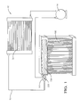
- FIG. 1 Shown in Fig. 1 is schematic illustration of an air conditioning system 10 having a closed refrigerant loop 12 hydraulically connecting a compressor 14, a condenser 16, and an evaporator 100 in series.
- the evaporator 100 includes a hybrid expansion device (HED) 200 configured to provide uniform refrigerant aliquoting through the evaporator 100 for all operating refrigerant flow velocities caused by variations in the compressor 14 speed.
- the HED 200 includes a first stage refrigerant pressure drop device 202, such as a Thermostatic Expansion Valve (TXV) 202, and a second stage refrigerant pressure drop device 204, such as an enhanced orifice tube (EOT) 204.
- TXV Thermostatic Expansion Valve
- EOT enhanced orifice tube
- the evaporator 100 includes an inlet manifold 102, an outlet manifold 104, and plurality of refrigerant tubes 106 hydraulically connecting the manifolds 102, 104 for refrigerant flow from the inlet manifold 102 to the outlet manifold 104.
- Each of the refrigerant tubes 106 defines a U-shaped path for refrigerant flow therebetween, thereby enabling the inlet manifold 102 and outlet manifold 104 to be placed in a side-by-side parallel arrangement.
- the evaporator 100 may also include a return manifold 105 in hydraulic connection with and spaced from inlet and outlet manifolds 102, 104.
- the inlet open ends 107 of the refrigerant tubes 106 are inserted through tube slots 109 positioned along the inlet manifold 102 for refrigerant flow from the inlet manifold 102 to the refrigerant tubes 106.
- the inlet manifold 102 and outlet manifold 104 are shown above the refrigerant tubes 106 with respect to the direction of gravity.
- a plurality of fins 108 is disposed between the refrigerant tubes 106 to facilitate heat exchange between the refrigerant and a stream of ambient air.
- the refrigerant tubes 106 and fins 108 are formed of a heat conductive material, preferably an aluminum alloy, assembled onto the manifolds 102, 104 and brazed into an evaporator heat exchanger assembly.
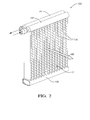
- FIG. 3 Shown in Fig. 3 is a cross-sectional view of the inlet manifold 102 of the evaporator 100 extending along a manifold axis A.
- the inlet manifold 102 includes an inlet port 110 for receiving the second stage refrigerant pressure drop device 204, which is configured to cooperate with the upstream first stage refrigerant pressure drop device 202 to improve refrigerant aliquoting across refrigerant tubes 106 of the evaporator 100.
- the first stage refrigerant pressure drop device 202 expands a liquid refrigerant from the condenser into a first mixture of two phase refrigerant and the second stage refrigerant pressure drop device 204 expands the first mixture into a second mixture of two phase refrigerant.
- the second stage refrigerant pressure drop device 204 may be that of an EOT 204 disposed within the interior chamber 103 defined by the inlet manifold 102, extending substantially the length of the interior chamber 103 and substantially parallel with the manifold axis A.
- the EOT 204 includes an inlet end 214, a blind distal end 216 opposite that of the inlet end 214, and a plurality of orifices 206 therebetween.
- the inlet end 214 is in direct hydraulic connection with the upstream first stage refrigerant pressure drop device 202.
- the blind distal end 216 is typically mounted by capturing it in the end cap 117 of the inlet manifold 102.
- the plurality of orifices 206 may be arranged in a linear array parallel to the manifold axis A and oriented away from the inlet open ends 107 of the refrigerant tubes 106, preferably 180 degrees from the inlet open ends 107 and in the opposite direction of gravity.
- the in-vehicle position is such that the manifolds 102, 104 are at the top, the return manifold 105 is at the bottom, and the evaporator face 112 is substantially perpendicular to the ground.
- the orifices 206 of the EOT 204 are substantially opposite to the gravity direction.
- the first stage refrigerant pressure drop device 202 shown in Fig. 1 may be that of a low pressure drop TXV (LP-TXV) 202, configured to operate at a pressure drop lower than that of the pressure drop of a conventional TXV for a conditioning system without an orifice tube.
- the HED 200 provides a two stage total pressure drop, in which the total pressure drop is apportioned between the LP-TXV 202 and the EOT 204 and is equivalent to the pressure drop of a conventional TXV. It was surprisingly found that a controlled two stage pressure drop provided by the LP-TXV and EOT working in unison, resulted in the improved aliquoting of refrigerant through the refrigerant tubes 106 of the evaporator 100.
- the LP-TXV 202 is configured to provide a first mixture of two phase refrigerant to the EOT204.
- the EOT 204 serves as a retention and expansion device where it retains and accumulates the first mixture of two phase refrigerant until the liquid part of the incoming mixture substantially fills the interior volume of the EOT 204 before being discharged through the orifices 206 as a second mixture of two phase refrigerant, thereby aliquoting the refrigerant across the refrigerant tubes 106.
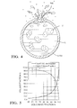
- the first mixture of two phase refrigerant has a liquid mass fraction of 75% and a corresponding liquid volume fraction of only 8.9%.
- Fig. 5 is a chart and graph, respectively, showing the liquid mass fraction of a refrigerant and the corresponding liquid volume and vapor volume fractions for refrigerant R134a at a typical evaporator inlet pressure and temperature.
- This high proportion of liquid ensures that liquid particles eject out of each of the orifices, thereby disrupting the sound pressure waves generated in the vapor; therefore, this prevents the hiss noise generation. Also this high proportion of liquid ensures aliquoting process will be achieved. So the idea here is to have an internal diameter of the EOT 204 such that that after the first stage mixture comes in, it is further mixed with the sitting liquid, rendering the inside-EOT liquid mass fraction to significantly increase. However, the EOT diameter should not be so large as to cause the separation of vapor from liquid; in other words, the mixture should stay as a mixture even after combining with the sitting liquid inside the EOT.
- a substantially high liquid volume fraction refrigerant is desirable in the EOT 204 because a liquid refrigerant is easier to aliquot amongst the refrigerant tubes 106 than refrigerant with a substantially high vapor volume fraction.
- the LP-TXV be configured to provide a first stage pressure drop such that the first mixture of two phase refrigerant exiting the LP-TXV 202 into the EOT 204 is approximately 75-85% by mass in the liquid phase (L) having vapor bubbles (V) dispersed in the liquid phase (L).
- the EOT 204 be configured by varying the diameter, orifice size, and orifice spacing to provide a second stage pressure drop such that the second mixture of two phase refrigerant flowing out of the orifices 206 the EOT 204 into the manifold 100 is approximately 65-75% by mass in the liquid phase. It is also preferred that the diameter, orifice size, and orifice spacing of the EOT 204 be sized to retain a liquid phase of refrigerant that occupies at least 99% of the cross-sectional area of the EOT 204.
- the length and internal diameter of the EOT 204 determines the resistance to axial flow of refrigerant and has a pressure drop associated with it.
- the design of the orifice array defined by the number and diameter of orifices, also determines a pressure drop associated with it.
- the pressure drop of the flow from the inlet end 214 to the distal end 216 inside the EOT 204 in the axial direction should be approximately 5% to 10% of the total pressure drop across EOT 204 for effective control at all flow velocities.
- each orifice 206 and a segment of the EOT between it and the upstream orifice functions as a short orifice tube.
- the EOT 204 can be considered as a series of multiple short orifice tubes connected end to end. This is how the EOT 204 differs from a conventional monolithic orifice tube which handles the total flow through it. By apportioning the total refrigerant flow equally to these short orifice tubes, uniform refrigerant aliquoting is achieved.
- the preferred range of the internal diameter of the EOT is such that it should be large enough to prevent resistance to refrigerant flow where less than the allocated amount of the refrigerant is able to flow to the distal end 216 of the EOT, but, small enough to prevent the incoming first mixture of two phase refrigerant flow from separating into liquid and vapor strata.
- the preferred orientation of the array of orifices is such that the orifices are oriented upward, away from the direction of gravity. It is preferable to orient the array of orifices 206 substantially upward and not sideways or downward with respect to the direction of gravity. If the orifices 206 are oriented substantially downward, the liquid phase refrigerant may drain out of the orifices 206 under the force of gravity soon after entering the EOT 204 and the orifices 206 nearest the inlet port 110 will be disproportionately favored by the liquid refrigerant leaving only a trickle of the liquid flowing to the last few orifices farthest from the inlet port 110. This is especially true at low refrigerant flow conditions.
- the total pressure drop in the EOT 204 results in the lowering of the inlet quality of refrigerant, meaning the mass proportion of the liquid to vapor is increased, thereby, helping the distribution inside the EOT. Without the EOT 204, the mass proportion of the liquid to vapor phase entering the evaporator 100 will be lower, giving rise to poor distribution of refrigerant across the refrigerant tubes 106. Besides being an aliquoting mechanism, the EOT 204 is thus a throttling mechanism, but the throttling is happening in multiple stages spread out across the length of the EOT above the refrigerant tubes 106. Thus the refrigerant tubes 106 are receiving aliquoted flow compared to the situation when EOT is absent and the TXV is the sole throttling device present upstream of the inlet of the evaporator.
- a benefit of the evaporator 100 having an HED 200 is that the evaporator having an HED achieves 17% energy reduction as compared to an evaporator having only a conventional orifice tube. Compared to the evaporator having only a TXV, the evaporator 100 having an HED 200 provides a noise-free, uniform temperature distribution, and is responsive to sudden transient refrigerant flows corresponding to varying engine rpm.
- Another benefit of evaporator 100 having an HED 200 is that it eliminates the need for an Accumulator/Dehydrator (A/D) in the downstream side of the evaporator, which is needed for conventional orifice tube systems and which adds pressure drop and reduces the performance of the air-conditioning system. Every 1 psi of pressure drop in the downstream side of the evaporator results in an increase in air outlet temperature by almost 0.75°F. The A/D traditionally adds about 3 psi pressure drop at high flows.
- A/D Accumulator/Dehydrator
Landscapes
- Engineering & Computer Science (AREA)
- Physics & Mathematics (AREA)
- Mechanical Engineering (AREA)
- Thermal Sciences (AREA)
- General Engineering & Computer Science (AREA)
- Heat-Exchange Devices With Radiators And Conduit Assemblies (AREA)
Applications Claiming Priority (1)
| Application Number | Priority Date | Filing Date | Title |
|---|---|---|---|
| US14/069,878 US9568225B2 (en) | 2013-11-01 | 2013-11-01 | Evaporator having a hybrid expansion device for improved aliquoting of refrigerant |
Publications (2)
| Publication Number | Publication Date |
|---|---|
| EP2869018A1 true EP2869018A1 (de) | 2015-05-06 |
| EP2869018B1 EP2869018B1 (de) | 2020-03-18 |
Family
ID=51703074
Family Applications (1)
| Application Number | Title | Priority Date | Filing Date |
|---|---|---|---|
| EP14189144.0A Active EP2869018B1 (de) | 2013-11-01 | 2014-10-16 | Verdampfer mit einer hybriden Expansionsvorrichtung für verbessertes Aufteilen von Kältemittel |
Country Status (4)
| Country | Link |
|---|---|
| US (1) | US9568225B2 (de) |
| EP (1) | EP2869018B1 (de) |
| KR (1) | KR20150051136A (de) |
| CN (2) | CN104613680B (de) |
Cited By (3)
| Publication number | Priority date | Publication date | Assignee | Title |
|---|---|---|---|---|
| EP2990752A1 (de) * | 2014-08-26 | 2016-03-02 | Delphi Technologies, Inc. | Zweiflutiger verdampfer |
| FR3075346A1 (fr) * | 2017-12-19 | 2019-06-21 | Valeo Systemes Thermiques | Boite collectrice d'un echangeur thermique munie d'un organe de maintien et/ou de positionnement angulaire d'un dispositif de distribution d'un fluide refrigerant |
| FR3097947A1 (fr) * | 2019-06-30 | 2021-01-01 | Valeo Systemes Thermiques | Installation de conditionnement d’air comprenant un échangeur thermique parcouru par un fluide réfrigérant |
Families Citing this family (15)
| Publication number | Priority date | Publication date | Assignee | Title |
|---|---|---|---|---|
| US9568225B2 (en) * | 2013-11-01 | 2017-02-14 | Mahle International Gmbh | Evaporator having a hybrid expansion device for improved aliquoting of refrigerant |
| CN104048548B (zh) * | 2014-05-26 | 2016-01-27 | 杭州三花微通道换热器有限公司 | 可调节的制冷剂分配装置和具有它的换热器 |
| DE102015215253A1 (de) * | 2015-08-11 | 2017-02-16 | Bayerische Motoren Werke Aktiengesellschaft | Kühlvorrichtung für Energiespeicher |
| FR3061284B1 (fr) | 2016-11-30 | 2019-10-18 | Valeo Systemes Thermiques | Echangeur de chaleur constitutif d'un circuit de fluide refrigerant |
| FR3059395B1 (fr) | 2016-11-30 | 2020-09-25 | Valeo Systemes Thermiques | Dispositif d’homogeneisation de la distribution d’un fluide refrigerant a l’interieur de tubes d’un echangeur de chaleur constitutif d’un circuit de fluide refrigerant |
| EP3548824B1 (de) | 2016-11-30 | 2023-03-29 | Valeo Systemes Thermiques | Vorrichtung zur homogenisierung der verteilung eines kältemittels im innern von rohren eines einen kältemittelkreislauf bildenden wärmetauschers |
| FR3059397B1 (fr) | 2016-11-30 | 2019-07-26 | Valeo Systemes Thermiques | Dispositif de distribution d’un fluide refrigerant a l’interieur de tubes d’un echangeur de chaleur constitutif d’un circuit de fluide refrigerant |
| FR3059410B1 (fr) * | 2016-11-30 | 2019-07-19 | Valeo Systemes Thermiques | Organe de mixage constitutif d'un dispositif d'homogeneisation de la distribution d'un fluide refrigerant a l'interieur de tubes d'un echangeur de chaleur |
| FR3061950B1 (fr) | 2016-11-30 | 2020-02-14 | Valeo Systemes Thermiques | Dispositif d’homogeneisation de la distribution d’un fluide refrigerant a l’interieur de tubes d’un echangeur de chaleur constitutif d’un circuit de fluide refrigerant |
| FR3066262B1 (fr) | 2017-05-10 | 2019-11-22 | Valeo Systemes Thermiques | Echangeur de chaleur constitutif d'un circuit de fluide refrigerant |
| DE102017211529A1 (de) * | 2017-07-06 | 2019-01-10 | Mahle International Gmbh | Einsatzrohr für den Eintrittskanal eines Plattenwärmetauschers |
| KR102695168B1 (ko) * | 2018-06-21 | 2024-08-14 | 한온시스템 주식회사 | 열교환기 |
| KR102575777B1 (ko) | 2018-08-13 | 2023-09-08 | 삼성전자주식회사 | 공기조화기 |
| US11946676B2 (en) | 2022-04-01 | 2024-04-02 | Goodman Manufacturing Company, L.P. | Fixed orifice refrigerant distribution system |
| US20250067527A1 (en) * | 2023-08-23 | 2025-02-27 | Hanon Systems | Heat exchanger inlet and outlet pipe connection structure |
Citations (4)
| Publication number | Priority date | Publication date | Assignee | Title |
|---|---|---|---|---|
| WO1994014021A1 (en) * | 1992-12-07 | 1994-06-23 | Multistack International Limited | Improvements in plate heat-exchangers |
| US5806586A (en) * | 1993-07-03 | 1998-09-15 | Ernst Flitsch Gmbh & Co. | Plate heat exchanger with a refrigerant distributor |
| DE19719251A1 (de) * | 1997-05-07 | 1998-11-12 | Valeo Klimatech Gmbh & Co Kg | Verteil-/Sammel-Kasten eines mindestens zweiflutigen Verdampfers einer Kraftfahrzeugklimaanlage |
| WO2006083426A1 (en) * | 2005-02-02 | 2006-08-10 | Carrier Corporation | Tube inset and bi-flow arrangement for a header of a heat pump |
Family Cites Families (23)
| Publication number | Priority date | Publication date | Assignee | Title |
|---|---|---|---|---|
| US1684083A (en) | 1927-06-02 | 1928-09-11 | Samuel C Bloom | Refrigerating coil |
| US3976128A (en) | 1975-06-12 | 1976-08-24 | Ford Motor Company | Plate and fin heat exchanger |
| JPH02217764A (ja) | 1989-02-17 | 1990-08-30 | Matsushita Electric Ind Co Ltd | 膨張弁 |
| JP2936775B2 (ja) | 1991-04-05 | 1999-08-23 | 株式会社デンソー | 熱交換器 |
| JPH08189725A (ja) | 1995-01-05 | 1996-07-23 | Nippondenso Co Ltd | 冷媒蒸発器 |
| IT1276990B1 (it) | 1995-10-24 | 1997-11-03 | Tetra Laval Holdings & Finance | Scambiatore di calore a piastre |
| JP3705859B2 (ja) | 1996-03-29 | 2005-10-12 | サンデン株式会社 | 分配装置を備えた熱交換器 |
| DE19719252C2 (de) | 1997-05-07 | 2002-10-31 | Valeo Klimatech Gmbh & Co Kg | Zweiflutiger und in Luftrichtung einreihiger hartverlöteter Flachrohrverdampfer für eine Kraftfahrzeugklimaanlage |
| JP4568973B2 (ja) | 2000-08-10 | 2010-10-27 | ダイキン工業株式会社 | プレート型熱交換器 |
| US6729386B1 (en) * | 2001-01-22 | 2004-05-04 | Stanley H. Sather | Pulp drier coil with improved header |
| US20030116310A1 (en) | 2001-12-21 | 2003-06-26 | Wittmann Joseph E. | Flat tube heat exchanger core with internal fluid supply and suction lines |
| US6814136B2 (en) | 2002-08-06 | 2004-11-09 | Visteon Global Technologies, Inc. | Perforated tube flow distributor |
| EP1548380A3 (de) | 2003-12-22 | 2006-10-04 | Hussmann Corporation | Flachrohrverdampfer mit Mikroverteiler |
| US7331195B2 (en) * | 2004-10-01 | 2008-02-19 | Advanced Heat Transfer Llc | Refrigerant distribution device and method |
| US7086249B2 (en) * | 2004-10-01 | 2006-08-08 | Advanced Heat Transfer, Llc | Refrigerant distribution device and method |
| US8171987B2 (en) | 2006-11-13 | 2012-05-08 | Carrier Corporation | Minichannel heat exchanger header insert for distribution |
| JP2009075772A (ja) | 2007-09-19 | 2009-04-09 | Fuji Xerox Co Ltd | 印刷指示装置、印刷装置、印刷システム、及びプログラム |
| US8607852B2 (en) * | 2007-11-14 | 2013-12-17 | Swep International Ab | Distribution pipe |
| US20090173482A1 (en) | 2008-01-09 | 2009-07-09 | Beamer Henry E | Distributor tube subassembly |
| US20090229805A1 (en) | 2008-03-13 | 2009-09-17 | Delphi Technologies, Inc. | Manifold design having an improved collector conduit and method of making same |
| CN102027308A (zh) * | 2008-05-16 | 2011-04-20 | 开利公司 | 具有增强的制冷剂分布的微通道热交换器 |
| US20110290465A1 (en) * | 2010-06-01 | 2011-12-01 | Delphi Technologies, Inc. | Orientation insensitive refrigerant distributor tube |
| US9568225B2 (en) * | 2013-11-01 | 2017-02-14 | Mahle International Gmbh | Evaporator having a hybrid expansion device for improved aliquoting of refrigerant |
-
2013
- 2013-11-01 US US14/069,878 patent/US9568225B2/en not_active Expired - Fee Related
-
2014
- 2014-08-12 CN CN201410395055.7A patent/CN104613680B/zh not_active Expired - Fee Related
- 2014-08-12 CN CN201420453550.4U patent/CN204154032U/zh not_active Expired - Fee Related
- 2014-09-01 KR KR1020140115206A patent/KR20150051136A/ko not_active Ceased
- 2014-10-16 EP EP14189144.0A patent/EP2869018B1/de active Active
Patent Citations (4)
| Publication number | Priority date | Publication date | Assignee | Title |
|---|---|---|---|---|
| WO1994014021A1 (en) * | 1992-12-07 | 1994-06-23 | Multistack International Limited | Improvements in plate heat-exchangers |
| US5806586A (en) * | 1993-07-03 | 1998-09-15 | Ernst Flitsch Gmbh & Co. | Plate heat exchanger with a refrigerant distributor |
| DE19719251A1 (de) * | 1997-05-07 | 1998-11-12 | Valeo Klimatech Gmbh & Co Kg | Verteil-/Sammel-Kasten eines mindestens zweiflutigen Verdampfers einer Kraftfahrzeugklimaanlage |
| WO2006083426A1 (en) * | 2005-02-02 | 2006-08-10 | Carrier Corporation | Tube inset and bi-flow arrangement for a header of a heat pump |
Cited By (6)
| Publication number | Priority date | Publication date | Assignee | Title |
|---|---|---|---|---|
| EP2990752A1 (de) * | 2014-08-26 | 2016-03-02 | Delphi Technologies, Inc. | Zweiflutiger verdampfer |
| FR3075346A1 (fr) * | 2017-12-19 | 2019-06-21 | Valeo Systemes Thermiques | Boite collectrice d'un echangeur thermique munie d'un organe de maintien et/ou de positionnement angulaire d'un dispositif de distribution d'un fluide refrigerant |
| WO2019121557A1 (en) * | 2017-12-19 | 2019-06-27 | Valeo Systemes Thermiques | Header of a heat exchanger provided with a member for retention and/or angular positioning of a device for distribution of a refrigerant fluid |
| US11774193B2 (en) | 2017-12-19 | 2023-10-03 | Valeo Systemes Thermiques | Header of a heat exchanger provided with a member for retention and/or angular positioning of a device for distribution of a refrigerant fluid |
| FR3097947A1 (fr) * | 2019-06-30 | 2021-01-01 | Valeo Systemes Thermiques | Installation de conditionnement d’air comprenant un échangeur thermique parcouru par un fluide réfrigérant |
| WO2021001622A1 (fr) * | 2019-06-30 | 2021-01-07 | Valeo Systemes Thermiques | Installation de conditionnement d'air comprenant un échangeur thermique parcouru par un fluide réfrigérant |
Also Published As
| Publication number | Publication date |
|---|---|
| CN104613680A (zh) | 2015-05-13 |
| US9568225B2 (en) | 2017-02-14 |
| CN204154032U (zh) | 2015-02-11 |
| CN104613680B (zh) | 2018-03-20 |
| KR20150051136A (ko) | 2015-05-11 |
| US20150121950A1 (en) | 2015-05-07 |
| EP2869018B1 (de) | 2020-03-18 |
Similar Documents
| Publication | Publication Date | Title |
|---|---|---|
| EP2869018B1 (de) | Verdampfer mit einer hybriden Expansionsvorrichtung für verbessertes Aufteilen von Kältemittel | |
| US6427480B1 (en) | Refrigerant cycle system | |
| US7987685B2 (en) | Refrigerant cycle device with ejector | |
| US8099978B2 (en) | Evaporator unit | |
| JP4075530B2 (ja) | 冷凍サイクル | |
| JP4626531B2 (ja) | エジェクタ式冷凍サイクル | |
| US9625214B2 (en) | Heat exchanger | |
| US8534093B2 (en) | Unit for ejector-type refrigeration cycle, and refrigeration cycle device using the same | |
| US20160061497A1 (en) | Two-pass evaporator | |
| US20120216562A1 (en) | Unitary heat pump air conditioner having a heat exchanger with an integral accumulator | |
| US8424338B2 (en) | Vapor compression refrigerating cycle apparatus with an ejector and distributor | |
| EP2629032A2 (de) | Einheitliche Wärmepumpenklimaanlage mit Wärmetauscher mit integriertem Akkumulator | |
| JP4415835B2 (ja) | 車両用冷凍サイクル装置 | |
| US20130333402A1 (en) | Climate control systems for motor vehicles and methods of operating the same | |
| US6880362B2 (en) | Refrigerating cycle apparatus | |
| US9346338B2 (en) | Low refrigerant charge secondary loop air conditioning system | |
| JP2000283577A (ja) | 冷凍装置用冷凍サイクル | |
| JP5062066B2 (ja) | エジェクタ式冷凍サイクル用蒸発器ユニット | |
| US20080127666A1 (en) | Vehicle Heat Exchanger and Cooling System | |
| JPH0526522A (ja) | 冷凍サイクル | |
| JP2007040612A (ja) | 蒸気圧縮式サイクル | |
| JP2016050761A (ja) | エジェクタ式冷凍サイクル | |
| JP6459807B2 (ja) | エジェクタ式冷凍サイクル | |
| JP2012172850A (ja) | 冷媒放熱器 | |
| JP2007032945A (ja) | エジェクタ式サイクルおよびその流量調節弁 |
Legal Events
| Date | Code | Title | Description |
|---|---|---|---|
| PUAI | Public reference made under article 153(3) epc to a published international application that has entered the european phase |
Free format text: ORIGINAL CODE: 0009012 |
|
| 17P | Request for examination filed |
Effective date: 20141016 |
|
| AK | Designated contracting states |
Kind code of ref document: A1 Designated state(s): AL AT BE BG CH CY CZ DE DK EE ES FI FR GB GR HR HU IE IS IT LI LT LU LV MC MK MT NL NO PL PT RO RS SE SI SK SM TR |
|
| AX | Request for extension of the european patent |
Extension state: BA ME |
|
| RAP1 | Party data changed (applicant data changed or rights of an application transferred) |
Owner name: MAHLE INTERNATIONAL GMBH |
|
| R17P | Request for examination filed (corrected) |
Effective date: 20151028 |
|
| RBV | Designated contracting states (corrected) |
Designated state(s): AL AT BE BG CH CY CZ DE DK EE ES FI FR GB GR HR HU IE IS IT LI LT LU LV MC MK MT NL NO PL PT RO RS SE SI SK SM TR |
|
| STAA | Information on the status of an ep patent application or granted ep patent |
Free format text: STATUS: EXAMINATION IS IN PROGRESS |
|
| 17Q | First examination report despatched |
Effective date: 20171027 |
|
| GRAP | Despatch of communication of intention to grant a patent |
Free format text: ORIGINAL CODE: EPIDOSNIGR1 |
|
| STAA | Information on the status of an ep patent application or granted ep patent |
Free format text: STATUS: GRANT OF PATENT IS INTENDED |
|
| INTG | Intention to grant announced |
Effective date: 20191007 |
|
| GRAS | Grant fee paid |
Free format text: ORIGINAL CODE: EPIDOSNIGR3 |
|
| GRAA | (expected) grant |
Free format text: ORIGINAL CODE: 0009210 |
|
| STAA | Information on the status of an ep patent application or granted ep patent |
Free format text: STATUS: THE PATENT HAS BEEN GRANTED |
|
| AK | Designated contracting states |
Kind code of ref document: B1 Designated state(s): AL AT BE BG CH CY CZ DE DK EE ES FI FR GB GR HR HU IE IS IT LI LT LU LV MC MK MT NL NO PL PT RO RS SE SI SK SM TR |
|
| REG | Reference to a national code |
Ref country code: GB Ref legal event code: FG4D |
|
| REG | Reference to a national code |
Ref country code: DE Ref legal event code: R096 Ref document number: 602014062442 Country of ref document: DE |
|
| REG | Reference to a national code |
Ref country code: AT Ref legal event code: REF Ref document number: 1246378 Country of ref document: AT Kind code of ref document: T Effective date: 20200415 Ref country code: IE Ref legal event code: FG4D |
|
| PG25 | Lapsed in a contracting state [announced via postgrant information from national office to epo] |
Ref country code: RS Free format text: LAPSE BECAUSE OF FAILURE TO SUBMIT A TRANSLATION OF THE DESCRIPTION OR TO PAY THE FEE WITHIN THE PRESCRIBED TIME-LIMIT Effective date: 20200318 Ref country code: NO Free format text: LAPSE BECAUSE OF FAILURE TO SUBMIT A TRANSLATION OF THE DESCRIPTION OR TO PAY THE FEE WITHIN THE PRESCRIBED TIME-LIMIT Effective date: 20200618 Ref country code: FI Free format text: LAPSE BECAUSE OF FAILURE TO SUBMIT A TRANSLATION OF THE DESCRIPTION OR TO PAY THE FEE WITHIN THE PRESCRIBED TIME-LIMIT Effective date: 20200318 |
|
| REG | Reference to a national code |
Ref country code: NL Ref legal event code: MP Effective date: 20200318 |
|
| PG25 | Lapsed in a contracting state [announced via postgrant information from national office to epo] |
Ref country code: SE Free format text: LAPSE BECAUSE OF FAILURE TO SUBMIT A TRANSLATION OF THE DESCRIPTION OR TO PAY THE FEE WITHIN THE PRESCRIBED TIME-LIMIT Effective date: 20200318 Ref country code: LV Free format text: LAPSE BECAUSE OF FAILURE TO SUBMIT A TRANSLATION OF THE DESCRIPTION OR TO PAY THE FEE WITHIN THE PRESCRIBED TIME-LIMIT Effective date: 20200318 Ref country code: GR Free format text: LAPSE BECAUSE OF FAILURE TO SUBMIT A TRANSLATION OF THE DESCRIPTION OR TO PAY THE FEE WITHIN THE PRESCRIBED TIME-LIMIT Effective date: 20200619 Ref country code: HR Free format text: LAPSE BECAUSE OF FAILURE TO SUBMIT A TRANSLATION OF THE DESCRIPTION OR TO PAY THE FEE WITHIN THE PRESCRIBED TIME-LIMIT Effective date: 20200318 Ref country code: BG Free format text: LAPSE BECAUSE OF FAILURE TO SUBMIT A TRANSLATION OF THE DESCRIPTION OR TO PAY THE FEE WITHIN THE PRESCRIBED TIME-LIMIT Effective date: 20200618 |
|
| REG | Reference to a national code |
Ref country code: LT Ref legal event code: MG4D |
|
| PG25 | Lapsed in a contracting state [announced via postgrant information from national office to epo] |
Ref country code: NL Free format text: LAPSE BECAUSE OF FAILURE TO SUBMIT A TRANSLATION OF THE DESCRIPTION OR TO PAY THE FEE WITHIN THE PRESCRIBED TIME-LIMIT Effective date: 20200318 |
|
| PG25 | Lapsed in a contracting state [announced via postgrant information from national office to epo] |
Ref country code: IS Free format text: LAPSE BECAUSE OF FAILURE TO SUBMIT A TRANSLATION OF THE DESCRIPTION OR TO PAY THE FEE WITHIN THE PRESCRIBED TIME-LIMIT Effective date: 20200718 Ref country code: SK Free format text: LAPSE BECAUSE OF FAILURE TO SUBMIT A TRANSLATION OF THE DESCRIPTION OR TO PAY THE FEE WITHIN THE PRESCRIBED TIME-LIMIT Effective date: 20200318 Ref country code: RO Free format text: LAPSE BECAUSE OF FAILURE TO SUBMIT A TRANSLATION OF THE DESCRIPTION OR TO PAY THE FEE WITHIN THE PRESCRIBED TIME-LIMIT Effective date: 20200318 Ref country code: SM Free format text: LAPSE BECAUSE OF FAILURE TO SUBMIT A TRANSLATION OF THE DESCRIPTION OR TO PAY THE FEE WITHIN THE PRESCRIBED TIME-LIMIT Effective date: 20200318 Ref country code: EE Free format text: LAPSE BECAUSE OF FAILURE TO SUBMIT A TRANSLATION OF THE DESCRIPTION OR TO PAY THE FEE WITHIN THE PRESCRIBED TIME-LIMIT Effective date: 20200318 Ref country code: CZ Free format text: LAPSE BECAUSE OF FAILURE TO SUBMIT A TRANSLATION OF THE DESCRIPTION OR TO PAY THE FEE WITHIN THE PRESCRIBED TIME-LIMIT Effective date: 20200318 Ref country code: LT Free format text: LAPSE BECAUSE OF FAILURE TO SUBMIT A TRANSLATION OF THE DESCRIPTION OR TO PAY THE FEE WITHIN THE PRESCRIBED TIME-LIMIT Effective date: 20200318 Ref country code: PT Free format text: LAPSE BECAUSE OF FAILURE TO SUBMIT A TRANSLATION OF THE DESCRIPTION OR TO PAY THE FEE WITHIN THE PRESCRIBED TIME-LIMIT Effective date: 20200812 |
|
| REG | Reference to a national code |
Ref country code: AT Ref legal event code: MK05 Ref document number: 1246378 Country of ref document: AT Kind code of ref document: T Effective date: 20200318 |
|
| REG | Reference to a national code |
Ref country code: DE Ref legal event code: R097 Ref document number: 602014062442 Country of ref document: DE |
|
| PLBE | No opposition filed within time limit |
Free format text: ORIGINAL CODE: 0009261 |
|
| STAA | Information on the status of an ep patent application or granted ep patent |
Free format text: STATUS: NO OPPOSITION FILED WITHIN TIME LIMIT |
|
| PG25 | Lapsed in a contracting state [announced via postgrant information from national office to epo] |
Ref country code: ES Free format text: LAPSE BECAUSE OF FAILURE TO SUBMIT A TRANSLATION OF THE DESCRIPTION OR TO PAY THE FEE WITHIN THE PRESCRIBED TIME-LIMIT Effective date: 20200318 Ref country code: AT Free format text: LAPSE BECAUSE OF FAILURE TO SUBMIT A TRANSLATION OF THE DESCRIPTION OR TO PAY THE FEE WITHIN THE PRESCRIBED TIME-LIMIT Effective date: 20200318 Ref country code: IT Free format text: LAPSE BECAUSE OF FAILURE TO SUBMIT A TRANSLATION OF THE DESCRIPTION OR TO PAY THE FEE WITHIN THE PRESCRIBED TIME-LIMIT Effective date: 20200318 Ref country code: DK Free format text: LAPSE BECAUSE OF FAILURE TO SUBMIT A TRANSLATION OF THE DESCRIPTION OR TO PAY THE FEE WITHIN THE PRESCRIBED TIME-LIMIT Effective date: 20200318 |
|
| 26N | No opposition filed |
Effective date: 20201221 |
|
| PG25 | Lapsed in a contracting state [announced via postgrant information from national office to epo] |
Ref country code: PL Free format text: LAPSE BECAUSE OF FAILURE TO SUBMIT A TRANSLATION OF THE DESCRIPTION OR TO PAY THE FEE WITHIN THE PRESCRIBED TIME-LIMIT Effective date: 20200318 |
|
| PG25 | Lapsed in a contracting state [announced via postgrant information from national office to epo] |
Ref country code: SI Free format text: LAPSE BECAUSE OF FAILURE TO SUBMIT A TRANSLATION OF THE DESCRIPTION OR TO PAY THE FEE WITHIN THE PRESCRIBED TIME-LIMIT Effective date: 20200318 |
|
| REG | Reference to a national code |
Ref country code: CH Ref legal event code: PL |
|
| GBPC | Gb: european patent ceased through non-payment of renewal fee |
Effective date: 20201016 |
|
| PG25 | Lapsed in a contracting state [announced via postgrant information from national office to epo] |
Ref country code: LU Free format text: LAPSE BECAUSE OF NON-PAYMENT OF DUE FEES Effective date: 20201016 Ref country code: MC Free format text: LAPSE BECAUSE OF FAILURE TO SUBMIT A TRANSLATION OF THE DESCRIPTION OR TO PAY THE FEE WITHIN THE PRESCRIBED TIME-LIMIT Effective date: 20200318 |
|
| REG | Reference to a national code |
Ref country code: BE Ref legal event code: MM Effective date: 20201031 |
|
| PG25 | Lapsed in a contracting state [announced via postgrant information from national office to epo] |
Ref country code: FR Free format text: LAPSE BECAUSE OF NON-PAYMENT OF DUE FEES Effective date: 20201031 |
|
| PG25 | Lapsed in a contracting state [announced via postgrant information from national office to epo] |
Ref country code: GB Free format text: LAPSE BECAUSE OF NON-PAYMENT OF DUE FEES Effective date: 20201016 Ref country code: LI Free format text: LAPSE BECAUSE OF NON-PAYMENT OF DUE FEES Effective date: 20201031 Ref country code: BE Free format text: LAPSE BECAUSE OF NON-PAYMENT OF DUE FEES Effective date: 20201031 Ref country code: CH Free format text: LAPSE BECAUSE OF NON-PAYMENT OF DUE FEES Effective date: 20201031 |
|
| PG25 | Lapsed in a contracting state [announced via postgrant information from national office to epo] |
Ref country code: IE Free format text: LAPSE BECAUSE OF NON-PAYMENT OF DUE FEES Effective date: 20201016 |
|
| PGFP | Annual fee paid to national office [announced via postgrant information from national office to epo] |
Ref country code: DE Payment date: 20211027 Year of fee payment: 8 |
|
| PG25 | Lapsed in a contracting state [announced via postgrant information from national office to epo] |
Ref country code: TR Free format text: LAPSE BECAUSE OF FAILURE TO SUBMIT A TRANSLATION OF THE DESCRIPTION OR TO PAY THE FEE WITHIN THE PRESCRIBED TIME-LIMIT Effective date: 20200318 Ref country code: MT Free format text: LAPSE BECAUSE OF FAILURE TO SUBMIT A TRANSLATION OF THE DESCRIPTION OR TO PAY THE FEE WITHIN THE PRESCRIBED TIME-LIMIT Effective date: 20200318 Ref country code: CY Free format text: LAPSE BECAUSE OF FAILURE TO SUBMIT A TRANSLATION OF THE DESCRIPTION OR TO PAY THE FEE WITHIN THE PRESCRIBED TIME-LIMIT Effective date: 20200318 |
|
| PG25 | Lapsed in a contracting state [announced via postgrant information from national office to epo] |
Ref country code: MK Free format text: LAPSE BECAUSE OF FAILURE TO SUBMIT A TRANSLATION OF THE DESCRIPTION OR TO PAY THE FEE WITHIN THE PRESCRIBED TIME-LIMIT Effective date: 20200318 Ref country code: AL Free format text: LAPSE BECAUSE OF FAILURE TO SUBMIT A TRANSLATION OF THE DESCRIPTION OR TO PAY THE FEE WITHIN THE PRESCRIBED TIME-LIMIT Effective date: 20200318 |
|
| REG | Reference to a national code |
Ref country code: DE Ref legal event code: R119 Ref document number: 602014062442 Country of ref document: DE |
|
| PG25 | Lapsed in a contracting state [announced via postgrant information from national office to epo] |
Ref country code: DE Free format text: LAPSE BECAUSE OF NON-PAYMENT OF DUE FEES Effective date: 20230503 |