EP2873493A2 - Winkelschleifer mit einem bürstenlosen Elektromotor - Google Patents
Winkelschleifer mit einem bürstenlosen Elektromotor Download PDFInfo
- Publication number
- EP2873493A2 EP2873493A2 EP20140188196 EP14188196A EP2873493A2 EP 2873493 A2 EP2873493 A2 EP 2873493A2 EP 20140188196 EP20140188196 EP 20140188196 EP 14188196 A EP14188196 A EP 14188196A EP 2873493 A2 EP2873493 A2 EP 2873493A2
- Authority
- EP
- European Patent Office
- Prior art keywords
- rectifier
- power
- electric motor
- handheld
- circuit board
- Prior art date
- Legal status (The legal status is an assumption and is not a legal conclusion. Google has not performed a legal analysis and makes no representation as to the accuracy of the status listed.)
- Granted
Links
Images


Classifications
-
- B—PERFORMING OPERATIONS; TRANSPORTING
- B24—GRINDING; POLISHING
- B24B—MACHINES, DEVICES, OR PROCESSES FOR GRINDING OR POLISHING; DRESSING OR CONDITIONING OF ABRADING SURFACES; FEEDING OF GRINDING, POLISHING, OR LAPPING AGENTS
- B24B47/00—Drives or gearings; Equipment therefor
- B24B47/10—Drives or gearings; Equipment therefor for rotating or reciprocating working-spindles carrying grinding wheels or workpieces
- B24B47/12—Drives or gearings; Equipment therefor for rotating or reciprocating working-spindles carrying grinding wheels or workpieces by mechanical gearing or electric power
-
- B—PERFORMING OPERATIONS; TRANSPORTING
- B24—GRINDING; POLISHING
- B24B—MACHINES, DEVICES, OR PROCESSES FOR GRINDING OR POLISHING; DRESSING OR CONDITIONING OF ABRADING SURFACES; FEEDING OF GRINDING, POLISHING, OR LAPPING AGENTS
- B24B23/00—Portable grinding machines, e.g. hand-guided; Accessories therefor
- B24B23/02—Portable grinding machines, e.g. hand-guided; Accessories therefor with rotating grinding tools; Accessories therefor
- B24B23/028—Angle tools
-
- B—PERFORMING OPERATIONS; TRANSPORTING
- B25—HAND TOOLS; PORTABLE POWER-DRIVEN TOOLS; MANIPULATORS
- B25F—COMBINATION OR MULTI-PURPOSE TOOLS NOT OTHERWISE PROVIDED FOR; DETAILS OR COMPONENTS OF PORTABLE POWER-DRIVEN TOOLS NOT PARTICULARLY RELATED TO THE OPERATIONS PERFORMED AND NOT OTHERWISE PROVIDED FOR
- B25F5/00—Details or components of portable power-driven tools not particularly related to the operations performed and not otherwise provided for
- B25F5/008—Cooling means
-
- H—ELECTRICITY
- H02—GENERATION; CONVERSION OR DISTRIBUTION OF ELECTRIC POWER
- H02K—DYNAMO-ELECTRIC MACHINES
- H02K7/00—Arrangements for handling mechanical energy structurally associated with dynamo-electric machines, e.g. structural association with mechanical driving motors or auxiliary dynamo-electric machines
- H02K7/14—Structural association with mechanical loads, e.g. with hand-held machine tools or fans
- H02K7/145—Hand-held machine tool
Definitions
- the present disclosure relates generally to handheld power tools and more specifically to a handheld grinder with a brushless electric motor.
- Some power tools include brushless electric motors. Power tools with brushless electric motors use a rectifier to convert an alternating current (AC) input into a direct current (DC) that is used to drive the brushless electric motor. Power tools with brushless electric motors also employ a capacitor to lessen ripple and to provide a current when the AC input voltage is unable to do so. Most power tools also include a power switch that directly controls the flow of current through the brushless electric motor. The capacitor and the power switch generate undesirable heat.
- Most power tools include several circuit boards that reside inside a housing of the power tool.
- the circuit boards are used to support the capacitor, the power switch and circuitry that is used for controlling the brushless motor.
- the circuit boards undesirably increase the volume of the power tool.
- the connections between the circuit boards are susceptible to wearing out or breaking. This makes the power tool less reliable. Therefore, there is a need for a power tool that has a smaller volume, generates less heat and is more reliable.
- the handheld grinder comprises an elongated housing having a grip portion that is shaped to be grasped by a user; a grinding disk; an electric motor having a drive shaft; an output shaft having a one end connected to the grinding disk and an opposing end drivably connected to the drive shaft of the motor to impart rotary motion thereto; and a circuit board residing in the housing, the circuit board having thereon a rectifier configured to receive power from an alternating current (AC) power source and operable to convert an alternating current to a direct current, a switching arrangement having a plurality of motor switches connected electrically between the rectifier and the electric motor and operates to deliver the direct current from the rectifier to the electric motor, a capacitor connected electrically between the rectifier and the switching arrangement, wherein the capacitor is coupled in parallel across the rectifier, a driver circuit interfaced with the motor switches and operable to control switching operation of the motor switches, and a power switch connected electrically between the rectifier and the driver circuit and operable by a tool operator to selectively energize
- AC alternating
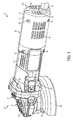
- FIG. 1 depicts an example power tool 10.
- the power tool 10 comprises a housing 12 having an elongated shape.
- a user can grasp the power tool 10 by placing the palm of the user's hand over and around the housing 12.
- An output member 18 is positioned at one end 12-1 of the housing 12 and comprises a right angle gearset 20 that drives a rotating disk 22.
- the rotating disk 22 comprises a grinder disk.
- the rotating disk 22 may be removed and replaced with a new rotating disk.
- a user of the power tool 10 may replace the existing rotating disk 22 with a new rotating disk after the existing rotating disk 22 wears out.
- An adjustable guard 24 may cover at least a portion of the rotating disk 22 to obstruct sparks and debris generated during operation of the power tool 10.
- the power tool 10 may include a chuck that is configured to receive a drill bit or a screw driver bit, thereby allowing the power tool 10 to be used as a power drill or a power screw driver.
- the output member 18 may be removed and replaced with another output member that may be more suitable for a drill, a screw driver, or any other power tool.
- the housing 12 has a first portion 14 and a second portion 16.
- the first portion 14 and second portion 16 may be secured together with screws 26, illustratively six, and enclose an electric motor 28 and electronic circuit components, as further described below, that drive the output member 18. While the present description is provided with reference to a brushless electric motor, the electric motor 28 may be any type of electrical motor capable of driving the output member 18.
- a power cord 30 is connectable to an AC power source and is positioned at an opposite end 12-2 of the housing 12. The power cord 30 provides power to the electric motor 28 and the electronic circuit components of the power tool 10.
- the first portion 14 further includes a power on/off switch 32 and a spindle lock switch 34. Putting the power on/off switch 32 in on and off positions turns on and turns off the electric motor 28, respectively. Pressing and holding the spindle lock switch 34 enables the user to change the rotating disk 22.
- a plurality of narrow slot openings 36 of the first 14 and second 16 portions allow for venting of the electric motor 28 and the electronic circuit components.
- the one end 12-1 of the housing 12 also includes a threaded opening 38 for selectively attaching a side-handle (not shown) to enable two-handed operation.
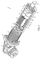
- FIG. 2 depicts a cross sectional view of the power tool 10 with the first portion 14 of the housing 12 removed.
- the power tool 10 includes a circuit board 40 that resides inside the housing 12.
- the circuit board 40 is fastened to the second portion 16 of the housing 12 with screws 42.
- Other fasteners are also contemplated, for example bolts, clips, ties, latches, pegs, snap fasteners, or the like.
- the circuit board 40 has a longitudinal axis that is aligned with the longitudinal axis of the housing 12.
- the circuit board 40 is rectangular.
- other shapes of the circuit board 40 are also contemplated.
- the circuit board 40 may be a square.
- the circuit board 40 may be circular and the circuit board 40 may be positioned such that a planar surface of the circuit board 40 is perpendicular to the longitudinal axis of the housing 12.
- a plurality of electronic circuit components of the power tool 10 are attached to the circuit board 40 and are configured to control the electric motor 28.
- the electronic circuit components may be attached to the circuit board 40 by soldering the electronic circuit components on the circuit board 40.
- the circuit board 40 includes a rectifier 44.
- the rectifier 44 receives an alternating current and converts the alternating current into a direct current.
- the rectifier 44 may be a commercially-available full-wave bridge rectifier.
- the circuit board 40 includes AC input solder points 48.
- the AC input solder points 48 are soldered at an end of the circuit board 40 that is proximate to the end 12-2 of the housing 12. Wires can be connected from the power cord 30 to the AC input solder points 48 to deliver the alternating current to the rectifier 44.
- the circuit board 40 may include a heat sink 46 for diffusing heat away from the rectifier 44.
- the heat sink 46 is placed adjacent to the rectifier 44 and is abutting the rectifier 44.
- DC bus capacitors 50 are soldered adjacent to the rectifier 44. In this embodiment, there are two DC bus capacitors 50, each having a capacitance of about 10 ⁇ F. In an alternate embodiment, the DC bus capacitors 50 may include just one 20 ⁇ F capacitor instead of two 10 ⁇ F capacitors. Other configurations of the DC bus capacitors 50 are also contemplated, for example the number of DC bus capacitors 50 may be three, four, six, eight, etc. In this embodiment, each DC bus capacitor 50 has a longitudinal axis that is perpendicular to the longitudinal axis of the housing 12. In another embodiment, the longitudinal axes of the DC bus capacitors 50 may be aligned with the longitudinal axis of the housing 12.
- the DC bus capacitors 50 are robust capacitors and not traditional electrolytic smoothening capacitors.
- the DC bus capacitors 50 have smaller physical dimensions than traditional electrolytic smoothening capacitors that typically have a capacitance of over 100 ⁇ F.
- the DC bus capacitors 50 generate less heat than typical smoothening capacitors that are 100 ⁇ F or greater.
- the DC bus capacitors 50 are film capacitors.
- the film capacitors can be made from polymer plastics metalized on both sides and may be rolled with additional suitable insulators.
- the smaller physical dimensions and the smaller footprint of the DC bus capacitors 50 in comparison to traditional smoothening capacitors that are greater than 100 ⁇ F, allows placement of the DC bus capacitors 50 onto the circuit board 40 instead of a separate circuit board or placement within housing 12 as disjoint components connected to other components or circuit boards by means of wiring connections.
- the circuit board 40 includes an integrated power module (IPM) 52.
- the IPM 52 is soldered adjacent to the DC bus capacitors 50.
- the IPM 52 includes a switching arrangement that has a plurality of motor switches, a driver circuit and a driver power supply.
- the motor switches may be connected electrically between the rectifier 44 and the electric motor 28.
- the motor switches selectively deliver direct current from the rectifier 44 to electromagnets of the electric motor 28.
- the driver circuit controls the state of the motor switches, for example between an 'on' state and an 'off' state.
- the driver power supply supplies power to the driver circuit.
- the circuit board 40 may include a heat sink 54 that may be positioned on top of the IPM 52. In this embodiment, the heat sink 54 is abutting a top surface of the IPM 52. Additional or alternative cooling mechanisms are also contemplated for cooling the IPM 52. For example, a fan may be mounted on the circuit board 40 to cool the IPM 52.
- the circuit board 40 includes a power switch for selectively turning the power tool 10 on and off.
- the power switch is shown as a switch contact 56 of the power on/off switch 32.
- the switch contact 56 is soldered on the circuit board 40.
- the switch contact 56 is positioned at an end of the circuit board 40 that is proximate to the electric motor 28. Other positions are also contemplated.
- the switch contact 56 may be interposed between the IPM 52 and the DC bus capacitors 50.
- the switch contact 56 may be a mechanical switch that is mechanically coupled with the power on/off switch 32.
- Example mechanical switches include a toggle switch, a rocker switch, a push-button switch, or the like.
- the switch contact 56 may be an electronic switch that is connected to the power on/off switch 32 with a wire. Examples of electronic switches include a relay, a transistor, or the like.
- the switch contact 56 changes states when a user of the power tool 10 changes a position of the power on/off switch 32. For example, if the power on/off switch 32 is moved to an 'on' position then the switch contact 56 moves to a corresponding 'on' state to power on the power tool 10. Similarly, if the power on/off switch 32 is moved to an 'off' position then the switch contact 56 moves to a corresponding 'off' state to power down the power tool 10.
- the switch contact 56 operates at a voltage that is lower than the voltage at which the electric motor 28 operates.
- the switch contact 56 also operates at a current that is lower than the current at which the electric motor 28 operates.
- the electric motor 28 typically draws a current that is higher than one ampere (1 A) and can reach up to 15 A, whereas the current passing through the switch contact 56 is less than 1 A (e.g. 200 mA).
- the switch contact 56 is physically smaller than a switch that operates at the same voltage and current levels as the electric motor 28.
- the switch contact 56 also generates less heat than a switch that operates at the same voltage and current levels as the electric motor 28.
- the smaller physical dimensions and smaller footprint allow placement of the switch contact 56 on the circuit board 40.
- the switch contact 56 operated at the same voltage and current levels as the electric motor 28, then the switch contact 56 might have greater physical dimensions and might generate more heat. Greater physical dimensions and larger heat generation may have required the switch contact 56 to be placed on a separate circuit board or placement within housing 12 as a disjoint component connected to other components or circuit boards by means of wiring connections. Using a separate circuit board for the switch contact 56 would increase the number of inter-board connections and may reduce the reliability of the power tool 10 by making the power tool 10 susceptible to more connection breakages. Using an additional circuit board for the switch contact 56 may undesirably increase the size of the power tool 10.
- the circuit board 40 may include motor connections 58.
- the motor connections 58 may be solder points that are similar to the AC input solder points 48. Wires may be connected from the motor connections 58 to the electric motor 28 to supply current to the electric motor 28.
- the number of inter-circuit board connections are minimized. Inter-circuit board connections tend to loosen or break due to vibratory motion of the power tool when the power tool is operated. By minimizing the number of connections between circuit boards and disjoint components, the reliability of the power tool 10 may have increased.
- the housing 12 of the power tool 10 has a diameter of about 54 mm and the housing 12 has a girth (i.e. circumference) of about 170 mm.
- FIG. 3 is a perspective view of the circuit board 40.
- the circuit board 40 has a first end 40-1 and an opposing second end 40-2.
- the rectifier 44 is soldered on the circuit 40 at the first end 40-1 and the switch contact 56 is soldered at the second end 40-2 of the circuit board 40.
- the heat sink 46 is interposed between the rectifier 44 and one of the DC bus capacitors 50-1.
- the heat sink 46 has a first portion 46-1 and a second portion 46-2.
- the first portion 46-1 is perpendicular to a soldering surface of the circuit board 40 on which the rectifier 44 and other components are soldered.
- the first portion 46-1 extends downwardly towards the soldering surface of the circuit board 40 along a wall of the rectifier 44.
- the first portion 46-1 is abutting the wall of the rectifier 44.
- the second portion 46-2 is folded over the top of the DC bus capacitor 50-1 to increase its mass and surface area within the confines of the housing 12, but does not abut the DC bus capacitor 50-1.
- the heat sink 46 is able to dissipate some of the heat generated by the rectifier 44.
- the second portion 46-2 of the heat sink 46 is perpendicular to the first portion 46-1 of the heat sink 46.
- the second portion 46-2 extends parallel to the soldering surface of the circuit board 40.
- the second portion 46-2 extends along but does not abut a top surface of the DC bus capacitor 50-1.
- the second portion 46-2 partially covers the top surface of the DC bus capacitor 50-1.
- the second portion 46-2 may cover the entire top surface of the DC bus capacitor 50-1 and may further cover a top surface of the DC bus capacitor 50-2.
- Other configurations of the heat sink 46 are also contemplated.
- the IPM 52 is interposed between the DC bus capacitors 50 and the switch contact 56.
- the IPM 52 contains the switching arrangement and the driver circuit.
- the switching arrangement includes motor switches.
- the motor switches may be transistors, such as insulated gate bipolar transistors (IGBTs).
- IGBTs insulated gate bipolar transistors
- the motor switches may be switched on and off at a very high rate when the power tool 10 is being operated. Switches, especially transistors such as IGBTs, generate heat when they are rapidly switched on and off.
- the driver circuit that is driving the motor switches may also generate heat when the power tool 10 is being operated.
- the driver power supply that is regulating the power to the driver circuit may also generate heat.
- the IPM 52 may generate heat while the power tool 10 is being operated.
- the heat sink 54 dissipates the heat generated by the IPM 52.
- the heat sink 54 has a plurality of fins, for example 54-1, 54-2, 54-3, etc.
- the fins 54-1, 54-2, 54-3 increase the surface area of the heat sink 54 thereby facilitating faster heat dissipation.
- a coolant may be passed through the fins 54-1, 54-2, 54-3 of the heat sink 54 to accelerate the heat dissipation.
- Other cooling mechanisms are also contemplated for cooling the IPM 52, for example a fan may be used to dissipate heat generated by the IPM 52.
- the switch contact 56 is positioned at the second end 40-2 of the circuit board 40.
- the switch contact 56 may be positioned at other portions of the circuit board 40.
- the IPM 52 may be soldered at the second end 40-2 of the circuit board 40 and the switch contact 56 may be interposed between the IPM 52 and the DC bus capacitor 50-2.
- FIG. 4 depicts a power tool 10' with another example circuit board 40'.
- the power tool 10' receives AC power through the power cord 30.
- the AC power passes through a fuse 60 before reaching an input of the rectifier 44.
- AC power often experiences sudden unexpected current and/or voltage surges. Such sudden surges can damage the electronic components on the circuit board 40' because most electronic components are designed to operate at steady current and voltage values.
- the fuse 60 may turn off the power tool 10' when the current being supplied by the power cord 30 exceeds a current rating of the fuse 60.
- the fuse 60 may be reset either manually by a user of the power tool 10' or automatically by an electronic controller of the power tool 10'.
- the fuse 60 may also be removed and replaced with a new fuse 60.
- the fuse 60 protects the rectifier 44 and other electronic components on the circuit board 40' from current surges in the AC power being supplied by the power cord 30.
- the circuit board 40' includes four DC bus capacitors 50-1, 50-2, 50-3, 50-4 that are arranged on the circuit board in a two-by-two (2x2) array.
- Each capacitor has a capacitance of about 4.7 ⁇ F which brings the total capacitance of the DC bus capacitors 50 to about 18.8 ⁇ F.
- each DC bus capacitor 50-1, 50-2, 50-3, 50-4 may have a capacitance ranging from about 4 ⁇ F to 5 ⁇ F, summing the total capacitance to about 16 ⁇ F to 20 ⁇ F.
- Other configurations, arrangements and capacitance values are also contemplated, for example the total capacitance may be as low as 10 ⁇ F.
- the power tool 10' includes a fan 62 that is connected to a drive shaft of the electric motor 28 and is driven by the electric motor 28.
- the fan 62 is positioned between the electric motor 28 and the output member 18.
- the fan 62 is driven by the electric motor 28 when the power tool 10' is being operated.
- the fan 62 circulates air through the power tool 10'.
- the fan 62 draws air into the housing 12 of the power tool 10'.
- the air that the fan 62 draws into the housing 12 makes contact with the heat sinks 46, 54 and facilitates further cooling of the rectifier 44, the DC bus capacitors 50 and the IPM 52.
- the fan 62 forces air out of the housing 12 of the power tool 10'.
- the fan 62 removes hot air surrounding the heat sinks 46, 54 to facilitate further cooling of the rectifier 44, the DC bus capacitors 50 and the IPM 52.
- the power tool 10' includes a second printed circuit board (PCB) 64.
- a position sensor such as a Hall effect sensor, is mounted on the second PCB 64.
- the Hall effect sensor may be connected to the controller.
- the Hall effect sensor includes a transducer that varies its output voltage in response to a magnetic field generated by electromagnets of the electric motor 28. As the electric motor 28 rotates, the magnetic field sensed by the Hall effect sensor changes.
- the Hall effect sensor is used to determine a position and/or a speed of the electric motor 28.
- Other position and/or speed sensors for detecting the position and/or the speed of the electric motor 28 are also contemplated, for example an infrared (IR) sensor.
- the power tool 10' may operate without the aid of any Hall effect sensor and without printed circuit board 64.
- the circuit board 40' has a first end 40'-1 and an opposing second end 40'-2.
- the fuse 60 is soldered at the first end 40'-1 of the circuit board 40' and the switch contact 56 is soldered at the second end 40'-2 of the circuit board 40'.
- the rectifier 44 is soldered adjacent to the fuse 60.
- the heat sink 46 is interposed between the rectifier 44 and two DC bus capacitors 50-1, 50-2.
- the first portion 46-1 of the heat sink 46 is abutting the wall of the rectifier 44.
- the heat sink 46 is able to dissipate some of the heat generated by the rectifier 44.
- the second portion 46-2 of the heat sink 46 extends along and does not abut the top surfaces of the DC bus capacitors 50-1, 50-2. In this embodiment, the second portion 46-2 partially covers the top surfaces of the DC bus capacitors 50-1, 50-2. In other embodiments, the second portion 46-2 may cover the entire top surfaces of the DC bus capacitors 50-1, 50-2 and may further cover top surfaces of the DC bus capacitors 50-3, 50-4. Other configurations of the heat sink 46 are also contemplated.
- the IPM 52 is interposed between the DC bus capacitors 50-3, 50-4 and the switch contact 56.
- the heat sink 54 is positioned on a top surface of the IPM 52 to dissipate the heat generated by the IPM 52.
- Other cooling mechanisms for cooling the IPM 52 are also contemplated.
- the switch contact 56 is positioned at the second end 40'-2 of the circuit board 40'.
- the switch contact 56 may be positioned at other portions of the circuit board 40'.
- the IPM 52 may be soldered at the second end 40'-2 of the circuit board 40' and the switch contact 56 may be interposed between the IPM 52 and the DC bus capacitors 50-3, 50-4.
- the circuit board 40" includes six IGBTs 66 that operate as motor switches as part of the switching arrangement.
- the circuit board 40" includes six heat sinks 68 that are positioned adjacent to the IGBTs 66 to dissipate the heat generated by the IGBTs.
- Each heat sink 68 is abutting a wall of a corresponding IGBT 66.
- Each heat sink 68 includes fins that extend towards the center of the circuit board 40".
- three IGBTs 66 are placed at one edge of the circuit board 40" and another three IGBTs 66 are placed at another opposing edge of the circuit board 40".
- the heat generated by the IGBTs 66 is distributed over a greater surface area of the circuit board 40".
- the heat sinks 68 may be placed at the edges of the circuit board 40" and the IGBTs 66 may be placed more towards the center of the circuit board 40". In another alternate embodiment, only two heat sinks 68 may be provided and each heat sink 68 may abut walls of three IGBTs 66.
- the circuit board 40" includes a driver circuit 70 that drives the IGBTs 66.
- the driver circuit 70 may supply pulse width modulated (PWM) signals to each of the IGBTs 66 in order to control the states of the IGBTs 66 by switching the IGBTs 66 between 'on' and 'off' states.
- the circuit board 40" further includes capacitors 72, an inductor 74 and a resistor 76.
- the circuit board 40" includes four DC bus capacitors 50-1, 50-2, 50-3, 50-4, each having a longitudinal axis.
- Three DC bus capacitors 50-1, 50-2, 50-3 have longitudinal axis' that are aligned with the longitudinal axis of the circuit board 40".
- the fourth DC bus capacitor 50-4 has a longitudinal axis that is perpendicular to the longitudinal axis of the circuit board 40".
- FIG. 9 depicts a back surface of the circuit board 40.
- Various connections for the electronic components soldered to the circuit board 40 can be seen.
- a controller 78 is shown.
- the controller 78 may be a microcontroller.
- FIG. 10 depicts a schematic that illustrates an embodiment of a motor control system 80 that may be employed by the power tool 10.
- the motor control system 80 is comprised generally of the controller 78, a switching arrangement 82 and a driver circuit 84.
- the motor control system 80 may further include position sensors 86, 88, 90 (e.g. the Hall effect sensors on the second PCB 64) that are configured to detect rotational motion of the electric motor 28 and generate a signal indicative of the rotational motion.
- the signal may have a periodic waveform whose magnitude may vary in accordance with the rotational position of the electric motor 28.
- the position sensors 86, 88, 90 may connect to controller 78.
- An AC power supply 92 delivers an alternating current to the rectifier 44, for example through the power cord 30.
- the rectifier 44 converts the alternating current into a direct current.
- the output of the rectifier 44 may be a pulsating DC signal and not a pure DC signal.
- the DC bus capacitors 50 are electrically connected in parallel with the rectifier 44.
- the DC bus capacitors 50 may smoothen the output of the rectifier 44 by converting the pulsating DC signal outputted by the rectifier 44 into a pure DC signal or a substantially pure DC signal or a somewhat smoothened DC signal or a slightly smoothened DC signal.
- the switching arrangement 82 is electrically connected with the DC bus capacitors 50 and may receive the pure DC signal or the substantially pure DC signal from the DC bus capacitors 50.
- the switching arrangement 82 includes a plurality of motor switches that, when switched on, deliver the DC current to the electric motor 28.
- Example motor switches are the IGBTs 66.
- the switching arrangement 82 may be further defined as a three-phase inverter bridge although other arrangements are contemplated by this disclosure.
- the driver circuit 84 is interfaced with the motor switches of switching arrangement 82.
- the driver circuit 84 controls the state of the motor switches.
- the driver circuit 84 is shown as being separate from the switching arrangement 82.
- the driver circuit 84 and the switching arrangement 82 may be a single integrated circuit which may be commercially available from various manufactures.
- the switching arrangement 82 which may include the IGBTs 66, and the driver circuit 84 may be a part of the IPM 52.
- the controller 78 is interfaced with the driver circuit 84 and may generate PWM signals to control the electric motor 28.
- the controller 78 receives power from a driver power supply 94.
- the controller 78 may receive power directly from the rectifier 44.
- the driver power supply 94 is electrically connected in series with the rectifier 44 and operates to power the driver circuit 84 via the power on/off switch 32.
- the power on/off switch 32 is positioned between the driver power supply 94 and the driver circuit 84.
- the switch contact 56 of the power on/off switch 32 is positioned between the driver power supply 94 and the driver circuit 84.
- the driver circuit 84 When the power on/off switch 32 is switched to the on position, the driver circuit 84 receives power from the driver power supply 94. When the driver circuit 84 receives power, the driver circuit 84 is able to control the state of the motor switches and the electric motor 28 is on.
- the driver circuit 84 does not receive power from the driver power supply 94.
- the driver circuit 84 is not able to control the state of the motor switches and the electric motor 28 is off.
- the power on/off switch 32 is electrically connected between the rectifier 44 and the driver circuit 84.
- the power on/off switch 32 is positioned such that the power, conveyed from the AC power supply 92 through the switching arrangement 82, does not pass through the power on/off switch 32. Furthermore, the current being drawn by the electric motor 28 does not pass through the power on/off switch 32.
- the current passing through the power on/off switch 32 is the current being drawn by the driver circuit 84 and the current being drawn by the driver circuit 84 is lower than the current being drawn by the electric motor 28.
- the power on/off switch 32 has a current rating that is approximately equal to the lower current being drawn by the driver circuit 84 and not the higher current being drawn by the electric motor 28. Similarly, the power on/off switch 32 has a voltage rating that is approximately equal to the lower voltage at which the driver circuit 84 operates and not the higher voltage at which the electric motor 28 operates.
- the power on/off switch 32 is a low current and low voltage switch.
- the power on/off switch 32 has smaller physical dimensions and generates less heat than a switch that would be required to withstand the higher current and higher voltage at which the electric motor 28 operates.
- the performance of the power tool 10 may be measured using numerous performance metrics.
- a law may require that the nameplate state that the power tool 10 draws up to a certain current, of 15 A for example, at a voltage of 120 V.
- the law presently requires the nameplate to state an amount of current drawn by the power tool 10 (i.e. Amperes in or Amps-in).
- the law presently requires the nameplate to state an amount of Watts that are input into the power tool 10 (i.e. Watts-in).
- One such other performance metric on the nameplate may be rotational speed.
- the power tool 10 is configured to receive a maximum steady-state current of 15 Amperes from the AC power source, at a voltage of 120 Volts. In this example embodiment, the power tool 10 is configured to generate an output such that a quotient obtained by dividing the output, measured in Watts (Wout), by an input, measured in Volt-Amps (VAin), and further dividing by a capacitance of the capacitor, measured in Farads (Fd), is greater than 10,000 Wout/VAin/Fd.
- Wout Watts
- VAin Volt-Amps
- Fd Farads
- the power tool 10 is configured to generate an output such that a quotient obtained by dividing the output, measured in Watts (Wout), by an input, measured in Volt-Amps (VAin), and further dividing by a capacitance of the capacitor, measured in Farads (Fd), is greater than 5,000 Wout/VAin/Fd.
- a power factor (PF) of the power tool 10 may be computed by dividing an input of the power tool 10, measured in Watts (Watts-in), by a product of the amount of voltage (Volts-in) at which the power tool 10 is drawing current (Amps-in).
- An efficiency (Eff) of the power tool 10 may be computed by dividing the output of the power tool 10, measured in Watts (Wout), by the input of the power tool 10, measured in Watts (Win).
- the power tool 10 is configured to generate an output such that a quotient obtained by dividing a product of the power factor (PF) and the efficiency (Eff) by a capacitance of the DC bus capacitors 50, measured in Farads (Fd), is greater than 5,000 PF*Eff/Fd.
- the power tool 10 is configured to generate an output such that a quotient obtained by dividing the output, measured in Watts (Wout), by an input, measured in Volt-Amperes (VAin), and further dividing by a diameter of the electric motor 28, measured in meters (m), is greater than 10 Wout/VAin/m.
- the power tool 10 is configured to generate an output that is greater than 1,200 continuous hot Watts out when the power tool 10 is being supplied by a 15 Ampere AC power source at 120 V.
- a grip diameter of the power tool 10 may be measured in meters (m).
- the grip diameter for non-circular cross-sections may be the girth or circumference of the housing 12 divided by the quantity Pi, approximately 3.14159265.
- the power tool 10 is configured to generate an output such that a quotient obtained by dividing the output, measured in Watts (Wout), by an input, measured in Volt-Amps (VAin), and further dividing by the grip diameter, measured in meters, is greater than 10 Wout/VAin/m.
- the quotient may be greater than 8.3 Wout/VAin/m.
- the grip diameter of the power tool 10 may also be measured in millimeters (mm).
- the power tool 10 may be configured such that a quotient obtained by dividing an input, measured in Watts (Win), by the grip diameter, measured in millimeters, is greater than 18 Win/mm. In this example embodiment, the quotient may be less than 179 Win/mm.
- a volume of the power tool 10 may be measured in cubic centimeters (cc).
- the power tool 10 may be configured to generate an output such that a quotient obtained by dividing the output measured in Watts (Wout) by an input measured in Volt-Amps (VAin) and further dividing by the volume of the power tool 10 measured in cubic centimeters is greater than 600 Wout/VAin/cc.
- first, second, third, etc. may be used herein to describe various elements, components, regions, layers and/or sections, these elements, components, regions, layers and/or sections should not be limited by these terms. These terms may be only used to distinguish one element, component, region, layer or section from another region, layer or section. Terms such as “first,” “second,” and other numerical terms when used herein do not imply a sequence or order unless clearly indicated by the context. Thus, a first element, component, region, layer or section discussed below could be termed a second element, component, region, layer or section without departing from the teachings of the example embodiments.
Landscapes
- Engineering & Computer Science (AREA)
- Mechanical Engineering (AREA)
- Power Engineering (AREA)
- Finish Polishing, Edge Sharpening, And Grinding By Specific Grinding Devices (AREA)
Applications Claiming Priority (1)
| Application Number | Priority Date | Filing Date | Title |
|---|---|---|---|
| US14/057,003 US9314900B2 (en) | 2013-10-18 | 2013-10-18 | Handheld grinder with a brushless electric motor |
Publications (3)
| Publication Number | Publication Date |
|---|---|
| EP2873493A2 true EP2873493A2 (de) | 2015-05-20 |
| EP2873493A3 EP2873493A3 (de) | 2015-12-16 |
| EP2873493B1 EP2873493B1 (de) | 2017-03-08 |
Family
ID=51660415
Family Applications (2)
| Application Number | Title | Priority Date | Filing Date |
|---|---|---|---|
| EP14188196.1A Active EP2873493B1 (de) | 2013-10-18 | 2014-10-08 | Winkelschleifer mit einem bürstenlosen Elektromotor |
| EP14188197.9A Active EP2873494B1 (de) | 2013-10-18 | 2014-10-08 | Winkelschleifer mit einem bürstenlosen Elektromotor |
Family Applications After (1)
| Application Number | Title | Priority Date | Filing Date |
|---|---|---|---|
| EP14188197.9A Active EP2873494B1 (de) | 2013-10-18 | 2014-10-08 | Winkelschleifer mit einem bürstenlosen Elektromotor |
Country Status (2)
| Country | Link |
|---|---|
| US (1) | US9314900B2 (de) |
| EP (2) | EP2873493B1 (de) |
Cited By (6)
| Publication number | Priority date | Publication date | Assignee | Title |
|---|---|---|---|---|
| WO2017173000A1 (en) | 2016-03-31 | 2017-10-05 | Milwaukee Electric Tool Corporation | System for cooling a power tool |
| US20190288632A1 (en) * | 2016-12-14 | 2019-09-19 | Nanjing Chervon Industry Co., Ltd. | Power tool |
| DE202019106967U1 (de) * | 2019-12-13 | 2021-03-16 | C. & E. Fein Gmbh | Elektrische Handwerkzeugmaschine |
| DE202019106969U1 (de) * | 2019-12-13 | 2021-03-16 | C. & E. Fein Gmbh | Elektrische Handwerkzeugmaschine |
| EP3799273A1 (de) * | 2019-09-27 | 2021-03-31 | Black & Decker Inc. | Elektronisches modul mit einer sicherung in einem elektrowerkzeug |
| US11843340B2 (en) | 2016-12-14 | 2023-12-12 | Nanjing Chervon Industry Co., Ltd. | Power tool |
Families Citing this family (51)
| Publication number | Priority date | Publication date | Assignee | Title |
|---|---|---|---|---|
| US11123846B2 (en) * | 2014-05-30 | 2021-09-21 | Koki Holdings Co., Ltd. | Electric tool |
| WO2016067810A1 (ja) * | 2014-10-31 | 2016-05-06 | 日立工機株式会社 | 電動作業機 |
| US10749430B2 (en) | 2015-03-13 | 2020-08-18 | Positec Power Tools (Suzhou) Co., Ltd. | Power transmission apparatus and control method therefor, and power supply system |
| JP6627250B2 (ja) * | 2015-04-24 | 2020-01-08 | 工機ホールディングス株式会社 | 電動工具 |
| EP3970918A1 (de) * | 2015-04-24 | 2022-03-23 | Koki Holdings Co., Ltd. | Elektrowerkzeug |
| JP6627278B2 (ja) * | 2015-06-26 | 2020-01-08 | 工機ホールディングス株式会社 | 電動工具 |
| US10226849B2 (en) * | 2015-10-14 | 2019-03-12 | Black & Decker Inc. | Handheld grinder with brushless electric motor |
| US10272558B2 (en) * | 2015-10-14 | 2019-04-30 | Black & Decker Inc. | Power tool having an elongated housing supporting a power module |
| US10404136B2 (en) | 2015-10-14 | 2019-09-03 | Black & Decker Inc. | Power tool with separate motor case compartment |
| EP3162513B1 (de) | 2015-10-30 | 2019-04-17 | Black & Decker Inc. | Bürstenloser hochleistungsmotor |
| US9788460B2 (en) * | 2015-12-02 | 2017-10-10 | International Business Machines Corporation | Heatsink providing equivalent cooling for multiple in-line modules |
| CN106926096B (zh) * | 2015-12-31 | 2020-01-31 | 南京德朔实业有限公司 | 角磨机 |
| US11047528B2 (en) | 2016-02-12 | 2021-06-29 | Black & Decker Inc. | Electronic braking for a power tool having a brushless motor |
| EP3296063B1 (de) | 2016-06-24 | 2020-03-25 | Black & Decker Inc. | Steuerungsschema für ein elektrowerkzeug mit einem bürstenlosen motor |
| CN109328123B (zh) * | 2016-06-30 | 2022-04-29 | 工机控股株式会社 | 电动工具 |
| US10177691B2 (en) | 2016-07-06 | 2019-01-08 | Black & Decker Inc. | Electronic braking of brushless DC motor in a power tool |
| JP2018012154A (ja) * | 2016-07-20 | 2018-01-25 | 株式会社マキタ | 電動作業機 |
| JP2018015866A (ja) * | 2016-07-29 | 2018-02-01 | 株式会社マキタ | 電動作業機 |
| EP3290157B1 (de) * | 2016-08-29 | 2019-07-24 | Nanjing Chervon Industry Co., Ltd. | Winkelschleifer |
| EP3293878B1 (de) | 2016-09-09 | 2021-06-23 | Black & Decker Inc. | Dual-inverter für einen bürstenlosen motor |
| EP3297140A1 (de) | 2016-09-19 | 2018-03-21 | Black & Decker Inc. | Steuerungs- und stromversorgungsmodul für bürstenlosen motor |
| US10686180B2 (en) | 2016-12-09 | 2020-06-16 | Milwaukee Electric Tool Corporation | Battery protection system |
| WO2018104577A1 (en) * | 2016-12-09 | 2018-06-14 | Kwh Mirka Ltd | A dual mode power tool |
| WO2018221108A1 (ja) * | 2017-05-31 | 2018-12-06 | 工機ホールディングス株式会社 | グラインダ |
| DE102017216698A1 (de) * | 2017-09-21 | 2019-03-21 | Robert Bosch Gmbh | Werkzeugmaschinenvorrichtung |
| CN109842325B (zh) * | 2017-11-24 | 2021-05-07 | 南京德朔实业有限公司 | 角磨及电动工具 |
| JP2019093519A (ja) * | 2017-11-27 | 2019-06-20 | 京セラインダストリアルツールズ株式会社 | 電動工具 |
| JP2019098411A (ja) * | 2017-11-28 | 2019-06-24 | 京セラインダストリアルツールズ株式会社 | 電動工具 |
| WO2019177753A1 (en) | 2018-03-16 | 2019-09-19 | Milwaukee Electric Tool Corporation | Blade clamp for power tool |
| EP3774148B1 (de) | 2018-04-03 | 2025-02-12 | Milwaukee Electric Tool Corporation | Stichsäge |
| USD887806S1 (en) | 2018-04-03 | 2020-06-23 | Milwaukee Electric Tool Corporation | Jigsaw |
| EP3588524B1 (de) * | 2018-06-28 | 2020-08-05 | Black & Decker Inc. | Elektronisches schaltmodul mit einer integrierten schutzdiode |
| CN109262418A (zh) * | 2018-10-18 | 2019-01-25 | 浙江神阳机电科技有限公司 | 一种智能交流单相无刷角磨机 |
| US11811293B2 (en) | 2019-01-15 | 2023-11-07 | Black & Decker, Inc. | Power module for a brushless motor in a power tool |
| US11571803B2 (en) * | 2019-05-30 | 2023-02-07 | Milwaukee Electric Tool Corporation | Power tool with combined chip for wireless communications and power tool control |
| EP4073923A4 (de) | 2019-12-10 | 2023-12-06 | Milwaukee Electric Tool Corporation | Wählbare strombegrenzung für elektrowerkzeug |
| DE102019134161A1 (de) | 2019-12-12 | 2021-06-17 | Metabowerke Gmbh | Elektronikmodul für ein Elektrowerkzeug |
| US11757330B2 (en) | 2019-12-19 | 2023-09-12 | Black & Decker, Inc. | Canned outer-rotor brushless motor for a power tool |
| US11437900B2 (en) | 2019-12-19 | 2022-09-06 | Black & Decker Inc. | Modular outer-rotor brushless motor for a power tool |
| US12266918B2 (en) | 2022-09-20 | 2025-04-01 | Black & Decker Inc. | Constant-clutch operation at power tool start-up |
| US20220063047A1 (en) | 2020-08-28 | 2022-03-03 | Black & Decker Inc. | Retention flange for power tool |
| US20220200401A1 (en) | 2020-12-23 | 2022-06-23 | Black & Decker Inc. | Brushless dc motor with circuit board for winding interconnections |
| US12005540B2 (en) | 2021-04-28 | 2024-06-11 | Milwaukee Electric Tool Corporation | Power tool including a machine learning block for controlling field weakening of a permanent magnet motor |
| EP4696462A2 (de) | 2021-06-07 | 2026-02-18 | Black & Decker Inc. | Elektrowerkzeug mit doppelauslöserbetrieb |
| JP2024531098A (ja) | 2021-08-12 | 2024-08-29 | ミルウォーキー エレクトリック ツール コーポレイション | 電動工具バッテリパックのための電力供給調整器 |
| US12176794B2 (en) | 2021-11-19 | 2024-12-24 | Black & Decker Inc. | Outer-rotor brushless motor for a power tool |
| WO2023097281A1 (en) * | 2021-11-24 | 2023-06-01 | Milwaukee Electric Tool Corporation | Grinder including enhanced sensing and component detection |
| CN114406864A (zh) * | 2022-02-15 | 2022-04-29 | 刘纪昭 | 一种感应红外线的角向磨光机 |
| US12375022B2 (en) | 2022-08-04 | 2025-07-29 | Milwaukee Electric Tool Corporation | Power tool including current-based field weakening |
| CN115533752A (zh) * | 2022-09-28 | 2022-12-30 | 南通创名电动工具有限公司 | 一种控制系统和电动工具 |
| US12485526B2 (en) | 2023-03-13 | 2025-12-02 | Black & Decker Inc. | Gear case grip accessory for power tool |
Family Cites Families (66)
| Publication number | Priority date | Publication date | Assignee | Title |
|---|---|---|---|---|
| US3530350A (en) | 1969-01-03 | 1970-09-22 | Skil Corp | Power system for portable electric tools including induction-type electric motor with associated solid state frequency generator |
| DE2032940C3 (de) * | 1970-07-03 | 1974-05-02 | Robert Bosch Gmbh, 7000 Stuttgart | Elektrowerkzeug mit elektromotorischem Antrieb durch einen Wechselstromkommutatormotor |
| US4080940A (en) | 1977-06-23 | 1978-03-28 | Caterpillar Tractor Co. | Engine control |
| US4504769A (en) * | 1980-10-28 | 1985-03-12 | Makita Electric Works, Ltd. | Electrically-powered tool |
| US4528485A (en) | 1982-04-13 | 1985-07-09 | General Electric Company | Electronically commutated motor, method of operating such, control circuit, laundry machine and drive therefor |
| NZ214090A (en) | 1985-11-06 | 1989-01-27 | Sps Technologies | Pulse width control of ac induction motor |
| US5304882A (en) | 1992-05-11 | 1994-04-19 | Electric Power Research Institute, Inc. | Variable reluctance motors with permanent magnet excitation |
| US5420495A (en) | 1993-04-19 | 1995-05-30 | Electric Power Research Institute, Inc. | Transmission line power flow controller |
| SE516499C2 (sv) | 1996-05-30 | 2002-01-22 | Vilmos Toeroek | Självstartande borstlös elektrisk motor |
| US5798596A (en) | 1996-07-03 | 1998-08-25 | Pacific Scientific Company | Permanent magnet motor with enhanced inductance |
| US5994869A (en) | 1997-12-05 | 1999-11-30 | General Electric Company | Power conversion circuit for a motor |
| DE19816684C2 (de) | 1998-04-15 | 2001-06-28 | Hilti Ag | Elektrowerkzeug mit separater Stromversorgungseinheit |
| EP1077527B1 (de) | 1999-08-18 | 2002-05-29 | Holtz, Joachim, Prof. Dr. Ing. | Verfahren zur Bremsung eines feldorientiertbetriebenen Asynchronmotors, Regelungsvorrichtung zur Verfahrensausführung und Speichermedium |
| DE69917630T2 (de) | 1999-09-01 | 2005-06-23 | Ramarathnam, Ramachandran | Motorregler für unterschiedliche Geschwindigkeiten |
| ATE231663T1 (de) | 1999-09-01 | 2003-02-15 | Ramachandran Ramarathnam | Elektrohandwerkzeug |
| FR2807890B1 (fr) | 2000-04-18 | 2002-06-07 | Seb Sa | Moteur a angle d'avance de phase |
| DE10137157A1 (de) | 2001-07-30 | 2003-02-20 | Hilti Ag | Schlagendes Elektrowerkzeuggerät |
| DE10137159A1 (de) | 2001-07-30 | 2003-02-20 | Hilti Ag | Schlagendes Elektrohandwerkzeuggerät |
| US6943510B2 (en) | 2001-08-06 | 2005-09-13 | Black & Decker Inc. | Excitation circuit and control method for flux switching motor |
| EP1421669A4 (de) * | 2001-08-06 | 2016-08-24 | Black & Decker Inc | Erregungsschaltung und steuerverfahren für einen fluxschaltmotor |
| US20030132725A1 (en) | 2002-01-16 | 2003-07-17 | Defond Manufacturing Limited | Controller for motor driven device |
| US6664756B2 (en) | 2002-04-25 | 2003-12-16 | Sunonwealth Electric Machine Industry Co., Ltd. | Conversion circuit for a DC brushless motor |
| KR100966879B1 (ko) | 2003-01-08 | 2010-06-30 | 삼성전자주식회사 | 브러시리스 직류 모터의 제어 장치 및 방법 |
| US6850019B2 (en) | 2003-06-12 | 2005-02-01 | Mcmillan Electric Company | Single coil, direct current permanent magnet brushless motor with voltage boost |
| CN201030495Y (zh) | 2004-04-13 | 2008-03-05 | 布莱克和戴克公司 | 低外形电动磨光机 |
| US7088066B2 (en) | 2004-06-21 | 2006-08-08 | Thor Power Corp. | Automatic output power limiting electrical device |
| JP4823499B2 (ja) | 2004-07-23 | 2011-11-24 | 勝行 戸津 | ブラシレスモータ駆動回転工具の制御方法 |
| US7595615B2 (en) | 2005-04-05 | 2009-09-29 | Texas Instruments Incorporated | Systems and methods for providing over-current protection in a switching power supply |
| US7715698B2 (en) | 2005-08-31 | 2010-05-11 | Thor Power Corporation | Control electronics for brushless motors |
| DE102006000273A1 (de) | 2006-06-07 | 2007-12-13 | Hilti Ag | Flüssigkeitsgekühlte tragbare Elektrowerkzeugmaschine mit Standby-Verfahren |
| DE102006030030A1 (de) | 2006-06-29 | 2008-01-03 | Festool Gmbh | Elektrische Werkzeugmaschine und Schalter dafür |
| JP2008018006A (ja) | 2006-07-12 | 2008-01-31 | Sharp Corp | 電気掃除機 |
| FI129765B (sv) | 2007-03-21 | 2022-08-15 | Oy Kwh Mirka Ab | Kompakt elektrisk slipmaskin |
| FI126995B (sv) | 2007-03-21 | 2017-09-15 | Mirka Oy | Kompakt elektrisk slipmaskin |
| JP5323364B2 (ja) * | 2008-02-15 | 2013-10-23 | 株式会社マキタ | 電動工具 |
| JP5126515B2 (ja) | 2008-05-08 | 2013-01-23 | 日立工機株式会社 | オイルパルス工具 |
| US20100009608A1 (en) * | 2008-07-08 | 2010-01-14 | Lo Ping-Hsiang | Electric polishing gun |
| JP2010028894A (ja) | 2008-07-15 | 2010-02-04 | Nec Electronics Corp | モータ駆動装置と制御方法 |
| JP5309920B2 (ja) | 2008-11-19 | 2013-10-09 | 日立工機株式会社 | 電動工具 |
| JP2010154715A (ja) | 2008-12-26 | 2010-07-08 | Panasonic Corp | 電力変換装置およびそれを用いた電気掃除機 |
| JP2010154714A (ja) | 2008-12-26 | 2010-07-08 | Panasonic Corp | 電力変換装置およびそれを用いた電気掃除機 |
| JP5424018B2 (ja) * | 2009-01-30 | 2014-02-26 | 日立工機株式会社 | 電動工具 |
| EP2391480B2 (de) * | 2009-01-30 | 2018-08-15 | Koki Holdings Kabushiki Kaisha | Elektrowerkzeug |
| JP5403328B2 (ja) | 2009-02-02 | 2014-01-29 | 日立工機株式会社 | 電動穿孔工具 |
| EP2267882A1 (de) | 2009-06-24 | 2010-12-29 | ebm-papst Mulfingen GmbH & Co. KG | "Verfahren und Steuersystem zum Ansteuern eines bürstenlosen Elektromotors" |
| EP2292383B1 (de) | 2009-09-04 | 2016-04-06 | Black & Decker Inc. | Redundanter Überdrehzahlschutz für Elektrowerkzeuge |
| GB201006387D0 (en) | 2010-04-16 | 2010-06-02 | Dyson Technology Ltd | Control of a brushless motor |
| GB201006391D0 (en) | 2010-04-16 | 2010-06-02 | Dyson Technology Ltd | Control of a brushless permanent-magnet motor |
| JP5534562B2 (ja) | 2010-07-14 | 2014-07-02 | 日立工機株式会社 | 電動工具 |
| JP2012076160A (ja) | 2010-09-30 | 2012-04-19 | Hitachi Koki Co Ltd | 電動工具 |
| KR101257890B1 (ko) | 2010-12-09 | 2013-04-23 | 가더스산업(주) | 브러시 없는 비접촉식 영구자석형 모터를 이용한 전동공구 |
| JP5936302B2 (ja) * | 2010-12-28 | 2016-06-22 | 日立工機株式会社 | 電動工具 |
| MX2013009405A (es) * | 2011-02-14 | 2013-12-16 | Shop Vac Corp | Sistema y metodo para controlar la velocidad de un motor a base de reposo. |
| US8779735B2 (en) | 2011-03-15 | 2014-07-15 | Infineon Technologies Ag | System and method for an overcurrent protection and interface circuit between an energy source and a load |
| US10033323B2 (en) | 2011-03-18 | 2018-07-24 | Hitachi Koki Co., Ltd. | Electric power tool |
| US9406457B2 (en) * | 2011-05-19 | 2016-08-02 | Black & Decker Inc. | Electronic switching module for a power tool |
| EP2776195B1 (de) | 2011-09-01 | 2017-08-23 | Robert Bosch GmbH | Mit bürstenlosem gleichstrommotor angetriebene kreissäge |
| JP5814151B2 (ja) | 2012-02-09 | 2015-11-17 | 株式会社マキタ | 電動工具 |
| JP5633940B2 (ja) | 2012-03-15 | 2014-12-03 | 日立工機株式会社 | 携帯用電気切断機 |
| JP5935983B2 (ja) | 2012-03-29 | 2016-06-15 | 日立工機株式会社 | 電動工具 |
| JP5896143B2 (ja) | 2012-03-29 | 2016-03-30 | 日立工機株式会社 | 電動工具 |
| JP5765287B2 (ja) | 2012-04-12 | 2015-08-19 | 三菱電機株式会社 | コンバータ制御装置及びコンバータ制御装置を備えた空気調和機 |
| JP2014036513A (ja) | 2012-08-09 | 2014-02-24 | Nidec Servo Corp | モータ駆動装置 |
| US8917042B2 (en) | 2012-09-11 | 2014-12-23 | Regal Beloit America, Inc. | Methods and systems for reducing conducted electromagnetic interference |
| DE202013008945U1 (de) | 2013-04-06 | 2013-10-21 | Alfred Raith GmbH Sägen- und Werkzeugfabrikation | Kernlochbohrmaschine |
| JP2015020257A (ja) | 2013-07-22 | 2015-02-02 | 株式会社マキタ | 電動工具 |
-
2013
- 2013-10-18 US US14/057,003 patent/US9314900B2/en active Active
-
2014
- 2014-10-08 EP EP14188196.1A patent/EP2873493B1/de active Active
- 2014-10-08 EP EP14188197.9A patent/EP2873494B1/de active Active
Non-Patent Citations (1)
| Title |
|---|
| None |
Cited By (14)
| Publication number | Priority date | Publication date | Assignee | Title |
|---|---|---|---|---|
| WO2017173000A1 (en) | 2016-03-31 | 2017-10-05 | Milwaukee Electric Tool Corporation | System for cooling a power tool |
| EP3436220B1 (de) * | 2016-03-31 | 2023-11-22 | Milwaukee Electric Tool Corporation | System zur kühlung eines elektrowerkzeugs |
| US11387769B2 (en) | 2016-12-14 | 2022-07-12 | Nanjing Chervon Industry Co., Ltd. | Power tool |
| US20190288632A1 (en) * | 2016-12-14 | 2019-09-19 | Nanjing Chervon Industry Co., Ltd. | Power tool |
| EP3540925A4 (de) * | 2016-12-14 | 2019-11-20 | Nanjing Chervon Industry Co., Ltd. | Elektrowerkzeug |
| US11843340B2 (en) | 2016-12-14 | 2023-12-12 | Nanjing Chervon Industry Co., Ltd. | Power tool |
| EP3799273A1 (de) * | 2019-09-27 | 2021-03-31 | Black & Decker Inc. | Elektronisches modul mit einer sicherung in einem elektrowerkzeug |
| US11811272B2 (en) | 2019-09-27 | 2023-11-07 | Black & Decker, Inc. | Electronic module having a fuse in a power tool |
| DE202019106967U1 (de) * | 2019-12-13 | 2021-03-16 | C. & E. Fein Gmbh | Elektrische Handwerkzeugmaschine |
| WO2021116067A1 (de) | 2019-12-13 | 2021-06-17 | C. & E. Fein Gmbh | Elektrische handwerkzeugmaschine |
| WO2021116076A1 (de) | 2019-12-13 | 2021-06-17 | C. & E. Fein Gmbh | Elektrische handwerkzeugmaschine |
| DE202019106969U1 (de) * | 2019-12-13 | 2021-03-16 | C. & E. Fein Gmbh | Elektrische Handwerkzeugmaschine |
| US12076846B2 (en) | 2019-12-13 | 2024-09-03 | C. & E. Fein Gmbh | Electric hand-held power tool |
| US12576470B2 (en) | 2019-12-13 | 2026-03-17 | C. & E. Fein Gmbh | Electric hand tool |
Also Published As
| Publication number | Publication date |
|---|---|
| EP2873494A3 (de) | 2016-04-13 |
| US20150111480A1 (en) | 2015-04-23 |
| EP2873494A2 (de) | 2015-05-20 |
| EP2873493A3 (de) | 2015-12-16 |
| US9314900B2 (en) | 2016-04-19 |
| EP2873493B1 (de) | 2017-03-08 |
| EP2873494B1 (de) | 2017-11-22 |
Similar Documents
| Publication | Publication Date | Title |
|---|---|---|
| US11171542B2 (en) | Handheld power tool with a brushless electric motor | |
| EP2873493B1 (de) | Winkelschleifer mit einem bürstenlosen Elektromotor | |
| US12381448B2 (en) | Handheld power tool with a brushless electric motor | |
| JP6443541B2 (ja) | 電動工具 | |
| US10965229B2 (en) | AC power adapter having a switchable capacitor | |
| US10272558B2 (en) | Power tool having an elongated housing supporting a power module | |
| CN108602183B (zh) | 电动工具 | |
| JP6460123B2 (ja) | 電動工具 | |
| CN110434397A (zh) | 电圆锯以及电动工具 | |
| EP3235118B1 (de) | Elektrowerkzeug mit elektromotor und hilfsschaltpfad | |
| EP3125425A1 (de) | Überdrehzahlschutz für elektrowerkzeuge mit bürstenlosem motor | |
| WO2017082082A1 (ja) | 電動工具 | |
| EP2664419A2 (de) | Elektrowerkzeug | |
| JP6627250B2 (ja) | 電動工具 | |
| EP1683169B1 (de) | Schalteinheit mit ventilation | |
| JP2017017770A (ja) | 電動工具 |
Legal Events
| Date | Code | Title | Description |
|---|---|---|---|
| PUAI | Public reference made under article 153(3) epc to a published international application that has entered the european phase |
Free format text: ORIGINAL CODE: 0009012 |
|
| 17P | Request for examination filed |
Effective date: 20141008 |
|
| AK | Designated contracting states |
Kind code of ref document: A2 Designated state(s): AL AT BE BG CH CY CZ DE DK EE ES FI FR GB GR HR HU IE IS IT LI LT LU LV MC MK MT NL NO PL PT RO RS SE SI SK SM TR |
|
| AX | Request for extension of the european patent |
Extension state: BA ME |
|
| PUAL | Search report despatched |
Free format text: ORIGINAL CODE: 0009013 |
|
| RIN1 | Information on inventor provided before grant (corrected) |
Inventor name: VANKO, JOHN CHARLES Inventor name: VELDERMAN, MATTHEW Inventor name: FORSTER, MICHAEL K. Inventor name: HOWSON, JOHN |
|
| AK | Designated contracting states |
Kind code of ref document: A3 Designated state(s): AL AT BE BG CH CY CZ DE DK EE ES FI FR GB GR HR HU IE IS IT LI LT LU LV MC MK MT NL NO PL PT RO RS SE SI SK SM TR |
|
| AX | Request for extension of the european patent |
Extension state: BA ME |
|
| RIC1 | Information provided on ipc code assigned before grant |
Ipc: B24B 47/12 20060101ALI20151109BHEP Ipc: H01L 23/00 20060101ALI20151109BHEP Ipc: B24B 23/02 20060101ALI20151109BHEP Ipc: B25F 5/00 20060101AFI20151109BHEP |
|
| R17P | Request for examination filed (corrected) |
Effective date: 20160509 |
|
| RBV | Designated contracting states (corrected) |
Designated state(s): AL AT BE BG CH CY CZ DE DK EE ES FI FR GB GR HR HU IE IS IT LI LT LU LV MC MK MT NL NO PL PT RO RS SE SI SK SM TR |
|
| GRAP | Despatch of communication of intention to grant a patent |
Free format text: ORIGINAL CODE: EPIDOSNIGR1 |
|
| STAA | Information on the status of an ep patent application or granted ep patent |
Free format text: STATUS: GRANT OF PATENT IS INTENDED |
|
| INTG | Intention to grant announced |
Effective date: 20170105 |
|
| GRAS | Grant fee paid |
Free format text: ORIGINAL CODE: EPIDOSNIGR3 |
|
| GRAA | (expected) grant |
Free format text: ORIGINAL CODE: 0009210 |
|
| STAA | Information on the status of an ep patent application or granted ep patent |
Free format text: STATUS: THE PATENT HAS BEEN GRANTED |
|
| AK | Designated contracting states |
Kind code of ref document: B1 Designated state(s): AL AT BE BG CH CY CZ DE DK EE ES FI FR GB GR HR HU IE IS IT LI LT LU LV MC MK MT NL NO PL PT RO RS SE SI SK SM TR |
|
| REG | Reference to a national code |
Ref country code: GB Ref legal event code: FG4D |
|
| REG | Reference to a national code |
Ref country code: CH Ref legal event code: EP Ref country code: AT Ref legal event code: REF Ref document number: 873120 Country of ref document: AT Kind code of ref document: T Effective date: 20170315 |
|
| REG | Reference to a national code |
Ref country code: IE Ref legal event code: FG4D |
|
| REG | Reference to a national code |
Ref country code: DE Ref legal event code: R096 Ref document number: 602014007342 Country of ref document: DE |
|
| REG | Reference to a national code |
Ref country code: LT Ref legal event code: MG4D |
|
| REG | Reference to a national code |
Ref country code: NL Ref legal event code: MP Effective date: 20170308 |
|
| PG25 | Lapsed in a contracting state [announced via postgrant information from national office to epo] |
Ref country code: HR Free format text: LAPSE BECAUSE OF FAILURE TO SUBMIT A TRANSLATION OF THE DESCRIPTION OR TO PAY THE FEE WITHIN THE PRESCRIBED TIME-LIMIT Effective date: 20170308 Ref country code: GR Free format text: LAPSE BECAUSE OF FAILURE TO SUBMIT A TRANSLATION OF THE DESCRIPTION OR TO PAY THE FEE WITHIN THE PRESCRIBED TIME-LIMIT Effective date: 20170609 Ref country code: FI Free format text: LAPSE BECAUSE OF FAILURE TO SUBMIT A TRANSLATION OF THE DESCRIPTION OR TO PAY THE FEE WITHIN THE PRESCRIBED TIME-LIMIT Effective date: 20170308 Ref country code: LT Free format text: LAPSE BECAUSE OF FAILURE TO SUBMIT A TRANSLATION OF THE DESCRIPTION OR TO PAY THE FEE WITHIN THE PRESCRIBED TIME-LIMIT Effective date: 20170308 Ref country code: NO Free format text: LAPSE BECAUSE OF FAILURE TO SUBMIT A TRANSLATION OF THE DESCRIPTION OR TO PAY THE FEE WITHIN THE PRESCRIBED TIME-LIMIT Effective date: 20170608 |
|
| REG | Reference to a national code |
Ref country code: AT Ref legal event code: MK05 Ref document number: 873120 Country of ref document: AT Kind code of ref document: T Effective date: 20170308 |
|
| PG25 | Lapsed in a contracting state [announced via postgrant information from national office to epo] |
Ref country code: SE Free format text: LAPSE BECAUSE OF FAILURE TO SUBMIT A TRANSLATION OF THE DESCRIPTION OR TO PAY THE FEE WITHIN THE PRESCRIBED TIME-LIMIT Effective date: 20170308 Ref country code: RS Free format text: LAPSE BECAUSE OF FAILURE TO SUBMIT A TRANSLATION OF THE DESCRIPTION OR TO PAY THE FEE WITHIN THE PRESCRIBED TIME-LIMIT Effective date: 20170308 Ref country code: ES Free format text: LAPSE BECAUSE OF FAILURE TO SUBMIT A TRANSLATION OF THE DESCRIPTION OR TO PAY THE FEE WITHIN THE PRESCRIBED TIME-LIMIT Effective date: 20170308 Ref country code: BG Free format text: LAPSE BECAUSE OF FAILURE TO SUBMIT A TRANSLATION OF THE DESCRIPTION OR TO PAY THE FEE WITHIN THE PRESCRIBED TIME-LIMIT Effective date: 20170608 Ref country code: LV Free format text: LAPSE BECAUSE OF FAILURE TO SUBMIT A TRANSLATION OF THE DESCRIPTION OR TO PAY THE FEE WITHIN THE PRESCRIBED TIME-LIMIT Effective date: 20170308 |
|
| PG25 | Lapsed in a contracting state [announced via postgrant information from national office to epo] |
Ref country code: NL Free format text: LAPSE BECAUSE OF FAILURE TO SUBMIT A TRANSLATION OF THE DESCRIPTION OR TO PAY THE FEE WITHIN THE PRESCRIBED TIME-LIMIT Effective date: 20170308 |
|
| PG25 | Lapsed in a contracting state [announced via postgrant information from national office to epo] |
Ref country code: IT Free format text: LAPSE BECAUSE OF FAILURE TO SUBMIT A TRANSLATION OF THE DESCRIPTION OR TO PAY THE FEE WITHIN THE PRESCRIBED TIME-LIMIT Effective date: 20170308 Ref country code: AT Free format text: LAPSE BECAUSE OF FAILURE TO SUBMIT A TRANSLATION OF THE DESCRIPTION OR TO PAY THE FEE WITHIN THE PRESCRIBED TIME-LIMIT Effective date: 20170308 Ref country code: RO Free format text: LAPSE BECAUSE OF FAILURE TO SUBMIT A TRANSLATION OF THE DESCRIPTION OR TO PAY THE FEE WITHIN THE PRESCRIBED TIME-LIMIT Effective date: 20170308 Ref country code: CZ Free format text: LAPSE BECAUSE OF FAILURE TO SUBMIT A TRANSLATION OF THE DESCRIPTION OR TO PAY THE FEE WITHIN THE PRESCRIBED TIME-LIMIT Effective date: 20170308 Ref country code: EE Free format text: LAPSE BECAUSE OF FAILURE TO SUBMIT A TRANSLATION OF THE DESCRIPTION OR TO PAY THE FEE WITHIN THE PRESCRIBED TIME-LIMIT Effective date: 20170308 Ref country code: SK Free format text: LAPSE BECAUSE OF FAILURE TO SUBMIT A TRANSLATION OF THE DESCRIPTION OR TO PAY THE FEE WITHIN THE PRESCRIBED TIME-LIMIT Effective date: 20170308 |
|
| PG25 | Lapsed in a contracting state [announced via postgrant information from national office to epo] |
Ref country code: PT Free format text: LAPSE BECAUSE OF FAILURE TO SUBMIT A TRANSLATION OF THE DESCRIPTION OR TO PAY THE FEE WITHIN THE PRESCRIBED TIME-LIMIT Effective date: 20170710 Ref country code: IS Free format text: LAPSE BECAUSE OF FAILURE TO SUBMIT A TRANSLATION OF THE DESCRIPTION OR TO PAY THE FEE WITHIN THE PRESCRIBED TIME-LIMIT Effective date: 20170708 Ref country code: PL Free format text: LAPSE BECAUSE OF FAILURE TO SUBMIT A TRANSLATION OF THE DESCRIPTION OR TO PAY THE FEE WITHIN THE PRESCRIBED TIME-LIMIT Effective date: 20170308 Ref country code: SM Free format text: LAPSE BECAUSE OF FAILURE TO SUBMIT A TRANSLATION OF THE DESCRIPTION OR TO PAY THE FEE WITHIN THE PRESCRIBED TIME-LIMIT Effective date: 20170308 |
|
| REG | Reference to a national code |
Ref country code: DE Ref legal event code: R097 Ref document number: 602014007342 Country of ref document: DE |
|
| PLBE | No opposition filed within time limit |
Free format text: ORIGINAL CODE: 0009261 |
|
| STAA | Information on the status of an ep patent application or granted ep patent |
Free format text: STATUS: NO OPPOSITION FILED WITHIN TIME LIMIT |
|
| PG25 | Lapsed in a contracting state [announced via postgrant information from national office to epo] |
Ref country code: DK Free format text: LAPSE BECAUSE OF FAILURE TO SUBMIT A TRANSLATION OF THE DESCRIPTION OR TO PAY THE FEE WITHIN THE PRESCRIBED TIME-LIMIT Effective date: 20170308 |
|
| 26N | No opposition filed |
Effective date: 20171211 |
|
| PG25 | Lapsed in a contracting state [announced via postgrant information from national office to epo] |
Ref country code: SI Free format text: LAPSE BECAUSE OF FAILURE TO SUBMIT A TRANSLATION OF THE DESCRIPTION OR TO PAY THE FEE WITHIN THE PRESCRIBED TIME-LIMIT Effective date: 20170308 |
|
| PG25 | Lapsed in a contracting state [announced via postgrant information from national office to epo] |
Ref country code: MC Free format text: LAPSE BECAUSE OF FAILURE TO SUBMIT A TRANSLATION OF THE DESCRIPTION OR TO PAY THE FEE WITHIN THE PRESCRIBED TIME-LIMIT Effective date: 20170308 |
|
| REG | Reference to a national code |
Ref country code: CH Ref legal event code: PL |
|
| REG | Reference to a national code |
Ref country code: IE Ref legal event code: MM4A |
|
| REG | Reference to a national code |
Ref country code: FR Ref legal event code: ST Effective date: 20180629 |
|
| PG25 | Lapsed in a contracting state [announced via postgrant information from national office to epo] |
Ref country code: LI Free format text: LAPSE BECAUSE OF NON-PAYMENT OF DUE FEES Effective date: 20171031 Ref country code: CH Free format text: LAPSE BECAUSE OF NON-PAYMENT OF DUE FEES Effective date: 20171031 Ref country code: LU Free format text: LAPSE BECAUSE OF NON-PAYMENT OF DUE FEES Effective date: 20171008 |
|
| REG | Reference to a national code |
Ref country code: BE Ref legal event code: MM Effective date: 20171031 |
|
| PG25 | Lapsed in a contracting state [announced via postgrant information from national office to epo] |
Ref country code: BE Free format text: LAPSE BECAUSE OF NON-PAYMENT OF DUE FEES Effective date: 20171031 Ref country code: FR Free format text: LAPSE BECAUSE OF NON-PAYMENT OF DUE FEES Effective date: 20171031 |
|
| PG25 | Lapsed in a contracting state [announced via postgrant information from national office to epo] |
Ref country code: MT Free format text: LAPSE BECAUSE OF NON-PAYMENT OF DUE FEES Effective date: 20171008 |
|
| PG25 | Lapsed in a contracting state [announced via postgrant information from national office to epo] |
Ref country code: IE Free format text: LAPSE BECAUSE OF NON-PAYMENT OF DUE FEES Effective date: 20171008 |
|
| PG25 | Lapsed in a contracting state [announced via postgrant information from national office to epo] |
Ref country code: HU Free format text: LAPSE BECAUSE OF FAILURE TO SUBMIT A TRANSLATION OF THE DESCRIPTION OR TO PAY THE FEE WITHIN THE PRESCRIBED TIME-LIMIT; INVALID AB INITIO Effective date: 20141008 |
|
| PG25 | Lapsed in a contracting state [announced via postgrant information from national office to epo] |
Ref country code: CY Free format text: LAPSE BECAUSE OF FAILURE TO SUBMIT A TRANSLATION OF THE DESCRIPTION OR TO PAY THE FEE WITHIN THE PRESCRIBED TIME-LIMIT Effective date: 20170308 |
|
| PG25 | Lapsed in a contracting state [announced via postgrant information from national office to epo] |
Ref country code: MK Free format text: LAPSE BECAUSE OF FAILURE TO SUBMIT A TRANSLATION OF THE DESCRIPTION OR TO PAY THE FEE WITHIN THE PRESCRIBED TIME-LIMIT Effective date: 20170308 |
|
| PG25 | Lapsed in a contracting state [announced via postgrant information from national office to epo] |
Ref country code: TR Free format text: LAPSE BECAUSE OF FAILURE TO SUBMIT A TRANSLATION OF THE DESCRIPTION OR TO PAY THE FEE WITHIN THE PRESCRIBED TIME-LIMIT Effective date: 20170308 |
|
| PG25 | Lapsed in a contracting state [announced via postgrant information from national office to epo] |
Ref country code: AL Free format text: LAPSE BECAUSE OF FAILURE TO SUBMIT A TRANSLATION OF THE DESCRIPTION OR TO PAY THE FEE WITHIN THE PRESCRIBED TIME-LIMIT Effective date: 20170308 |
|
| PGFP | Annual fee paid to national office [announced via postgrant information from national office to epo] |
Ref country code: DE Payment date: 20251020 Year of fee payment: 12 |
|
| PGFP | Annual fee paid to national office [announced via postgrant information from national office to epo] |
Ref country code: GB Payment date: 20251024 Year of fee payment: 12 |