EP2873783A1 - Vorrichtung zum Verschließen einer Dachöffnung - Google Patents
Vorrichtung zum Verschließen einer Dachöffnung Download PDFInfo
- Publication number
- EP2873783A1 EP2873783A1 EP20140192477 EP14192477A EP2873783A1 EP 2873783 A1 EP2873783 A1 EP 2873783A1 EP 20140192477 EP20140192477 EP 20140192477 EP 14192477 A EP14192477 A EP 14192477A EP 2873783 A1 EP2873783 A1 EP 2873783A1
- Authority
- EP
- European Patent Office
- Prior art keywords
- opening
- mounting
- shutter
- relative
- pivotally
- Prior art date
- Legal status (The legal status is an assumption and is not a legal conclusion. Google has not performed a legal analysis and makes no representation as to the accuracy of the status listed.)
- Granted
Links
Images


Classifications
-
- E—FIXED CONSTRUCTIONS
- E04—BUILDING
- E04D—ROOF COVERINGS; SKY-LIGHTS; GUTTERS; ROOF-WORKING TOOLS
- E04D13/00—Special arrangements or devices in connection with roof coverings; Protection against birds; Roof drainage ; Sky-lights
- E04D13/03—Sky-lights; Domes; Ventilating sky-lights
- E04D13/035—Sky-lights; Domes; Ventilating sky-lights characterised by having movable parts
- E04D13/0351—Sky-lights; Domes; Ventilating sky-lights characterised by having movable parts the parts pivoting about a fixed axis
- E04D13/0354—Sky-lights; Domes; Ventilating sky-lights characterised by having movable parts the parts pivoting about a fixed axis the parts being flat
-
- E—FIXED CONSTRUCTIONS
- E06—DOORS, WINDOWS, SHUTTERS, OR ROLLER BLINDS IN GENERAL; LADDERS
- E06B—FIXED OR MOVABLE CLOSURES FOR OPENINGS IN BUILDINGS, VEHICLES, FENCES OR LIKE ENCLOSURES IN GENERAL, e.g. DOORS, WINDOWS, BLINDS, GATES
- E06B9/00—Screening or protective devices for wall or similar openings, with or without operating or securing mechanisms; Closures of similar construction
- E06B9/02—Shutters, movable grilles, or other safety closing devices, e.g. against burglary
- E06B9/08—Roll-type closures
- E06B9/11—Roller shutters
-
- E—FIXED CONSTRUCTIONS
- E06—DOORS, WINDOWS, SHUTTERS, OR ROLLER BLINDS IN GENERAL; LADDERS
- E06B—FIXED OR MOVABLE CLOSURES FOR OPENINGS IN BUILDINGS, VEHICLES, FENCES OR LIKE ENCLOSURES IN GENERAL, e.g. DOORS, WINDOWS, BLINDS, GATES
- E06B9/00—Screening or protective devices for wall or similar openings, with or without operating or securing mechanisms; Closures of similar construction
- E06B9/56—Operating, guiding or securing devices or arrangements for roll-type closures; Spring drums; Tape drums; Counterweighting arrangements therefor
- E06B9/92—Means allowing the closures to be shifted out of the plane of the opening
Definitions
- the present invention relates to a device for closing an opening of a roof.
- This invention relates to the field of the building and, more particularly, that of the manufacture of devices intended to ensure the closure of an opening that includes such a building. This invention will find a particularly appropriate application when it comes to closing an opening that includes the roof of such a building.
- closure devices which comprise a roof window which comprises, on the one hand, a frame intended to be fixed on the frame of the roof, on the other hand, an opening , comprising a glass part, and movable relative to this frame and, secondly, at least one means for mounting such an opening pivotally relative to said frame, this between a closed position and at least one position of opening this window.
- Such a closure device comprises, again, a shutter, equipping such a roof window, more particularly by surmounting the opening of such a roof window.
- a shutter is movable relative to such a roof window.
- the closure device comprises, on the one hand, at least one means for mounting the roller shutter pivotally relative to the frame of the roof window and, secondly, at least one system for mount the roller shutter pivoted and in translation relative to the opening of the roof window.
- Such a system comprises, on the one hand, a fixedly secured member of the opening of the roof window and, on the other hand, a means for mounting the roller shutter pivotally and in translation relative to this member.
- the closure device must be designed so that, when opening the opening and in particular in an extreme open position of this opening allowing cleaning thereof, the shutter does not enter not in collision with this opening.
- said member which comprises the system for mounting the roller shutter pivoting and in translation relative to the opening, adopts the shape of a bracket extending from the lower end of the opening and having a free end, which is offset relative to this lower end of the opening , and on which is mounted the roller shutter, this in pivoting and in translation.
- the present invention aims to overcome the disadvantages of closure devices of the state of the art.
- the invention relates to a device for closing an opening of a roof, this device comprising, firstly, a roof window comprising a frame, intended to be fixed on the roof structure of the roof, and that an opening and at least one means for mounting this opening pivoting relative to this frame and, secondly, a roller shutter fitted to the roof window and, secondly, at least one means for mounting this rolling shutter pivoted relative to the frame of the roof window and at least one system for mounting the roller shutter pivotally and in translation relative to the leaf of the roof window, such a system comprising a member as well as means for mounting the roller shutter pivotally and in translation relative to this member.
- This closure device is characterized in that the system or systems for mounting the roller shutter pivotally and in translation relative to the opening of the roof window comprise, again, a means for mounting the member of such a device. system moving relative to this opening.
- the means for mounting the moving member relative to the opening is constituted by means for mounting this member in sliding relative to this opening.
- the closure device comprises at least one means for positioning the shutter recessed relative to the opening.
- the means for positioning comprises a support, equipping the opening, extending from this opening, and having a free end comprising the means for mounting the member moving relative to this opening.
- the means for positioning comprises a sliding pad, extending laterally with respect to said opening and towards the shutter, designed to bear against this shutter, and that includes the opening, particularly the lower end of a side jamb of the opening.
- the means for positioning comprises a return spring designed to push the member towards the shutter.
- the means for mounting the roller shutter in translation and pivoting relative to the member comprises, firstly, a mounting slide that comprises the roller shutter, on the other hand, an element mobile slidably mounted within this mounting slide and, secondly, a piece for mounting said member pivoting on the movable member.
- the closure device comprises at least one system for mounting the shutter pivotally and in translation relative to the opening of the roof window, such a system comprising a means for mounting the body of the such a system moving relative to this opening.
- Such a feature allows, in the closed position of the closure device, such a member to be positioned at the lower end of the opening of the roof window, or recessed relative to this end.
- This positioning makes it possible, advantageously, to shorten slides of the rolling shutter of the closure device of the invention with respect to the rolling shutter slides of the closure devices of the state of the art.
- the shortening of these slides of the shutter allows, also and advantageously, at the lower end of these slides to substantially adjoin the lower end of the opening of the roof window. This results in a significant reduction (even a suppression) of the passage between the roller shutter and the window and, consequently, a substantial improvement in the concealment provided by the shutter, this at the bottom of the closing device.
- the closure device comprises at least one means for positioning the shutter recessed relative to the opening. This characteristic makes it possible, advantageously, to keep a play of operation between this roller shutter and this opening and, thus, to avoid any collision between this roller shutter and this opening, more particularly during the opening and closing maneuvers of the roller shutter. closing.
- the present invention relates to the field of the building and, more particularly, that of the manufacture of devices intended to ensure the closure of an opening as the roof of a building.
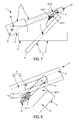
- Such a closure device 1 comprises a roof window 2 which comprises a frame 3 intended to be fixed on the roof frame, and constituted by a frame having lateral sides 30 (extending substantially along the slope of the roof) and only transverse sides (extending substantially horizontally and perpendicular to the lateral sides).
- This roof window 2 also comprises an opening 4, movable relative to said frame 3, and comprising, on the one hand, a glazed part and, on the other hand, a frame consisting of lateral uprights 40 and cross members, and receiving said glazed portion.
- this roof window 2 comprises at least one means 5 for mounting such an opening 4 pivotally relative to the frame 3, more particularly along a horizontal axis.
- Such a closure device 1 also comprises a roller shutter 6 which comprises an apron (not shown) and a housing 7 inside which wraps and outside which unfolds said apron.
- This shutter 6 comprises, again, lateral uprights 8, surmounted by said housing 7, and each incorporating a guide slide 80, on the one hand, which is oriented towards the other lateral upright 8 and inwardly of the shutter 6 and, on the other hand, inside which guide slide 80 is guided a lateral end of said apron.
- Such roller shutter 6 equips the roof window 2 mentioned above, more particularly by surmounting this roof window 2.
- the lateral uprights 8 of this shutter 6 surmount the lateral uprights 40 of the frame of the opening 4 of this roof window 2.
- Such a shutter 6 is, again, movable relative to such a roof window 2.
- the closure device 1 then comprises at least one means 9 for mounting the roller shutter 6 pivotally relative to the frame 3 of the roof window 2, more particularly with respect to the upper end. 31 of this chassis 3. This or these means 9 then allow this roller shutter 6 to be movable relative to the chassis 3.
- such a means 9 for mounting the shutter 6 pivotally relative to the frame 3 of the roof window 2 comprises a bracket 90, extending from the upper end 31 of the frame 3 of the roof window 2, more particularly in the extension of a lateral side 30 of this frame 3.
- a console 90 has a free end 91, offset with respect to this frame 3 (more particularly with respect to the upper end 31 of this frame 3 ), and on which is pivotally mounted the roller shutter 6, more particularly the upper end of the roller shutter 6 and / or the housing 7 that comprises the roller shutter 6 (including that comprises the upper end of the roller shutter 6 ).
- a preferred embodiment is that such a bracket 90 adopts the shape of a bracket or the like.
- the closure device 1 also comprises at least one system 10 for mounting the roller shutter 6 in pivoting and in translation with respect to the opening 4 of the roof window 2, such a system 10 also allowing this roller shutter 6 to be movable relative to this opening 4.
- Such a system 10 for mounting the shutter 6 pivotally and in translation relative to the opening 4 comprises, firstly, a member 11 associated with said opening 4 and, secondly, a means 12 for mounting the shutter rolling 6 in rotation and in translation relative to this member 11.
- the means 12 for mounting the roller shutter 6 pivotally and in translation relative to this member 11 comprises, on the one hand, a mounting slide 120 that includes the shutter 6, on the other hand , a movable member 121 slidably mounted within this mounting slide 120 and, secondly, a piece 122 for mounting said member 11 pivotally on the movable member 121.
- such a means 12 comprises a mounting slide 120 that comprises the roller shutter 6.
- this roller shutter 6 comprises lateral uprights 8 each incorporating a guide slide 80 inside. of which is guided the rolling shutter apron 6.
- Such a lateral amount 8 incorporates, then also, such a mounting slide 120, facing outwardly of the shutter 6, having an opening oriented in a direction opposite to the opening of the guide slide 80, and having a bottom also constituting the bottom of such a guide slide 80.
- such a lateral amount 8 is constituted by a profile, in particular metal and / or extruded.
- the movable member 121 it takes the form of a roller, a pad, a slider or the like while the workpiece 122 adopts the shape of a shaft or the like.
- the closure device 1 comprises at least system 10 for mounting the shutter 6 pivotally and in translation relative to the opening 4 of the roof window 2, such a system 10 comprising a member 11 associated with said opening 4.
- the system or systems 10 for mounting the shutter 6 pivotally and in translation relative to the opening 4 of the roof window 2 comprise, again, a means 13 for mounting the member 11 of a such system 10 moving relative to this opening 4.
- Such a means 13 then makes it possible to mount such a member 11 movably with respect to said opening of the roof window 2.
- this means 13 for mounting the member 11 in displacement relative to the opening 4 is constituted by a means 13 for mounting the member 11 in sliding relative to this opening 4.
- such an opening 4 comprises lateral uprights 40.
- the means 13 for mounting the member 11 in sliding relative to this opening 4 is then designed to mount this member 11 sliding longitudinally relative to such a lateral amount 40.
- the means 13 for mounting the member 11 in sliding relative to the opening 4 comprises, on the one hand, a slide 130 which equips this opening 4 (more particularly a lateral amount 40 that includes such an opening 4) and, secondly, a movable member 131, slidably mounted within such a slide 130, and at least partially constituting or receiving such a member 11.
- closure device 1 comprises at least one means 14 for positioning the shutter 6 recessed relative to the opening 4 of the roof window 2.
- Such a means for positioning 14 comprises a support 15 equipping this opening 4, more particularly a lateral upright 40 of such an opening 4, in particular the lower end of such a lateral upright 40.
- such a support 15 equips this opening 4 being attached to such an opening 4, more particularly to a lateral amount 40 of such an opening 4, in particular on the lower end of such a lateral amount 40, this by via a base 150 that includes such a support 15 and which is fixed on the opening 4.
- Such a support 15 extends from this opening 4, more particularly from the lateral upright 40 of such an opening 4, in particular from the lower end of such a lateral upright 40, this in a manner perpendicular to the plane of opening 4 and towards shutter 6.
- Such a support 15 has a free end 151 comprising the means 13 for mounting the member 11 in displacement with respect to this opening 4, more particularly the slide 130 that comprises this means 13.
- this support 15 is constituted by a profile, in particular metal.
- the means 14 for positioning the rolling shutter 6 with respect to the opening 4 of the roof window 2 comprises, again and according to a first embodiment, a sliding shoe 16 extending laterally with respect to said opening and in direction of roller shutter 6.
- Such sliding shoe 16 is designed to bear against this shutter 6, particularly during the opening and closing maneuvers of the closure device 1.
- the opening 4 of the roof window 2 (in particular the lower end of the lateral pillar 40 of such an opening 4) which comprises such a sliding pad 16.
- a particular embodiment is that such a sliding pad 16 is part of the support 15 mentioned above and that comprises the means 14 for positioning the shutter 6 recessed relative to the opening 4 of the roof window 2.
- this sliding pad 16 is designed, when opening the closure device 1, to bear against the shutter 6 (more particularly against a lateral amount 8 of this shutter 6) which has the effect, on the one hand, to position (more particularly maintain) the shutter 6 recessed from the opening 4 and, secondly, to cause the displacement of the movable member 131 (and, therefore, the member 11) relative to the slide 130, more particularly towards the lower end of the lateral upright 40 of the opening 4 and / or towards the outside of this slide 130.
- the sliding pad 16 no longer bears against the shutter 6 and the movable member 121 bears against a stop 123 that includes the mounting slide 120 which causes the movable element 131 to move relative to the slide 130 in a direction opposite to that of the lower end of the lateral upright 40 of the opening 4 and / or towards the inside of this slide 130.
- the means 14 for positioning the shutter 6 recessed with respect to the opening 4 of the roof window 2 comprises, again and according to a second embodiment, a return spring. 17 designed to push the member 11 towards the shutter 6.
- such a spring 17 is interposed between the member 11 (more particularly the movable member 131 which is at least partly such a member 11 or which receives such a member 11) and a fixed point relative to the opening 4.
- such a spring 17 is positioned inside the slide 130 of the means 13 to mount the member 11 in sliding relative to the opening 4.
- the movable element 131 (and, therefore, the member 11) adopts a retracted position inside the slide 130.
- the spring 17 acts on the movable element 131 (and, therefore, on the member 11) to, firstly, hold the movable member 121 in position. bearing against the stop 123 of the mounting slide 120 and, secondly, cause the displacement of this movable member 131 (and, therefore, of this member 11) relative to the slide 130, more particularly in the direction of the lower end of the lateral upright 40 of the opening 4 and / or towards the outside of this slide 130.
- the action of this spring 17 on this mobile element 131 makes it possible to position (more particularly to maintain) the shutter 6 recessed with respect to the opening 4.
- closure device 1 comprises at least one means for tapping the spring 17, more particularly according to the weight of the shutter 6.
- such a means for tapping 18 is constituted by a slider whose position is adjustable relative to the opening 4 while the spring 17 is interposed between this slider and said member 11, more particularly between this slider and the element.
- mobile 131 which is at least in part such a member 11 or which receives such a member 11.
- Such a means for tapping 18 is, in fact, a fixed point as mentioned above and adjustable type.
Landscapes
- Engineering & Computer Science (AREA)
- Structural Engineering (AREA)
- Architecture (AREA)
- Civil Engineering (AREA)
- Operating, Guiding And Securing Of Roll- Type Closing Members (AREA)
Applications Claiming Priority (1)
| Application Number | Priority Date | Filing Date | Title |
|---|---|---|---|
| FR1361181A FR3013370B1 (fr) | 2013-11-15 | 2013-11-15 | Dispositif de fermeture d'une ouverture d'un toit |
Publications (2)
| Publication Number | Publication Date |
|---|---|
| EP2873783A1 true EP2873783A1 (de) | 2015-05-20 |
| EP2873783B1 EP2873783B1 (de) | 2016-07-06 |
Family
ID=49998490
Family Applications (1)
| Application Number | Title | Priority Date | Filing Date |
|---|---|---|---|
| EP14192477.9A Active EP2873783B1 (de) | 2013-11-15 | 2014-11-10 | Vorrichtung zum Verschließen einer Dachöffnung |
Country Status (4)
| Country | Link |
|---|---|
| EP (1) | EP2873783B1 (de) |
| ES (1) | ES2590985T3 (de) |
| FR (1) | FR3013370B1 (de) |
| PL (1) | PL2873783T3 (de) |
Cited By (2)
| Publication number | Priority date | Publication date | Assignee | Title |
|---|---|---|---|---|
| EP3299532A1 (de) | 2016-09-22 | 2018-03-28 | Roto Frank AG | Dachfenster |
| CN112277600A (zh) * | 2020-11-16 | 2021-01-29 | 湘潭毓恬冠佳汽车零部件有限公司 | 一种汽车天窗用挡风网起降结构 |
Families Citing this family (1)
| Publication number | Priority date | Publication date | Assignee | Title |
|---|---|---|---|---|
| CN112049335B (zh) * | 2020-08-25 | 2021-12-07 | 安徽银羽门窗科技有限公司 | 一种建筑物顶楼天窗 |
Citations (3)
| Publication number | Priority date | Publication date | Assignee | Title |
|---|---|---|---|---|
| DE9202869U1 (de) * | 1992-03-05 | 1992-05-07 | Warema Renkhoff Gmbh, 97828 Marktheidenfeld | Fenster mit Rolladen für schräge Dachflächen |
| FR2717854A1 (fr) * | 1994-03-23 | 1995-09-29 | Unaferm Sa | Perfectionnement des volets roulants pour fenêtres de toiture. |
| BE1015350A3 (nl) * | 2003-02-06 | 2005-02-01 | Lijnen Invest Nv | Dakraam. |
-
2013
- 2013-11-15 FR FR1361181A patent/FR3013370B1/fr not_active Expired - Fee Related
-
2014
- 2014-11-10 ES ES14192477.9T patent/ES2590985T3/es active Active
- 2014-11-10 EP EP14192477.9A patent/EP2873783B1/de active Active
- 2014-11-10 PL PL14192477T patent/PL2873783T3/pl unknown
Patent Citations (3)
| Publication number | Priority date | Publication date | Assignee | Title |
|---|---|---|---|---|
| DE9202869U1 (de) * | 1992-03-05 | 1992-05-07 | Warema Renkhoff Gmbh, 97828 Marktheidenfeld | Fenster mit Rolladen für schräge Dachflächen |
| FR2717854A1 (fr) * | 1994-03-23 | 1995-09-29 | Unaferm Sa | Perfectionnement des volets roulants pour fenêtres de toiture. |
| BE1015350A3 (nl) * | 2003-02-06 | 2005-02-01 | Lijnen Invest Nv | Dakraam. |
Cited By (2)
| Publication number | Priority date | Publication date | Assignee | Title |
|---|---|---|---|---|
| EP3299532A1 (de) | 2016-09-22 | 2018-03-28 | Roto Frank AG | Dachfenster |
| CN112277600A (zh) * | 2020-11-16 | 2021-01-29 | 湘潭毓恬冠佳汽车零部件有限公司 | 一种汽车天窗用挡风网起降结构 |
Also Published As
| Publication number | Publication date |
|---|---|
| FR3013370A1 (fr) | 2015-05-22 |
| FR3013370B1 (fr) | 2016-01-01 |
| PL2873783T3 (pl) | 2017-01-31 |
| EP2873783B1 (de) | 2016-07-06 |
| ES2590985T3 (es) | 2016-11-24 |
Similar Documents
| Publication | Publication Date | Title |
|---|---|---|
| EP2873783B1 (de) | Vorrichtung zum Verschließen einer Dachöffnung | |
| EP0544582B1 (de) | Führungsvorrichtung einer Schiebeöffnung, zum Beispiel einer Schiebetür, insbesondere für ein Kraftfahrzeug | |
| FR2911619A1 (fr) | Dispositif a caisson mobile. | |
| WO2007096540A1 (fr) | Dispositif de montage articule d'une vitre sur une porte sans cadre de vehicule de type cabriolet ou coupe | |
| EP3401484A1 (de) | Gebäudeöffnungselemente wie türen oder fenster mit hebe- und schiebeflügel und stossdämpfungselement | |
| FR3021253A1 (fr) | Dispositif vitre affleurant pour porte de vehicule a panneau mobile reglable, porte et vehicule automobile correspondants. | |
| FR2779996A1 (fr) | Dispositif de guidage pour porte coulissante de vehicules automobiles | |
| EP2942472B1 (de) | Verschlussvorrichtung vom typ jalousie, rollladen oder ähnliches, insbesondere für ein dachfenster | |
| FR3033357A1 (fr) | Ouvrant, tel qu'une porte de placard, comprenant des dispositifs de pivotement inferieur et superieur, et ensemble correspondant | |
| EP0377545B1 (de) | Schiebeflügel | |
| FR3010662A1 (fr) | Deflecteur de vent pour toit d'un vehicule automobile | |
| FR3007447A1 (fr) | Dispositif de correction de la fleche verticale d'une traverse superieure de la menuiserie d'un systeme de fermeture | |
| EP3293334A1 (de) | Betätigungsvorrichtung eines fensters oder einer tür, und fenster oder tür mit einer solchen vorrichtung | |
| EP3081725B1 (de) | Zwischenbeschlag für schliesssystem | |
| EP0877141B1 (de) | Automatisch einziehbare Dichtung für eine Türschwelle | |
| FR3096714A3 (fr) | Charnière de type à peigne pour fenêtre et portes à vantail pivotant | |
| FR2755719A1 (fr) | Dispositif de fermeture d'un ouvrant a frappe, pour porte, fenetre ou analogue | |
| FR3085989A1 (fr) | Dispositif de fermeture ou d'occultation pour une construction | |
| EP2549052B1 (de) | Vorrichtung zum Anlegen von Spannung an ein Steuermittel für die Ausrichtung mindestens einer beweglichen Lamelle eines Behangs für eine Verdunkelungsvorrichtung | |
| FR1239994A (fr) | Perfectionnements à la commande des châssis basculants | |
| FR2500046A3 (fr) | Dispositif de guidage pour l'ouvrant, de preference relevable et coulissant, d'une fenetre ou d'une porte | |
| FR3112804A1 (fr) | Ouvrant perfectionné pour un bâtiment ou un meuble | |
| FR2820166A1 (fr) | Dispositif de commande de mouvement pour ouvrant, notamment pour portail | |
| FR2949502A1 (fr) | Dispositif de reglage de la position d'un rail de guidage d'une porte laterale coulissante d'un vehicule automobile et vehicule equipe d'un tel dispositif. | |
| BE396690A (de) |
Legal Events
| Date | Code | Title | Description |
|---|---|---|---|
| PUAI | Public reference made under article 153(3) epc to a published international application that has entered the european phase |
Free format text: ORIGINAL CODE: 0009012 |
|
| 17P | Request for examination filed |
Effective date: 20141110 |
|
| AK | Designated contracting states |
Kind code of ref document: A1 Designated state(s): AL AT BE BG CH CY CZ DE DK EE ES FI FR GB GR HR HU IE IS IT LI LT LU LV MC MK MT NL NO PL PT RO RS SE SI SK SM TR |
|
| AX | Request for extension of the european patent |
Extension state: BA ME |
|
| R17P | Request for examination filed (corrected) |
Effective date: 20151103 |
|
| RBV | Designated contracting states (corrected) |
Designated state(s): AL AT BE BG CH CY CZ DE DK EE ES FI FR GB GR HR HU IE IS IT LI LT LU LV MC MK MT NL NO PL PT RO RS SE SI SK SM TR |
|
| GRAP | Despatch of communication of intention to grant a patent |
Free format text: ORIGINAL CODE: EPIDOSNIGR1 |
|
| INTG | Intention to grant announced |
Effective date: 20160310 |
|
| GRAS | Grant fee paid |
Free format text: ORIGINAL CODE: EPIDOSNIGR3 |
|
| GRAA | (expected) grant |
Free format text: ORIGINAL CODE: 0009210 |
|
| AK | Designated contracting states |
Kind code of ref document: B1 Designated state(s): AL AT BE BG CH CY CZ DE DK EE ES FI FR GB GR HR HU IE IS IT LI LT LU LV MC MK MT NL NO PL PT RO RS SE SI SK SM TR |
|
| REG | Reference to a national code |
Ref country code: GB Ref legal event code: FG4D Free format text: NOT ENGLISH |
|
| REG | Reference to a national code |
Ref country code: AT Ref legal event code: REF Ref document number: 810833 Country of ref document: AT Kind code of ref document: T Effective date: 20160715 Ref country code: CH Ref legal event code: EP |
|
| REG | Reference to a national code |
Ref country code: IE Ref legal event code: FG4D Free format text: LANGUAGE OF EP DOCUMENT: FRENCH |
|
| REG | Reference to a national code |
Ref country code: DE Ref legal event code: R096 Ref document number: 602014002577 Country of ref document: DE |
|
| REG | Reference to a national code |
Ref country code: NL Ref legal event code: MP Effective date: 20160706 |
|
| REG | Reference to a national code |
Ref country code: LT Ref legal event code: MG4D |
|
| REG | Reference to a national code |
Ref country code: ES Ref legal event code: FG2A Ref document number: 2590985 Country of ref document: ES Kind code of ref document: T3 Effective date: 20161124 |
|
| REG | Reference to a national code |
Ref country code: FR Ref legal event code: PLFP Year of fee payment: 3 |
|
| REG | Reference to a national code |
Ref country code: AT Ref legal event code: MK05 Ref document number: 810833 Country of ref document: AT Kind code of ref document: T Effective date: 20160706 |
|
| PG25 | Lapsed in a contracting state [announced via postgrant information from national office to epo] |
Ref country code: FI Free format text: LAPSE BECAUSE OF FAILURE TO SUBMIT A TRANSLATION OF THE DESCRIPTION OR TO PAY THE FEE WITHIN THE PRESCRIBED TIME-LIMIT Effective date: 20160706 Ref country code: HR Free format text: LAPSE BECAUSE OF FAILURE TO SUBMIT A TRANSLATION OF THE DESCRIPTION OR TO PAY THE FEE WITHIN THE PRESCRIBED TIME-LIMIT Effective date: 20160706 Ref country code: NO Free format text: LAPSE BECAUSE OF FAILURE TO SUBMIT A TRANSLATION OF THE DESCRIPTION OR TO PAY THE FEE WITHIN THE PRESCRIBED TIME-LIMIT Effective date: 20161006 Ref country code: NL Free format text: LAPSE BECAUSE OF FAILURE TO SUBMIT A TRANSLATION OF THE DESCRIPTION OR TO PAY THE FEE WITHIN THE PRESCRIBED TIME-LIMIT Effective date: 20160706 Ref country code: IS Free format text: LAPSE BECAUSE OF FAILURE TO SUBMIT A TRANSLATION OF THE DESCRIPTION OR TO PAY THE FEE WITHIN THE PRESCRIBED TIME-LIMIT Effective date: 20161106 Ref country code: RS Free format text: LAPSE BECAUSE OF FAILURE TO SUBMIT A TRANSLATION OF THE DESCRIPTION OR TO PAY THE FEE WITHIN THE PRESCRIBED TIME-LIMIT Effective date: 20160706 Ref country code: LT Free format text: LAPSE BECAUSE OF FAILURE TO SUBMIT A TRANSLATION OF THE DESCRIPTION OR TO PAY THE FEE WITHIN THE PRESCRIBED TIME-LIMIT Effective date: 20160706 |
|
| PG25 | Lapsed in a contracting state [announced via postgrant information from national office to epo] |
Ref country code: SE Free format text: LAPSE BECAUSE OF FAILURE TO SUBMIT A TRANSLATION OF THE DESCRIPTION OR TO PAY THE FEE WITHIN THE PRESCRIBED TIME-LIMIT Effective date: 20160706 Ref country code: GR Free format text: LAPSE BECAUSE OF FAILURE TO SUBMIT A TRANSLATION OF THE DESCRIPTION OR TO PAY THE FEE WITHIN THE PRESCRIBED TIME-LIMIT Effective date: 20161007 Ref country code: AT Free format text: LAPSE BECAUSE OF FAILURE TO SUBMIT A TRANSLATION OF THE DESCRIPTION OR TO PAY THE FEE WITHIN THE PRESCRIBED TIME-LIMIT Effective date: 20160706 Ref country code: PT Free format text: LAPSE BECAUSE OF FAILURE TO SUBMIT A TRANSLATION OF THE DESCRIPTION OR TO PAY THE FEE WITHIN THE PRESCRIBED TIME-LIMIT Effective date: 20161107 Ref country code: LV Free format text: LAPSE BECAUSE OF FAILURE TO SUBMIT A TRANSLATION OF THE DESCRIPTION OR TO PAY THE FEE WITHIN THE PRESCRIBED TIME-LIMIT Effective date: 20160706 Ref country code: BE Free format text: LAPSE BECAUSE OF NON-PAYMENT OF DUE FEES Effective date: 20161130 |
|
| REG | Reference to a national code |
Ref country code: DE Ref legal event code: R097 Ref document number: 602014002577 Country of ref document: DE |
|
| PG25 | Lapsed in a contracting state [announced via postgrant information from national office to epo] |
Ref country code: EE Free format text: LAPSE BECAUSE OF FAILURE TO SUBMIT A TRANSLATION OF THE DESCRIPTION OR TO PAY THE FEE WITHIN THE PRESCRIBED TIME-LIMIT Effective date: 20160706 Ref country code: RO Free format text: LAPSE BECAUSE OF FAILURE TO SUBMIT A TRANSLATION OF THE DESCRIPTION OR TO PAY THE FEE WITHIN THE PRESCRIBED TIME-LIMIT Effective date: 20160706 |
|
| PLBE | No opposition filed within time limit |
Free format text: ORIGINAL CODE: 0009261 |
|
| STAA | Information on the status of an ep patent application or granted ep patent |
Free format text: STATUS: NO OPPOSITION FILED WITHIN TIME LIMIT |
|
| PG25 | Lapsed in a contracting state [announced via postgrant information from national office to epo] |
Ref country code: SM Free format text: LAPSE BECAUSE OF FAILURE TO SUBMIT A TRANSLATION OF THE DESCRIPTION OR TO PAY THE FEE WITHIN THE PRESCRIBED TIME-LIMIT Effective date: 20160706 Ref country code: DK Free format text: LAPSE BECAUSE OF FAILURE TO SUBMIT A TRANSLATION OF THE DESCRIPTION OR TO PAY THE FEE WITHIN THE PRESCRIBED TIME-LIMIT Effective date: 20160706 Ref country code: CZ Free format text: LAPSE BECAUSE OF FAILURE TO SUBMIT A TRANSLATION OF THE DESCRIPTION OR TO PAY THE FEE WITHIN THE PRESCRIBED TIME-LIMIT Effective date: 20160706 Ref country code: SK Free format text: LAPSE BECAUSE OF FAILURE TO SUBMIT A TRANSLATION OF THE DESCRIPTION OR TO PAY THE FEE WITHIN THE PRESCRIBED TIME-LIMIT Effective date: 20160706 Ref country code: BG Free format text: LAPSE BECAUSE OF FAILURE TO SUBMIT A TRANSLATION OF THE DESCRIPTION OR TO PAY THE FEE WITHIN THE PRESCRIBED TIME-LIMIT Effective date: 20161006 |
|
| 26N | No opposition filed |
Effective date: 20170407 |
|
| REG | Reference to a national code |
Ref country code: IE Ref legal event code: MM4A |
|
| PG25 | Lapsed in a contracting state [announced via postgrant information from national office to epo] |
Ref country code: SI Free format text: LAPSE BECAUSE OF FAILURE TO SUBMIT A TRANSLATION OF THE DESCRIPTION OR TO PAY THE FEE WITHIN THE PRESCRIBED TIME-LIMIT Effective date: 20160706 |
|
| PG25 | Lapsed in a contracting state [announced via postgrant information from national office to epo] |
Ref country code: LU Free format text: LAPSE BECAUSE OF NON-PAYMENT OF DUE FEES Effective date: 20161130 |
|
| REG | Reference to a national code |
Ref country code: FR Ref legal event code: PLFP Year of fee payment: 4 |
|
| PG25 | Lapsed in a contracting state [announced via postgrant information from national office to epo] |
Ref country code: IE Free format text: LAPSE BECAUSE OF NON-PAYMENT OF DUE FEES Effective date: 20161110 |
|
| REG | Reference to a national code |
Ref country code: BE Ref legal event code: MM Effective date: 20161130 |
|
| PG25 | Lapsed in a contracting state [announced via postgrant information from national office to epo] |
Ref country code: HU Free format text: LAPSE BECAUSE OF FAILURE TO SUBMIT A TRANSLATION OF THE DESCRIPTION OR TO PAY THE FEE WITHIN THE PRESCRIBED TIME-LIMIT; INVALID AB INITIO Effective date: 20141110 |
|
| PG25 | Lapsed in a contracting state [announced via postgrant information from national office to epo] |
Ref country code: MK Free format text: LAPSE BECAUSE OF FAILURE TO SUBMIT A TRANSLATION OF THE DESCRIPTION OR TO PAY THE FEE WITHIN THE PRESCRIBED TIME-LIMIT Effective date: 20160706 Ref country code: CY Free format text: LAPSE BECAUSE OF FAILURE TO SUBMIT A TRANSLATION OF THE DESCRIPTION OR TO PAY THE FEE WITHIN THE PRESCRIBED TIME-LIMIT Effective date: 20160706 Ref country code: MC Free format text: LAPSE BECAUSE OF FAILURE TO SUBMIT A TRANSLATION OF THE DESCRIPTION OR TO PAY THE FEE WITHIN THE PRESCRIBED TIME-LIMIT Effective date: 20160706 |
|
| PG25 | Lapsed in a contracting state [announced via postgrant information from national office to epo] |
Ref country code: LI Free format text: LAPSE BECAUSE OF NON-PAYMENT OF DUE FEES Effective date: 20171130 Ref country code: CH Free format text: LAPSE BECAUSE OF NON-PAYMENT OF DUE FEES Effective date: 20171130 |
|
| PG25 | Lapsed in a contracting state [announced via postgrant information from national office to epo] |
Ref country code: MT Free format text: LAPSE BECAUSE OF FAILURE TO SUBMIT A TRANSLATION OF THE DESCRIPTION OR TO PAY THE FEE WITHIN THE PRESCRIBED TIME-LIMIT Effective date: 20160706 |
|
| PG25 | Lapsed in a contracting state [announced via postgrant information from national office to epo] |
Ref country code: AL Free format text: LAPSE BECAUSE OF FAILURE TO SUBMIT A TRANSLATION OF THE DESCRIPTION OR TO PAY THE FEE WITHIN THE PRESCRIBED TIME-LIMIT Effective date: 20160706 Ref country code: TR Free format text: LAPSE BECAUSE OF FAILURE TO SUBMIT A TRANSLATION OF THE DESCRIPTION OR TO PAY THE FEE WITHIN THE PRESCRIBED TIME-LIMIT Effective date: 20160706 |
|
| GBPC | Gb: european patent ceased through non-payment of renewal fee |
Effective date: 20181110 |
|
| PG25 | Lapsed in a contracting state [announced via postgrant information from national office to epo] |
Ref country code: GB Free format text: LAPSE BECAUSE OF NON-PAYMENT OF DUE FEES Effective date: 20181110 |
|
| PGFP | Annual fee paid to national office [announced via postgrant information from national office to epo] |
Ref country code: DE Payment date: 20251117 Year of fee payment: 12 |
|
| PGFP | Annual fee paid to national office [announced via postgrant information from national office to epo] |
Ref country code: IT Payment date: 20251111 Year of fee payment: 12 |
|
| PGFP | Annual fee paid to national office [announced via postgrant information from national office to epo] |
Ref country code: FR Payment date: 20251021 Year of fee payment: 12 |
|
| PGFP | Annual fee paid to national office [announced via postgrant information from national office to epo] |
Ref country code: PL Payment date: 20251020 Year of fee payment: 12 |
|
| PGFP | Annual fee paid to national office [announced via postgrant information from national office to epo] |
Ref country code: ES Payment date: 20251210 Year of fee payment: 12 |