EP2876379A1 - Frontpaneel einer Innenraumeinheit und Herstellungsverfahren dafür - Google Patents
Frontpaneel einer Innenraumeinheit und Herstellungsverfahren dafür Download PDFInfo
- Publication number
- EP2876379A1 EP2876379A1 EP14193111.3A EP14193111A EP2876379A1 EP 2876379 A1 EP2876379 A1 EP 2876379A1 EP 14193111 A EP14193111 A EP 14193111A EP 2876379 A1 EP2876379 A1 EP 2876379A1
- Authority
- EP
- European Patent Office
- Prior art keywords
- injection
- front panel
- molded part
- section
- indoor unit
- Prior art date
- Legal status (The legal status is an assumption and is not a legal conclusion. Google has not performed a legal analysis and makes no representation as to the accuracy of the status listed.)
- Granted
Links
Images



Classifications
-
- F—MECHANICAL ENGINEERING; LIGHTING; HEATING; WEAPONS; BLASTING
- F25—REFRIGERATION OR COOLING; COMBINED HEATING AND REFRIGERATION SYSTEMS; HEAT PUMP SYSTEMS; MANUFACTURE OR STORAGE OF ICE; LIQUEFACTION SOLIDIFICATION OF GASES
- F25D—REFRIGERATORS; COLD ROOMS; ICE-BOXES; COOLING OR FREEZING APPARATUS NOT OTHERWISE PROVIDED FOR
- F25D23/00—General constructional features
-
- F—MECHANICAL ENGINEERING; LIGHTING; HEATING; WEAPONS; BLASTING
- F24—HEATING; RANGES; VENTILATING
- F24F—AIR-CONDITIONING; AIR-HUMIDIFICATION; VENTILATION; USE OF AIR CURRENTS FOR SCREENING
- F24F1/00—Room units for air-conditioning, e.g. separate or self-contained units or units receiving primary air from a central station
-
- B—PERFORMING OPERATIONS; TRANSPORTING
- B29—WORKING OF PLASTICS; WORKING OF SUBSTANCES IN A PLASTIC STATE IN GENERAL
- B29C—SHAPING OR JOINING OF PLASTICS; SHAPING OF MATERIAL IN A PLASTIC STATE, NOT OTHERWISE PROVIDED FOR; AFTER-TREATMENT OF THE SHAPED PRODUCTS, e.g. REPAIRING
- B29C45/00—Injection moulding, i.e. forcing the required volume of moulding material through a nozzle into a closed mould; Apparatus therefor
- B29C45/16—Making multilayered or multicoloured articles
-
- B—PERFORMING OPERATIONS; TRANSPORTING
- B29—WORKING OF PLASTICS; WORKING OF SUBSTANCES IN A PLASTIC STATE IN GENERAL
- B29C—SHAPING OR JOINING OF PLASTICS; SHAPING OF MATERIAL IN A PLASTIC STATE, NOT OTHERWISE PROVIDED FOR; AFTER-TREATMENT OF THE SHAPED PRODUCTS, e.g. REPAIRING
- B29C45/00—Injection moulding, i.e. forcing the required volume of moulding material through a nozzle into a closed mould; Apparatus therefor
- B29C45/16—Making multilayered or multicoloured articles
- B29C45/1615—The materials being injected at different moulding stations
- B29C45/162—The materials being injected at different moulding stations using means, e.g. mould parts, for transferring an injected part between moulding stations
-
- F—MECHANICAL ENGINEERING; LIGHTING; HEATING; WEAPONS; BLASTING
- F24—HEATING; RANGES; VENTILATING
- F24F—AIR-CONDITIONING; AIR-HUMIDIFICATION; VENTILATION; USE OF AIR CURRENTS FOR SCREENING
- F24F13/00—Details common to, or for air-conditioning, air-humidification, ventilation or use of air currents for screening
- F24F13/08—Air-flow control members, e.g. louvres, grilles, flaps or guide plates
- F24F13/082—Grilles, registers or guards
-
- F—MECHANICAL ENGINEERING; LIGHTING; HEATING; WEAPONS; BLASTING
- F24—HEATING; RANGES; VENTILATING
- F24F—AIR-CONDITIONING; AIR-HUMIDIFICATION; VENTILATION; USE OF AIR CURRENTS FOR SCREENING
- F24F13/00—Details common to, or for air-conditioning, air-humidification, ventilation or use of air currents for screening
- F24F13/20—Casings or covers
-
- B—PERFORMING OPERATIONS; TRANSPORTING
- B29—WORKING OF PLASTICS; WORKING OF SUBSTANCES IN A PLASTIC STATE IN GENERAL
- B29C—SHAPING OR JOINING OF PLASTICS; SHAPING OF MATERIAL IN A PLASTIC STATE, NOT OTHERWISE PROVIDED FOR; AFTER-TREATMENT OF THE SHAPED PRODUCTS, e.g. REPAIRING
- B29C45/00—Injection moulding, i.e. forcing the required volume of moulding material through a nozzle into a closed mould; Apparatus therefor
- B29C45/16—Making multilayered or multicoloured articles
- B29C2045/1682—Making multilayered or multicoloured articles preventing defects
-
- B—PERFORMING OPERATIONS; TRANSPORTING
- B29—WORKING OF PLASTICS; WORKING OF SUBSTANCES IN A PLASTIC STATE IN GENERAL
- B29C—SHAPING OR JOINING OF PLASTICS; SHAPING OF MATERIAL IN A PLASTIC STATE, NOT OTHERWISE PROVIDED FOR; AFTER-TREATMENT OF THE SHAPED PRODUCTS, e.g. REPAIRING
- B29C45/00—Injection moulding, i.e. forcing the required volume of moulding material through a nozzle into a closed mould; Apparatus therefor
- B29C45/16—Making multilayered or multicoloured articles
- B29C2045/1687—Making multilayered or multicoloured articles preventing leakage of second injected material from the mould cavity
-
- B—PERFORMING OPERATIONS; TRANSPORTING
- B29—WORKING OF PLASTICS; WORKING OF SUBSTANCES IN A PLASTIC STATE IN GENERAL
- B29C—SHAPING OR JOINING OF PLASTICS; SHAPING OF MATERIAL IN A PLASTIC STATE, NOT OTHERWISE PROVIDED FOR; AFTER-TREATMENT OF THE SHAPED PRODUCTS, e.g. REPAIRING
- B29C45/00—Injection moulding, i.e. forcing the required volume of moulding material through a nozzle into a closed mould; Apparatus therefor
- B29C45/16—Making multilayered or multicoloured articles
- B29C2045/1698—Making multilayered or multicoloured articles multicoloured articles moulded in one step
-
- B—PERFORMING OPERATIONS; TRANSPORTING
- B29—WORKING OF PLASTICS; WORKING OF SUBSTANCES IN A PLASTIC STATE IN GENERAL
- B29K—INDEXING SCHEME ASSOCIATED WITH SUBCLASSES B29B, B29C OR B29D, RELATING TO MOULDING MATERIALS OR TO MATERIALS FOR MOULDS, REINFORCEMENTS, FILLERS OR PREFORMED PARTS, e.g. INSERTS
- B29K2995/00—Properties of moulding materials, reinforcements, fillers, preformed parts or moulds
- B29K2995/0018—Properties of moulding materials, reinforcements, fillers, preformed parts or moulds having particular optical properties, e.g. fluorescent or phosphorescent
- B29K2995/002—Coloured
-
- B—PERFORMING OPERATIONS; TRANSPORTING
- B29—WORKING OF PLASTICS; WORKING OF SUBSTANCES IN A PLASTIC STATE IN GENERAL
- B29K—INDEXING SCHEME ASSOCIATED WITH SUBCLASSES B29B, B29C OR B29D, RELATING TO MOULDING MATERIALS OR TO MATERIALS FOR MOULDS, REINFORCEMENTS, FILLERS OR PREFORMED PARTS, e.g. INSERTS
- B29K2995/00—Properties of moulding materials, reinforcements, fillers, preformed parts or moulds
- B29K2995/0018—Properties of moulding materials, reinforcements, fillers, preformed parts or moulds having particular optical properties, e.g. fluorescent or phosphorescent
- B29K2995/0026—Transparent
-
- B—PERFORMING OPERATIONS; TRANSPORTING
- B29—WORKING OF PLASTICS; WORKING OF SUBSTANCES IN A PLASTIC STATE IN GENERAL
- B29L—INDEXING SCHEME ASSOCIATED WITH SUBCLASS B29C, RELATING TO PARTICULAR ARTICLES
- B29L2031/00—Other particular articles
- B29L2031/18—Heat-exchangers or parts thereof
Definitions
- Embodiments disclosed herein relate to a front panel of an indoor unit of an air-conditioner and a manufacturing method thereof.
- an air-conditioner refers to a device which keeps indoor air pleasant and suitable for human activity by using a cooling cycle.
- the air-conditioner serves to air-condition a room by repeatedly sucking in warm indoor air, heat-exchanging the sucked-in air with a low temperature refrigerant and then discharging the heat-exchanged cold air into the room, or to heat the room through a reverse operation.
- the air-conditioner may air-condition or heat the room using the cooling cycle in which the refrigerant is circulated in a forward or in a reverse direction through a compressor, a condenser, an expansion valve and an evaporator.
- the compressor provides a gaseous refrigerant which is a high temperature and has a high pressure
- the condenser provides a liquid refrigerant which is room temperature and has a high pressure.
- the expansion valve depressurizes the liquid refrigerant which is room temperature and has a high pressure
- the evaporator evaporates the depressurized refrigerant into the gaseous refrigerant having a low temperature.
- a ceiling type air-conditioner may include an indoor unit and an outdoor unit which are separated from each other.
- the indoor unit may be a device which is installed at a ceiling of an indoor space so as to air-condition or heat the room.
- the ceiling type air-conditioner may include a main body which is disposed in an inner side of the ceiling of the indoor space, and a front panel which is attached to a front surface of the main body so as to be exposed from the ceiling.
- An air inlet port for sucking air into the main body may be formed at one side of the front panel, and an outlet port for discharging the air air-conditioned through a heat exchanger installed in the main body to the room may be formed at the other side thereof.
- a front panel of an indoor unit may include a suction grill in which a plurality of ribs are inclinedly arranged and which are formed integrally with the front panel by dual injection molding.
- the plurality of ribs may include a sticking section to which a primary injection-molded part is fixed, a sealing section preventing an injection solution from flowing toward the primary injection-molded part during a secondary injection, and a scraping section formed between the adjacent ribs.
- the sticking section may be provided at one side surface of the primary injection-molded part, and the sticking section may be a section fixed by a fixing device when a mold is moved to a position for the secondary injection after a primary injection.
- the sticking section may have a width of at least about 1 mm.
- the sticking section may have a grade of about 5°.
- the sticking section may be at an end of a rib.
- the sticking section may be inclined relative to the extension direction of the rib, having an angle of inclination of about 5°.
- a plurality of sealing sections may be provided at the primary injection-molded part so as to prevent a secondary injection solution from flowing to the primary injection-molded part.
- a first sealing section may be provided at a first side surface of the primary injection-molded part so as to prevent a secondary injection solution from flowing to the primary injection-molded part.
- a second sealing section may be provided at a second side surface of the primary injection-molded part to prevent a secondary injection solution from flowing to the primary injection-molded part.
- a secondary injection-molded part may be formed between the first sealing section and the second sealing section.
- a width of the sealing section may correspond to (be equal to) about 0.5 times a thickness of the primary injection-molded part.
- the suction grill may include a first suction rib and a second suction rib adjacent to the first suction rib, and the scraping section between one end of the first suction rib and the other end of the second suction rib may be at least about 5 mm.
- the front panel of the indoor unit which is integrally formed with the suction grill may be formed of materials having different colors or textures by dual injection molding.
- the first injection-molded part may be formed of a transparent resin.
- the secondary injection-molded part may be formed of a colored resin.
- a method of manufacturing a front panel of an indoor unit which is formed of materials having different colors or textures by dual injection molding and covers a front surface of a main body of the indoor unit, and in which a suction grill having a plurality of ribs is integrally formed may include injecting a primary injection solution into a mold to form a primary injection-molded part, primarily cooling, moving the mold in order to inject a secondary injection solution into the mold, injecting the secondary injection solution to form a secondary injection-molded part, secondarily cooling, and taking a molded part (e.g., the suction grill, including the primary injection-molded part and the secondary injection-molded part) out of the mold.
- a molded part e.g., the suction grill, including the primary injection-molded part and the secondary injection-molded part
- the mold In the moving of the mold in order to inject the secondary injection solution into the mold, the mold may be moved in a state in which a sticking section of a primary injection-molded part is fixed by a fixing device.
- the method may further include air-tightly sealing a sealing section provided at one side of the primary injection-molded part.
- a transparent resin solution may be injected.
- a colored resin solution may be injected.
- the injecting the secondary injection solution may include injecting the secondary injection solution between a first sealing section provided at a first side surface of the primary injection-molded part and a second sealing section provided at a second side surface of the primary injection-molded part.
- a ceiling type air-conditioner may include an outdoor unit and an indoor unit, and the indoor unit may include a main body which includes a case, heat exchanger, and a blowing fan, and a front panel disposed in front of the case to form a front exterior of the indoor unit.
- the front panel may include a suction grill in which a plurality of ribs are inclinedly arranged and formed integrally with the front panel. At least one of the plurality of ribs may include a primary injection-molded part injection-molded with a first resin, and a secondary injection-molded part injection-molded with a second resin.
- the primary injection-molded part may include a first sealing section disposed at a first side of the primary injection-molded part, the first side being parallel to a ground plane, and a second sealing section disposed at a second side of the primary injection-molded part.
- the secondary injection-molded part may be disposed adjacent to a portion of the primary injection-molded part between the first sealing section and second sealing section.
- FIG. 1 is a view illustrating an indoor unit of a ceiling type air-conditioner in accordance with an embodiment of the disclosure
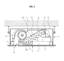
- FIG. 2 is a side cross-sectional view illustrating the indoor unit of the ceiling type air-conditioner in accordance with an embodiment of the disclosure.
- an indoor unit 1 of a ceiling type air-conditioner in accordance with an embodiment of the disclosure may be installed at a ceiling C of an indoor space.
- the indoor unit 1 may be installed to protrude from the ceiling C or may be suspended from the ceiling C.
- the indoor unit 1 may include a main body and a front panel 11.
- the main body may include a case 10, a heat exchanger 12 and a blowing fan 13.
- the front panel 11 may be disposed in front of the case 10 and may form a front exterior of the indoor unit 1.
- the heat exchanger 12 and the blowing fan 13 may be received in the case 10.
- the case 10 may be buried in the ceiling C or may be installed at the ceiling C.
- the heat exchanger 12 may be inclinedly installed in the case 10.
- a supporting part 14 which supports the heat exchanger 12 and also guides sucked air to the heat exchanger 12 may be provided under the heat exchanger 12.
- the blowing fan 13 may be disposed in front of the heat exchanger 12.
- the blowing fan 13 may be in the form of a tangential fan, for example.
- a motor (not shown) driving the blowing fan 13 may be further provided in the case 10.
- An inclined guide part 15 which guides the heat exchanger 12 so as to be installed inclinedly when the heat exchanger 12 is installed in the case 10 may be provided above the heat exchanger 12.
- a coupling member 150 which is coupled with a part of the heat exchanger 12 so as to fix the heat exchanger 12 may be provided at the inclined guide part 15. As shown in FIG. 2 , the inclined guide part 15 may be disposed between the heat exchanger 12 and the blowing fan 13. A hooking part 121 of the heat exchanger 12 may be hooked to the coupling member 150. The hooking part 121 may be provided at a side plate 120 attached to a side surface of the heat exchanger 12. A stopping part 16 which supports the side surface of the heat exchanger 12 so as to prevent leftward and rightward movement of the heat exchanger 12 may be provided at an upper inner surface of the case 10.
- An inlet port 2 and an outlet port 3 may be provided in front of the indoor unit 1. Air sucked in the main body through the inlet port 2 by the blowing fan 13 may be heat-exchanged at the heat exchanger 12 and then discharged to a room through the outlet port 3. Thus, air-conditioning or heating may be performed.
- the heat exchanger 12 may be inclined at an angle such that a lower portion of the heat exchanger 12 is closer to the outlet port 3 than the upper portion of the heat exchanger 12. Further, as shown in FIG. 2 , the heat exchanger 12 may be inclined at an angle such that the upper portion of the heat exchanger 12 is closer to the stopping part 16 than the lower portion of the heat exchanger 12.
- a suction grill 17 and a discharge blade 18 may be provided at the front panel 11.
- the suction grill 17 may be provided at a side of the inlet port.
- the suction grill 17 may be configured by aligning a plurality of ribs which are inclinedly arranged.
- the suction grill 17 may be provided to cover the inlet port 2 and thus prevent an inner side of the main body from being exposed through the inlet port 2, and also to allow indoor air to be sucked through the inlet port 2.
- the discharge blade 18 may be provided at a side of the outlet port 3.
- the discharge blade 18 may selectively cover the outlet port 3.
- the discharge blade 18 may be manufactured separately from the front panel 11 and then installed at the front panel 11.
- the discharge blade 18 may cover the outlet port 3 so as to prevent the inner side of the main body from being exposed through the outlet port 3.
- the outlet port 3 may be opened so that the air sucked through the inlet port 2 is discharged to the room through the outlet port 3.
- the discharge blade 18 may be hinged. When the indoor unit 1 is operated, the discharge blade 18 may be rotated around a hinge and thus may open the outlet port 3.
- the front panel 11 may be manufactured by injection-molding a resin.
- the front panel 11 may be manufactured by dual injection molding.
- the suction grill 17 may be manufactured to be formed integrally with the front panel 11.
- the front panel 11 may be manufactured by dual-injection-molding resins having different colors, textures and so on.
- the front panel 11 may be manufactured by dual-injection-molding a transparent resin and a colored resin.
- a primary injection-molded part of the front panel 11 is injection-molded with the transparent resin, and a secondary injection-molded part thereof is injection-molded using the colored resin, the secondary injection-molded part formed of the colored resin may be configured to be seen subtly.
- the front panel 11 may be manufactured by the dual injection molding of a combination of various resins, thereby providing beautiful designs corresponding to indoor interiors.
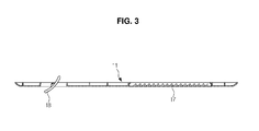
- FIG. 3 is a cross-sectional view illustrating a front panel of the indoor unit in accordance with an embodiment of the disclosure
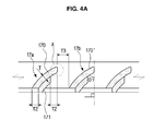
- FIG. 4A is a cross-sectional view in accordance with an embodiment of the disclosure
- FIG 4B is a cross-sectional view partially illustrating A of Fig 4A in accordance with an embodiment of the disclosure
- the suction grill 17 in accordance with an embodiment of the disclosure may be provided by inclinedly arranging the plurality of ribs.
- An extension direction of a cross section of the suction grill 17 may form a predetermined angle ⁇ 1 with respect to a vertical line which is perpendicular to the front panel 11.
- the angle ⁇ 1 formed between the extension direction of the cross section of the suction grill 17 and the vertical line to one surface of the front panel 11 may be 0° or more and 90° or less.
- the suction grill 17 may include the primary injection-molded part 170 and the secondary injection-molded part 171.
- the plurality of ribs may be arranged to be inclined in a manner similar to the heat exchanger 12. That is, the plurality of ribs may be inclined at an angle such that the upper portion of the plurality of ribs is closer to a side of the indoor unit 1 at which the stopping part 16 is disposed than the lower portion of the plurality of ribs.
- the plurality of ribs may be inclined at an angle such that a lower portion of the plurality of ribs is closer to a side of the indoor unit at which the outlet port 3 is disposed than the upper portion of the plurality of ribs.
- the plurality of ribs may have an inclined shape to be inclined in a first direction.
- the plurality of ribs may be inclined in a different direction, for example, a second direction which is opposite of the first direction.
- the ribs When inclined shapes of the plurality of the ribs are manufactured by the dual injection molding, the ribs may not be easily taken out of a mold upon a secondary injection molding process. Further, if sealing is not properly achieved upon the secondary injection molding process, a secondary injection solution may flow down to a side of the primary injection-molded part.
- the sealing should be achieved between the primary injection-molded part 170 and the secondary injection-molded part 171 in order to minimize a defect rate, and the injection molding should also be easily taken out of the mold.
- a sticking section T1 may be provided at a side surface of the rib forming the suction grill 17.
- the sticking section T1 may be provided at a side surface of the primary injection-molded part 170.
- the sticking section T1 may be a section fixed by a fixing device when the mold in which the primary injection-molded part 170 is received after a primary injection of the suction grill 17 is moved to a position for a secondary injection.
- the primary injection-molded part 170 may be fixed by the fixing device when being moved to the position for the secondary injection and thus prevented from being separated from the mold.
- the sticking section T1 may have a width of at least about 1 mm.
- the sticking section T1 may be provided to have a flat surface or a grade ⁇ 2 of about 5°.
- the sticking section T1 may be arranged to be inclined in a manner similar to the heat exchanger 12. That is, the sticking section T1 may be inclined at an angle such that the upper portion of the sticking section T1 is closer to a side of the indoor unit 1 at which the stopping part 16 is disposed than the lower portion of the sticking section T1. Similarly, the sticking section T1 may be inclined at an angle such that a lower portion of the sticking section T1 is closer to a side of the indoor unit at which the outlet port 3 is disposed than the upper portion of the sticking section T1.
- the sticking section T1 may be at an end of a rib.
- the sticking section T1 may be inclined relative to the extension direction of the rib, having an angle of inclination of about 5°.
- a sealing section T2 may be provided at the other (e.g., lower) side surface of the rib forming the suction grill 17.
- the sealing section T2 may be provided in a plane section, for example.
- the sealing section T2 may be provided at the mold corresponding to the other (e.g., upper) side surface of the primary injection-molded part 170, and thus a plurality of sealing sections T2 may be provided.
- the secondary injection-molded part 171 may be formed by injecting a secondary injection solution between the sealing sections T2.
- a sealing part of the mold may be located at the sealing section T2.
- the sealing part serves to air-tightly seal the side of the primary injection-molded part 170.
- the secondary injection solution may be prevented from flowing toward the primary injection-molded part 170 by the sealing part provided with the sealing section T2.
- a width of the sealing section T2 may be provided to have about 0.5 times a thickness T of the primary injection-molded part 170.
- a scraping section T3 may be provided between the adjacent ribs 17a and 17b of the suction grill.
- the adjacent ribs 17a and 17b of the suction grill are a first suction rib 17a and a second suction rib 17b
- one end of the first suction rib 17a which is primarily injected and the other end of the second suction rib 17b which is primarily injected may be formed to be spaced apart from each other by a distance corresponding to the scraping section T3.
- the scraping section T3 may have a width of about 5 mm or more. As the scraping section T3 is provided, the injection-molded ribs 17a and 17b of the suction grill may be easily taken out of the mold.
- Shapes corresponding to the sticking section T1, the sealing section T2 and the scraping section T3 may be provided at the mold by which the suction grill 17 is injection-molded.
- the sticking section T1 the primary injection-molded parts 170 and 170' may be prevented from being separated from the mold while being moved to the position for the second injection.
- the sealing section T2 the secondary injection solution may be prevented from flowing down to the primary injection-molded parts 170 and 170'.
- the scraping section T3 is provided between the adjacent injection-molded ribs 17a and 17b, the injection-molded ribs 17a and 17b of the suction grill may be easily taken out of the mold.
- the primary injection-molded part 170 and the secondary injection-molded part 171 may be formed to have a clear boundary at the suction grill 17.
- the secondary injection-molded part 171 may be disposed such that at least a portion of an outer circumferential edge borders at least a portion of an inner circumferential edge of the primary injection-molded part 170.
- the secondary injection-molded part 171 may be injection-molded of a material having a different color and texture from the primary injection-molded part 170. Since the front panel 11 may be manufactured by using a combination of various colors and textures, the front panel 11 may have various designs. Therefore, since the front panel 11 may be manufactured to correspond to the interiors of the indoor space in which the indoor unit 1 is installed, it is possible to improve customer satisfaction.
- the primary injection-molded part of the front panel 11 may be injection-molded with a transparent resin, and the secondary injection-molded part may be injection-molded using a colored resin.
- the primary injection-molded part of the front panel 11 may be injection-molded with a colored resin
- the secondary injection-molded part may be injection-molded using a transparent resin
- both the primary injection-molded part and the secondary injection-molded part of the front panel 11 may be injection-molded with a colored resin
- both the primary injection-molded part and the secondary injection-molded part of the front panel 11 may be injection-molded with a transparent resin.
- FIG. 5 is a flow chart illustrating a method of manufacturing the front panel of the indoor unit in accordance with an embodiment of the disclosure.
- a method of manufacturing the front panel of the indoor unit in accordance with an embodiment of the disclosure may include a process (S1) of injecting the primary injection solution capable of forming the primary injection-molded part 170 into the mold.
- a transparent resin solution may be injected into the mold so that the primary injection-molded part 170 is formed to be transparent.
- a process (S2) of cooling the primary injection solution injected into the mold for a predetermined period of time may be performed.
- a process (S3) of moving the mold to the position for the secondary injection may be performed.
- the primary injection-molded part 170 to form the suction grill 17 may be prevented from being separated from the mold.
- the secondary injection solution may be injected (S4).
- the secondary injection-molded part 171 may be formed of the colored resin.
- the secondary injection solution serving as a colored resin solution may be injected into the mold. At this time, the secondary injection solution may be prevented from being leaked toward the primary injection-molded part 170 by the sealing section T2.
- the secondary injection solution may be injected between a first sealing section T2 provided at a first side surface of the primary injection-molded part and a second sealing section T2 provided at a second side surface of the primary injection-molded part.
- a cooling process (S5) may be performed for a predetermined period of time.
- the front panel 11 may be taken out of (extracted from) the mold by using a taking-out (extracting) member (S6).
- the scraping section T3 is provided at the suction grill 17, the suction grill 17 may be easily taken out of the mold without any damage, even though the suction grill 17 is inclinedly formed. Therefore, by the above-mentioned method, the suction grill 17 of the front panel 11 may be easily manufactured through dual injection molding.
- the front panel of the indoor unit may be stably manufactured through dual injection molding so as to have the maximum yield. Since the front panel is manufactured by the dual injection molding, the indoor unit may have more various and beautiful designs.
Landscapes
- Engineering & Computer Science (AREA)
- Mechanical Engineering (AREA)
- Chemical & Material Sciences (AREA)
- Combustion & Propulsion (AREA)
- General Engineering & Computer Science (AREA)
- Manufacturing & Machinery (AREA)
- Physics & Mathematics (AREA)
- Thermal Sciences (AREA)
- Air Filters, Heat-Exchange Apparatuses, And Housings Of Air-Conditioning Units (AREA)
- Injection Moulding Of Plastics Or The Like (AREA)
Applications Claiming Priority (1)
| Application Number | Priority Date | Filing Date | Title |
|---|---|---|---|
| KR1020130138582A KR101880103B1 (ko) | 2013-11-14 | 2013-11-14 | 실내기의 전면패널 및 그의 제조방법 |
Publications (2)
| Publication Number | Publication Date |
|---|---|
| EP2876379A1 true EP2876379A1 (de) | 2015-05-27 |
| EP2876379B1 EP2876379B1 (de) | 2017-03-01 |
Family
ID=52020924
Family Applications (1)
| Application Number | Title | Priority Date | Filing Date |
|---|---|---|---|
| EP14193111.3A Not-in-force EP2876379B1 (de) | 2013-11-14 | 2014-11-13 | Frontpaneel einer Innenraumeinheit und Herstellungsverfahren dafür |
Country Status (5)
| Country | Link |
|---|---|
| US (1) | US20150133045A1 (de) |
| EP (1) | EP2876379B1 (de) |
| KR (1) | KR101880103B1 (de) |
| CN (2) | CN104633897B (de) |
| ES (1) | ES2625164T3 (de) |
Families Citing this family (5)
| Publication number | Priority date | Publication date | Assignee | Title |
|---|---|---|---|---|
| USD1017011S1 (en) * | 2021-12-09 | 2024-03-05 | Lg Electronics Inc. | Window air conditioner |
| USD1017007S1 (en) * | 2021-12-09 | 2024-03-05 | Lg Electronics Inc. | Window air conditioner |
| USD1017005S1 (en) * | 2021-12-09 | 2024-03-05 | Lg Electronics Inc. | Window air conditioner |
| USD1017010S1 (en) * | 2021-12-09 | 2024-03-05 | Lg Electronics Inc. | Window air conditioner |
| USD1017006S1 (en) * | 2021-12-09 | 2024-03-05 | Lg Electronics Inc. | Window air conditioner |
Citations (4)
| Publication number | Priority date | Publication date | Assignee | Title |
|---|---|---|---|---|
| EP1352774A2 (de) * | 2002-03-13 | 2003-10-15 | John McGavigan Limited | Bedientafel |
| WO2009096613A2 (en) * | 2008-01-30 | 2009-08-06 | Lg Electronics Inc. | Grill unit for air conditioner and manufacturing method for thereof |
| US20110047888A1 (en) * | 2005-08-31 | 2011-03-03 | Tapco International Corporation | Adjustable mounting bracket assembly for exterior siding |
| US20110181066A1 (en) * | 2010-01-22 | 2011-07-28 | Dr. Ing. H.C.F. Porsche Aktiengesellschaft | One-piece covering element |
Family Cites Families (40)
| Publication number | Priority date | Publication date | Assignee | Title |
|---|---|---|---|---|
| US3628443A (en) * | 1969-12-09 | 1971-12-21 | Mc Graw Edison Co | Adjustable air-direction means for a conditioner |
| US4103601A (en) * | 1976-10-22 | 1978-08-01 | Lloyd Giddis Dayus | Air grille components and air grille therefrom |
| US4419300A (en) * | 1980-03-03 | 1983-12-06 | General Texas Corporation | Non-corrosive, non-staining evaporative cooler |
| US4309365A (en) * | 1980-03-03 | 1982-01-05 | David Van Ness | Non-corrosive, non-staining evaporative cooler |
| JP2507330B2 (ja) * | 1986-06-26 | 1996-06-12 | 株式会社東芝 | 空気調和機等の前面パネルの成形方法 |
| US4911066A (en) * | 1988-04-18 | 1990-03-27 | Carew Dean F S | Fitted ventilation louver |
| JP3030665B2 (ja) * | 1991-06-07 | 2000-04-10 | 森六株式会社 | 空調用吹出口装置の二重射出成形方法 |
| JPH06838A (ja) * | 1992-06-17 | 1994-01-11 | Nissha Printing Co Ltd | グリルを有する絵付成形品の製造方法 |
| US5251461A (en) * | 1992-09-18 | 1993-10-12 | Carrier Corporation | Grille for packaged terminal air conditioner |
| US5349799A (en) * | 1993-08-25 | 1994-09-27 | Mid-America Building Products Corporation | Plastic gable vent |
| US5856210A (en) * | 1995-04-06 | 1999-01-05 | Hi-Z Technology, Inc. | Method for fabricating a thermoelectric module with gapless eggcrate |
| CH692572A8 (de) * | 1996-07-10 | 2002-10-15 | Sarnatech Bnl Ltd | WELLE, AUCH ACHSE ODER ROLLKöRPER GENANNT. |
| ATE356045T1 (de) * | 1999-11-17 | 2007-03-15 | Reckitt Benckiser Uk Ltd | Spritzgegossener wasserlöslicher behälter |
| KR100366218B1 (ko) * | 2000-02-12 | 2003-01-09 | 주식회사 새샘 | 횡형 사출기에 있어서, 각종 식품 용기의 뚜껑제품 성형방법 및 이 방법에 의해 제조되는 뚜껑제품 |
| US6302785B1 (en) * | 2000-06-12 | 2001-10-16 | Headrick Building Products, Inc. | Foundation vent with improved net free ventilation area |
| TWI358602B (en) * | 2003-06-02 | 2012-02-21 | Seiko Epson Corp | Projection device and vent screens |
| WO2005006903A1 (en) * | 2003-07-16 | 2005-01-27 | Soo-Hoo Beak | Injection molded phylon midsole |
| JP3642064B2 (ja) * | 2003-09-01 | 2005-04-27 | ダイキン工業株式会社 | 空気調和機の室内機およびその製造方法 |
| AR041755A4 (es) * | 2003-11-03 | 2005-05-26 | Moreno Oscar Adolfo | Rejilla de aire descartable |
| US7255189B2 (en) * | 2004-06-18 | 2007-08-14 | Cnh America Llc | Radiator mounting system |
| CN101341365A (zh) * | 2005-11-14 | 2009-01-07 | 韦巴斯托股份公司 | 通风格栅框架、通风格栅条和通风格栅以及用于生产通风格栅的方法 |
| JP4618807B2 (ja) * | 2006-06-07 | 2011-01-26 | 株式会社エンプラス | 射出成形樹脂歯車 |
| JP2007331204A (ja) * | 2006-06-14 | 2007-12-27 | Oshima Denki Seisakusho:Kk | 成形体および成形体の製造方法 |
| JP5194408B2 (ja) * | 2006-08-30 | 2013-05-08 | ダイキン工業株式会社 | 空気調和装置の意匠パネルを製造する方法および空気調和装置の意匠パネル |
| US20100015905A1 (en) * | 2007-03-07 | 2010-01-21 | Sine Kon Hu | Airflow boosting assembly for a forced air circulation and delivery system |
| DE102007026385A1 (de) * | 2007-06-06 | 2008-12-24 | Trw Automotive Electronics & Components Gmbh | Entlüftungsvorrichtung für ein Kraftfahrzeug sowie Formwerkzeug und Verfahren zur Herstellung der Entlüftungsvorrichtung |
| JP2009051121A (ja) * | 2007-08-28 | 2009-03-12 | Suzuki Motor Corp | インモールド成形方法 |
| US20090130970A1 (en) * | 2007-11-21 | 2009-05-21 | Corey Scott Jacak | Exhaust fan and method of operating the same |
| JP2009162434A (ja) | 2008-01-08 | 2009-07-23 | Daikin Ind Ltd | 空気調和機用格子、空気調和機および空気調和機用格子の製造方法 |
| JP5299967B2 (ja) * | 2008-08-06 | 2013-09-25 | 株式会社エンプラス | 射出成形樹脂フェースギヤ |
| US8292708B2 (en) * | 2009-01-26 | 2012-10-23 | Elima-Draft Incorporated | Magnetic register cover |
| KR20100107182A (ko) * | 2009-03-25 | 2010-10-05 | 삼성전자주식회사 | 사출방법 |
| KR101640411B1 (ko) * | 2009-10-16 | 2016-07-18 | 엘지전자 주식회사 | 공기조화기 |
| US9011746B2 (en) * | 2012-02-07 | 2015-04-21 | Caco Pacific Corporation | Mold and method for molding parts requiring multiple mold inputs |
| US8931828B2 (en) * | 2012-11-12 | 2015-01-13 | GM Global Technology Operations LLC | Grill opening reinforcement assembly |
| EP2772579B1 (de) * | 2013-01-25 | 2016-11-02 | Samsung Electronics Co., Ltd | Waschmaschine |
| US20140342653A1 (en) * | 2013-05-17 | 2014-11-20 | Noll/Norwesco Llc | Rim joist vent |
| US20150031282A1 (en) * | 2013-07-24 | 2015-01-29 | Joseph Peter Nagan | Low-Resistance, Discharge-Vent Soffit Frame |
| KR102168584B1 (ko) * | 2013-11-12 | 2020-10-22 | 삼성전자주식회사 | 천장형 에어컨 실내기 |
| KR101662377B1 (ko) * | 2014-01-27 | 2016-10-04 | 엘지전자 주식회사 | 공기조화기의 실내기 |
-
2013
- 2013-11-14 KR KR1020130138582A patent/KR101880103B1/ko not_active Expired - Fee Related
-
2014
- 2014-11-13 US US14/540,594 patent/US20150133045A1/en not_active Abandoned
- 2014-11-13 EP EP14193111.3A patent/EP2876379B1/de not_active Not-in-force
- 2014-11-13 ES ES14193111.3T patent/ES2625164T3/es active Active
- 2014-11-14 CN CN201410648551.9A patent/CN104633897B/zh not_active Expired - Fee Related
- 2014-11-14 CN CN201710542330.7A patent/CN107246721B/zh not_active Expired - Fee Related
Patent Citations (4)
| Publication number | Priority date | Publication date | Assignee | Title |
|---|---|---|---|---|
| EP1352774A2 (de) * | 2002-03-13 | 2003-10-15 | John McGavigan Limited | Bedientafel |
| US20110047888A1 (en) * | 2005-08-31 | 2011-03-03 | Tapco International Corporation | Adjustable mounting bracket assembly for exterior siding |
| WO2009096613A2 (en) * | 2008-01-30 | 2009-08-06 | Lg Electronics Inc. | Grill unit for air conditioner and manufacturing method for thereof |
| US20110181066A1 (en) * | 2010-01-22 | 2011-07-28 | Dr. Ing. H.C.F. Porsche Aktiengesellschaft | One-piece covering element |
Also Published As
| Publication number | Publication date |
|---|---|
| KR20150056121A (ko) | 2015-05-26 |
| KR101880103B1 (ko) | 2018-07-23 |
| CN107246721A (zh) | 2017-10-13 |
| ES2625164T3 (es) | 2017-07-18 |
| CN104633897B (zh) | 2019-06-11 |
| EP2876379B1 (de) | 2017-03-01 |
| US20150133045A1 (en) | 2015-05-14 |
| CN104633897A (zh) | 2015-05-20 |
| CN107246721B (zh) | 2019-04-05 |
Similar Documents
| Publication | Publication Date | Title |
|---|---|---|
| EP2876379B1 (de) | Frontpaneel einer Innenraumeinheit und Herstellungsverfahren dafür | |
| US9976758B2 (en) | Indoor unit of air conditioning device with insulated air passage | |
| KR100671108B1 (ko) | 공기 조화기의 실내기 | |
| KR20060017040A (ko) | 스탠드형 에어콘 실내기 | |
| JP2018159524A (ja) | 一体型空気調和機 | |
| KR102480314B1 (ko) | 드레인호스 및 이를 포함하는 공기조화기 | |
| CN109696001A (zh) | 冷藏送风总成 | |
| CN108758864A (zh) | 一种空调室外机及其除霜方法 | |
| CN209840295U (zh) | 空调机的室外机 | |
| KR20150034641A (ko) | 제습 장치 | |
| US11566794B2 (en) | Air conditioner | |
| JP5479547B2 (ja) | 空調室内機 | |
| US20130160475A1 (en) | Refrigerated Case Defrost Water Drain | |
| KR102124929B1 (ko) | 공기조화기를 위한 터보팬 | |
| CN101655263B (zh) | 室内埋入型热源机 | |
| CN213630681U (zh) | 空调器 | |
| JP4189253B2 (ja) | 冷却貯蔵庫 | |
| EP2600075B1 (de) | Formteil und Herstellungsverfahren | |
| US11747026B2 (en) | Outdoor unit for air conditioner | |
| CN109883105A (zh) | 一种冷柜 | |
| KR101754080B1 (ko) | 차량용 공조장치 | |
| CN103335472B (zh) | 冰箱及其回风道 | |
| KR101474014B1 (ko) | 공기조화기 실내기의 드레인팬 | |
| KR101328531B1 (ko) | 에어컨 및 냉동장치용 실외기의 전면커버 | |
| CN103047813B (zh) | 冰箱及其安装方法 |
Legal Events
| Date | Code | Title | Description |
|---|---|---|---|
| PUAI | Public reference made under article 153(3) epc to a published international application that has entered the european phase |
Free format text: ORIGINAL CODE: 0009012 |
|
| 17P | Request for examination filed |
Effective date: 20141113 |
|
| AK | Designated contracting states |
Kind code of ref document: A1 Designated state(s): AL AT BE BG CH CY CZ DE DK EE ES FI FR GB GR HR HU IE IS IT LI LT LU LV MC MK MT NL NO PL PT RO RS SE SI SK SM TR |
|
| AX | Request for extension of the european patent |
Extension state: BA ME |
|
| R17P | Request for examination filed (corrected) |
Effective date: 20151125 |
|
| RBV | Designated contracting states (corrected) |
Designated state(s): AL AT BE BG CH CY CZ DE DK EE ES FI FR GB GR HR HU IE IS IT LI LT LU LV MC MK MT NL NO PL PT RO RS SE SI SK SM TR |
|
| GRAP | Despatch of communication of intention to grant a patent |
Free format text: ORIGINAL CODE: EPIDOSNIGR1 |
|
| RIC1 | Information provided on ipc code assigned before grant |
Ipc: F24F 13/08 20060101AFI20160413BHEP Ipc: B29L 31/18 20060101ALI20160413BHEP Ipc: F24F 13/20 20060101ALI20160413BHEP Ipc: B29C 45/00 20060101ALI20160413BHEP Ipc: F25D 23/00 20060101ALI20160413BHEP Ipc: B29C 45/16 20060101ALI20160413BHEP |
|
| INTG | Intention to grant announced |
Effective date: 20160502 |
|
| GRAJ | Information related to disapproval of communication of intention to grant by the applicant or resumption of examination proceedings by the epo deleted |
Free format text: ORIGINAL CODE: EPIDOSDIGR1 |
|
| GRAP | Despatch of communication of intention to grant a patent |
Free format text: ORIGINAL CODE: EPIDOSNIGR1 |
|
| INTC | Intention to grant announced (deleted) | ||
| INTG | Intention to grant announced |
Effective date: 20161004 |
|
| STAA | Information on the status of an ep patent application or granted ep patent |
Free format text: STATUS: GRANT OF PATENT IS INTENDED |
|
| GRAS | Grant fee paid |
Free format text: ORIGINAL CODE: EPIDOSNIGR3 |
|
| GRAA | (expected) grant |
Free format text: ORIGINAL CODE: 0009210 |
|
| STAA | Information on the status of an ep patent application or granted ep patent |
Free format text: STATUS: THE PATENT HAS BEEN GRANTED |
|
| AK | Designated contracting states |
Kind code of ref document: B1 Designated state(s): AL AT BE BG CH CY CZ DE DK EE ES FI FR GB GR HR HU IE IS IT LI LT LU LV MC MK MT NL NO PL PT RO RS SE SI SK SM TR |
|
| REG | Reference to a national code |
Ref country code: GB Ref legal event code: FG4D |
|
| REG | Reference to a national code |
Ref country code: CH Ref legal event code: EP Ref country code: AT Ref legal event code: REF Ref document number: 871852 Country of ref document: AT Kind code of ref document: T Effective date: 20170315 |
|
| REG | Reference to a national code |
Ref country code: IE Ref legal event code: FG4D |
|
| REG | Reference to a national code |
Ref country code: DE Ref legal event code: R096 Ref document number: 602014007086 Country of ref document: DE |
|
| REG | Reference to a national code |
Ref country code: NL Ref legal event code: MP Effective date: 20170301 |
|
| REG | Reference to a national code |
Ref country code: LT Ref legal event code: MG4D |
|
| REG | Reference to a national code |
Ref country code: AT Ref legal event code: MK05 Ref document number: 871852 Country of ref document: AT Kind code of ref document: T Effective date: 20170301 |
|
| REG | Reference to a national code |
Ref country code: ES Ref legal event code: FG2A Ref document number: 2625164 Country of ref document: ES Kind code of ref document: T3 Effective date: 20170718 |
|
| PG25 | Lapsed in a contracting state [announced via postgrant information from national office to epo] |
Ref country code: FI Free format text: LAPSE BECAUSE OF FAILURE TO SUBMIT A TRANSLATION OF THE DESCRIPTION OR TO PAY THE FEE WITHIN THE PRESCRIBED TIME-LIMIT Effective date: 20170301 Ref country code: GR Free format text: LAPSE BECAUSE OF FAILURE TO SUBMIT A TRANSLATION OF THE DESCRIPTION OR TO PAY THE FEE WITHIN THE PRESCRIBED TIME-LIMIT Effective date: 20170602 Ref country code: HR Free format text: LAPSE BECAUSE OF FAILURE TO SUBMIT A TRANSLATION OF THE DESCRIPTION OR TO PAY THE FEE WITHIN THE PRESCRIBED TIME-LIMIT Effective date: 20170301 Ref country code: NO Free format text: LAPSE BECAUSE OF FAILURE TO SUBMIT A TRANSLATION OF THE DESCRIPTION OR TO PAY THE FEE WITHIN THE PRESCRIBED TIME-LIMIT Effective date: 20170601 Ref country code: LT Free format text: LAPSE BECAUSE OF FAILURE TO SUBMIT A TRANSLATION OF THE DESCRIPTION OR TO PAY THE FEE WITHIN THE PRESCRIBED TIME-LIMIT Effective date: 20170301 |
|
| PG25 | Lapsed in a contracting state [announced via postgrant information from national office to epo] |
Ref country code: RS Free format text: LAPSE BECAUSE OF FAILURE TO SUBMIT A TRANSLATION OF THE DESCRIPTION OR TO PAY THE FEE WITHIN THE PRESCRIBED TIME-LIMIT Effective date: 20170301 Ref country code: AT Free format text: LAPSE BECAUSE OF FAILURE TO SUBMIT A TRANSLATION OF THE DESCRIPTION OR TO PAY THE FEE WITHIN THE PRESCRIBED TIME-LIMIT Effective date: 20170301 Ref country code: SE Free format text: LAPSE BECAUSE OF FAILURE TO SUBMIT A TRANSLATION OF THE DESCRIPTION OR TO PAY THE FEE WITHIN THE PRESCRIBED TIME-LIMIT Effective date: 20170301 Ref country code: LV Free format text: LAPSE BECAUSE OF FAILURE TO SUBMIT A TRANSLATION OF THE DESCRIPTION OR TO PAY THE FEE WITHIN THE PRESCRIBED TIME-LIMIT Effective date: 20170301 Ref country code: BG Free format text: LAPSE BECAUSE OF FAILURE TO SUBMIT A TRANSLATION OF THE DESCRIPTION OR TO PAY THE FEE WITHIN THE PRESCRIBED TIME-LIMIT Effective date: 20170601 |
|
| PG25 | Lapsed in a contracting state [announced via postgrant information from national office to epo] |
Ref country code: NL Free format text: LAPSE BECAUSE OF FAILURE TO SUBMIT A TRANSLATION OF THE DESCRIPTION OR TO PAY THE FEE WITHIN THE PRESCRIBED TIME-LIMIT Effective date: 20170301 |
|
| PG25 | Lapsed in a contracting state [announced via postgrant information from national office to epo] |
Ref country code: EE Free format text: LAPSE BECAUSE OF FAILURE TO SUBMIT A TRANSLATION OF THE DESCRIPTION OR TO PAY THE FEE WITHIN THE PRESCRIBED TIME-LIMIT Effective date: 20170301 Ref country code: RO Free format text: LAPSE BECAUSE OF FAILURE TO SUBMIT A TRANSLATION OF THE DESCRIPTION OR TO PAY THE FEE WITHIN THE PRESCRIBED TIME-LIMIT Effective date: 20170301 Ref country code: CZ Free format text: LAPSE BECAUSE OF FAILURE TO SUBMIT A TRANSLATION OF THE DESCRIPTION OR TO PAY THE FEE WITHIN THE PRESCRIBED TIME-LIMIT Effective date: 20170301 Ref country code: SK Free format text: LAPSE BECAUSE OF FAILURE TO SUBMIT A TRANSLATION OF THE DESCRIPTION OR TO PAY THE FEE WITHIN THE PRESCRIBED TIME-LIMIT Effective date: 20170301 |
|
| PG25 | Lapsed in a contracting state [announced via postgrant information from national office to epo] |
Ref country code: SM Free format text: LAPSE BECAUSE OF FAILURE TO SUBMIT A TRANSLATION OF THE DESCRIPTION OR TO PAY THE FEE WITHIN THE PRESCRIBED TIME-LIMIT Effective date: 20170301 Ref country code: IS Free format text: LAPSE BECAUSE OF FAILURE TO SUBMIT A TRANSLATION OF THE DESCRIPTION OR TO PAY THE FEE WITHIN THE PRESCRIBED TIME-LIMIT Effective date: 20170701 Ref country code: PL Free format text: LAPSE BECAUSE OF FAILURE TO SUBMIT A TRANSLATION OF THE DESCRIPTION OR TO PAY THE FEE WITHIN THE PRESCRIBED TIME-LIMIT Effective date: 20170301 Ref country code: PT Free format text: LAPSE BECAUSE OF FAILURE TO SUBMIT A TRANSLATION OF THE DESCRIPTION OR TO PAY THE FEE WITHIN THE PRESCRIBED TIME-LIMIT Effective date: 20170703 |
|
| REG | Reference to a national code |
Ref country code: DE Ref legal event code: R097 Ref document number: 602014007086 Country of ref document: DE |
|
| PLBE | No opposition filed within time limit |
Free format text: ORIGINAL CODE: 0009261 |
|
| STAA | Information on the status of an ep patent application or granted ep patent |
Free format text: STATUS: NO OPPOSITION FILED WITHIN TIME LIMIT |
|
| PG25 | Lapsed in a contracting state [announced via postgrant information from national office to epo] |
Ref country code: DK Free format text: LAPSE BECAUSE OF FAILURE TO SUBMIT A TRANSLATION OF THE DESCRIPTION OR TO PAY THE FEE WITHIN THE PRESCRIBED TIME-LIMIT Effective date: 20170301 |
|
| 26N | No opposition filed |
Effective date: 20171204 |
|
| PG25 | Lapsed in a contracting state [announced via postgrant information from national office to epo] |
Ref country code: SI Free format text: LAPSE BECAUSE OF FAILURE TO SUBMIT A TRANSLATION OF THE DESCRIPTION OR TO PAY THE FEE WITHIN THE PRESCRIBED TIME-LIMIT Effective date: 20170301 |
|
| REG | Reference to a national code |
Ref country code: DE Ref legal event code: R119 Ref document number: 602014007086 Country of ref document: DE |
|
| PG25 | Lapsed in a contracting state [announced via postgrant information from national office to epo] |
Ref country code: MC Free format text: LAPSE BECAUSE OF FAILURE TO SUBMIT A TRANSLATION OF THE DESCRIPTION OR TO PAY THE FEE WITHIN THE PRESCRIBED TIME-LIMIT Effective date: 20170301 |
|
| PG25 | Lapsed in a contracting state [announced via postgrant information from national office to epo] |
Ref country code: LI Free format text: LAPSE BECAUSE OF NON-PAYMENT OF DUE FEES Effective date: 20171130 Ref country code: CH Free format text: LAPSE BECAUSE OF NON-PAYMENT OF DUE FEES Effective date: 20171130 |
|
| PG25 | Lapsed in a contracting state [announced via postgrant information from national office to epo] |
Ref country code: LU Free format text: LAPSE BECAUSE OF NON-PAYMENT OF DUE FEES Effective date: 20171113 |
|
| REG | Reference to a national code |
Ref country code: FR Ref legal event code: ST Effective date: 20180731 Ref country code: BE Ref legal event code: MM Effective date: 20171130 |
|
| REG | Reference to a national code |
Ref country code: IE Ref legal event code: MM4A |
|
| PG25 | Lapsed in a contracting state [announced via postgrant information from national office to epo] |
Ref country code: MT Free format text: LAPSE BECAUSE OF NON-PAYMENT OF DUE FEES Effective date: 20171113 |
|
| PG25 | Lapsed in a contracting state [announced via postgrant information from national office to epo] |
Ref country code: DE Free format text: LAPSE BECAUSE OF NON-PAYMENT OF DUE FEES Effective date: 20180602 Ref country code: IE Free format text: LAPSE BECAUSE OF NON-PAYMENT OF DUE FEES Effective date: 20171113 Ref country code: FR Free format text: LAPSE BECAUSE OF NON-PAYMENT OF DUE FEES Effective date: 20171130 |
|
| PG25 | Lapsed in a contracting state [announced via postgrant information from national office to epo] |
Ref country code: BE Free format text: LAPSE BECAUSE OF NON-PAYMENT OF DUE FEES Effective date: 20171130 |
|
| PG25 | Lapsed in a contracting state [announced via postgrant information from national office to epo] |
Ref country code: HU Free format text: LAPSE BECAUSE OF FAILURE TO SUBMIT A TRANSLATION OF THE DESCRIPTION OR TO PAY THE FEE WITHIN THE PRESCRIBED TIME-LIMIT; INVALID AB INITIO Effective date: 20141113 |
|
| PG25 | Lapsed in a contracting state [announced via postgrant information from national office to epo] |
Ref country code: CY Free format text: LAPSE BECAUSE OF FAILURE TO SUBMIT A TRANSLATION OF THE DESCRIPTION OR TO PAY THE FEE WITHIN THE PRESCRIBED TIME-LIMIT Effective date: 20170301 |
|
| PG25 | Lapsed in a contracting state [announced via postgrant information from national office to epo] |
Ref country code: MK Free format text: LAPSE BECAUSE OF FAILURE TO SUBMIT A TRANSLATION OF THE DESCRIPTION OR TO PAY THE FEE WITHIN THE PRESCRIBED TIME-LIMIT Effective date: 20170301 |
|
| PG25 | Lapsed in a contracting state [announced via postgrant information from national office to epo] |
Ref country code: TR Free format text: LAPSE BECAUSE OF FAILURE TO SUBMIT A TRANSLATION OF THE DESCRIPTION OR TO PAY THE FEE WITHIN THE PRESCRIBED TIME-LIMIT Effective date: 20170301 |
|
| PG25 | Lapsed in a contracting state [announced via postgrant information from national office to epo] |
Ref country code: AL Free format text: LAPSE BECAUSE OF FAILURE TO SUBMIT A TRANSLATION OF THE DESCRIPTION OR TO PAY THE FEE WITHIN THE PRESCRIBED TIME-LIMIT Effective date: 20170301 |
|
| PGFP | Annual fee paid to national office [announced via postgrant information from national office to epo] |
Ref country code: GB Payment date: 20201012 Year of fee payment: 7 Ref country code: ES Payment date: 20201210 Year of fee payment: 7 Ref country code: IT Payment date: 20201113 Year of fee payment: 7 |
|
| GBPC | Gb: european patent ceased through non-payment of renewal fee |
Effective date: 20211113 |
|
| PG25 | Lapsed in a contracting state [announced via postgrant information from national office to epo] |
Ref country code: GB Free format text: LAPSE BECAUSE OF NON-PAYMENT OF DUE FEES Effective date: 20211113 |
|
| PG25 | Lapsed in a contracting state [announced via postgrant information from national office to epo] |
Ref country code: IT Free format text: LAPSE BECAUSE OF NON-PAYMENT OF DUE FEES Effective date: 20211113 |
|
| REG | Reference to a national code |
Ref country code: ES Ref legal event code: FD2A Effective date: 20230217 |
|
| PG25 | Lapsed in a contracting state [announced via postgrant information from national office to epo] |
Ref country code: ES Free format text: LAPSE BECAUSE OF NON-PAYMENT OF DUE FEES Effective date: 20211114 |