EP2886784B1 - Dispositif de blindage pour fenêtre et procédé associé - Google Patents
Dispositif de blindage pour fenêtre et procédé associé Download PDFInfo
- Publication number
- EP2886784B1 EP2886784B1 EP14196204.3A EP14196204A EP2886784B1 EP 2886784 B1 EP2886784 B1 EP 2886784B1 EP 14196204 A EP14196204 A EP 14196204A EP 2886784 B1 EP2886784 B1 EP 2886784B1
- Authority
- EP
- European Patent Office
- Prior art keywords
- free end
- position indicator
- screening device
- longitudinal position
- screen
- Prior art date
- Legal status (The legal status is an assumption and is not a legal conclusion. Google has not performed a legal analysis and makes no representation as to the accuracy of the status listed.)
- Active
Links
Images



Classifications
-
- E—FIXED CONSTRUCTIONS
- E06—DOORS, WINDOWS, SHUTTERS, OR ROLLER BLINDS IN GENERAL; LADDERS
- E06B—FIXED OR MOVABLE CLOSURES FOR OPENINGS IN BUILDINGS, VEHICLES, FENCES OR LIKE ENCLOSURES IN GENERAL, e.g. DOORS, WINDOWS, BLINDS, GATES
- E06B9/00—Screening or protective devices for wall or similar openings, with or without operating or securing mechanisms; Closures of similar construction
- E06B9/56—Operating, guiding or securing devices or arrangements for roll-type closures; Spring drums; Tape drums; Counterweighting arrangements therefor
- E06B9/80—Safety measures against dropping or unauthorised opening; Braking or immobilising devices; Devices for limiting unrolling
- E06B9/82—Safety measures against dropping or unauthorised opening; Braking or immobilising devices; Devices for limiting unrolling automatic
- E06B9/88—Safety measures against dropping or unauthorised opening; Braking or immobilising devices; Devices for limiting unrolling automatic for limiting unrolling
-
- E—FIXED CONSTRUCTIONS
- E06—DOORS, WINDOWS, SHUTTERS, OR ROLLER BLINDS IN GENERAL; LADDERS
- E06B—FIXED OR MOVABLE CLOSURES FOR OPENINGS IN BUILDINGS, VEHICLES, FENCES OR LIKE ENCLOSURES IN GENERAL, e.g. DOORS, WINDOWS, BLINDS, GATES
- E06B9/00—Screening or protective devices for wall or similar openings, with or without operating or securing mechanisms; Closures of similar construction
- E06B9/56—Operating, guiding or securing devices or arrangements for roll-type closures; Spring drums; Tape drums; Counterweighting arrangements therefor
- E06B9/80—Safety measures against dropping or unauthorised opening; Braking or immobilising devices; Devices for limiting unrolling
- E06B9/82—Safety measures against dropping or unauthorised opening; Braking or immobilising devices; Devices for limiting unrolling automatic
- E06B9/90—Safety measures against dropping or unauthorised opening; Braking or immobilising devices; Devices for limiting unrolling automatic for immobilising the closure member in various chosen positions
-
- E—FIXED CONSTRUCTIONS
- E06—DOORS, WINDOWS, SHUTTERS, OR ROLLER BLINDS IN GENERAL; LADDERS
- E06B—FIXED OR MOVABLE CLOSURES FOR OPENINGS IN BUILDINGS, VEHICLES, FENCES OR LIKE ENCLOSURES IN GENERAL, e.g. DOORS, WINDOWS, BLINDS, GATES
- E06B9/00—Screening or protective devices for wall or similar openings, with or without operating or securing mechanisms; Closures of similar construction
- E06B9/56—Operating, guiding or securing devices or arrangements for roll-type closures; Spring drums; Tape drums; Counterweighting arrangements therefor
- E06B9/68—Operating devices or mechanisms, e.g. with electric drive
- E06B2009/6809—Control
- E06B2009/6818—Control using sensors
-
- E—FIXED CONSTRUCTIONS
- E06—DOORS, WINDOWS, SHUTTERS, OR ROLLER BLINDS IN GENERAL; LADDERS
- E06B—FIXED OR MOVABLE CLOSURES FOR OPENINGS IN BUILDINGS, VEHICLES, FENCES OR LIKE ENCLOSURES IN GENERAL, e.g. DOORS, WINDOWS, BLINDS, GATES
- E06B9/00—Screening or protective devices for wall or similar openings, with or without operating or securing mechanisms; Closures of similar construction
- E06B9/56—Operating, guiding or securing devices or arrangements for roll-type closures; Spring drums; Tape drums; Counterweighting arrangements therefor
- E06B9/68—Operating devices or mechanisms, e.g. with electric drive
- E06B2009/6809—Control
- E06B2009/6818—Control using sensors
- E06B2009/6845—Control using sensors sensing position
-
- E—FIXED CONSTRUCTIONS
- E06—DOORS, WINDOWS, SHUTTERS, OR ROLLER BLINDS IN GENERAL; LADDERS
- E06B—FIXED OR MOVABLE CLOSURES FOR OPENINGS IN BUILDINGS, VEHICLES, FENCES OR LIKE ENCLOSURES IN GENERAL, e.g. DOORS, WINDOWS, BLINDS, GATES
- E06B9/00—Screening or protective devices for wall or similar openings, with or without operating or securing mechanisms; Closures of similar construction
- E06B9/56—Operating, guiding or securing devices or arrangements for roll-type closures; Spring drums; Tape drums; Counterweighting arrangements therefor
- E06B9/68—Operating devices or mechanisms, e.g. with electric drive
- E06B2009/6809—Control
- E06B2009/689—Control using end switches
Definitions
- the present disclosure relates to screening devices for screening a window, and more particularly to a screening device with a screen with an adjustable length in which the position of the free end of the screen can be controlled with an electric drive.
- the disclosure also relates to a method for controlling the position of the free end of a screen of a screening device for screening a window.
- EP 0 845 572 A1 discloses a device for controlling and actuating a venetian blind in a double-glazing unit of the type constituted by a rectangular frame which supports at least two panes which are mutually parallel and spaced so as to form a chamber isolated from the outside and inside which chamber the venetian blind is accommodated and moved.
- the venetian blind is moved by means of an electric motor.
- the device comprises at least one permanent magnet which is arranged on a bottom element of the venetian blind and at least one sensor which is fixed to the frame of the double-glazing unit in a specific position in order to signal that the venetian blind has passed and/or has reached the position of the sensor.
- This device has the drawback that only a very limited number of positions for the venetian blind may be obtained since for each position in which it may be desired to position the venetian blind a sensor must be provided.
- a sensor in case a high degree of freedom in choice of positions for the screening arrangement is desired a correspondingly high number of sensors would be needed.
- the construction with a large number of magnets would be rather complicated and expensive.
- Another drawback lies in the arrangement of the fixed sensors on the frame of the double-glazing unit which may cause the sensors to form an obstruction or even be subjected to damage e.g. when cleaning the window, and is furthermore, this solution aesthetically unappealing.
- a roller blind material is wound on a spindle rotated by an electric drive motor.
- the power supply for the electric drive motor is controlled by sensors positioned at each end of the required blind movement.
- the blind material is wound on a shaft, contained in a housing and driven by the electric drive motor.
- a rod forms the lower edge of the blind. Rotation of the shaft in one direction lowers the blind to a point and rotation in the other direction raises it to a point. Magnets in one end of the rod activate reed switches at the end positions of the blind to switch off the electric drive motor.
- a screening device for screening a window comprising a screen with a variable length, a fixed width between two edges of the screen and with a positionable free end, the longitudinal position of the free end determining the length of the screen, an electric drive is operably connected to the screen for adjusting the longitudinal position the free end, an elongated guide member parallel with the two edges and arranged adjacent to one of the two esges, a position indicator for manually indicting a desired longitudinal position of the free end, the longitudinal position of the position indicator being freely manually adjustable by an operator to any longitudinal position along the elongated guide element, a sensor arrangement configured for detecting a difference between the actual longitudinal position of the free end and the actual longitudinal position of the position indicator, a circuit or processor connected to the sensor arrangement, the circuit or processor being configured to operate the electric drive with the aim to reduce the detected difference between the actual longitudinal position of the free end and the actual longitudinal position of the position indicator.
- a window screening device that has an inexpensive, simple and robust user interface for manually adjusting the position of the free end of the screen, thereby adjusting the length of the screen and the area of the window covered by the screen.
- the provision of a manually freely adjustable position indicating element and arrangement that ensures that the free end of the screen follows the position of the position indicating element in a slave like manner provides for an intuitive user interface.
- This new user interface can be used in addition to a remote control that is configured to adjust the position of the screen.
- the device allows for free positioning the free end of the screen anywhere between the completely retracted and completely extended position of the screen
- the circuit or processor is configured to control the longitudinal position of the free end as a slave of the longitudinal position of the position indicator.
- the sensor arrangement is configured to detect the direction of the detected difference in longitudinal position between the actual longitudinal position of the free end and the actual longitudinal position of the position indicator.
- the process or control circuit is able to determine in which direction to move the free end of the screen by means of the electric drive.
- the sensor arrangement and the circuit or processor are arranged to form a closed loop to control the longitudinal position of the free end with the aim to minimize the detected difference in longitudinal position between the actual longitudinal position of the free end and the actual longitudinal position of the position indicator.
- the position indicator is disposed on the elongated guide member.
- the position indicator is slidably positionable along the elongated guide member.
- the screening device further comprises two parallel spaced rails for guiding the two edges of the screen.
- the provisional guide rails that guide the size of the screen allows the screen to be used in non-vertical applications.
- the elongated guide member is formed by one of the parallel spaced rails.
- the sensor arrangement comprises a sensor component at the free end and/or a sensor component at the position indicator.
- the position indicator comprises a magnet or a magnetic component.
- the at least one sensor element is any one of: a position sensor, an inductive sensor, a Reed sensor and a Hall sensor.
- the position indicator is arranged detachably on one of the two side rails.
- the position indicator is releasably coupled to the free edge so that the position indicator moves in unison with the free edge when the free end moves longitudinally.
- the position indicator is magnetically coupled to the free end or mechanically coupled to the free end with a certain degree of flexibility that allows minor displacement in the longitudinal direction.
- the object above is also achieved by providing a method for controlling the position of a free end of a screen of a screening device for screening a window, the screen having a variable length, a fixed width between two edges of the screen and a positionable free end, the longitudinal position of the free end determining the length of the screen and an electric drive operably connected to the screen for adjusting the position of the free end, the method comprising detecting the difference between the actual longitudinal position of a manually positionable position indicator and the actual longitudinal position of the free end, and activating the electric drive to move the free edge in a direction that reduces the detected difference in in longitudinal position.
- This method provides for an intuitive way for a user or operator to adjust the position of the screening device.
- the method further comprises deactivating the electric drive when the detected difference is zero or below a predetermined threshold.
- the method further comprises manually positioning the position indicator for indicating a desired longitudinal position of the free end.
- the method further comprises adjusting the position of the free edge by activating the electric drive means using another form of user interface than the position indicator.
- Fig. 1 shows a window, in this case a roof window, such as a roof window with a pivot or top hung sash.
- the window has a frame 20.
- the frame 20 has a top piece 21, a bottom piece 22 and two side pieces 23 and 24 surrounding an aperture, which is covered by a suitable panel element such as a glazing in the form of an insulating pane.
- the shown screening device 100 comprises a top element 3 positioned at the top piece 21, a screen 5 and a bottom element in the form of a free end 4. It is noted that the screen device can be applied to other type of windows, such as facade windows or skylights.
- the screen 5 has a variable length L, a fixed width W between two edges of the screen 5 and with a positionable free end 4.
- the longitudinal position of the free end 4 determining the length L of the screen 5 (the longitudinal direction being parallel with the edges of the screen 5).
- the longitudinal position of the free edge 4 can be adjusted between a completely retracted position of the screen 5 where the screen 5 does substantially not cover the window pane and a completely extended position of the screen 5 where the substantially completely covers the window pane.
- the screen 5 is accommodated in the top element 3 and at its opposed, free end 4 a bottom element is provided.
- the positon of the free end 4 can be adjusted by electric drive means connected to the screen to e.g. when moving the free edge 4 and hence the screen 5 between the non-screening position shown in Fig. 1 and a screening position, in which the screen 5 covers the frame aperture partly or fully shown in Figs. 2A and 2B .
- the bottom element comprises an electric drive.
- the electric drive may in principle and arranged anywhere on the screening device, such as particularly in either the bottom element 4 or the top element 3.
- the electric drive may e.g.
- the screening device 100 comprises two side rails 1 and 2 adapted to be connected to a respective side piece 23 and 24 of the frame 20 by means of fastening elements, such as screws, and to the top element 3, e.g. by means of a snap or click connection or a plug and socket connection.
- the top element 3 includes a spring-biased winding shaft.
- the term "screen” is intended to encompass all feasible types of screens, examples being blinds, pleated blinds, venetian blinds, curtains, insect screens, awnings, roller shutters and shades.
- the screening device 100 further includes a position indicator 6.
- the position indicator 6 is arranged on an elongated guide member that extends close to and parallel with one of the two edges of the screen 5.
- the elongated guide member can be one of the side rails 1, 2.
- the elongated guide member can be formed by a rod or string that extends close to and parallel with one of the edges of the screen 5.
- the position indicator 6 is disposed on the elongated guide member such as to be displaceable in the longitudinal direction thereof, i.e. in a direction between the top element 3 and the end of the maximum longitudinal extension of the screen 5, e.g. the end of the side rail 1, 2 opposite to the top element 3.
- the position indicator 6 is arranged on side rail 2.
- the position indicator 6 may be continuously or stepwise displaceable in the longitudinal direction of the side rail 2 by a user or operator.
- the position indicator 6 is disposed such on the elongated guide member that is will stay in the position selected by a user or operated, i.e. the position indicator 6 will not slide down under the influence of gravity.
- the position indicator 6 is displaceable along the substantially entire possible longitudinal extend of the screen 5 in order to define a position anywhere substantially 0 and 100% of the possible longitudinal extend of the screen 5.
- the position indicator 6 is manually displaceable to manually define any arbitrary position of the screen 5.
- the screening device 100 further comprises a sensor arrangement for determining any difference d between the longitudinal position of the free edge 4 and the position indictor element 6.
- Fig. 2A shows a situation where a user has move the position indicator 6 downwards from a higher position where the position indicator 6 is shown in uninterrupted lines to a lower position where the position indicator 6 is shown in interrupted lines.
- the sensor arrangement detects the difference d in longitudinal position of the free end 4 and the position indicator 6.
- the sensor arrangement senses at least the direction of the difference in longitudinal position and the fact that there is a difference in longitudinal position.
- the sensor arrangement is connected to a circuit for or processor that controls the action of the electric drive.
- the circuit for or processor is in receipt of a signal form the sensor arrangement indicative of a difference in longitudinal position and the direction thereof.
- the circuit or processor Upon detection of a difference in position and the direction thereof the circuit or processor instructs the electronic drive to adjust the position of the free edge in the detected direction of the difference in longitudinal position, thereby reducing the difference in longitudinal position.
- the circuit or processor continues to move the free edge until the sensor arrangement indicated that there is no difference in position, or until the difference in longitudinal positon has dropped below a predetermined threshold. When this happens the free end 4 and the position indicator 4 are located in a substantially the same longitudinal position, there is longitudinal overlap.
- the position indicator 6 and the bottom element or free edge 4 have the same longitudinal position. There is no physical overlap required and the position indicator 6 may merely be aligned with the bottom element 4. Thus, the position indicator 6 acts as a guide and sets a target destination for the bottom element and the free end or bottom element 4 is a slave to the position indicator 6.
- the bottom element positioning device will be described in detail further below.
- an operator or user When operating the screening device 100, an operator or user displaces or slides the position indicator 6 from its current or initial position to a desired position illustrated on Fig. 2A by showing the position indicator 6 in interrupted lines. Thereupon the bottom element is moved, particularly by activating the electrical drive, in direction of the arrow shown in Fig. 2A to the desired position in which the position indicator 6 and the bottom element 4 are in the same longitudinal position again. The bottom element 4 is stopped when the position indicator 6 reaches the longitudinal position of the bottom element 4, as shown on Fig. 2B . The screen 5 has thus arrived at the desired position.
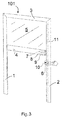
- FIG. 3 and 4 another of a screening device 101 is shown in a perspective view and a side view, respectively.
- the electric drive of the screening device 101 is arranged in the bottom element 4.
- the sensor arrangement includes two sensor elements; a free end component 8 and a position indicator component 10.
- the free end component includes a magmatic element 8, such as a plate of magnetic material and the position indicator component is a permanent magnet 10.
- the sensor elements 7, 9 are Reed or Hall sensors. Since the sensor elements 7 and 9 are spaced longitudinally, the difference in signal between the two sensor elements 7 and 9 indicates the direction of the difference in longitudinal position between the free and 4 and the position indicator 6. Assuming that the window and the covering device are arranged vertically, a stronger signal from the higher placed sensor 7 than from the lower placed sensor 9 is an indication that the position indicator 6 has a longitudinal position that is higher than the free end 4 and thus the free end 4 should move upwards in order to reduce the difference in longitudinal position between the free end 4 and the position indicator 6.
- a stronger signal from the lower placed sensor 9 than from the higher placed sensor 7 is an indication that the position indicator 6 has a longitudinal position that is lower than the free end 4 and thus the free end 4 should move downwards in order to reduce the difference in longitudinal position between the free end 4 and the position indicator 6.
- the permanent magnet 10 When the magnetic element 8 and the permanent magnet 10 are sufficiently close to each other, which will be the case the position indicator 6 and the bottom element 4 are substantially in the same longitudinal position, the permanent magnet 10 will attract the magnetic element 8 such as to form a magnetic connection.
- the metallic element 8 and the permanent magnet 10 are adapted to interact, and particularly to take up a position in alignment with each other, when the bottom element 4 and the position indicator 6 are located in substantially the same longitudinal position. The result is that in any further movement of the bottom element 4 the position indicator 6 will follow the bottom element 4 due to the magnetic force between the metallic element 8 and the permanent magnet 10. So when the screening device is operated by e.g. a remote control, or an automated system operating on timing opening or sensor the position indicator 6 will follow the bottom element 4 and remain aligned.
- the magnetic connection between the bottom element 4 and the position indicator 6 will cause the position indicator to follow the longitudinal position of the bottom element as a slave.
- the user may also manually control the position of the screen 5 and release the position indicator 6 from the bottom element 4 by manually sliding the position indicator and the manual force thereby overcoming the magnetic force and disengaging the magnetic connection.
- a signal is triggered and sent from the sensor element 7, 9 to the electric drive or to a control device of the electric drive means.
- the signal from the sensor elements 7, 9 may cause the electrical drive to reverse its direction of operation to move the bottom element 4 in a direction opposite to the initial direction of movement in case the bottom element 4 has been moved too far, or it may cause the electric drive to stop when the desired positon has been reached, i.e. When the bottom element 4 and the position indicator 6 have substantially the same longitudinal position.
- the at least one sensor element is configured to register the direction of movement that ended the longitudinal alignment of the position indicator 6 and bottom element 4. So the at least one sensor element can register if the position indicator is moved above the bottom element or below the bottom element. This may for example be done by plural sensors or by employing a first signal when the position indicator is moved above the bottom element and a second signal when the position indicator is moved below the bottom element. For example some sensors may be direction sensitive.
- the screening device without the two sensor elements 7, 9 as well as the screen device in which the free end component and/or the position indicator component has been omitted are also feasible. In the latter case the two sensor elements 7, 9 may be used to detect whether the desired position has been reached. In the screening device where both the bottom element component and the position detector component have been omitted by sensing the presence of the position detector 6, and in another embodiment where only the bottom element component has been omitted by sensing the presence of the position detector component.
- the free end component and the position detector component may be used for stopping the movement of the free end 4 by means of the physical interaction or connection between the free end component and the position detector component.
- bottom element positioning device comprises no sensor or detector
- the bottom element positioning device comprises no sensor or detector
- the side rail 2 comprises a magnetic material strip 11 and the position detector 6 is provided with a permanent magnet so that the position detector 6 may be mounted on the side rail 2 by a magnetic attractive force between the magnetic material strip 11 and the permanent magnet.
- a magnetic material insert provided in the side rail 2 may be used.
- a magnetic material strip part or insert may be provided in the position indicator 6 while the side rail 2 is be provided with a permanently magnetic strip.
- the position indicator 6 may be secured to the side rail by means of a snap connection or by means of a guide rail connection, a guide rail being provided on the side rail.
- the position indicator 6 can slide along the side rail 2.
- the side rail provides longitudinal guidance to the position indicator 6.
- the position indicator 6 can be placed substantially anywhere along the length of the side rail 2.
- a third a screening device 102 is shown in a side view.
- the electric drive of the screening device 102 is arranged in the bottom element 4.
- the bottom element positioning device of the screening device 102 comprises a bottom element component and a position indicator component.
- the bottom element component is a switching element, here in the form of three mechanical switches 13a, 13b, 13c, and the position indicator component is a contact element 14 or alternatively a switch.
- a connection is formed between the switches 13a, 13b, 13c and the contact element 14 as the bottom element 4 moves into the position in which it is longitudinally aligned with the position indicator 6.
- connection formed between the switches 13a, 13b, 13c and the contact element 14 causes the electric drive to stop, for instance by simply interrupting the electrical power supply to the electric drive or by forming a suitable electrical connection to the electric drive or to a control device associated with or part of the electric drive.
- a screening device 103 is shown in a side view.
- This screen device is particularly suitable for screening arrangements in which the electric drive is arranged in another part of the screening arrangement 103 than the bottom element 4, for instance as shown inside the tubular shaft in the top element 3.
- the bottom element positioning device of the screening arrangement 103 comprises a sensor element 16 in the form of a position sensor arranged in the position indicator 6.
- the sensor element 16 measures the position of the position indicator 6 and transmits a signal 18 indicative of the position of the position indicator 6 measured to a control device 15 of the electric drive.
- the control device 15 the controls the electric drive and stops the bottom element 4 in response to the signal 18 received, particularly at the position of the position indicator 6 indicated by the signal 18.
- the signal 18 may be transmitted over a wired connection or wirelessly.
- FIG. 5C a fifth embodiment of a screening arrangement 104 according to the invention is shown in a side view.
- This embodiment is particularly suitable for screening arrangements in which the electric drive is arranged in another part of the screening arrangement 104 than the bottom element 4, for instance in the top element 3.
- the bottom element positioning device of the screening device 103 comprises at least one sensor element 17 in the form of a Reed or Hall sensor arranged in the bottom element 4 and a position indicator component in the form of a permanent magnet 10.
- the permanent magnet 10 triggers the sensor element 17 to transmit a signal 18 indicating that a position in which the bottom element 4 and the position indicator 6 are longitudinally aligned has been reached to a control device 15 of the electric drive.
- the control device 15 stops the electric drive and thus the bottom element 4 in response to the signal 18 received.
- the signal 18 may be transmitted over a wired connection or wirelessly.
- any of the screening devices described herein by remote control it is well known to encode a predefined or user-defined preferred screening position, e.g. "screening device 55 % closed", in the remote control.
- a predefined or user-defined preferred screening position e.g. "screening device 55 % closed”
- the controller stores the last manually defined position by means of the position indicator 6 and may stop the screening at this stored position when operated by remote control or a program.
- the magnetic coupling between the position indicator 6 and the bottom element 4 may alternatively be provided by means of a latch or a spring which snaps into a recess.
- the position indicator 6 may be connected to a cord and hereby the position indicator 6 sensors may be placed remote.
- the disclosed screening operation may be combined with further screening limit detection at the top or bottom.
- the position indicator 6 may control the position of multiple screenings so a zone with multiple screenings is linked.
- the electric drive may be provided in the bottom element 4 so the electronics are located in the bottom element and enable a reliable and user friendly operation.
Landscapes
- Engineering & Computer Science (AREA)
- Structural Engineering (AREA)
- Architecture (AREA)
- Civil Engineering (AREA)
- Power-Operated Mechanisms For Wings (AREA)
Claims (18)
- Dispositif d'écran (100, 101, 102, 103, 104) destiné à protéger une fenêtre (1), ledit dispositif d'écran (101) comprenant :un écran (5) d'une longueur modifiable (L), une largeur fixe (W) entre deux bords dudit écran (5) et une extrémité libre positionnable (4), la position longitudinale de ladite extrémité libre (4) déterminant la longueur (L) dudit écran (5),une commande électrique fonctionnellement reliée audit écran (5) pour le réglage de la position longitudinale de ladite extrémité libre (4),un élément de guidage allongé, parallèle auxdits deux bords et disposé à côté de l'un desdits deux bords,un indicateur de position (6) permettant d'indiquer manuellement une position longitudinale souhaitée de ladite extrémité libre, la position longitudinale dudit indicateur de position (6) pouvant être réglée librement manuellement le long dudit élément de guidage allongé,un système de détection configuré pour détecter une différence entre la position longitudinale réelle de ladite extrémité libre (4) et la position longitudinale réelle dudit indicateur de position (6),un circuit ou processeur relié audit système de détection,ledit circuit ou processeur étant configuré pour activer ladite commande électrique afin de déplacer ladite extrémité libre (4) dans une direction réduisant la différence détectée entre la position longitudinale réelle de ladite extrémité libre (4) et la position longitudinale dudit indicateur de position (6).
- Dispositif d'écran (101) selon la revendication 1, dans lequel ledit circuit ou processeur est configuré pour contrôler la position longitudinale de ladite extrémité libre (4) en fonction de la position longitudinale dudit indicateur de position (6).
- Dispositif d'écran (101) selon la revendication 1 ou 2, dans lequel ledit système de détection est configuré pour détecter la direction de la différence détectée dans la position longitudinale entre la position longitudinale réelle de ladite extrémité libre (4) et la position longitudinale réelle dudit indicateur de position (6).
- Dispositif d'écran (101) selon l'une quelconque des revendications 1 à 3, dans lequel ledit système de détection et ledit circuit ou processeur sont agencés de manière à former une boucle fermée pour commander la position longitudinale de ladite extrémité libre (4) dans le but de réduire la différence détectée dans la position longitudinale entre la position longitudinale réelle de ladite extrémité libre (4) et la position longitudinale réelle dudit indicateur de position (6).
- Dispositif d'écran (101) selon l'une quelconque des revendications 1 à 4, dans lequel ledit indicateur de position (6) est disposé sur ledit élément de guidage allongé.
- Dispositif d'écran (101) selon l'une quelconque des revendications 1 à 5, dans lequel ledit indicateur de position (6) peut être positionné de façon coulissante le long dudit élément de guidage allongé.
- Dispositif d'écran (101) selon l'une quelconque des revendications 1 à 6, comprenant en outre deux rails espacés parallèles (1, 2) destinés à guider lesdits deux bords dudit écran (5).
- Dispositif d'écran (101) selon la revendication 7, dans lequel ledit élément de guidage allongé est formé par l'un desdits rails espacés parallèles (1, 2).
- Dispositif d'écran (101) selon l'une quelconque des revendications 1 à 8, dans lequel ledit système de détection comprend un composant de détection à ladite extrémité libre (4) et/ou un composant de détection sur ledit indicateur de position (6).
- Dispositif d'écran (101) selon l'une quelconque des revendications 1 à 9, dans lequel ledit indicateur de position (6) comprend un aimant ou un composant magnétique.
- Dispositif d'écran (101) selon l'invention l'une quelconque des revendications 1 à 10, dans lequel l'au moins un élément de détection (7, 9) est l'un quelconque parmi : un capteur de position, un capteur inductif, un capteur Reed et un capteur Hall.
- Dispositif d'écran (101) selon l'une quelconque des revendications 1 à 11, dans lequel l'indicateur de position (6) est agencé de façon détachable sur l'un des deux rails latéraux (1, 2).
- Dispositif d'écran (101) selon l'une quelconque des revendications 1 à 12, dans lequel ledit indicateur de position (6) est accouplé de façon amovible à ladite extrémité libre (4), de telle façon que ledit indicateur de position (6) se déplace conjointement avec ledit bord libre (4) lorsque ladite extrémité libre (4) se déplace longitudinalement.
- Dispositif d'écran (101) selon la revendication 13, dans lequel ledit indicateur de position (6) est accouplé magnétiquement à ladite extrémité libre (4) ou accouplé mécaniquement à ladite extrémité libre (4), avec un certain degré de flexibilité permettant un déplacement mineur dans la direction longitudinale.
- Procédé destiné à commander la position d'une extrémité libre (4) d'un écran d'un dispositif d'écran (101) destiné à protéger une fenêtre, ledit écran (5) présentant une longueur modifiable (L), une largeur fixe (W) entre deux bords dudit écran (5) et une extrémité libre positionnable (4), la position longitudinale de ladite extrémité libre (4) déterminant la longueur (L) dudit écran, et une commande électrique fonctionnellement reliée audit écran pour régler la position de ladite extrémité libre,
ledit procédé comprenant :la détection de la différence entre la position longitudinale réelle d'un indicateur de position positionnable manuellement et la position longitudinale réelle de ladite extrémité libre (4), etl'activation de ladite commande électrique pour déplacer ladite extrémité libre (4) dans une direction réduisant ladite différence détectée dans la position longitudinale. - Procédé selon la revendication 15, comprenant en outre la désactivation de ladite commande électrique lorsque ladite différence détectée est nulle ou inférieure à un seuil prédéterminé.
- Procédé selon la revendication 15 ou 16, comprenant en outre le positionnement manuel dudit indicateur de position (6) afin d'indiquer une position longitudinale souhaitée de ladite extrémité libre (4).
- Procédé selon l'invention l'une quelconque des revendications 15 à 17, comprenant en outre le réglage de la position de ladite extrémité libre (4) par activation dudit moyen de commande électrique à l'aide d'une autre forme d'interface d'utilisateur que ledit indicateur de position (6).
Priority Applications (1)
| Application Number | Priority Date | Filing Date | Title |
|---|---|---|---|
| EP14196204.3A EP2886784B1 (fr) | 2013-12-17 | 2014-12-04 | Dispositif de blindage pour fenêtre et procédé associé |
Applications Claiming Priority (2)
| Application Number | Priority Date | Filing Date | Title |
|---|---|---|---|
| EP13197805.8A EP2886783A1 (fr) | 2013-12-17 | 2013-12-17 | Dispositif de criblage pour fenêtre |
| EP14196204.3A EP2886784B1 (fr) | 2013-12-17 | 2014-12-04 | Dispositif de blindage pour fenêtre et procédé associé |
Publications (2)
| Publication Number | Publication Date |
|---|---|
| EP2886784A1 EP2886784A1 (fr) | 2015-06-24 |
| EP2886784B1 true EP2886784B1 (fr) | 2016-10-19 |
Family
ID=49880427
Family Applications (2)
| Application Number | Title | Priority Date | Filing Date |
|---|---|---|---|
| EP13197805.8A Withdrawn EP2886783A1 (fr) | 2013-12-17 | 2013-12-17 | Dispositif de criblage pour fenêtre |
| EP14196204.3A Active EP2886784B1 (fr) | 2013-12-17 | 2014-12-04 | Dispositif de blindage pour fenêtre et procédé associé |
Family Applications Before (1)
| Application Number | Title | Priority Date | Filing Date |
|---|---|---|---|
| EP13197805.8A Withdrawn EP2886783A1 (fr) | 2013-12-17 | 2013-12-17 | Dispositif de criblage pour fenêtre |
Country Status (1)
| Country | Link |
|---|---|
| EP (2) | EP2886783A1 (fr) |
Families Citing this family (4)
| Publication number | Priority date | Publication date | Assignee | Title |
|---|---|---|---|---|
| US10240391B2 (en) * | 2015-09-24 | 2019-03-26 | Comfortex Window Fashions | Switching apparatus and system for window shadings with powered adjustment |
| EP4390044A3 (fr) * | 2022-12-19 | 2024-07-24 | VKR Holding A/S | Dispositif d'occultation comprenant un indicateur de position et procédé de fonctionnement du dispositif d'occultation |
| EP4390045A3 (fr) * | 2022-12-19 | 2024-07-24 | VKR Holding A/S | Dispositif d'occultation comprenant un indicateur de position avec des moyens de mise en prise par encliquetage |
| EP4390046B1 (fr) * | 2022-12-19 | 2025-12-24 | VKR Holding A/S | Procédé de fonctionnement d'un dispositif d'occultation, unité de commande et dispositif d'occultation |
Family Cites Families (5)
| Publication number | Priority date | Publication date | Assignee | Title |
|---|---|---|---|---|
| DE9319657U1 (de) * | 1993-12-21 | 1994-02-17 | Hüppe Form Sonnenschutz- und Raumtrennsysteme GmbH, 26133 Oldenburg | Schalteinrichtung zum Schalten des Elektroantriebs von Sicht- oder Sonnen-Schutzvorrichtungen |
| DE19605273C2 (de) * | 1996-02-13 | 2000-08-31 | Horst H Goldner | Rollo mit einem auf eine Wickelwelle auf- und von dieser abwickelbaren Wickelmedium |
| IT1287994B1 (it) | 1996-11-27 | 1998-09-10 | Finvetro Srl | Dispositivo di controllo e comando della corsa di mezzi di intercettazione dei raggi luminosi in vetrocamere |
| DE102006015507A1 (de) * | 2006-03-31 | 2007-10-04 | Hlw Gmbh | Rollladensystem |
| WO2010076820A1 (fr) * | 2008-12-30 | 2010-07-08 | Pellini S.P.A. | Kit motorisé pour volet |
-
2013
- 2013-12-17 EP EP13197805.8A patent/EP2886783A1/fr not_active Withdrawn
-
2014
- 2014-12-04 EP EP14196204.3A patent/EP2886784B1/fr active Active
Also Published As
| Publication number | Publication date |
|---|---|
| EP2886783A1 (fr) | 2015-06-24 |
| EP2886784A1 (fr) | 2015-06-24 |
Similar Documents
| Publication | Publication Date | Title |
|---|---|---|
| CN108463605B (zh) | 用于具有连续绳环的窗户覆盖系统的外置电动机驱动系统 | |
| EP2886784B1 (fr) | Dispositif de blindage pour fenêtre et procédé associé | |
| EP2167776B1 (fr) | Arbre d'enroulement avec un moteur tubulaire et un détecteur de mouvement électronique | |
| US10352097B2 (en) | Touch hem bar control | |
| EP2683905B1 (fr) | Habillage de fenêtre motorisé alimenté par piles présentant une position d'entretien | |
| US10550637B2 (en) | Obstruction detection system for motorized window shades and method of use | |
| KR200494075Y1 (ko) | 통전 조절부를 갖는 스위칭 장치 및 창문 가리개 시스템 | |
| EP3091168B1 (fr) | Dispositif de criblage pour une fenêtre, procédé pour faire fonctionner un dispositif de criblage et utilisation d'un dispositif de criblage | |
| JP2011111763A (ja) | 電動日射遮蔽装置及び電動日射遮蔽装置の制御方法 | |
| JP6076837B2 (ja) | 建築用電動シャッター装置 | |
| WO2018065186A1 (fr) | Dispositif de commande de rideau | |
| KR101397187B1 (ko) | 창문 자동 닫힘장치 | |
| US10227821B2 (en) | Electrically and manually adjustable screening device and method for screening a window | |
| US9328556B2 (en) | Motorized transitional shade system | |
| CN118369486A (zh) | 电动窗帘 | |
| WO2016064262A1 (fr) | Dispositif et procédé pour la commande duale de mécanismes de persiennes ou de rideaux | |
| KR102160421B1 (ko) | 복층유리용 자동블라인드장치 | |
| CN205778423U (zh) | 一种用于窗帘开合系统的带手拉起动的控制器 | |
| EP0845572A1 (fr) | Dispositif pour contrôler et pour mouvoir un moyen d'obturation de la lumière dans une unité de double vitrage | |
| AU2014100040A4 (en) | A motorised window covering | |
| EP4644658A1 (fr) | Procédé de fonctionnement d'un ensemble de volet roulant à lames orientables | |
| JP6173723B2 (ja) | 動作回数表示装置及び開閉装置 | |
| KR20100057154A (ko) | 창문개폐장치 | |
| TWM680362U (zh) | 用於捲簾的限位裝置 | |
| KR20130050029A (ko) | 전동 롤 스크린 |
Legal Events
| Date | Code | Title | Description |
|---|---|---|---|
| PUAI | Public reference made under article 153(3) epc to a published international application that has entered the european phase |
Free format text: ORIGINAL CODE: 0009012 |
|
| 17P | Request for examination filed |
Effective date: 20141204 |
|
| AK | Designated contracting states |
Kind code of ref document: A1 Designated state(s): AL AT BE BG CH CY CZ DE DK EE ES FI FR GB GR HR HU IE IS IT LI LT LU LV MC MK MT NL NO PL PT RO RS SE SI SK SM TR |
|
| AX | Request for extension of the european patent |
Extension state: BA ME |
|
| R17P | Request for examination filed (corrected) |
Effective date: 20150630 |
|
| RBV | Designated contracting states (corrected) |
Designated state(s): AL AT BE BG CH CY CZ DE DK EE ES FI FR GB GR HR HU IE IS IT LI LT LU LV MC MK MT NL NO PL PT RO RS SE SI SK SM TR |
|
| REG | Reference to a national code |
Ref country code: DE Ref legal event code: R079 Ref document number: 602014004346 Country of ref document: DE Free format text: PREVIOUS MAIN CLASS: E06B0009880000 Ipc: E06B0009680000 |
|
| GRAP | Despatch of communication of intention to grant a patent |
Free format text: ORIGINAL CODE: EPIDOSNIGR1 |
|
| RIC1 | Information provided on ipc code assigned before grant |
Ipc: E06B 9/68 20060101AFI20160502BHEP Ipc: E06B 9/90 20060101ALI20160502BHEP Ipc: E06B 9/88 20060101ALI20160502BHEP |
|
| INTG | Intention to grant announced |
Effective date: 20160601 |
|
| GRAS | Grant fee paid |
Free format text: ORIGINAL CODE: EPIDOSNIGR3 |
|
| GRAA | (expected) grant |
Free format text: ORIGINAL CODE: 0009210 |
|
| AK | Designated contracting states |
Kind code of ref document: B1 Designated state(s): AL AT BE BG CH CY CZ DE DK EE ES FI FR GB GR HR HU IE IS IT LI LT LU LV MC MK MT NL NO PL PT RO RS SE SI SK SM TR |
|
| REG | Reference to a national code |
Ref country code: GB Ref legal event code: FG4D |
|
| REG | Reference to a national code |
Ref country code: CH Ref legal event code: EP |
|
| REG | Reference to a national code |
Ref country code: AT Ref legal event code: REF Ref document number: 838516 Country of ref document: AT Kind code of ref document: T Effective date: 20161115 |
|
| REG | Reference to a national code |
Ref country code: IE Ref legal event code: FG4D |
|
| REG | Reference to a national code |
Ref country code: FR Ref legal event code: PLFP Year of fee payment: 3 |
|
| REG | Reference to a national code |
Ref country code: DE Ref legal event code: R096 Ref document number: 602014004346 Country of ref document: DE |
|
| REG | Reference to a national code |
Ref country code: NL Ref legal event code: MP Effective date: 20161019 |
|
| REG | Reference to a national code |
Ref country code: LT Ref legal event code: MG4D |
|
| PG25 | Lapsed in a contracting state [announced via postgrant information from national office to epo] |
Ref country code: LV Free format text: LAPSE BECAUSE OF FAILURE TO SUBMIT A TRANSLATION OF THE DESCRIPTION OR TO PAY THE FEE WITHIN THE PRESCRIBED TIME-LIMIT Effective date: 20161019 |
|
| REG | Reference to a national code |
Ref country code: AT Ref legal event code: MK05 Ref document number: 838516 Country of ref document: AT Kind code of ref document: T Effective date: 20161019 |
|
| PG25 | Lapsed in a contracting state [announced via postgrant information from national office to epo] |
Ref country code: SE Free format text: LAPSE BECAUSE OF FAILURE TO SUBMIT A TRANSLATION OF THE DESCRIPTION OR TO PAY THE FEE WITHIN THE PRESCRIBED TIME-LIMIT Effective date: 20161019 Ref country code: LT Free format text: LAPSE BECAUSE OF FAILURE TO SUBMIT A TRANSLATION OF THE DESCRIPTION OR TO PAY THE FEE WITHIN THE PRESCRIBED TIME-LIMIT Effective date: 20161019 Ref country code: GR Free format text: LAPSE BECAUSE OF FAILURE TO SUBMIT A TRANSLATION OF THE DESCRIPTION OR TO PAY THE FEE WITHIN THE PRESCRIBED TIME-LIMIT Effective date: 20170120 Ref country code: NO Free format text: LAPSE BECAUSE OF FAILURE TO SUBMIT A TRANSLATION OF THE DESCRIPTION OR TO PAY THE FEE WITHIN THE PRESCRIBED TIME-LIMIT Effective date: 20170119 |
|
| PG25 | Lapsed in a contracting state [announced via postgrant information from national office to epo] |
Ref country code: RS Free format text: LAPSE BECAUSE OF FAILURE TO SUBMIT A TRANSLATION OF THE DESCRIPTION OR TO PAY THE FEE WITHIN THE PRESCRIBED TIME-LIMIT Effective date: 20161019 Ref country code: AT Free format text: LAPSE BECAUSE OF FAILURE TO SUBMIT A TRANSLATION OF THE DESCRIPTION OR TO PAY THE FEE WITHIN THE PRESCRIBED TIME-LIMIT Effective date: 20161019 Ref country code: BE Free format text: LAPSE BECAUSE OF FAILURE TO SUBMIT A TRANSLATION OF THE DESCRIPTION OR TO PAY THE FEE WITHIN THE PRESCRIBED TIME-LIMIT Effective date: 20161019 Ref country code: HR Free format text: LAPSE BECAUSE OF FAILURE TO SUBMIT A TRANSLATION OF THE DESCRIPTION OR TO PAY THE FEE WITHIN THE PRESCRIBED TIME-LIMIT Effective date: 20161019 Ref country code: ES Free format text: LAPSE BECAUSE OF FAILURE TO SUBMIT A TRANSLATION OF THE DESCRIPTION OR TO PAY THE FEE WITHIN THE PRESCRIBED TIME-LIMIT Effective date: 20161019 Ref country code: PT Free format text: LAPSE BECAUSE OF FAILURE TO SUBMIT A TRANSLATION OF THE DESCRIPTION OR TO PAY THE FEE WITHIN THE PRESCRIBED TIME-LIMIT Effective date: 20170220 Ref country code: IS Free format text: LAPSE BECAUSE OF FAILURE TO SUBMIT A TRANSLATION OF THE DESCRIPTION OR TO PAY THE FEE WITHIN THE PRESCRIBED TIME-LIMIT Effective date: 20170219 Ref country code: FI Free format text: LAPSE BECAUSE OF FAILURE TO SUBMIT A TRANSLATION OF THE DESCRIPTION OR TO PAY THE FEE WITHIN THE PRESCRIBED TIME-LIMIT Effective date: 20161019 Ref country code: NL Free format text: LAPSE BECAUSE OF FAILURE TO SUBMIT A TRANSLATION OF THE DESCRIPTION OR TO PAY THE FEE WITHIN THE PRESCRIBED TIME-LIMIT Effective date: 20161019 Ref country code: PL Free format text: LAPSE BECAUSE OF FAILURE TO SUBMIT A TRANSLATION OF THE DESCRIPTION OR TO PAY THE FEE WITHIN THE PRESCRIBED TIME-LIMIT Effective date: 20161019 |
|
| REG | Reference to a national code |
Ref country code: DE Ref legal event code: R097 Ref document number: 602014004346 Country of ref document: DE |
|
| PG25 | Lapsed in a contracting state [announced via postgrant information from national office to epo] |
Ref country code: SK Free format text: LAPSE BECAUSE OF FAILURE TO SUBMIT A TRANSLATION OF THE DESCRIPTION OR TO PAY THE FEE WITHIN THE PRESCRIBED TIME-LIMIT Effective date: 20161019 Ref country code: RO Free format text: LAPSE BECAUSE OF FAILURE TO SUBMIT A TRANSLATION OF THE DESCRIPTION OR TO PAY THE FEE WITHIN THE PRESCRIBED TIME-LIMIT Effective date: 20161019 Ref country code: CZ Free format text: LAPSE BECAUSE OF FAILURE TO SUBMIT A TRANSLATION OF THE DESCRIPTION OR TO PAY THE FEE WITHIN THE PRESCRIBED TIME-LIMIT Effective date: 20161019 Ref country code: EE Free format text: LAPSE BECAUSE OF FAILURE TO SUBMIT A TRANSLATION OF THE DESCRIPTION OR TO PAY THE FEE WITHIN THE PRESCRIBED TIME-LIMIT Effective date: 20161019 Ref country code: DK Free format text: LAPSE BECAUSE OF FAILURE TO SUBMIT A TRANSLATION OF THE DESCRIPTION OR TO PAY THE FEE WITHIN THE PRESCRIBED TIME-LIMIT Effective date: 20161019 |
|
| PLBE | No opposition filed within time limit |
Free format text: ORIGINAL CODE: 0009261 |
|
| STAA | Information on the status of an ep patent application or granted ep patent |
Free format text: STATUS: NO OPPOSITION FILED WITHIN TIME LIMIT |
|
| PG25 | Lapsed in a contracting state [announced via postgrant information from national office to epo] |
Ref country code: IT Free format text: LAPSE BECAUSE OF FAILURE TO SUBMIT A TRANSLATION OF THE DESCRIPTION OR TO PAY THE FEE WITHIN THE PRESCRIBED TIME-LIMIT Effective date: 20161019 Ref country code: SM Free format text: LAPSE BECAUSE OF FAILURE TO SUBMIT A TRANSLATION OF THE DESCRIPTION OR TO PAY THE FEE WITHIN THE PRESCRIBED TIME-LIMIT Effective date: 20161019 Ref country code: BG Free format text: LAPSE BECAUSE OF FAILURE TO SUBMIT A TRANSLATION OF THE DESCRIPTION OR TO PAY THE FEE WITHIN THE PRESCRIBED TIME-LIMIT Effective date: 20170119 |
|
| 26N | No opposition filed |
Effective date: 20170720 |
|
| PG25 | Lapsed in a contracting state [announced via postgrant information from national office to epo] |
Ref country code: MC Free format text: LAPSE BECAUSE OF FAILURE TO SUBMIT A TRANSLATION OF THE DESCRIPTION OR TO PAY THE FEE WITHIN THE PRESCRIBED TIME-LIMIT Effective date: 20161019 |
|
| REG | Reference to a national code |
Ref country code: IE Ref legal event code: MM4A |
|
| PG25 | Lapsed in a contracting state [announced via postgrant information from national office to epo] |
Ref country code: LU Free format text: LAPSE BECAUSE OF NON-PAYMENT OF DUE FEES Effective date: 20161204 |
|
| REG | Reference to a national code |
Ref country code: FR Ref legal event code: PLFP Year of fee payment: 4 |
|
| PG25 | Lapsed in a contracting state [announced via postgrant information from national office to epo] |
Ref country code: IE Free format text: LAPSE BECAUSE OF NON-PAYMENT OF DUE FEES Effective date: 20161204 Ref country code: SI Free format text: LAPSE BECAUSE OF FAILURE TO SUBMIT A TRANSLATION OF THE DESCRIPTION OR TO PAY THE FEE WITHIN THE PRESCRIBED TIME-LIMIT Effective date: 20161019 |
|
| PG25 | Lapsed in a contracting state [announced via postgrant information from national office to epo] |
Ref country code: HU Free format text: LAPSE BECAUSE OF FAILURE TO SUBMIT A TRANSLATION OF THE DESCRIPTION OR TO PAY THE FEE WITHIN THE PRESCRIBED TIME-LIMIT; INVALID AB INITIO Effective date: 20141204 |
|
| PG25 | Lapsed in a contracting state [announced via postgrant information from national office to epo] |
Ref country code: MK Free format text: LAPSE BECAUSE OF FAILURE TO SUBMIT A TRANSLATION OF THE DESCRIPTION OR TO PAY THE FEE WITHIN THE PRESCRIBED TIME-LIMIT Effective date: 20161019 Ref country code: CY Free format text: LAPSE BECAUSE OF FAILURE TO SUBMIT A TRANSLATION OF THE DESCRIPTION OR TO PAY THE FEE WITHIN THE PRESCRIBED TIME-LIMIT Effective date: 20161019 |
|
| REG | Reference to a national code |
Ref country code: CH Ref legal event code: PL |
|
| PG25 | Lapsed in a contracting state [announced via postgrant information from national office to epo] |
Ref country code: MT Free format text: LAPSE BECAUSE OF NON-PAYMENT OF DUE FEES Effective date: 20161204 |
|
| PG25 | Lapsed in a contracting state [announced via postgrant information from national office to epo] |
Ref country code: TR Free format text: LAPSE BECAUSE OF FAILURE TO SUBMIT A TRANSLATION OF THE DESCRIPTION OR TO PAY THE FEE WITHIN THE PRESCRIBED TIME-LIMIT Effective date: 20161019 |
|
| PG25 | Lapsed in a contracting state [announced via postgrant information from national office to epo] |
Ref country code: CH Free format text: LAPSE BECAUSE OF NON-PAYMENT OF DUE FEES Effective date: 20171231 Ref country code: LI Free format text: LAPSE BECAUSE OF NON-PAYMENT OF DUE FEES Effective date: 20171231 |
|
| PG25 | Lapsed in a contracting state [announced via postgrant information from national office to epo] |
Ref country code: AL Free format text: LAPSE BECAUSE OF FAILURE TO SUBMIT A TRANSLATION OF THE DESCRIPTION OR TO PAY THE FEE WITHIN THE PRESCRIBED TIME-LIMIT Effective date: 20161019 |
|
| PGFP | Annual fee paid to national office [announced via postgrant information from national office to epo] |
Ref country code: DE Payment date: 20251104 Year of fee payment: 12 |
|
| PGFP | Annual fee paid to national office [announced via postgrant information from national office to epo] |
Ref country code: GB Payment date: 20251114 Year of fee payment: 12 |
|
| PGFP | Annual fee paid to national office [announced via postgrant information from national office to epo] |
Ref country code: FR Payment date: 20251124 Year of fee payment: 12 |