EP2902155B1 - Dispositif de raccordement pour un dispositif d'évacuation de poussière et machine-outil portative - Google Patents
Dispositif de raccordement pour un dispositif d'évacuation de poussière et machine-outil portative Download PDFInfo
- Publication number
- EP2902155B1 EP2902155B1 EP15150408.1A EP15150408A EP2902155B1 EP 2902155 B1 EP2902155 B1 EP 2902155B1 EP 15150408 A EP15150408 A EP 15150408A EP 2902155 B1 EP2902155 B1 EP 2902155B1
- Authority
- EP
- European Patent Office
- Prior art keywords
- inlet
- outlet
- latching
- contours
- connecting device
- Prior art date
- Legal status (The legal status is an assumption and is not a legal conclusion. Google has not performed a legal analysis and makes no representation as to the accuracy of the status listed.)
- Active
Links
Images

Classifications
-
- B—PERFORMING OPERATIONS; TRANSPORTING
- B25—HAND TOOLS; PORTABLE POWER-DRIVEN TOOLS; MANIPULATORS
- B25F—COMBINATION OR MULTI-PURPOSE TOOLS NOT OTHERWISE PROVIDED FOR; DETAILS OR COMPONENTS OF PORTABLE POWER-DRIVEN TOOLS NOT PARTICULARLY RELATED TO THE OPERATIONS PERFORMED AND NOT OTHERWISE PROVIDED FOR
- B25F5/00—Details or components of portable power-driven tools not particularly related to the operations performed and not otherwise provided for
Definitions
- the invention relates to a connection device for connecting a dust removal device, in particular a suction hose or a dust collection container, to a hand-held machine tool or a vacuum cleaner, according to the preamble of claim 1.
- connection devices in which a dust removal device, for example a suction hose or a dust collecting container, are rotatable relative to the hand-held machine tool or the vacuum cleaner.
- a dust removal device for example a suction hose or a dust collecting container
- an inlet member, an outlet member, and a connecting member-forming portion formed therebetween are integral, but are rotatable, for example, to a spigot or the like of the hand-held power tool or the vacuum cleaner.
- the suction hose can rotate relative to the hand-held machine tool on the basis of the connecting device. Not in all cases this is desirable.
- the unfavorably twisted suction hose comes into contact with the workpiece to be machined, so there along it drags and leads to damage.
- a dust collecting container must be firmly clamped or locked in accordance with a fitting of the hand-held machine tool so that it does not rotate relative to the hand-held machine tool or moved in any other way and as explained, for example gets in contact with the workpiece in an undesirable manner.
- connection device for connecting a dust removal device to a hand-held machine tool
- connection device according to the technical teaching of claim 1 is provided.
- outlet element and the inlet element can be fixed relative to one another in a form-fitting manner, so that the angle of rotation between the two components is maintained.
- a dust removal device in the context of the invention is to be understood that it is suitable for the removal of dust away from the hand machine tool, so for example for collecting dust or particles, but also for guiding the dust or particles, for example, to the vacuum cleaner.
- the connecting device according to the invention forms at least in parts, namely with respect to, for example, the inlet element or the outlet element, preferably a component of the dust removal device, for example, a component of a suction hose or the dust collection container.
- the inlet element can therefore be arranged, for example, on the suction hose or dust collecting container, while the outlet element is arranged, for example, on the hand-held machine tool, for example on its dust removal channel.
- a system is also provided which comprises, for example, a suction hose, the connecting device and the hand-held machine tool or the hand-held machine tool and the dust collecting container, which are connected to one another by the connecting device according to the invention.
- a suction hose to a vacuum cleaner on the basis of the connecting device according to the invention.
- the inlet element is arranged fixedly or permanently mounted on a dust outlet or suction connection of the hand-held machine tool, in particular rotationally fixed.
- the inlet member may also form an integral part of the dust outlet or suction port.
- the inlet member may form a fixed or integral part of a vacuum cleaner or a suction hose or a dust collection container or at least be arranged there, in particular rotatably arranged.
- the inlet element may be connected in a rotationally fixed manner to the suction connection on the basis of positive-locking contours and / or to be glued or welded to the suction connection or the like. But so can also the outlet with the suction hose or the vacuum cleaner or the dust collector be connected.
- the inlet element may for example be inserted into the suction connection or plugged onto the suction connection.
- a system according to the invention may, for example, also comprise two connection devices according to the invention, one of which is arranged between the suction hose and the vacuum cleaner and another between the suction hose and the hand-held machine tool.
- inlet member or “outlet member” are not intended to be limiting.
- an inlet element in the following description is generally the inlet-side element of the connection device in the flow direction of the suction flow or of the particle or dust, while the air flow or suction flow leaves the connection device again via the outlet element.
- the connecting element may be integral with the inlet element or the outlet element.
- the inlet element or the outlet element at the same time form or comprise the connecting element.
- the connecting element is rotatably mounted on one of the elements of the inlet element or outlet element.
- the pivot bearing is provided on the connecting element, ie that the connecting element has a first portion which is integrally or firmly connected to the inlet element or is detachably connectable, and has a second portion which integrally or fixedly connected to the outlet member is or or is detachably connectable.
- the outlet element and the inlet element can also be non-detachably but rotatably connected to one another. In a particularly preferred embodiment of the invention, they can also be components which can be detached from one another. It is preferred if the connecting element comprises connecting means for releasably connecting the outlet element with the inlet element or forms such a connecting means.
- the connecting means may comprise, for example, locking means, plug-in means, screw means or the like. A jamming of the connecting element with, for example, the inlet element or outlet element is readily possible.
- the positive locking contours are preferably arranged on the outlet element and the inlet element and are engaged with one another on the connecting element when the connecting element connects the outlet element and the inlet element. Consequently, therefore, the connecting element is not directly involved in the fixing of the outlet element in the correct angle of rotation and with the inlet element, ie in the function as at least temporary rotation lock, but serves as a coupling element.
- the form-fitting contours comprise latching contours which engage in one another or latch together relative to one another in at least two rotational angle positions of the inlet element and the outlet element.
- the outlet element and the inlet element by the connecting element to each other are held, however, are rotatable relative to each other and thereby lock in different, at least two, rotational positions relative to each other.
- the latching contours are expediently arranged on the outlet element and on the inlet element.
- the latching contours it is also possible for the latching contours to be provided, for example, between the inlet element and the connecting element or between the connecting element and the outlet element.
- locking contours are provided between the connecting element and the inlet element and additionally between the outlet element and the connecting element.
- the latching contours expediently comprise a latching projection arranged on a resilient spring arm or otherwise spring-loaded or resilient, which is arranged on one element, thus for example the outlet element or inlet element, and engages in detent recesses on the other element of outlet element or inlet element.
- a plurality of resilient latching projections such as spring arms with latching projection, may be provided. In this case, it may also be sufficient that only a single latching recess is provided, which then with the respective latching projection or the respective latching projections in the at least two rotational angular positions of the Inlet element and the outlet element locked relative to each other.
- Preference is given to an arrangement of a plurality of, for example, tooth-like juxtaposed, recessed recesses.
- latching depressions and the resilient latching projection are configured for an axial latching operation parallel to the longitudinal axis or along the longitudinal axis of the outlet element or of the inlet element.
- an axis parallel or aligned with a longitudinal axis or longitudinal axis of the respective tubular outlet member or inlet member is the actuating axis along which the locking projection can engage or disengage from the detent recess.
- the outlet element, the inlet element or the connecting element or even several thereof may have a curved section.
- a suction hose for example, laterally from the Hand machine tool be taken away.
- a dust collecting container can be rotated into a favorable position relative to the housing of the hand-held machine tool and, as provided according to the invention, is fixed in the correct angle of rotation on the hand-held machine tool by the connecting device.
- the connecting element is expediently lockable on at least one of the elements comprising the outlet element or the inlet element or both by means of screw contours or locking contours can be latched.
- the connecting element for example a nut, can be screwed to the inlet element or the outlet element.
- the connecting element for example the aforementioned nut, is expediently rotatably mounted on one of the elements comprising the outlet element or the inlet element by means of a rotary bearing.
- the connecting element it is possible for the connecting element to be mounted rotatably on both elements, namely on the outlet element and on the inlet element.
- the inlet member Preferably, for rotatably supporting the inlet member with respect to the outlet member or the pivot bearing between the connecting element and the inlet member or the outlet member is provided.
- the rotatable mounting of the connecting element on the inlet element or outlet element at the same time forms the or a pivot bearing between inlet element and outlet element.
- the nut or the connecting element designed in another way is rotatably mounted only on one of the elements comprising the outlet element or the inlet element, while for coupling to the other element (ie the inlet element or the outlet element), the aforementioned screw contours or Rastkonturen serve.
- the connecting element on one of the elements comprising the outlet element or the inlet element can be secured against rotation by means of anti-rotation means.
- the connecting element is rotatably mounted on the outlet element, for example, but can be secured against rotation on the other element, namely the inlet element, by means of anti-rotation means.
- the outlet element is then rotatable relative to the inlet element, but not the connecting element.
- the connecting element for example, to the outlet or the inlet element so to speak infectable.
- the pivot bearing comprises bearing elements designed as latching elements, which engage with each other during plug-in mounting and form the pivot bearing.
- the connecting element is so to speak only infected to the outlet or inlet element, wherein the locking elements or bearing components automatically engage, for example, lock together, and thereby form the pivot bearing.
- the connecting element is determined for example by means of a flange or the like on the inlet element or outlet element in order to produce the rotary bearing in this way.
- the connecting element and the respective element comprising the outlet element or the inlet element expediently engage each other with tubular bearing sections.
- the rotary bearing comprises, for example, at least one rotary bearing projection, which extends in the circumferential direction and projects radially inward or radially outwards and which extends into a likewise circumferentially extending rotary bearing recess on the other body, namely the connecting element, the outlet element or inlet element intervenes. So grab it the annular DrehlagerausEnglishung and the likewise annular rotary bearing projection in the sense of a latching into one another. It is preferred if the rotary bearing projection and / or the rotary bearing recess are segmented, which allows, for example, an expansion or compression of the respective body on which the rotary bearing projection or the rotary bearing recess is arranged.
- the screw connection of the connecting element with the inlet element or the outlet element expediently provides bayonet contours, i. the screw contours comprise bayonet contours or are formed by bayonet contours.
- the screw contours comprise bayonet contours or are formed by bayonet contours.
- circumferential screw contours can also be provided, that is to say that the connecting element is screwed to the inlet element or the outlet element by a screw movement comprising several revolutions.
- the bayonet connection is easier to operate, so for example, it only needs one turn of 60-90 °.
- the screw contours are expediently associated with the aforementioned anti-rotation means, for example, the locking means, which engage in a screwing the screw contours together to prevent rotation of the screw engaged. Thus, it can not solve the screw.
- the latching means which hold the screw contours against rotation, so serve as anti-rotation, a higher holding force or latching force than latching contours, which serve as the form-fitting contours for fixing the outlet and the inlet element in predetermined rotational positions relative to each other. In this way, it is ensured that the screw, for example, the bayonet connection, not accidentally dissolves, if the Inlet member and the outlet member are rotated relative to each other.
- the locking means comprise, for example, at least one locking cam.
- the locking cams or other latching means which serve to prevent rotation are expediently arranged next to a screw contour, for example a bayonet contour, transversely to the screwing direction, that is to say in the longitudinal axis direction of the connecting element and of the other element comprising the inlet element or outlet element.
- a locking contour for example the locking cam, in the direction of rotation behind or in front of the screw contour or bayonet contour.
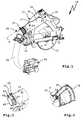
- a handheld power tool 10 may be connected to a vacuum cleaner 90 via a suction hose 91.
- a vacuum cleaner 90 dust that is sucked during operation of the hand-held machine tool 10 (exemplified by a saw) resulting particles, such as sawdust, dust and the like, are sucked from the work of the hand-held machine tool 10. That's known.
- a dust collecting container 80 can be connected to the hand-held machine tool 10, which can collect dust or other particles accumulating during operation of the hand-held machine tool 10.
- the attachment of both the suction hose 91 and the dust collection container 80 can be very conveniently done by means of connecting devices 25, 125, which will become apparent below.
- the hand-held power tool 10 has, for example, a housing 11, in which a drive motor 12, for example a pneumatic motor or an electric motor, for driving a tool holder 13 is arranged.
- the power supply of the hand-held power tool 10 can be done for example by a battery pack or a power cord.
- the hand-held power tool 10 also has a guide plate 15 arranged below the housing 11, with which it can be guided along a substrate, for example a guide rail or a workpiece, directly.
- a tool 14 can be attached, for example, a saw blade, a drilling tool or the like.
- a manual machine tool 10 operated or equipped according to the invention is a hand-held machine tool designed for machining or machining a workpiece, in any case one in which dust extraction or particle extraction is particularly advantageous.
- the housing 11 can be conveniently gripped on handle surfaces 16, 23 in order to guide them along a substrate, possibly also to carry out further actuating actions, for example a dipping movement, in which the tool 14 designed as a saw blade dips into the workpiece.
- Other components, such as an electrical switch for switching on the drive motor 12 are not explained in detail.
- a dust discharge channel 17 extends in the housing 11, which opens at a suction port 20.
- the dust removal channel 17 is provided on the one hand by a base housing 18 of the housing 11, in which the drive motor 12 is arranged, on the other hand closed by a cover 19 which is releasably mounted on the base housing 18 with connecting means, such as screws 21.
- the screws 21 are screwed, for example in ringdome 22 of the base housing 18.
- the dust removal channel 17 extends around the tool 14 and opens, as explained, at the rear of the suction port 20, where then, for example, the suction hose 91 or the dust collector 80 can be connected.
- the connection devices 25, 125 are provided which comprise partially identical or similar components. These are then provided with the same or by 100 different reference numerals.
- the connection devices 25, 125 allow their respective inputs and outputs to be rotated relative to each other, but this rotation is limited to predetermined detent positions or angular positions in which the inputs and outputs are fixable relative to one another.
- the suction hose 91 for example, at a predetermined adjustable by the operator rotation angle of the housing 11 of the hand-held machine tool 10 away, so that he does not, for example, on a substrate, for example, the workpiece to be machined along.
- the dust collection container 80 can be set in one or more predetermined rotational angle positions relative to the housing 11, so that it does not interfere with the operation of the hand-held machine tool 10, for example, not concealed a viewing area on the workpiece.
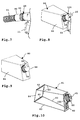
- the connection device 25 comprises, for example, an inlet element 30, which is fastened to the hand-held power tool 10.
- an inlet element 30 which is fastened to the hand-held power tool 10.
- a base body 31 of the inlet element 30, which is tubular is inserted with its connection side 32 into the interior of the suction connection 20.
- a plugging (not shown and realized in a different type of hand-held machine tool), in which therefore the inlet element is plugged from the outside on, for example, a tubular connecting piece of the hand-held machine tool.
- an outlet member 50 is rotatably mounted, which has a likewise tubular base body, namely a base body 51.
- the main body 51 is located with its bearing side 52 of the inlet member 30, while its connection side 53 at its other longitudinal end for connection, for example the suction hose 91 is used or designed.
- the two elements comprising the inlet member 30 and the outlet member 50 are rotatably mounted to each other, for which, however, additionally a connecting element 60 is provided in the form of, for example, a nut.
- a machine portion or connecting portion 35 of the inlet member 30 is inserted into the suction port 20.
- a flange projection 34 projecting radially outward in front of the base body 31 is supported on an end face or free side of the suction connection 20.
- the inlet member 30 is fixed against rotation. This could be realized, for example, by virtue of the fact that the inlet element 30 is adhesively bonded, welded or even in one piece to the suction connection 20. Furthermore, it would be possible to screw the inlet element 30 to the suction connection 20. In the present case, however, the following variant is implemented: anti-rotation means, for example abutment contours 36, are provided on the machine section or connection section 35, for example receptacles or projections which protrude radially inward or radially outward in front of the tubular connection section 35.
- anti-rotation means for example abutment contours 36
- the abutment contours 36 are in engagement with corresponding mating contours on the suction connection 20, for example radially inward into the suction connection 20 projecting, cam-like projections (not shown).
- the inlet member 30 is secured to the housing 11 by it in which the still open base housing 18 is inserted and then the lid 19 not only the dust discharge channel 17, but also a bearing portion 37 covers and thus the bearing portion 37 of the inlet member 30 between the base housing 18 and the lid 19 is clamped, so to speak.
- cooperating counter contours are provided, at least one with one, for example, the in FIG. 5 visible abutment contour 36, cooperating counter contour.
- a bearing section 37 is provided which is provided for supporting the connection element 60 and for coupling to the outlet element 50.
- the connecting element 60 is rotatably mounted on the outlet element 50 on the basis of a rotary bearing 54.
- On the main body 51 of the outlet member 50 is a circumferentially extending rotary bearing projection 55 is provided, namely on a bearing portion 56.
- the pivot bearing projection 55 forms a bearing component of the pivot bearing 54.
- the connecting element 60 has a bearing portion 63, in which a bearing portion 56 of the main body 51st the outlet member 50 engages.
- the connecting element 60 is rotatably mounted externally on the main body 51.
- the two components engage each other, so as to produce a dustproof or at least substantially dustproof connection.
- connection section 57 of the main body 51 or of the outlet element 50 Opposite to the bearing section is a connection section 57 of the main body 51 or of the outlet element 50, to which, for example, the suction hose 91 can be connected by a simple plug-in installation.
- connection portion 57 could also be fixed or pivotally connected to the suction hose 91.
- an arc 58 extends, for example, at an angle of 30-45 °, so that a longitudinal axis L1 of the bearing portion 56 and a longitudinal axis L2 of the terminal portion 57 form an angle. Consequently, it is thus possible to adjust the angle between the longitudinal axes L1 and L2 relative to the inlet element 30 by means of the pivot bearing of the outlet element 50 described in greater detail below.
- the longitudinal axis L1 of the outlet member 50 is, for example, aligned with or parallel to a longitudinal axis of the inlet member 30, while the longitudinal axis L2 occupies an angular position thereto. This or the rotatability of the outlet member 50 relative to the inlet member 30 is indicated by an arrow P in FIG. 6 indicated.
- the connecting element 60 has at its bearing portion 63 a series of circumferentially extending abutment segments 64 which extend parallel to a likewise radially inwardly projecting support rib 65. Between the support ribs 65 and the abutment segments 64 a Drehlageraus originallyung 70 is formed, in which engages the rotating rotary bearing projection 55. In this way, the pivot bearing 54 is formed.
- the mounting of the connector 60 to the outlet member 50 is accomplished by a simple plug-in operation, i. can be realized by plugging the connecting element 60 in the direction of the longitudinal axis L1 to the outlet element 50.
- the abutment segments 64 slide past the rotary bearing projection 55 and engage again at its rear side, so that ultimately the rotary bearing projection 55 comes to lie in the rotary bearing recess 70. Consequently, the connecting element 60 is then rotatably mounted on the outlet element 50.
- the connecting element 60 can be easily grasped and rotated by an operator on the basis of a corrugation 66 arranged on the outside.
- the connecting element 60 On its inner circumference, the connecting element 60 has bayonet cams 61, which can engage with bayonet cams 41 arranged on the outer circumference of the inlet element 30, namely its bearing section 37, when the connecting element 60 is slipped onto the bearing section 37 and thereby twisted.
- the bayonet cams 41, 61 form components of connection means 40 for releasably connecting the outlet member 50 to the inlet member 30.
- the bayonet cams 41, 61 form bayonet contours 71. They are screwed together, so that they also represent screw contours 72 at the same time.
- the bayonet cams 61 project, for example, radially inward in front of a connecting section 62 of the connecting element 60.
- the bearing portion 37 of the inlet member 30 engages the connecting portion 62, wherein by twisting the connecting member 60, the bayonet cams 41, 61 are screwed together.
- a rotation of, for example, an angle of 15-30 ° is sufficient.
- the screwing of the bayonet contours 71 could simultaneously realize a rotational strength of the connecting element 60 on the inlet element 30, for example by a corresponding screwing force, a clamping fit of the bayonet cams 41, 61 to each other or the like.
- locking means 74 are provided as anti-rotation means 73, which on the one hand comprise the bayonet cams 61 of the connecting element 60 and, for another, one or more locking cams 42 on the inlet element 30.
- the bayonet cams 61 slide over the latch cam 42 when bolted to the bayonet cams 41.
- the bayonet cams 61 are pushed completely over the latching cams 42 so that the rear sides of the bayonet cams 61 (rear sides in the direction of rotation) are supported on the front sides of the latching cams 42 are.
- the bayonet cams 61 can only rotate in the release direction when they are first rotated a locking cam 42 over, so be operated against a resistance.
- an anti-rotation or a fuse screwing the fferkonturen 72 is realized.
- the connecting element 60 is screwed to the inlet element 30, the connecting element 60 is secured against rotation on the inlet element 30.
- the outlet element 50 in turn is in turn movably mounted on the connecting element 60, namely on the basis of the rotary bearing 54.
- the outlet element 50 can rotate relative to the inlet element 30.
- this rotation is restricted by form-locking contours 75 provided according to the invention.
- the form-fitting contours 75 comprise a latching structure 45 arranged on an end face 38 of the inlet element 30 and having a plurality of teeth 46.
- a spring arm 68 is provided at the free end of a latching projection 67 is provided for latching or latching with the latching recesses 47 located between the teeth 46 on the inlet member 30.
- the latching structure 45 and the spring arm 68 form components of latching contours 76.
- the spring arm 68 extends substantially in the circumferential direction about the longitudinal axis L1 around, while the latching projection 67 is oriented parallel to the longitudinal axis L1.
- a force direction 69 of the spring arm 68 for actuating the latching projection 67 into the latching recesses 47 thus extends parallel to the longitudinal axis direction L1.
- the longitudinal axis L1 at the same time defines a plug-in axis, along which the outlet element 50 can be connected to the inlet element 30, which is shown in FIG FIG. 4 indicated by an arrow P2.
- the outlet element 50 can thus be finally rotated relative to the inlet member 30, wherein the locking projection 67 on the Locking structure 45 slides along and penetrates into a respective recess 47.
- the locking projection 67 is suitably rounded.
- the locking recesses 47 are suitably rounded.
- An adjusting force for rotating the outlet element 50 relative to the inlet element 30 is expediently smaller than a force which is necessary to rotate the connecting element 60 with respect to the inlet element 30, ie the screw contours 72 against the latching force provided by the latching means 74 and possibly a frictional force between them fferkonturen 72 disengage. It is understood that other types of anti-rotation between the screw contours 72 are possible, for example, a locking slide or the like.
- two spring arms 68 and accordingly two locking projections 67 are provided, with fewer or more such locking means are possible.
- the suction hose 91 is plugged, for example, with a connection piece 92 onto the connection section 57 of the outlet element 50.
- the connection section 57 and / or the connection piece 92 can also be firmly connected to each other or be integral.
- the connection section 57 and / or the connecting piece 92 it is possible for the connection section 57 and / or the connecting piece 92 to be made of rubber or to have a friction-inhibiting coating, so that they can be firmly connected to one another. Consequently, it is preferred if the suction hose 91 can not rotate relative to the outlet element 50, but is held there at least substantially rotationally fixed.
- the so-called only pivot bearing between the outlet member 50 and the inlet member 30 and thus the hand-held power tool 10 is preferably by the between the inlet member 30 and the Exhaust element 50 effective pivot bearing 54 given, but this rotation is inhibited, as explained by the positive locking contours 75.
- form-fitting contours which can be disengaged by a rotation of the inlet element 30 relative to the outlet element 50, namely the abovementioned catch contours 76 represent an option. It is also conceivable that the latching projection or the latching projections 67 are not resiliently provided on the outlet element 50, but fixed there. When the connecting element 60 is then screwed to the inlet element 30, such fixed form-fitting contours come into engagement, so that the respective rotational angular position of the outlet element 50 is fixed in a rotationally fixed manner to the inlet element 30.
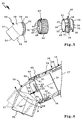
- the dust collecting container 80 is preferably fixed in a predetermined angular position at the rear of the housing 11 of the hand-held machine tool 10, for example, the in FIG. 8 indicated position. However, it may also be advantageous to rotate the dust collecting container 80 relative to the housing 11, for example, so that it has a greater distance to the ground, for example, the workpiece that is processed with the hand-held power tool 10 has.
- the dust collecting container 80 has a frame 81, on whose front side a front plate 82 is provided. On the front plate 82 is an outlet member 150, which in principle has the same function as the outlet member 50. With respect to the dust collecting container 80, the outlet member 150 forms an inlet member, so to speak. Dust conveyed away from the hand machine tool 10 or particles flowing away therefrom, for example sawdust, namely pass through the outlet member 150 into the interior of the dust collecting container 80th
- the outlet member 150 forms an integral part of the front plate 82 is, for example, with these integral or fixedly arranged on this.
- a connecting element 60 that is, the outlet member 150 and the outlet member 50 are substantially identical in construction with the one difference that the outlet member 150 has no free, for example, the suction hose 91 suitable end, but a part of Dust collecting container 80 forms.
- Frame parts 83 extend away from the front plate 82, at the side remote from the front plate 82 a frame 84 is articulated, namely by means of joints 85. Thus, the frame 81 can be folded into a non-use position.
- a dust bag 86 is mounted, which is at least partially permeable to air. Thus, a suction flow away from the hand machine tool 10 may flow through at least one wall of the dust bag 86, but the dust bag 86 retains the dust or other particles in its interior.
- connection device 125 When not in use, the connection device 125, whose other component is the inlet element 30, can be closed, for example, by a cover 88.
- An eyelet 89 is provided on the lid 88, through which a flexible holding member, for example a belt or the like, can be passed to movably connect the lid 88 to the dust collecting container 80 so that the lid 88 can not be lost.
- the lid 88 For closing the inlet of the dust collecting container 80, that is, the outlet element 150, the lid 88 has, for example, a plug-in projection, which in the manner of the bearing section 37 of the Inlet member 30 is configured, that is tubular or at least externally cylindrical and, for example, on its outside bayonet cam 41 has.
- the connecting element 60 can, as it were, make a bayonet connection with the cover 88, in any case screwed to it.
Landscapes
- Engineering & Computer Science (AREA)
- Mechanical Engineering (AREA)
- Electric Vacuum Cleaner (AREA)
- Auxiliary Devices For Machine Tools (AREA)
- Grinding-Machine Dressing And Accessory Apparatuses (AREA)
Claims (14)
- Dispositif de raccordement pour raccorder un système d'évacuation de poussières, en particulier un tuyau flexible d'aspiration (91) ou un contenant de collecte de poussières (80), à une machine-outil manuelle (10) ou à aspirateur (90), dans lequel le dispositif de raccordement (25 ; 125) présente un élément d'entrée (30) de forme tubulaire et un élément de sortie (50) de forme tubulaire, qui sont reliés entre eux par un élément de liaison (60), dans lequel l'élément de sortie (50) et l'élément d'entrée (30) peuvent être tournés l'un par rapport à l'autre, dans lequel des contours à complémentarité de forme (75) venant en prise les uns avec les autres pour fixer l'élément de sortie (50) et l'élément d'entrée (30) sont prévus les uns contre les autres dans au moins deux positions angulaires de rotation entre l'élément d'entrée (30) et l'élément de sortie (50), dans lequel les contours à complémentarité de forme (75) comprennent des contours d'enclenchement (76), qui s'enclenchent les uns dans les autres dans au moins deux positions angulaires de rotation de l'élément d'entrée (30) et de l'élément de sortie (50) l'un par rapport à l'autre, caractérisé en ce que l'élément de sortie (50) et l'élément d'entrée (30) sont maintenus l'un contre l'autre par l'élément de liaison (60), peuvent être tournés toutefois l'un par rapport à l'autre et s'engagent ainsi, l'un par rapport à l'autre, dans les au moins deux positions angulaires de rotation à l'aide des contours d'enclenchement (76).
- Dispositif de raccordement selon la revendication 1, caractérisé en ce que l'élément de liaison (60) comprend des moyens de liaison (40) pour relier de manière amovible l'élément de sortie (50) à l'élément d'entrée (30).
- Dispositif de raccordement selon la revendication 1 ou 2, caractérisé en ce que les contours à complémentarité de forme (75) sont disposés au niveau de l'élément de sortie (50) et au niveau de l'élément d'entrée (30) et se trouvent en prise l'un avec l'autre le long de l'élément de liaison (60), en particulier à travers l'élément de liaison (60) quand l'élément de liaison (60) relie l'élément de sortie (50) et l'élément d'entrée (30) l'un à l'autre.
- Dispositif de raccordement selon l'une quelconque des revendications précédentes, caractérisé en ce que les contours d'enclenchement (76) présentent une partie faisant saillie d'enclenchement (67) disposée au niveau d'un bras à ressorts (68) sur ressorts, laquelle est disposée au niveau de l'un des éléments parmi l'élément de sortie (50) ou l'élément d'entrée (30) et qui vient en prise par enclenchement dans des renfoncements d'enclenchement au niveau de l'autre élément parmi l'élément de sortie (50) ou l'élément d'entrée (30).
- Dispositif de raccordement selon la revendication 4, caractérisé en ce que les renfoncements d'enclenchement et/ou le bras à ressorts (68) sont disposés au niveau d'un côté frontal de l'élément de sortie (50) respectif ou de l'élément d'entrée (30), et/ou en ce que les renfoncements d'enclenchement et la partie faisant saillie d'enclenchement (67) disposée en particulier au niveau d'un bras à ressorts (68) sont configurés, aux fins d'un actionnement d'enclenchement axial, de manière parallèle par rapport à l'axe longitudinal ou le long de l'axe longitudinal de l'élément de sortie (50) ou de l'élément d'entrée (30).
- Elément de raccordement selon l'une quelconque des revendications précédentes, caractérisé en ce que l'élément de sortie (50) et/ou l'élément d'entrée (30) et/ou l'élément de liaison (60) présentent une section de courbure ou un arc (58).
- Dispositif de raccordement selon l'une quelconque des revendications précédentes, caractérisé en ce que l'élément de liaison (60) comprenant en particulier un écrou peut être vissé à l'aide de contours à visser (72) ou peut être enclenché à l'aide de contours d'enclenchement (76) à au moins un des éléments parmi l'élément de sortie (50) ou l'élément d'entrée (30).
- Dispositif de raccordement selon la revendication 7, caractérisé en ce que les contours à visser (72) comprennent des contours à baïonnette (71) ou sont formés par des contours à baïonnette (71).
- Dispositif de raccordement selon la revendication 7 ou 8, caractérisé en ce que des moyens d'enclenchement (74) comprenant en particulier un ergot d'enclenchement sont associés à des contours à visser (72), lesquels moyens d'enclenchement parviennent en prise, lors d'un vissage des contours à visser (72) les uns aux autres, afin de bloquer en rotation le vissage.
- Dispositif de raccordement selon l'une quelconque des revendications précédentes, caractérisé en ce que l'élément de liaison (60) est logé de manière à pouvoir tourner au niveau de l'un des éléments parmi l'élément de sortie (50) ou l'élément d'entrée (30) à l'aide d'un palier rotatif (54), qui forme en particulier le ou un palier rotatif entre l'élément de sortie (50) et l'élément d'entrée (30), et/ou en ce que l'élément de liaison (60) peut être fixé de manière bloquée en rotation à l'aide de moyens de blocage en rotation au niveau de l'un des éléments parmi l'élément de sortie (50) ou l'élément d'entrée (30).
- Dispositif de raccordement selon la revendication 10, caractérisé en ce que l'élément de liaison (60) peut être monté à l'aide d'un montage par emboîtement au niveau de l'élément respectif parmi l'élément de sortie (50) ou l'élément d'entrée (30), dans lequel le palier rotatif (54) présente des composants formant paliers configurés sous la forme d'éléments d'enclenchement, lesquels parviennent en prise les uns avec les autres lors du montage par emboîtement et forment le palier rotatif (54).
- Dispositif de raccordement selon la revendication 10 ou 11, caractérisé en ce que l'élément de liaison (60) et l'élément respectif parmi l'élément de sortie (50) ou l'élément d'entrée (30) viennent en prise entre eux par des sections de palier de forme tubulaire, dans lequel le palier rotatif (54) comprend au moins une partie faisant saillie de palier rotatif (55) s'étendant dans la direction périphérique au niveau d'un corps comprenant l'élément de liaison (60) et l'élément de sortie (50) ou l'élément d'entrée (30) et faisant saillie à la manière d'une bride vers l'intérieur radialement ou vers l'extérieur radialement, laquelle partie faisant saillie de palier rotatif vient en prise avec un évidement de palier rotatif (70) s'étendant de la même manière dans la direction périphérique au niveau de l'autre corps comprenant l'élément de liaison (60) et l'élément de sortie (50) ou l'élément d'entrée (30).
- Dispositif de raccordement selon la revendication 12, caractérisé en ce que la partie faisant saillie de palier rotatif (55) et/ou l'évidement de palier rotatif (70) sont segmentés.
- Machine-outil manuelle (10) ou tuyau flexible d'aspiration (91) ou contenant collecteur de poussières (80), comprenant un dispositif de raccordement (25; 125) selon l'une quelconque des revendications précédentes.
Applications Claiming Priority (1)
| Application Number | Priority Date | Filing Date | Title |
|---|---|---|---|
| DE102014001349.9A DE102014001349A1 (de) | 2014-02-01 | 2014-02-01 | Anschlussvorrichtung für eine Staubabfuhreinrichtung und eine Hand-Werkzeugmaschine |
Publications (3)
| Publication Number | Publication Date |
|---|---|
| EP2902155A2 EP2902155A2 (fr) | 2015-08-05 |
| EP2902155A3 EP2902155A3 (fr) | 2015-08-26 |
| EP2902155B1 true EP2902155B1 (fr) | 2016-11-09 |
Family
ID=52345052
Family Applications (1)
| Application Number | Title | Priority Date | Filing Date |
|---|---|---|---|
| EP15150408.1A Active EP2902155B1 (fr) | 2014-02-01 | 2015-01-08 | Dispositif de raccordement pour un dispositif d'évacuation de poussière et machine-outil portative |
Country Status (2)
| Country | Link |
|---|---|
| EP (1) | EP2902155B1 (fr) |
| DE (1) | DE102014001349A1 (fr) |
Cited By (4)
| Publication number | Priority date | Publication date | Assignee | Title |
|---|---|---|---|---|
| EP4454822A1 (fr) * | 2023-04-26 | 2024-10-30 | Festool GmbH | Réceptacle collecteur pour particules de pièce, ensemble outil électrique portatif, ensemble collecteur de particules, système d'outil électrique portatif et utilisation d'un rail de guidage |
| EP4454821A1 (fr) * | 2023-04-26 | 2024-10-30 | Festool GmbH | Réceptacle collecteur pour particules de pièce, ensemble outil électrique portatif et procédés de couplage et de découplage |
| WO2024223689A1 (fr) * | 2023-04-26 | 2024-10-31 | Festool Gmbh | Récipient collecteur pour particules de pièce, ensemble comprenant un outil portatif entraîné par moteur et un récipient collecteur, outil portatif entraîné par moteur et procédé |
| US12516763B2 (en) | 2024-04-23 | 2026-01-06 | Festool Gmbh | Connector for coupling a particle outlet of a handheld machine tool to a particle receiving device, handheld machine tool, handheld machine tool assembly, and method |
Families Citing this family (9)
| Publication number | Priority date | Publication date | Assignee | Title |
|---|---|---|---|---|
| DE102015222159A1 (de) * | 2015-11-11 | 2017-05-11 | Robert Bosch Gmbh | Koppelmittel für eine Werkzeugmaschine |
| EP3178614A1 (fr) * | 2015-12-11 | 2017-06-14 | HILTI Aktiengesellschaft | Dispositif de raccordement |
| DE102016105330A1 (de) | 2016-03-22 | 2017-09-28 | Festool Gmbh | Staubsammelvorrichtung mit einer Stützeinrichtung |
| DE102016105331A1 (de) | 2016-03-22 | 2017-09-28 | Festool Gmbh | Staubsammelvorrichtung mit einem Deckel für eine Hand-Werkzeugmaschine |
| DE102020208343A1 (de) * | 2020-07-03 | 2022-01-05 | Robert Bosch Gesellschaft mit beschränkter Haftung | Adapter sowie Handwerkzeugmaschinensystem mit einer Handwerkzeugmaschine und einem Adapter |
| CN112091899B (zh) * | 2020-09-25 | 2023-06-27 | 国网福建省电力有限公司厦门供电公司 | 一种无尘环保型电锤 |
| DE102023203889A1 (de) * | 2023-04-26 | 2024-10-31 | Festool Gmbh | Auffangbehältnis für Werkstückpartikel, Baugruppe umfassend ein motorisch angetriebenes Handwerkzeug und ein Auffangbehältnis sowie motorisch angetriebenes Handwerkzeug |
| DE102024114134A1 (de) * | 2024-02-09 | 2025-08-14 | Festool Gmbh | Staubabfuhrvorrichtung für eine Schleifmaschine |
| EP4599984A3 (fr) * | 2024-02-09 | 2026-01-07 | Festool GmbH | Dispositif d'évacuation de poussière pour une machine à meuler |
Family Cites Families (7)
| Publication number | Priority date | Publication date | Assignee | Title |
|---|---|---|---|---|
| GB387011A (en) * | 1931-05-20 | 1933-01-24 | Air Way Electric Appl Corp | Improvements in bag couplings for suction cleaners |
| US2421228A (en) * | 1944-10-30 | 1947-05-27 | Gilbert E White | Hose coupling |
| EP0233710A1 (fr) * | 1986-01-22 | 1987-08-26 | Numatic International Limited | Accessoires pour les tuyaux flexibles |
| DE4142497A1 (de) * | 1991-12-21 | 1993-06-24 | Bosch Gmbh Robert | Handwerkzeugmashine mit geblaese |
| JP3755627B2 (ja) * | 1997-10-30 | 2006-03-15 | 東芝テック株式会社 | 延長管および電気掃除機 |
| DE102007008388A1 (de) * | 2007-02-21 | 2008-08-28 | Festool Gmbh | Vorrichtung zum Verbinden einer Werkstück-Bearbeitungsmaschine mit einem Absaugschlauch |
| JP5278855B2 (ja) * | 2008-09-01 | 2013-09-04 | 株式会社やまびこ | パイプ連結構造 |
-
2014
- 2014-02-01 DE DE102014001349.9A patent/DE102014001349A1/de active Pending
-
2015
- 2015-01-08 EP EP15150408.1A patent/EP2902155B1/fr active Active
Non-Patent Citations (1)
| Title |
|---|
| None * |
Cited By (6)
| Publication number | Priority date | Publication date | Assignee | Title |
|---|---|---|---|---|
| EP4454822A1 (fr) * | 2023-04-26 | 2024-10-30 | Festool GmbH | Réceptacle collecteur pour particules de pièce, ensemble outil électrique portatif, ensemble collecteur de particules, système d'outil électrique portatif et utilisation d'un rail de guidage |
| EP4454821A1 (fr) * | 2023-04-26 | 2024-10-30 | Festool GmbH | Réceptacle collecteur pour particules de pièce, ensemble outil électrique portatif et procédés de couplage et de découplage |
| WO2024223693A1 (fr) * | 2023-04-26 | 2024-10-31 | Festool Gmbh | Réceptacle de collecte pour particules de pièce à travailler, ensemble outil électrique portatif, procédés d'accouplement et de désaccouplement d'un réceptacle de collecte pour particules de pièce à travailler à un outil électrique portatif ou à partir d'un outil électrique portatif, procédé de transport d'un ensemble outil électrique portatif |
| WO2024223689A1 (fr) * | 2023-04-26 | 2024-10-31 | Festool Gmbh | Récipient collecteur pour particules de pièce, ensemble comprenant un outil portatif entraîné par moteur et un récipient collecteur, outil portatif entraîné par moteur et procédé |
| WO2024223694A1 (fr) * | 2023-04-26 | 2024-10-31 | Festool Gmbh | Réceptacle de collecte pour des particules de pièce à travailler, ensemble outil électrique portatif, ensemble de collecte de particules, système d'outil électrique portatif et utilisation d'un rail de guidage |
| US12516763B2 (en) | 2024-04-23 | 2026-01-06 | Festool Gmbh | Connector for coupling a particle outlet of a handheld machine tool to a particle receiving device, handheld machine tool, handheld machine tool assembly, and method |
Also Published As
| Publication number | Publication date |
|---|---|
| EP2902155A2 (fr) | 2015-08-05 |
| DE102014001349A1 (de) | 2015-08-06 |
| EP2902155A3 (fr) | 2015-08-26 |
Similar Documents
| Publication | Publication Date | Title |
|---|---|---|
| EP2902155B1 (fr) | Dispositif de raccordement pour un dispositif d'évacuation de poussière et machine-outil portative | |
| DE102012207571B4 (de) | Abdeckvorrichtung mit Staubabsaugung bei Verwendung mit einem Elektrowerkzeug | |
| DE102005063017B4 (de) | Handgeführtes Elektrowerkzeug mit einer Schutzhaube | |
| EP2965865B1 (fr) | Appareil de séparation manuel | |
| DE102007012394A1 (de) | Griffstab einer handgeführten Werkzeugmaschine | |
| EP3235602B1 (fr) | Dispositif de collecte de poussière comprenant un moyen de support | |
| EP2383076A2 (fr) | Appareil auxiliaire pour une machine-outil manuelle et machine-outil manuelle en étant équipée | |
| EP4204174B1 (fr) | Scie manuelle portable pourvue d'un dispositif d'aspiration | |
| EP1714740B1 (fr) | Tronçonneuse à meule | |
| DE102014002045A1 (de) | Fräsvorrichtung | |
| DE102012020546B4 (de) | Saugschlauch mit einem Schlauchanschlussstück und Staubsauger mit einem Saugschlauch | |
| EP3209464B1 (fr) | Machine-outil portative pourvue d'un porte-outil sds | |
| EP0548782A1 (fr) | Outillage à main avec un sac à poussière | |
| DE102009001502A1 (de) | Handwerkzeugmaschinenvorrichtung | |
| EP2915639A1 (fr) | Dispositif de machines-outils | |
| EP3235603A2 (fr) | Dispositif de collecte de poussière comprenant un couvercle pour une machine-outil manuelle | |
| DE3843912A1 (de) | Elektrohandwerkzeug mit spaenekanal und absaugstutzen | |
| EP2106327A1 (fr) | Machine-outil à main | |
| EP3185742B1 (fr) | Buse d'aspiration et aspirateur pour surfaces dures | |
| EP0558893A2 (fr) | Outillage à main motorisé pour rectifier, polir, dérouiller ou pour traitement de surface du genre | |
| DE102004025880B3 (de) | Absaugeinrichtung für Elektrohandwerkzeuggeräte | |
| DE102010042433A1 (de) | Werkzeugmaschine, insbesondere Handwerkzeugmaschine | |
| DE102014200401B4 (de) | Schleifwerkzeug mit einem Schleifkörper mit innenliegendem Antrieb | |
| EP1429890A1 (fr) | Machine-outil portative munie d'une boite pour la poussiere | |
| DE19821705A1 (de) | Sauggerät zum Ansaugen von Schmutz o. dgl. enthaltendem Sauggut |
Legal Events
| Date | Code | Title | Description |
|---|---|---|---|
| PUAL | Search report despatched |
Free format text: ORIGINAL CODE: 0009013 |
|
| PUAI | Public reference made under article 153(3) epc to a published international application that has entered the european phase |
Free format text: ORIGINAL CODE: 0009012 |
|
| 17P | Request for examination filed |
Effective date: 20150108 |
|
| AK | Designated contracting states |
Kind code of ref document: A2 Designated state(s): AL AT BE BG CH CY CZ DE DK EE ES FI FR GB GR HR HU IE IS IT LI LT LU LV MC MK MT NL NO PL PT RO RS SE SI SK SM TR |
|
| AX | Request for extension of the european patent |
Extension state: BA ME |
|
| AK | Designated contracting states |
Kind code of ref document: A3 Designated state(s): AL AT BE BG CH CY CZ DE DK EE ES FI FR GB GR HR HU IE IS IT LI LT LU LV MC MK MT NL NO PL PT RO RS SE SI SK SM TR |
|
| AX | Request for extension of the european patent |
Extension state: BA ME |
|
| RIC1 | Information provided on ipc code assigned before grant |
Ipc: B25F 5/00 20060101AFI20150720BHEP |
|
| 17P | Request for examination filed |
Effective date: 20160203 |
|
| RBV | Designated contracting states (corrected) |
Designated state(s): AL AT BE BG CH CY CZ DE DK EE ES FI FR GB GR HR HU IE IS IT LI LT LU LV MC MK MT NL NO PL PT RO RS SE SI SK SM TR |
|
| 17Q | First examination report despatched |
Effective date: 20160525 |
|
| GRAP | Despatch of communication of intention to grant a patent |
Free format text: ORIGINAL CODE: EPIDOSNIGR1 |
|
| RIC1 | Information provided on ipc code assigned before grant |
Ipc: B25F 5/00 20060101AFI20160629BHEP Ipc: B24B 55/06 20060101ALI20160629BHEP |
|
| INTG | Intention to grant announced |
Effective date: 20160714 |
|
| GRAS | Grant fee paid |
Free format text: ORIGINAL CODE: EPIDOSNIGR3 |
|
| GRAA | (expected) grant |
Free format text: ORIGINAL CODE: 0009210 |
|
| AK | Designated contracting states |
Kind code of ref document: B1 Designated state(s): AL AT BE BG CH CY CZ DE DK EE ES FI FR GB GR HR HU IE IS IT LI LT LU LV MC MK MT NL NO PL PT RO RS SE SI SK SM TR |
|
| REG | Reference to a national code |
Ref country code: GB Ref legal event code: FG4D Free format text: NOT ENGLISH Ref country code: FR Ref legal event code: PLFP Year of fee payment: 3 |
|
| REG | Reference to a national code |
Ref country code: AT Ref legal event code: REF Ref document number: 843455 Country of ref document: AT Kind code of ref document: T Effective date: 20161115 Ref country code: CH Ref legal event code: EP |
|
| REG | Reference to a national code |
Ref country code: IE Ref legal event code: FG4D Free format text: LANGUAGE OF EP DOCUMENT: GERMAN |
|
| REG | Reference to a national code |
Ref country code: DE Ref legal event code: R096 Ref document number: 502015000281 Country of ref document: DE |
|
| PG25 | Lapsed in a contracting state [announced via postgrant information from national office to epo] |
Ref country code: LV Free format text: LAPSE BECAUSE OF FAILURE TO SUBMIT A TRANSLATION OF THE DESCRIPTION OR TO PAY THE FEE WITHIN THE PRESCRIBED TIME-LIMIT Effective date: 20161109 |
|
| REG | Reference to a national code |
Ref country code: LT Ref legal event code: MG4D |
|
| REG | Reference to a national code |
Ref country code: NL Ref legal event code: MP Effective date: 20161109 |
|
| PG25 | Lapsed in a contracting state [announced via postgrant information from national office to epo] |
Ref country code: GR Free format text: LAPSE BECAUSE OF FAILURE TO SUBMIT A TRANSLATION OF THE DESCRIPTION OR TO PAY THE FEE WITHIN THE PRESCRIBED TIME-LIMIT Effective date: 20170210 Ref country code: NL Free format text: LAPSE BECAUSE OF FAILURE TO SUBMIT A TRANSLATION OF THE DESCRIPTION OR TO PAY THE FEE WITHIN THE PRESCRIBED TIME-LIMIT Effective date: 20161109 Ref country code: LT Free format text: LAPSE BECAUSE OF FAILURE TO SUBMIT A TRANSLATION OF THE DESCRIPTION OR TO PAY THE FEE WITHIN THE PRESCRIBED TIME-LIMIT Effective date: 20161109 Ref country code: SE Free format text: LAPSE BECAUSE OF FAILURE TO SUBMIT A TRANSLATION OF THE DESCRIPTION OR TO PAY THE FEE WITHIN THE PRESCRIBED TIME-LIMIT Effective date: 20161109 Ref country code: NO Free format text: LAPSE BECAUSE OF FAILURE TO SUBMIT A TRANSLATION OF THE DESCRIPTION OR TO PAY THE FEE WITHIN THE PRESCRIBED TIME-LIMIT Effective date: 20170209 |
|
| PG25 | Lapsed in a contracting state [announced via postgrant information from national office to epo] |
Ref country code: HR Free format text: LAPSE BECAUSE OF FAILURE TO SUBMIT A TRANSLATION OF THE DESCRIPTION OR TO PAY THE FEE WITHIN THE PRESCRIBED TIME-LIMIT Effective date: 20161109 Ref country code: ES Free format text: LAPSE BECAUSE OF FAILURE TO SUBMIT A TRANSLATION OF THE DESCRIPTION OR TO PAY THE FEE WITHIN THE PRESCRIBED TIME-LIMIT Effective date: 20161109 Ref country code: RS Free format text: LAPSE BECAUSE OF FAILURE TO SUBMIT A TRANSLATION OF THE DESCRIPTION OR TO PAY THE FEE WITHIN THE PRESCRIBED TIME-LIMIT Effective date: 20161109 Ref country code: FI Free format text: LAPSE BECAUSE OF FAILURE TO SUBMIT A TRANSLATION OF THE DESCRIPTION OR TO PAY THE FEE WITHIN THE PRESCRIBED TIME-LIMIT Effective date: 20161109 Ref country code: IS Free format text: LAPSE BECAUSE OF FAILURE TO SUBMIT A TRANSLATION OF THE DESCRIPTION OR TO PAY THE FEE WITHIN THE PRESCRIBED TIME-LIMIT Effective date: 20170309 Ref country code: PL Free format text: LAPSE BECAUSE OF FAILURE TO SUBMIT A TRANSLATION OF THE DESCRIPTION OR TO PAY THE FEE WITHIN THE PRESCRIBED TIME-LIMIT Effective date: 20161109 Ref country code: PT Free format text: LAPSE BECAUSE OF FAILURE TO SUBMIT A TRANSLATION OF THE DESCRIPTION OR TO PAY THE FEE WITHIN THE PRESCRIBED TIME-LIMIT Effective date: 20170309 Ref country code: BE Free format text: LAPSE BECAUSE OF NON-PAYMENT OF DUE FEES Effective date: 20170131 |
|
| PG25 | Lapsed in a contracting state [announced via postgrant information from national office to epo] |
Ref country code: SK Free format text: LAPSE BECAUSE OF FAILURE TO SUBMIT A TRANSLATION OF THE DESCRIPTION OR TO PAY THE FEE WITHIN THE PRESCRIBED TIME-LIMIT Effective date: 20161109 Ref country code: DK Free format text: LAPSE BECAUSE OF FAILURE TO SUBMIT A TRANSLATION OF THE DESCRIPTION OR TO PAY THE FEE WITHIN THE PRESCRIBED TIME-LIMIT Effective date: 20161109 Ref country code: CZ Free format text: LAPSE BECAUSE OF FAILURE TO SUBMIT A TRANSLATION OF THE DESCRIPTION OR TO PAY THE FEE WITHIN THE PRESCRIBED TIME-LIMIT Effective date: 20161109 Ref country code: EE Free format text: LAPSE BECAUSE OF FAILURE TO SUBMIT A TRANSLATION OF THE DESCRIPTION OR TO PAY THE FEE WITHIN THE PRESCRIBED TIME-LIMIT Effective date: 20161109 Ref country code: RO Free format text: LAPSE BECAUSE OF FAILURE TO SUBMIT A TRANSLATION OF THE DESCRIPTION OR TO PAY THE FEE WITHIN THE PRESCRIBED TIME-LIMIT Effective date: 20161109 |
|
| REG | Reference to a national code |
Ref country code: DE Ref legal event code: R097 Ref document number: 502015000281 Country of ref document: DE |
|
| PG25 | Lapsed in a contracting state [announced via postgrant information from national office to epo] |
Ref country code: BG Free format text: LAPSE BECAUSE OF FAILURE TO SUBMIT A TRANSLATION OF THE DESCRIPTION OR TO PAY THE FEE WITHIN THE PRESCRIBED TIME-LIMIT Effective date: 20170209 Ref country code: IT Free format text: LAPSE BECAUSE OF FAILURE TO SUBMIT A TRANSLATION OF THE DESCRIPTION OR TO PAY THE FEE WITHIN THE PRESCRIBED TIME-LIMIT Effective date: 20161109 Ref country code: SM Free format text: LAPSE BECAUSE OF FAILURE TO SUBMIT A TRANSLATION OF THE DESCRIPTION OR TO PAY THE FEE WITHIN THE PRESCRIBED TIME-LIMIT Effective date: 20161109 |
|
| PLBE | No opposition filed within time limit |
Free format text: ORIGINAL CODE: 0009261 |
|
| STAA | Information on the status of an ep patent application or granted ep patent |
Free format text: STATUS: NO OPPOSITION FILED WITHIN TIME LIMIT |
|
| PG25 | Lapsed in a contracting state [announced via postgrant information from national office to epo] |
Ref country code: MC Free format text: LAPSE BECAUSE OF FAILURE TO SUBMIT A TRANSLATION OF THE DESCRIPTION OR TO PAY THE FEE WITHIN THE PRESCRIBED TIME-LIMIT Effective date: 20161109 |
|
| 26N | No opposition filed |
Effective date: 20170810 |
|
| REG | Reference to a national code |
Ref country code: IE Ref legal event code: MM4A |
|
| REG | Reference to a national code |
Ref country code: FR Ref legal event code: PLFP Year of fee payment: 4 |
|
| PG25 | Lapsed in a contracting state [announced via postgrant information from national office to epo] |
Ref country code: LU Free format text: LAPSE BECAUSE OF NON-PAYMENT OF DUE FEES Effective date: 20170108 Ref country code: SI Free format text: LAPSE BECAUSE OF FAILURE TO SUBMIT A TRANSLATION OF THE DESCRIPTION OR TO PAY THE FEE WITHIN THE PRESCRIBED TIME-LIMIT Effective date: 20161109 |
|
| REG | Reference to a national code |
Ref country code: BE Ref legal event code: MM Effective date: 20170131 |
|
| PG25 | Lapsed in a contracting state [announced via postgrant information from national office to epo] |
Ref country code: IE Free format text: LAPSE BECAUSE OF NON-PAYMENT OF DUE FEES Effective date: 20170108 |
|
| REG | Reference to a national code |
Ref country code: CH Ref legal event code: PL |
|
| PG25 | Lapsed in a contracting state [announced via postgrant information from national office to epo] |
Ref country code: MT Free format text: LAPSE BECAUSE OF FAILURE TO SUBMIT A TRANSLATION OF THE DESCRIPTION OR TO PAY THE FEE WITHIN THE PRESCRIBED TIME-LIMIT Effective date: 20161109 |
|
| REG | Reference to a national code |
Ref country code: FR Ref legal event code: PLFP Year of fee payment: 5 |
|
| PG25 | Lapsed in a contracting state [announced via postgrant information from national office to epo] |
Ref country code: CH Free format text: LAPSE BECAUSE OF NON-PAYMENT OF DUE FEES Effective date: 20180131 Ref country code: LI Free format text: LAPSE BECAUSE OF NON-PAYMENT OF DUE FEES Effective date: 20180131 |
|
| PG25 | Lapsed in a contracting state [announced via postgrant information from national office to epo] |
Ref country code: HU Free format text: LAPSE BECAUSE OF FAILURE TO SUBMIT A TRANSLATION OF THE DESCRIPTION OR TO PAY THE FEE WITHIN THE PRESCRIBED TIME-LIMIT; INVALID AB INITIO Effective date: 20150108 |
|
| PG25 | Lapsed in a contracting state [announced via postgrant information from national office to epo] |
Ref country code: CY Free format text: LAPSE BECAUSE OF FAILURE TO SUBMIT A TRANSLATION OF THE DESCRIPTION OR TO PAY THE FEE WITHIN THE PRESCRIBED TIME-LIMIT Effective date: 20161109 |
|
| PG25 | Lapsed in a contracting state [announced via postgrant information from national office to epo] |
Ref country code: MK Free format text: LAPSE BECAUSE OF FAILURE TO SUBMIT A TRANSLATION OF THE DESCRIPTION OR TO PAY THE FEE WITHIN THE PRESCRIBED TIME-LIMIT Effective date: 20161109 |
|
| PG25 | Lapsed in a contracting state [announced via postgrant information from national office to epo] |
Ref country code: TR Free format text: LAPSE BECAUSE OF FAILURE TO SUBMIT A TRANSLATION OF THE DESCRIPTION OR TO PAY THE FEE WITHIN THE PRESCRIBED TIME-LIMIT Effective date: 20161109 |
|
| PG25 | Lapsed in a contracting state [announced via postgrant information from national office to epo] |
Ref country code: AL Free format text: LAPSE BECAUSE OF FAILURE TO SUBMIT A TRANSLATION OF THE DESCRIPTION OR TO PAY THE FEE WITHIN THE PRESCRIBED TIME-LIMIT Effective date: 20161109 |
|
| REG | Reference to a national code |
Ref country code: AT Ref legal event code: MM01 Ref document number: 843455 Country of ref document: AT Kind code of ref document: T Effective date: 20200108 |
|
| PG25 | Lapsed in a contracting state [announced via postgrant information from national office to epo] |
Ref country code: AT Free format text: LAPSE BECAUSE OF NON-PAYMENT OF DUE FEES Effective date: 20200108 |
|
| P01 | Opt-out of the competence of the unified patent court (upc) registered |
Effective date: 20230517 |
|
| PGFP | Annual fee paid to national office [announced via postgrant information from national office to epo] |
Ref country code: GB Payment date: 20251208 Year of fee payment: 12 |
|
| PGFP | Annual fee paid to national office [announced via postgrant information from national office to epo] |
Ref country code: FR Payment date: 20251208 Year of fee payment: 12 |
|
| PGFP | Annual fee paid to national office [announced via postgrant information from national office to epo] |
Ref country code: DE Payment date: 20251209 Year of fee payment: 12 |