EP2902165B1 - Verfahren zur Herstellung eines Stangenelements und Stangenelement - Google Patents
Verfahren zur Herstellung eines Stangenelements und Stangenelement Download PDFInfo
- Publication number
- EP2902165B1 EP2902165B1 EP15153731.3A EP15153731A EP2902165B1 EP 2902165 B1 EP2902165 B1 EP 2902165B1 EP 15153731 A EP15153731 A EP 15153731A EP 2902165 B1 EP2902165 B1 EP 2902165B1
- Authority
- EP
- European Patent Office
- Prior art keywords
- peripheral face
- metal
- outer peripheral
- pipe
- metal ring
- Prior art date
- Legal status (The legal status is an assumption and is not a legal conclusion. Google has not performed a legal analysis and makes no representation as to the accuracy of the status listed.)
- Not-in-force
Links
- 238000004519 manufacturing process Methods 0.000 title claims description 18
- 239000002184 metal Substances 0.000 claims description 216
- 230000002093 peripheral effect Effects 0.000 claims description 106
- 239000003365 glass fiber Substances 0.000 claims description 67
- 229920000049 Carbon (fiber) Polymers 0.000 claims description 63
- 239000004917 carbon fiber Substances 0.000 claims description 63
- VNWKTOKETHGBQD-UHFFFAOYSA-N methane Chemical compound C VNWKTOKETHGBQD-UHFFFAOYSA-N 0.000 claims description 47
- 238000004804 winding Methods 0.000 claims description 33
- 238000000034 method Methods 0.000 claims description 22
- 229920005989 resin Polymers 0.000 claims description 21
- 239000011347 resin Substances 0.000 claims description 21
- 239000004744 fabric Substances 0.000 claims description 19
- 239000004745 nonwoven fabric Substances 0.000 claims description 12
- 238000007788 roughening Methods 0.000 claims description 5
- 238000003754 machining Methods 0.000 description 10
- 230000008569 process Effects 0.000 description 8
- 229920002430 Fibre-reinforced plastic Polymers 0.000 description 7
- 239000011151 fibre-reinforced plastic Substances 0.000 description 7
- 239000004918 carbon fiber reinforced polymer Substances 0.000 description 5
- 230000000052 comparative effect Effects 0.000 description 5
- 230000004048 modification Effects 0.000 description 5
- 238000012986 modification Methods 0.000 description 5
- 239000011521 glass Substances 0.000 description 4
- 239000000463 material Substances 0.000 description 4
- 210000002445 nipple Anatomy 0.000 description 3
- 238000010791 quenching Methods 0.000 description 3
- 230000000171 quenching effect Effects 0.000 description 3
- 239000012260 resinous material Substances 0.000 description 3
- 238000009941 weaving Methods 0.000 description 3
- 239000013585 weight reducing agent Substances 0.000 description 3
- 229910003460 diamond Inorganic materials 0.000 description 2
- 239000010432 diamond Substances 0.000 description 2
- 239000000835 fiber Substances 0.000 description 2
- 239000003733 fiber-reinforced composite Substances 0.000 description 2
- 239000002657 fibrous material Substances 0.000 description 2
- 239000010410 layer Substances 0.000 description 2
- 229920001187 thermosetting polymer Polymers 0.000 description 2
- XQUPVDVFXZDTLT-UHFFFAOYSA-N 1-[4-[[4-(2,5-dioxopyrrol-1-yl)phenyl]methyl]phenyl]pyrrole-2,5-dione Chemical compound O=C1C=CC(=O)N1C(C=C1)=CC=C1CC1=CC=C(N2C(C=CC2=O)=O)C=C1 XQUPVDVFXZDTLT-UHFFFAOYSA-N 0.000 description 1
- 229910000975 Carbon steel Inorganic materials 0.000 description 1
- 229910000831 Steel Inorganic materials 0.000 description 1
- 239000002253 acid Substances 0.000 description 1
- 239000012790 adhesive layer Substances 0.000 description 1
- 238000004873 anchoring Methods 0.000 description 1
- 239000004760 aramid Substances 0.000 description 1
- 229920006231 aramid fiber Polymers 0.000 description 1
- 238000005422 blasting Methods 0.000 description 1
- 239000010962 carbon steel Substances 0.000 description 1
- 238000005255 carburizing Methods 0.000 description 1
- 239000002131 composite material Substances 0.000 description 1
- 238000001816 cooling Methods 0.000 description 1
- 230000008878 coupling Effects 0.000 description 1
- 238000010168 coupling process Methods 0.000 description 1
- 238000005859 coupling reaction Methods 0.000 description 1
- 238000005520 cutting process Methods 0.000 description 1
- 230000007613 environmental effect Effects 0.000 description 1
- 239000003822 epoxy resin Substances 0.000 description 1
- 238000005530 etching Methods 0.000 description 1
- 238000007646 gravure printing Methods 0.000 description 1
- 230000006872 improvement Effects 0.000 description 1
- 238000010030 laminating Methods 0.000 description 1
- 238000010329 laser etching Methods 0.000 description 1
- 230000007246 mechanism Effects 0.000 description 1
- 239000002245 particle Substances 0.000 description 1
- 239000004033 plastic Substances 0.000 description 1
- 229920003023 plastic Polymers 0.000 description 1
- 229920003192 poly(bis maleimide) Polymers 0.000 description 1
- 229920000647 polyepoxide Polymers 0.000 description 1
- 229920001721 polyimide Polymers 0.000 description 1
- 239000009719 polyimide resin Substances 0.000 description 1
- 238000002360 preparation method Methods 0.000 description 1
- 102200082816 rs34868397 Human genes 0.000 description 1
- 239000010959 steel Substances 0.000 description 1
- 229920003002 synthetic resin Polymers 0.000 description 1
- 239000000057 synthetic resin Substances 0.000 description 1
- 229920006337 unsaturated polyester resin Polymers 0.000 description 1
Images


Classifications
-
- B—PERFORMING OPERATIONS; TRANSPORTING
- B29—WORKING OF PLASTICS; WORKING OF SUBSTANCES IN A PLASTIC STATE IN GENERAL
- B29C—SHAPING OR JOINING OF PLASTICS; SHAPING OF MATERIAL IN A PLASTIC STATE, NOT OTHERWISE PROVIDED FOR; AFTER-TREATMENT OF THE SHAPED PRODUCTS, e.g. REPAIRING
- B29C70/00—Shaping composites, i.e. plastics material comprising reinforcements, fillers or preformed parts, e.g. inserts
- B29C70/04—Shaping composites, i.e. plastics material comprising reinforcements, fillers or preformed parts, e.g. inserts comprising reinforcements only, e.g. self-reinforcing plastics
- B29C70/28—Shaping operations therefor
- B29C70/30—Shaping by lay-up, i.e. applying fibres, tape or broadsheet on a mould, former or core; Shaping by spray-up, i.e. spraying of fibres on a mould, former or core
- B29C70/32—Shaping by lay-up, i.e. applying fibres, tape or broadsheet on a mould, former or core; Shaping by spray-up, i.e. spraying of fibres on a mould, former or core on a rotating mould, former or core
-
- B—PERFORMING OPERATIONS; TRANSPORTING
- B62—LAND VEHICLES FOR TRAVELLING OTHERWISE THAN ON RAILS
- B62D—MOTOR VEHICLES; TRAILERS
- B62D3/00—Steering gears
- B62D3/02—Steering gears mechanical
- B62D3/12—Steering gears mechanical of rack-and-pinion type
-
- F—MECHANICAL ENGINEERING; LIGHTING; HEATING; WEAPONS; BLASTING
- F16—ENGINEERING ELEMENTS AND UNITS; GENERAL MEASURES FOR PRODUCING AND MAINTAINING EFFECTIVE FUNCTIONING OF MACHINES OR INSTALLATIONS; THERMAL INSULATION IN GENERAL
- F16H—GEARING
- F16H55/00—Elements with teeth or friction surfaces for conveying motion; Worms, pulleys or sheaves for gearing mechanisms
- F16H55/02—Toothed members; Worms
- F16H55/06—Use of materials; Use of treatments of toothed members or worms to affect their intrinsic material properties
-
- B—PERFORMING OPERATIONS; TRANSPORTING
- B29—WORKING OF PLASTICS; WORKING OF SUBSTANCES IN A PLASTIC STATE IN GENERAL
- B29C—SHAPING OR JOINING OF PLASTICS; SHAPING OF MATERIAL IN A PLASTIC STATE, NOT OTHERWISE PROVIDED FOR; AFTER-TREATMENT OF THE SHAPED PRODUCTS, e.g. REPAIRING
- B29C37/00—Component parts, details, accessories or auxiliary operations, not covered by group B29C33/00 or B29C35/00
- B29C37/0078—Measures or configurations for obtaining anchoring effects in the contact areas between layers
- B29C37/0082—Mechanical anchoring
-
- B—PERFORMING OPERATIONS; TRANSPORTING
- B29—WORKING OF PLASTICS; WORKING OF SUBSTANCES IN A PLASTIC STATE IN GENERAL
- B29C—SHAPING OR JOINING OF PLASTICS; SHAPING OF MATERIAL IN A PLASTIC STATE, NOT OTHERWISE PROVIDED FOR; AFTER-TREATMENT OF THE SHAPED PRODUCTS, e.g. REPAIRING
- B29C70/00—Shaping composites, i.e. plastics material comprising reinforcements, fillers or preformed parts, e.g. inserts
- B29C70/68—Shaping composites, i.e. plastics material comprising reinforcements, fillers or preformed parts, e.g. inserts by incorporating or moulding on preformed parts, e.g. inserts or layers, e.g. foam blocks
- B29C70/86—Incorporated in coherent impregnated reinforcing layers, e.g. by winding
-
- F—MECHANICAL ENGINEERING; LIGHTING; HEATING; WEAPONS; BLASTING
- F16—ENGINEERING ELEMENTS AND UNITS; GENERAL MEASURES FOR PRODUCING AND MAINTAINING EFFECTIVE FUNCTIONING OF MACHINES OR INSTALLATIONS; THERMAL INSULATION IN GENERAL
- F16C—SHAFTS; FLEXIBLE SHAFTS; ELEMENTS OR CRANKSHAFT MECHANISMS; ROTARY BODIES OTHER THAN GEARING ELEMENTS; BEARINGS
- F16C3/00—Shafts; Axles; Cranks; Eccentrics
- F16C3/02—Shafts; Axles
- F16C3/026—Shafts made of fibre reinforced resin
-
- F—MECHANICAL ENGINEERING; LIGHTING; HEATING; WEAPONS; BLASTING
- F16—ENGINEERING ELEMENTS AND UNITS; GENERAL MEASURES FOR PRODUCING AND MAINTAINING EFFECTIVE FUNCTIONING OF MACHINES OR INSTALLATIONS; THERMAL INSULATION IN GENERAL
- F16C—SHAFTS; FLEXIBLE SHAFTS; ELEMENTS OR CRANKSHAFT MECHANISMS; ROTARY BODIES OTHER THAN GEARING ELEMENTS; BEARINGS
- F16C7/00—Connecting-rods or like links pivoted at both ends; Construction of connecting-rod heads
- F16C7/02—Constructions of connecting-rods with constant length
- F16C7/026—Constructions of connecting-rods with constant length made of fibre reinforced resin
-
- F—MECHANICAL ENGINEERING; LIGHTING; HEATING; WEAPONS; BLASTING
- F16—ENGINEERING ELEMENTS AND UNITS; GENERAL MEASURES FOR PRODUCING AND MAINTAINING EFFECTIVE FUNCTIONING OF MACHINES OR INSTALLATIONS; THERMAL INSULATION IN GENERAL
- F16H—GEARING
- F16H19/00—Gearings comprising essentially only toothed gears or friction members and not capable of conveying indefinitely-continuing rotary motion
- F16H19/02—Gearings comprising essentially only toothed gears or friction members and not capable of conveying indefinitely-continuing rotary motion for interconverting rotary or oscillating motion and reciprocating motion
- F16H19/04—Gearings comprising essentially only toothed gears or friction members and not capable of conveying indefinitely-continuing rotary motion for interconverting rotary or oscillating motion and reciprocating motion comprising a rack
-
- F—MECHANICAL ENGINEERING; LIGHTING; HEATING; WEAPONS; BLASTING
- F16—ENGINEERING ELEMENTS AND UNITS; GENERAL MEASURES FOR PRODUCING AND MAINTAINING EFFECTIVE FUNCTIONING OF MACHINES OR INSTALLATIONS; THERMAL INSULATION IN GENERAL
- F16H—GEARING
- F16H55/00—Elements with teeth or friction surfaces for conveying motion; Worms, pulleys or sheaves for gearing mechanisms
- F16H55/02—Toothed members; Worms
- F16H55/26—Racks
-
- B—PERFORMING OPERATIONS; TRANSPORTING
- B29—WORKING OF PLASTICS; WORKING OF SUBSTANCES IN A PLASTIC STATE IN GENERAL
- B29L—INDEXING SCHEME ASSOCIATED WITH SUBCLASS B29C, RELATING TO PARTICULAR ARTICLES
- B29L2023/00—Tubular articles
- B29L2023/22—Tubes or pipes, i.e. rigid
-
- B—PERFORMING OPERATIONS; TRANSPORTING
- B29—WORKING OF PLASTICS; WORKING OF SUBSTANCES IN A PLASTIC STATE IN GENERAL
- B29L—INDEXING SCHEME ASSOCIATED WITH SUBCLASS B29C, RELATING TO PARTICULAR ARTICLES
- B29L2031/00—Other particular articles
- B29L2031/24—Pipe joints or couplings
-
- B—PERFORMING OPERATIONS; TRANSPORTING
- B29—WORKING OF PLASTICS; WORKING OF SUBSTANCES IN A PLASTIC STATE IN GENERAL
- B29L—INDEXING SCHEME ASSOCIATED WITH SUBCLASS B29C, RELATING TO PARTICULAR ARTICLES
- B29L2031/00—Other particular articles
- B29L2031/748—Machines or parts thereof not otherwise provided for
- B29L2031/75—Shafts
-
- B—PERFORMING OPERATIONS; TRANSPORTING
- B29—WORKING OF PLASTICS; WORKING OF SUBSTANCES IN A PLASTIC STATE IN GENERAL
- B29L—INDEXING SCHEME ASSOCIATED WITH SUBCLASS B29C, RELATING TO PARTICULAR ARTICLES
- B29L2031/00—Other particular articles
- B29L2031/775—Toothed articles
- B29L2031/7752—Racks
-
- F—MECHANICAL ENGINEERING; LIGHTING; HEATING; WEAPONS; BLASTING
- F16—ENGINEERING ELEMENTS AND UNITS; GENERAL MEASURES FOR PRODUCING AND MAINTAINING EFFECTIVE FUNCTIONING OF MACHINES OR INSTALLATIONS; THERMAL INSULATION IN GENERAL
- F16C—SHAFTS; FLEXIBLE SHAFTS; ELEMENTS OR CRANKSHAFT MECHANISMS; ROTARY BODIES OTHER THAN GEARING ELEMENTS; BEARINGS
- F16C2226/00—Joining parts; Fastening; Assembling or mounting parts
- F16C2226/50—Positive connections
- F16C2226/60—Positive connections with threaded parts, e.g. bolt and nut connections
-
- F—MECHANICAL ENGINEERING; LIGHTING; HEATING; WEAPONS; BLASTING
- F16—ENGINEERING ELEMENTS AND UNITS; GENERAL MEASURES FOR PRODUCING AND MAINTAINING EFFECTIVE FUNCTIONING OF MACHINES OR INSTALLATIONS; THERMAL INSULATION IN GENERAL
- F16C—SHAFTS; FLEXIBLE SHAFTS; ELEMENTS OR CRANKSHAFT MECHANISMS; ROTARY BODIES OTHER THAN GEARING ELEMENTS; BEARINGS
- F16C2326/00—Articles relating to transporting
- F16C2326/20—Land vehicles
- F16C2326/24—Steering systems, e.g. steering rods or columns
-
- Y—GENERAL TAGGING OF NEW TECHNOLOGICAL DEVELOPMENTS; GENERAL TAGGING OF CROSS-SECTIONAL TECHNOLOGIES SPANNING OVER SEVERAL SECTIONS OF THE IPC; TECHNICAL SUBJECTS COVERED BY FORMER USPC CROSS-REFERENCE ART COLLECTIONS [XRACs] AND DIGESTS
- Y10—TECHNICAL SUBJECTS COVERED BY FORMER USPC
- Y10T—TECHNICAL SUBJECTS COVERED BY FORMER US CLASSIFICATION
- Y10T29/00—Metal working
- Y10T29/49—Method of mechanical manufacture
- Y10T29/49462—Gear making
- Y10T29/49465—Gear mounting
-
- Y—GENERAL TAGGING OF NEW TECHNOLOGICAL DEVELOPMENTS; GENERAL TAGGING OF CROSS-SECTIONAL TECHNOLOGIES SPANNING OVER SEVERAL SECTIONS OF THE IPC; TECHNICAL SUBJECTS COVERED BY FORMER USPC CROSS-REFERENCE ART COLLECTIONS [XRACs] AND DIGESTS
- Y10—TECHNICAL SUBJECTS COVERED BY FORMER USPC
- Y10T—TECHNICAL SUBJECTS COVERED BY FORMER US CLASSIFICATION
- Y10T74/00—Machine element or mechanism
- Y10T74/19—Gearing
Definitions
- the present invention relates to a method of manufacturing a bar member included in, for example, a steering apparatus of a vehicle, and the bar member.
- a propeller shaft in Japanese Patent Application Publication No. 7-91433 is manufactured by mounting a metal thin-walled ring having an outer diameter substantially equal to the inner diameter of a body cylinder made of fiber reinforced plastic (FRP), on the inner side of an end portion of the body cylinder, and press-fitting a metal joint having an outer diameter larger than the inner diameter of the thin-walled ring into the inner side of the thin-walled ring.
- FRP fiber reinforced plastic
- FRP examples include a roll body of a gravure printing roll where a cylindrical body made of FRP is internally fitted to an inner portion of a cylindrical body made of metal via an adhesive layer as described in Japanese Patent Application Publication No. 5-193097 , and a rack obtained by winding and laminating a prepreg around a core, and thereby forming an outer shell of carbon fiber reinforced plastic as described in Japanese Patent Application Publication No. 2012-153314 .
- US 4 569 710 A a process for manufacturing the inner tube element for a double tube coring apparatus is disclosed. Such apparatus is used for deep boring.
- the tube element is provided with coupling nipples for connecting it to other inner tube elements. Fibers coated with synthetic resin are wound helically onto a cylindrical mandrel so as to overlap each nipple. By this, the tube element gets a higher strength than that of glued nipples.
- a fiber-reinforced drive shaft is disclosed in US 4 380 443 A .
- This drive shaft has a tubular shaft part of a fiber reinforced synthetic plastic material, two end pieces, each associated with respective one of the end portions of the shaft and having sleeve-shaped and ring-shaped sections, and a plurality of anchoring pins arranged on the end pieces on the region between the sleeve-shaped and the ring-shaped section at circumferentially spaced locations.
- a fiber reinforced composite shaft with metallic connector sleeves mounted by a knurl interlock is disclosed in US 4 238 539 A .
- a tubular fiber reinforced composite shaft is formed which integrally incorporates a metal sleeve or connection at the end thereof. Initially a metal sleeve having knurls on its outer surface is positioned upon a segment of a mandrel. Fibrous material bearing a non-solidified resinous material is applied around the mandrel and around the knurls and is locked between spaced knurl projections. Additional fibrous material bearing the non-solidified resinous material is applied to the previously applied material. The resinous material next is solidified to form a tubular composite shaft whereby a secure torsion-transmitting connection is made with the sleeve, and the mandrel is removed.
- the present invention provides a method of manufacturing a bar member configured to prevent a pipe made of a carbon fiber reinforced resin from being detached from a member made of metal when the pipe and the member made of metal are connected together to constitute the bar member, and also provides the bar member.
- a first aspect of the present invention is a method of manufacturing a bar member including a pipe made of a carbon fiber reinforced resin, and a metal member that is fastened to an end portion in an axial direction of the pipe, according to the features of claim 1.
- the bar member includes the pipe made of a carbon fiber reinforced resin, and the metal member that is fastened to the end portion in the axial direction of the pipe.
- the core member formed for manufacturing the bar member includes the mandrel made of metal that extends in the axial direction and the metal ring, the outer peripheral face of which is subjected to the face roughening, and that is externally fitted to the mandrel.
- the metal ring After baking and curing the prepreg sheet, the metal ring is internally fitted to the end portion of the pipe.
- the resin oozing out from the prepreg sheet enters concave portions of the outer peripheral face of the metal ring subjected to the face roughening (concave-convex machining), and is cured therein. Accordingly, since the end portion of the pipe is in close contact with the outer peripheral face of the metal ring, the pipe is less likely to be detached from the metal ring.
- the glass fibers wound around the outer peripheral face of the metal ring are also interposed between the prepreg sheet and the outer peripheral face of the metal ring.
- the glass fibers are fixed in a state in which the glass fibers enter the concave portions of the outer peripheral face of the metal ring, and are caught on convex portions of the outer peripheral face of the metal ring after the bake-curing.
- the pipe is more hardly detached from the metal ring with the glass fibers therebetween.
- the pipe can be prevented from being detached from the metal ring that is a member made of metal.
- a process of winding the glass fibers around the outer peripheral face of the metal ring may include a process of winding fabric of the glass fibers around the outer peripheral face of the metal ring.
- the fabric of the glass fibers is wound around the metal ring as the process of winding the glass fibers around the outer peripheral face of the metal ring. Therefore, the convex portions of the outer peripheral face of the metal ring enter interstices of the fabric, so that the glass fibers in the fabric enter the concave portions of the outer peripheral face of the metal ring, and are fixed to the outer peripheral face of the metal ring by the bake-curing. Accordingly, the metal ring and the pipe are more rigidly fixed together, and the pipe becomes more hardly detached from the metal ring.
- the process of winding the glass fibers around the outer peripheral face of the metal ring may include a process of winding a non-woven fabric of the glass fibers around the outer peripheral face of the metal ring.
- the non-woven fabric of the glass fibers is wound around the outer peripheral face of the metal ring as the process of winding the glass fibers around the outer peripheral face of the metal ring.
- the glass fibers in the non-woven fabric are fixed entering the concave portions of the outer peripheral face of the metal ring in a state in which the glass fibers are oriented in various directions.
- the glass fibers are caught on the convex portions of the outer peripheral face of the metal ring from various directions to effectively act as resistance.
- the pipe thereby becomes more hardly detached from the metal ring.
- the above first aspect may further include exposing a portion of the metal ring such that the portion protrudes to an outer side in the axial direction from the completed pipe when each of the glass fibers and the prepreg sheet is wound around the outer peripheral face of the core member.
- the above first aspect may further include forming, on the inner peripheral face of the metal ring, a female threaded portion that is to be screwed to a male threaded portion provided on the metal member.
- the male threaded portion provided on the metal member is screwed to the female threaded portion formed on the inner peripheral face of the metal ring.
- the process of forming the female threaded portion on the inner peripheral face of the metal ring may be performed before the metal ring is externally fitted to the mandrel, or after the mandrel is pulled out of the pipe.
- a second aspect of the present invention is a bar member manufactured by the manufacturing method according to the first aspect.
- the bar member may constitute a rack bar included in a rack-and-pinion-type steering apparatus.
- the pipe can be prevented from being detached from the metal ring that is a member made of metal.
- FIG. 1 is a schematic front view of a steering apparatus 1 including a bar member 22 according to one embodiment
- the steering apparatus 1 mainly includes a steering member 2, a steering shaft 3, an intermediate shaft 5, a pinion shaft 7, a rack bar 8, and a housing 9.
- a steering wheel may be used as the steering member 2.
- One end of the steering shaft 3 is connected to the steering member 2.
- the other end of the steering shaft 3 and one end of the intermediate shaft 5 are connected together via a universal joint 4.
- the other end of the intermediate shaft 5 and one end of the pinion shaft 7 are also connected together via a universal joint 6.
- a pinion 14 is provided integrally with the outer peripheral face of the other end of the pinion shaft 7.
- the rack bar 8 is a generally columnar member extending in the vehicle-width direction (the right-left direction in FIG. 1 ).
- the direction in which the rack bar 8 extends will be referred to as an axial direction X.
- the axial direction X coincides with the vehicle-width direction.
- the left side in the axial direction X will be denoted by a reference symbol "X1"
- the right side in the axial direction X will be denoted by a reference symbol "X2".
- a rack 15 that meshes with the pinion 14 is formed at one position in the circumferential direction of the outer peripheral face of the rack bar 8.
- the pinion 14 of the pinion shaft 7 and the rack 15 of the rack bar 8 mesh with each other to constitute a rack-and-pinion steering mechanism A.
- the rack bar 8 is accommodated in the housing 9.
- the housing 9 is a generally cylindrical body fixed to a vehicle body.
- the opposite end portions of the rack bar 8 respectively project to the opposite sides of the housing 9, and tie rods 12 are respectively coupled to the opposite end portions of the rack bar 8 via joints 11.
- Each of the tie rods 12 is connected to a corresponding one of steered wheels 13 via a corresponding one of knuckle arms (not illustrated).
- the rack bar 8 mainly includes a pipe 10, metal rings 16, and two metal members, that is, a first metal member 17 and a second metal member 18 each having a columnar shape. Because the first metal member 17 and the second metal member 18 constitute the rack bar 8, the first metal member 17 and the second metal member 18 are required to have strength and rigidity that are high enough to endure a load that the rack bar 8 receives. Therefore, carbon steel such as S45C is used as a material of the first metal member 17 and the second metal member 18. The second metal member 18 has the rack 15. The rack 15 is formed by cutting the second metal member 18 having a columnar shape.
- the pipe 10 is made of a carbon fiber reinforced plastic (so-called CFRP), and is a generally cylindrical member extending in the axial direction X.
- CFRP carbon fiber reinforced plastic
- the pipe 10 is disposed, for example, on the left side X1 with respect to the rack 15, and is located between the first metal member 17 and the second metal member 18 in the axial direction X.
- the metal rings 16 are annular members made of metal extending in the axial direction X.
- One of the metal rings 16 is disposed at an end portion 10A of the pipe 10 on the left side X1 and the other one of the metal rings 16 is disposed at an end portion 10B of the pipe 10 on the right side X2 (i.e., there are two metal rings 16 in total).
- the two metal rings 16 are respectively fitted in (internally fitted to) the end portion 10A and the end portion 10B (i.e., one of the metal rings 16 is fitted in the end portion 10A and the other one of the metal rings 16 is fitted in the end portion 10B).
- the end portion 10A and the end portion 10B of the pipe 10 are respectively externally fitted onto outer peripheral faces 16A of the metal rings 16.
- the diameter of an inner peripheral face 10C of the pipe 10 at each of the end portion 10A and the end portion 10B is increased to a value substantially equal to the diameter of each of the outer peripheral faces 16A of the metal rings 16.
- the diameter of each of inner peripheral faces 16B of the metal rings 16 is substantially equal to the diameter of the inner peripheral face 10C of the pipe 10 in a region between the end portion 10A and the end portion 10B.
- the first metal member 17 is an end portion of the rack bar 8 on the left side X1, and adjoins the joint 11 on the left side X1.
- the first metal member 17 adjoins the end portion 10A of the pipe 10 from the left side X1 of the rack bar 8.
- a small-diameter portion 21 is formed integrally with an end portion of the first metal member 17 on the right side X2.
- the small-diameter portion 21 is a columnar portion extending in the axial direction X toward the right side X2.
- the small-diameter portion 21 has a diameter smaller than that of the first metal member 17 (a portion of the first metal member 17 other than the small-diameter portion 21).
- the second metal member 18 is subjected to quenching treatment such as carburizing quenching or high-frequency quenching in order to prevent wear of the rack 15.
- the second metal member 18 adjoins the end portion 10B of the pipe 10 from the right side X2 of the rack bar 8.
- the small-diameter portion 21 of the second metal member 18 is a columnar member extending in the axial direction X toward the left side X1.
- the small-diameter portion 21 of the first metal member 17 and the small-diameter portion 21 of the second metal member 18 may have different dimensions (diameters or lengths in the axial direction X).
- the first metal member 17 and the second metal member 18 are fastened at the small-diameter portions 21 to the end portion 10A and the end portion 10B of the pipe 10 in the axial direction X, respectively.
- the pipe 10, the first metal member 17, and the second metal member 18 in the fastened state constitute the bar member 22 extending in the axial direction X as a whole.
- the bar member 22 constitutes the rack bar 8.
- the rack bar 8 accounts for a large portion of the total weight of the steering apparatus 1. Because the rack bar 8 in the present embodiment is partially formed of the pipe 10 made of CFRP, the rack bar 8 is lighter than a rack bar in a case where the entirety of the rack bar is made of metal such as steel. Further, the CFRP has excellent strength and rigidity. Therefore, it is possible to significantly reduce the weight of the steering apparatus 1 while maintaining required strength and rigidity.
- FIG. 2 is a schematic sectional view illustrating a step of manufacturing the bar member 22.
- the positions of members in FIG. 2 coincide with those in FIG 1 (the same applies to FIG. 3 , and FIG. 5 to FIG. 9 described later).
- a core member 23 is prepared in an initial stage of manufacturing the bar member 22.
- the core member 23 is a member required to form the cylindrical pipe 10.
- the core member 23 includes a mandrel 24 and the metal rings 16 described above.
- the mandrel 24 is made of metal, and is a columnar member extending in the axial direction X.
- the outer peripheral faces 16A of the metal rings 16 are subjected to surface roughening in advance.
- the outer peripheral faces 16A have a large number of asperities 27.
- the surface roughening include diamond knurling, key groove machining, spline machining, shot blasting, etching with acid, and laser etching. In consideration of machining cost, the diamond knurling is preferably employed.
- the core member 23 is formed by externally fitting the metal rings 16 onto the opposite end portions of the mandrel 24 in the axial direction X.
- An outer peripheral face 23A of the core member 23 includes the outer peripheral faces 16A of the metal rings 16 and a portion of an outer peripheral face 24A of the mandrel 24, which protrudes from the metal rings 16.
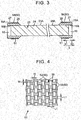
- FIG. 3 is a view schematically illustrating a step next to the step illustrated in FIG. 2 .
- FIG. 4 is a view illustrating fabric 51 of glass fibers 50.
- the glass fibers 50 (more specifically, a glass fiber prepreg 54 described later) are wound around the outer peripheral face 16A of each of the metal rings 16 as illustrated in FIG. 3 .
- the glass fibers 50 form the fabric 51 in the present embodiment.
- the fabric 51 is formed by weaving together bundles 52 of the glass fibers 50 extending linearly in a prescribed direction, and bundles 53 of the glass fibers 50 extending in a direction crossing (here, perpendicular to) the bundles 52 by plain weave.
- the bundles 52 extend in the up-down direction of the sheet on which FIG.
- a method of weaving the fabric 51 is not limited to the plain weave, and common weaving methods such as twill weave, satin weave, and multi-axial weave may be applied.
- the fabric 51 is impregnated with a resin 28, to thereby form the glass fiber prepreg 54 in the form of a sheet.
- a resin 28 a thermosetting resin such as an epoxy resin, a polyimide resin, a bismaleimide resin, and an unsaturated polyester resin may be used. Because the rack bar 8 is used in an engine room of the vehicle, a curing temperature of the resin 28 is desired to be equal to or higher than the upper-limit temperature (for example, 130°C or higher) expected in the engine room.
- FIG. 5 is a view schematically illustrating a step next to the step illustrated in FIG. 3 .
- a carbon fiber prepreg 26 is used as a prepreg sheet that is a material of the pipe 10 described above.
- the carbon fiber prepreg 26 is in the form of a sheet obtained, for example, by impregnating a large number of carbon fibers 25 arranged in a uni-direction with the resin 28.
- Various kinds of carbon fibers represented by "Torayca” (registered trademark) T300 or “Torayca” (registered trademark) T700 may be used for the carbon fiber prepreg 26.
- the carbon fibers 25 used for the carbon fiber prepreg 26 may be partially replaced with glass fibers or aramid fibers.
- the carbon fiber prepreg 26 is wound around the outer peripheral face 23A of the core member 23 once, or twice or more by, for example, a sheet winding method.
- the carbon fiber prepreg 26 extends over the mandrel 24, the metal rings 16 and the glass fiber prepregs 54.
- the carbon fiber prepreg 26 surrounds the core member 23 in close contact with the outer peripheral face 24A of the mandrel 24 and the glass fiber prepregs 54, the carbon fiber prepreg 26 has a generally cylindrical shape as a whole.
- the fabric 51 of the glass fibers 50 is interposed between the carbon fiber prepreg 26 and the outer peripheral face 16A of each of the metal rings 16, and is disposed on the outer peripheral face 16A, at a position radially inward of the carbon fiber prepreg 26 (i.e., the fabric 51 forms the innermost layer).
- the opposite end portions of the carbon fiber prepreg 26 in the wound state in the axial direction X have a diameter larger than that of a portion of the carbon fiber prepreg 26 other than the opposite end portions in the axial direction X, by an amount corresponding to the thickness of the metal ring 16 and the glass fiber prepreg 54.
- the inner diameter of the carbon fiber prepreg 26 in the portion other than the opposite end portions in the axial direction X of the carbon fiber prepreg 26 is substantially equal to the inner diameter of each of the metal rings 16.
- the opposite end portions of the carbon fiber prepreg 26 in the axial direction X may extend up to positions on the outer sides of the glass fiber prepregs 52 in the axial direction X.
- the carbon fiber prepreg 26 is in close contact with the outer peripheral faces 16A of the metal rings 16, at the opposite end portions in the axial direction X.
- the carbon fiber prepreg 26 and the glass fiber prepregs 54 wound around the outer peripheral face 23A of the core member 23 are cured by baking.
- the shape of the carbon fiber prepreg 26 is fixed in the generally cylindrical shape that is formed when the carbon fiber prepreg 26 is wound around the outer peripheral face 23A of the core member 23.
- each of the glass fiber prepregs 54 is fixed in the generally cylindrical shape having an inner peripheral face that conforms to the asperities 27 of the outer peripheral face 16A of each of the metal rings 16.
- the carbon fiber prepreg 26 is cooled at room temperature to be turned into the pipe 10. That is, the pipe 10 is formed by bake-curing the carbon fiber prepreg 26 wound around the outer peripheral face 23A.
- the pipe 10 is externally fitted (more specifically, externally fitted and fixed as described later) onto the outer peripheral faces 16A of the metal rings 16, at the end portions 10A, 10B.
- the carbon fiber prepreg 26 is wound around the outer peripheral face 23A of the core member 23 mainly in such a winding method that the direction in which the carbon fibers 25 extend is oblique to the axial direction X (so-called helical winding). Therefore, the carbon fibers 25 within the pipe 10 extend in a prescribed direction that is oblique to the axial direction X, so that the pipe 10 has a high strength with respect to the axial direction X. Subsequently, only the mandrel 24 in the core member 23 is pulled out of the pipe 10. At this time, the mandrel 24 may be shrunk by cooling so as to be smoothly pulled out. In this case, a force required to pull the mandrel 24 out of the pipe 10 is reduced.
- each of the metal rings 16 remains internally fitted to a corresponding one of the end portion 10A and the end portion 10B of the pipe 10. It is also preferable that the metal rings 16 partially (for example, about 2 mm of end portions in the axial direction X) protrude to the outside of the end portion 10A and the end portion 10B of the pipe 10 in the axial direction X. For this reason, when each of the glass fiber prepregs 54 and the carbon fiber prepreg 26 is wound around the outer peripheral face 23A of the core member 23, a portion of each of the metal rings 16 may be exposed so as to protrude to the outside side of the completed pipe 10 in the axial direction X.
- FIG. 6 is a view schematically illustrating a step next to the step illustrated in FIG. 5 .
- a female threaded portion 19 is subsequently formed on the inner peripheral face 16B of each of the metal rings 16.
- the female threaded portion 19 is formed over an entire region of the inner peripheral face 16B.
- the pipe 10 and the first and second metal members 17, 18 are connected together by using a connection method such as screwing, helical insert fastening, and spline press-fitting. Therefore, in the case of the comparative example, it is necessary to perform screw machining or spline machining on the inner peripheral face 10C of the pipe 10.
- the carbon fiber prepreg 26 In order to prevent the carbon fibers 25 from being cut off in the comparative example, it is necessary to wind, around the core member 23, the carbon fiber prepreg 26 at least in an innermost layer (closest to the core member 23) by a winding method in which the carbon fibers 25 extend in a circumferential direction of the core member 23 (so-called hoop winding).
- the pipe 10 can be formed only by helical winding (or with a higher percentage of helical winding). That is, in the present embodiment, the pipe 10 can be formed only by one type of winding method. It is thus possible to correspondingly decrease the number of windings of the carbon fiber prepreg 26 (to the core member 23) and increase the strength in the axial direction X as compared to the comparative example. That is, cost decrease, weight reduction, and strength improvement of the pipe 10 can be achieved by using the metal rings 16. A weight of the rack bar 8 is reduced by 45% by the weight reduction.
- FIG. 7 is a view schematically illustrating a step next to the step illustrated in FIG. 6 .
- a male threaded portion 20 is provided on an outer peripheral face of the small-diameter portion 21 of the first metal member 17.
- the female threaded portion 19 of the metal ring 16 on the left side X1 is screwed to the male threaded portion 20 of the first metal member 17.
- the first metal member 17 is screwed with the inner peripheral face 16B of the metal ring 16, and is fastened to the end portion 10A of the pipe 10 via the metal ring 16.
- a male threaded portion 20 is also provided on an outer peripheral face of the small-diameter portion 21 of the second metal member 18.
- the female threaded portion 19 of the metal ring 16 on the right side X2 is screwed to the male threaded portion 20 of the second metal member 18.
- the second metal member 18 is screwed with the inner peripheral face 16B of the metal ring 16, and is fastened to the end portion 10B of the pipe 10 via the metal ring 16.
- the pipe 10 is thereby fastened to the first metal member 17 and the second metal member 18 at the both end portions 10A, 10B in the axial direction X, so that the manufacture of the bar member 22 is completed.
- each of the metal rings 16 protrudes to the outer side in the axial direction X from the pipe 10 as described above. Therefore, when the pipe 10 is to be bent against the first metal member 17 and the second metal member 18, the first metal member 17 and the second metal member 18 come into contact with the metal rings 16, not the pipe 10. It is thus possible to prevent each of the end portions 10A, 10B of the pipe 10 from coming into contact with the corresponding one of the first metal member 17 and the second metal member 18. Accordingly, it is possible to prevent the pipe 10 from being damaged by coming into contact with the first metal member 17 and the second metal member 18.
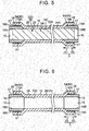
- FIG. 8 is an enlarged view of a portion surrounded by a dashed line in FIG. 7 .
- the resin 28 oozing out from the carbon fiber prepreg 26 and the glass fiber prepreg 54 is interposed between the inner peripheral face 10C of the pipe 10 and the outer peripheral face 16A of the metal ring 16 in the completed bar member 22.
- the resin 28 enters respective concave portions 29 of the asperities 27 formed on the outer peripheral face 16A, and is cured therein in the step of winding the carbon fiber prepreg 26 around the core member 23, and the subsequent bake-curing step described above (see FIG. 5 ).
- first and second metal members 17, 18 and the metal rings 16 are screwed together.
- the pipe 10 (strictly, the end portions 10A, 10B) and each of the first metal member 17 and the second metal member 18 can be fastened together without applying an unnecessary force to the metal rings 16. That is, the outer peripheral faces 16A of the metal rings 16 do not bite into the pipe 10, and the carbon fibers 25 within the pipe 10 are thus not cut off unlike in the case of press-fitting. Therefore, the strength in the connection portion between the pipe 10 and the first and second metal members 17, 18 is not lowered due to the cutting-off of the carbon fibers 25.
- the carbon fibers 25 within the pipe 10 are not cut off as described above.
- the carbon fiber prepreg 26 is directly wound around the outer peripheral face 23A of the core member 23 by the sheet winding method described above, it is difficult to place the carbon fiber prepreg 26 along the asperities 27 of the metal rings 16. Therefore, strength in a connection portion between the metal rings 16 and the pipe 10 is weakest in the bar member 22. Therefore, the pipe 10 could be detached from the metal rings 16 depending on a stress applied to the bar member 22.
- the glass fibers 50 are fixed in a state in which the glass fibers 50 enter the concave portions 29 of the outer peripheral face 16A of each of the metal rings 16, and are caught on the convex portions 35 of the outer peripheral face 16A of each of the metal rings 16 after the bake-curing.
- the pipe 10 is more hardly detached from the metal rings 16 with the glass fibers 50 therebetween.
- the end portions 10A, 10B of the pipe 10 are externally fitted and fixed to (prevented from being detached from) the outer peripheral faces 16A of the corresponding metal rings 16 in a state in which the carbon fibers 25 within the pipe 10 are not cut off.
- the metal rings 16 in the state are positioned so as not to be displaced in the axial direction X or a circumferential direction of the pipe 10 with respect to the end portions 10A, 10B of the pipe 10.
- the glass fibers 50 of the present embodiment form the fabric 51.
- the fabric 51 is arranged such that the bundles 52 of the glass fibers 50 (see FIG. 4 ) are aligned with a circumferential direction C of the outer peripheral face 16A of the metal ring 16.
- a thickness L1 of each of the bundles 52 and 53 in the axial direction X or the circumferential direction C (see FIG. 4 ) is smaller than a pitch P between the convex portions 35 of the asperities 27 (also a pitch between the concave portions 29).
- a thickness L2 of each of the bundles 52 and 53 in a radial direction of the outer peripheral face 16A is smaller than a height H of the convex portions 35 (a depth of the concave portions 29). Therefore, the bundles 52 and 53 can enter the concave portions 29.
- the convex portions 35 of the outer peripheral face 16A of each of the metal rings 16 enter interstices 58 of the fabric 51, so that the glass fibers 50 in the fabric 51 enter the concave portions 29 of the outer peripheral face 16A of each of the metal rings 16, and are fixed to the outer peripheral face 16A of each of the metal rings 16 by the bake-curing. Accordingly, the metal rings 16 and the pipe 10 are more rigidly fixed together, and the pipe 10 becomes more hardly detached from the metal rings 16.
- a width W of each of the interstices 58 in the circumferential direction C and the axial direction X is desired to be larger than the pitch P between the convex portions 35.
- FIG. 9 is a view obtained by applying the first modification to FIG. 8 .
- the step of winding the glass fibers 50 around the outer peripheral face 16A of the metal ring 16 in the first modification includes a step of winding a non-woven fabric 55 of the glass fibers 50 around the outer peripheral face 16A.
- a non-woven fabric 55 for example, a chopped strand mat is preferably used.
- the glass fibers 50 in the first modification have a rod-like shape of about 0.5 to 20 mm, and are dispersed in the non-woven fabric 55.
- the non-woven fabric 55 also includes the glass fibers 50 having a different shape in section and glass flakes 57 having a planar shape in addition to the rod-like glass fibers 50.
- the non-woven fabric 55 is interposed between the outer peripheral face 16A of each of the metal rings 16 and the carbon fiber prepreg 26.
- the carbon fiber prepreg 26 is cured by baking, so that the pipe 10 is formed. Accordingly, the non-woven fabric 55 is fixed between the carbon fiber prepreg 26 and each of the metal rings 16 by the resin 28 oozing out from the carbon fiber prepreg 26.
- the glass fibers 50 and the glass flakes 57 in the non-woven fabric 55 are fixed entering the concave portions 29 of the outer peripheral face 16A of each of the metal rings 16 in a state in which the glass fibers 50 and the glass flakes 57 are oriented in various directions.
- the glass fibers 50 and the glass flakes 57 are caught on the convex portions 35 of the outer peripheral face 16A of each of the metal rings 16 from various directions to effectively act as resistance.
- the pipe 10 thereby becomes more hardly detached from the metal rings 16.
- the step of providing, on the inner peripheral faces 16B of the metal rings 16, the female threaded portions 19 that are to be screwed to the male threaded portions 20 provided on the first metal member 17 and the second metal member 18 is performed after the mandrel 24 is pulled out of the pipe 10.
- the step may be performed before the metal rings 16 are externally fitted to the mandrel 24.
- the step of winding the glass fibers 50 around the outer peripheral face 16A of each of the metal rings 16 includes a step of winding the fabric 51 that is not impregnated with the resin 28 around the outer peripheral face 16A.
- the fabric 51 is fixed to the outer peripheral face 16A by the resin 28 oozing out from the carbon fiber prepreg 26.
- the types of the thermosetting resins of the resin 28 with which the carbon fiber prepreg 26 is impregnated and the resin 28 with which the glass fiber prepreg 54 is impregnated may be different from each other.
- the bar member 22 of the aforementioned embodiment has a configuration in which the metal members (the first metal member 17 and the second metal member 18) are fastened to the both end portions (both of the end portions 10A, 10B) of the pipe 10, the bar member 22 may also have a configuration in which the metal member is fastened to only one of the both end portions.
- the bar member 22 of the aforementioned embodiment is the rack bar 8
- a bar member other than the rack bar 8 e.g., various shafts, rods, pipe-like components
Landscapes
- Engineering & Computer Science (AREA)
- General Engineering & Computer Science (AREA)
- Mechanical Engineering (AREA)
- Chemical & Material Sciences (AREA)
- Composite Materials (AREA)
- Ocean & Marine Engineering (AREA)
- Electromagnetism (AREA)
- Thermal Sciences (AREA)
- Physics & Mathematics (AREA)
- Combustion & Propulsion (AREA)
- Transportation (AREA)
- Moulding By Coating Moulds (AREA)
- Transmission Devices (AREA)
- Shafts, Cranks, Connecting Bars, And Related Bearings (AREA)
Claims (7)
- Verfahren zur Herstellung eines Stangenelementes (22), das ein Rohr (10), das aus einem karbonfaserverstärkten Harz hergestellt ist, und ein Metallelement (17, 18) aufweist, welches in einer Axialrichtung des Rohrs (10) an einem Endabschnitt (10A, 10B) des Rohrs (10) befestigt ist, wobei das Verfahren aufweist:einen Schritt zum Ausbilden eines Kernelementes (23), der eine Spindel (24), die aus Metall hergestellt ist und sich in die Axialrichtung erstreckt, und einen Metallring (16) aufweist, der eine Außenumfangsfläche (16A) hat, die einer Oberflächenaufrauhung unterworfen worden ist, indem der Metallring (16) von außen auf die Spindel (24) gepasst wird;einen Schritt zum Wickeln von Glasfasern (50) um die Außenumfangsfläche (16A) des Metallrings (16);einen Schritt zum Einfügen der Glasfasern (50) zwischen ein Prepreg-Blatt, das durch das Imprägnieren von Karbonfasern (25) mit einem Harz (28) erhalten wird, und die Außenumfangsfläche (16A) des Metallrings (16), indem das Prepreg-Blatt (26) um eine Außenumfangsfläche (23A) des Kernelementes (23) gewickelt wird, wobei das Karbonfaser-Prepreg (26) in engem Kontakt mit einer Außenumfangsfläche (24A) der Spule (24) und mit den Glasfasern (50) steht;einen Schritt zum Ausbilden des Rohrs (10), bei dem der Endabschnitt durch Ausbacken und Aushärten des Prepreg-Blatts (26), das um die Außenumfangsfläche (23A) des Kernelementes (23) gewickelt ist, von außen an die Außenumfangsfläche (16A) des Metallrings (16) gepasst und daran fixiert wird;einen Schritt zum Ziehen von allein der Spule (24) aus dem Rohr (10) in das Kernelement (23); undeinen Schritt zum Zusammenschrauben von Metallelement (17, 18) und einer Innenumfangsfläche (16B) des Metallrings (16).
- Verfahren zum Herstellen eines Stangenelementes (22) gemäß Anspruch 1, wobei der Schritt zum Wickeln der Glasfasern (50) um die Außenumfangsfläche (16A) des Metallrings (16) einen Schritt zum Wickeln von einem Gewebe (51) der Glasfasern (50) um die Außenumfangsfläche (16A) des Metallrings (16) aufweist.
- Verfahren zum Herstellen eines Stangenelementes (22) gemäß Anspruch 1, wobei der Schritt zum Wickeln der Glasfasern (50) um die Außenumfangsfläche (16A) des Metallrings (16) einen Schritt zum Wickeln von einem Vliesstoff (55) von Glasfasern (50) um die Außenumfangsfläche (16A) des Metallrings (16) aufweist.
- Verfahren zum Herstellen eines Stangenelementes (22) gemäß einem der Ansprüche 1 bis 3, weiterhin mit einem Schritt zum Freihalten eines Abschnittes des Metallrings (16), sodass der Abschnitt von dem fertiggestellten Rohr (10) aus in Axialrichtung zu einer Außenseite hervorragt, wenn sowohl die Glasfasern (50) als auch das Prepreg-Blatt (26) um die Außenumfangsfläche (23A) des Kernelementes (23) gewickelt werden.
- Verfahren zum Herstellen eines Stangenelementes (22) gemäß einem der Ansprüche 1 bis 4, weiterhin mit einem Schritt zum Ausbilden eines Innengewindeabschnittes (19) an der Innenumfangsfläche (16B) des Metallrings (16), wobei der Innengewindeabschnitt (19) mit einem Außengewindeabschnitt (20), der an dem Metallelement (17, 18) vorgesehen ist, verschraubt werden soll.
- Stangenelement (22), das durch das Herstellungsverfahren nach einem der Ansprüche 1 bis 5 hergestellt ist.
- Stangenelement (22) gemäß Anspruch 6, wobei das Stangenelement (22) eine Zahnstange (8) bildet, welche in einer Zahnstangen-Lenkvorrichtung (1) enthalten ist.
Applications Claiming Priority (1)
| Application Number | Priority Date | Filing Date | Title |
|---|---|---|---|
| JP2014019475A JP6304804B2 (ja) | 2014-02-04 | 2014-02-04 | バー状部品の製造方法およびバー状部品 |
Publications (2)
| Publication Number | Publication Date |
|---|---|
| EP2902165A1 EP2902165A1 (de) | 2015-08-05 |
| EP2902165B1 true EP2902165B1 (de) | 2019-01-16 |
Family
ID=52464202
Family Applications (1)
| Application Number | Title | Priority Date | Filing Date |
|---|---|---|---|
| EP15153731.3A Not-in-force EP2902165B1 (de) | 2014-02-04 | 2015-02-04 | Verfahren zur Herstellung eines Stangenelements und Stangenelement |
Country Status (4)
| Country | Link |
|---|---|
| US (1) | US9695925B2 (de) |
| EP (1) | EP2902165B1 (de) |
| JP (1) | JP6304804B2 (de) |
| CN (1) | CN104816753B (de) |
Families Citing this family (9)
| Publication number | Priority date | Publication date | Assignee | Title |
|---|---|---|---|---|
| JP2017082811A (ja) * | 2015-10-22 | 2017-05-18 | 高周波熱錬株式会社 | ラックバー及びラックバーの製造方法 |
| CN105328920B (zh) * | 2015-12-07 | 2018-01-23 | 江苏神马电力股份有限公司 | 绝缘拉杆的浸渍成型装置及方法 |
| WO2020099607A1 (fr) * | 2018-11-15 | 2020-05-22 | Bd Invent S.A. | Procede de fabrication de bielles en composite avec inserts visses |
| JP2020142408A (ja) * | 2019-03-05 | 2020-09-10 | 藤倉コンポジット株式会社 | Frp複合成形品及びその製造方法 |
| EP3859175B1 (de) * | 2020-01-29 | 2025-09-17 | Crompton Technology Group Limited | Endanschlüsse aus verbundwerkstoff |
| CN111353483B (zh) * | 2020-05-25 | 2020-10-16 | 深圳大学 | 一种杆状设施结构特征提取方法及相关设备 |
| CN111559089B (zh) * | 2020-06-09 | 2024-07-26 | 衡水市瑞丰复合材料有限公司 | 玻璃纤维增强塑料管及制备方法 |
| CN112253606A (zh) * | 2020-10-15 | 2021-01-22 | 东风越野车有限公司 | 轻量化碳纤维传动轴及其连接结构与整车 |
| US20250367899A1 (en) * | 2024-05-29 | 2025-12-04 | AvtechTyee, Inc. | Co-cured multi-material composite tubes and composite tube assemblies incorporating such composite tubes |
Family Cites Families (17)
| Publication number | Priority date | Publication date | Assignee | Title |
|---|---|---|---|---|
| JPS539378U (de) * | 1976-07-09 | 1978-01-26 | ||
| US4171626A (en) * | 1978-03-27 | 1979-10-23 | Celanese Corporation | Carbon fiber reinforced composite drive shaft |
| US4238539A (en) * | 1979-05-29 | 1980-12-09 | Celanese Corporation | Fiber reinforced composite shaft with metallic connector sleeves mounted by a knurl interlock |
| US4380443A (en) | 1979-11-17 | 1983-04-19 | Felten & Guilleaume Carlswerk Aktiengesellschaft | Fiber-reinforced drive shaft |
| US4569710A (en) * | 1980-12-30 | 1986-02-11 | Societe Anonyme Diamant Boart | Process for manufacturing the inner tube element for a double tube coring apparatus |
| GB2154299B (en) * | 1984-02-15 | 1986-11-05 | Trw Cam Gears Ltd | A rack bar housing assembly |
| JPS6426430A (en) * | 1987-07-23 | 1989-01-27 | Sumitomo Metal Ind | Frp pipe with threaded joint |
| JPH0745198B2 (ja) * | 1987-10-15 | 1995-05-17 | 東燃株式会社 | 繊維強化複合樹脂管及びその製造法 |
| JP2805327B2 (ja) * | 1988-06-24 | 1998-09-30 | 東燃株式会社 | 繊維強化複合樹脂製棒状成形体及びその製造方法 |
| US5236018A (en) * | 1988-06-24 | 1993-08-17 | Tao Nenryo Kogyo Kabushiki Kaisha | Boring casing for boring machines |
| JPH0592488A (ja) * | 1991-04-30 | 1993-04-16 | Sumitomo Chem Co Ltd | 繊維強化樹脂製駆動力伝達用シヤフト、その製造方法及び繊維強化樹脂製パイプの接合方法 |
| TW206182B (de) * | 1991-04-30 | 1993-05-21 | Sumitomo Chemical Co | |
| JPH05193097A (ja) | 1992-01-21 | 1993-08-03 | Nitto Denko Corp | グラビア用印刷ロール |
| JPH0791433A (ja) | 1993-09-20 | 1995-04-04 | Toray Ind Inc | プロペラシャフトおよびその製造方法 |
| US20080127762A1 (en) | 2004-12-20 | 2008-06-05 | Bishop Innovation Limited | Composite Steering Rack |
| JP2010095159A (ja) * | 2008-10-16 | 2010-04-30 | Nsk Ltd | 車両ステアリング用伸縮軸の製造方法 |
| JP2012153314A (ja) | 2011-01-28 | 2012-08-16 | Nsk Ltd | ラックアンドピニオン式ステアリング装置用ラック |
-
2014
- 2014-02-04 JP JP2014019475A patent/JP6304804B2/ja not_active Expired - Fee Related
-
2015
- 2015-02-03 CN CN201510056371.6A patent/CN104816753B/zh not_active Expired - Fee Related
- 2015-02-03 US US14/612,687 patent/US9695925B2/en not_active Expired - Fee Related
- 2015-02-04 EP EP15153731.3A patent/EP2902165B1/de not_active Not-in-force
Non-Patent Citations (1)
| Title |
|---|
| None * |
Also Published As
| Publication number | Publication date |
|---|---|
| JP2015145121A (ja) | 2015-08-13 |
| JP6304804B2 (ja) | 2018-04-04 |
| US20150219201A1 (en) | 2015-08-06 |
| CN104816753A (zh) | 2015-08-05 |
| CN104816753B (zh) | 2019-02-12 |
| EP2902165A1 (de) | 2015-08-05 |
| US9695925B2 (en) | 2017-07-04 |
Similar Documents
| Publication | Publication Date | Title |
|---|---|---|
| EP2902165B1 (de) | Verfahren zur Herstellung eines Stangenelements und Stangenelement | |
| EP2474751B1 (de) | Aus fvk hergestellte antriebswelle | |
| EP3295047B1 (de) | Torsionsrohre oder -wellen aus faserverstärktem polymermatrixverbund | |
| EP3382221B1 (de) | Zusammengesetzte endanschlüsse | |
| TWI862676B (zh) | 產生應用在拉壓桿之正鎖定載重的方法及拉壓桿 | |
| US9956987B2 (en) | Manufacturing method of bar component and bar component | |
| BR102020019950A2 (pt) | eixo composto com um encaixe de extremidade, e, método de montagem de um encaixe de extremidade em um eixo composto. | |
| WO2016080178A1 (ja) | 動力伝達シャフト | |
| JP6222448B2 (ja) | バー状部品の製造方法 | |
| EP3769947B1 (de) | Hybride metall-/verbundstoffrohrkonstruktion zur übertragung von biege-, axial- und elastischer schubbeanspruchung | |
| JP2015131423A (ja) | バー状部品の製造方法 | |
| JP6288418B2 (ja) | ラックバーの製造方法 | |
| CN115023338A (zh) | 管体中间体和管体制造方法 | |
| US10184212B2 (en) | Coupling body using Z-pin | |
| US12429150B2 (en) | Tube body intermediate | |
| JP7231787B2 (ja) | 管体製造方法 | |
| JP2015139930A (ja) | バー状部品の製造方法およびバー状部品 | |
| RU2819679C1 (ru) | Способ создания приложения нагрузки с принудительной блокировкой для стержня растяжения-сжатия и соответствующий стержень | |
| WO2016125517A1 (ja) | 動力伝達シャフト |
Legal Events
| Date | Code | Title | Description |
|---|---|---|---|
| PUAI | Public reference made under article 153(3) epc to a published international application that has entered the european phase |
Free format text: ORIGINAL CODE: 0009012 |
|
| 17P | Request for examination filed |
Effective date: 20150204 |
|
| AK | Designated contracting states |
Kind code of ref document: A1 Designated state(s): AL AT BE BG CH CY CZ DE DK EE ES FI FR GB GR HR HU IE IS IT LI LT LU LV MC MK MT NL NO PL PT RO RS SE SI SK SM TR |
|
| AX | Request for extension of the european patent |
Extension state: BA ME |
|
| 17P | Request for examination filed |
Effective date: 20160111 |
|
| RBV | Designated contracting states (corrected) |
Designated state(s): AL AT BE BG CH CY CZ DE DK EE ES FI FR GB GR HR HU IE IS IT LI LT LU LV MC MK MT NL NO PL PT RO RS SE SI SK SM TR |
|
| GRAP | Despatch of communication of intention to grant a patent |
Free format text: ORIGINAL CODE: EPIDOSNIGR1 |
|
| STAA | Information on the status of an ep patent application or granted ep patent |
Free format text: STATUS: GRANT OF PATENT IS INTENDED |
|
| RIC1 | Information provided on ipc code assigned before grant |
Ipc: B29L 31/00 20060101ALN20180618BHEP Ipc: F16C 3/02 20060101ALI20180618BHEP Ipc: B29L 23/00 20060101ALN20180618BHEP Ipc: B29C 70/32 20060101ALI20180618BHEP Ipc: F16H 55/26 20060101ALI20180618BHEP Ipc: B29L 31/24 20060101ALN20180618BHEP Ipc: B29C 70/86 20060101ALI20180618BHEP Ipc: F16H 55/06 20060101ALI20180618BHEP Ipc: B29C 37/00 20060101AFI20180618BHEP |
|
| RIC1 | Information provided on ipc code assigned before grant |
Ipc: B29L 23/00 20060101ALN20180705BHEP Ipc: B29L 31/24 20060101ALN20180705BHEP Ipc: B29C 70/32 20060101ALI20180705BHEP Ipc: F16H 55/26 20060101ALI20180705BHEP Ipc: B29C 70/86 20060101ALI20180705BHEP Ipc: F16C 3/02 20060101ALI20180705BHEP Ipc: F16H 55/06 20060101ALI20180705BHEP Ipc: B29C 37/00 20060101AFI20180705BHEP Ipc: B29L 31/00 20060101ALN20180705BHEP |
|
| INTG | Intention to grant announced |
Effective date: 20180723 |
|
| GRAS | Grant fee paid |
Free format text: ORIGINAL CODE: EPIDOSNIGR3 |
|
| GRAA | (expected) grant |
Free format text: ORIGINAL CODE: 0009210 |
|
| STAA | Information on the status of an ep patent application or granted ep patent |
Free format text: STATUS: THE PATENT HAS BEEN GRANTED |
|
| RIN1 | Information on inventor provided before grant (corrected) |
Inventor name: TOYODOME, SHUJI Inventor name: KUNISHIMA, TAKESHI |
|
| AK | Designated contracting states |
Kind code of ref document: B1 Designated state(s): AL AT BE BG CH CY CZ DE DK EE ES FI FR GB GR HR HU IE IS IT LI LT LU LV MC MK MT NL NO PL PT RO RS SE SI SK SM TR |
|
| RAP1 | Party data changed (applicant data changed or rights of an application transferred) |
Owner name: TIP COMPOSITE Owner name: JTEKT CORPORATION |
|
| REG | Reference to a national code |
Ref country code: GB Ref legal event code: FG4D |
|
| REG | Reference to a national code |
Ref country code: CH Ref legal event code: EP |
|
| REG | Reference to a national code |
Ref country code: IE Ref legal event code: FG4D |
|
| REG | Reference to a national code |
Ref country code: AT Ref legal event code: REF Ref document number: 1089378 Country of ref document: AT Kind code of ref document: T Effective date: 20190215 |
|
| REG | Reference to a national code |
Ref country code: DE Ref legal event code: R096 Ref document number: 602015023459 Country of ref document: DE |
|
| REG | Reference to a national code |
Ref country code: NL Ref legal event code: MP Effective date: 20190116 |
|
| REG | Reference to a national code |
Ref country code: LT Ref legal event code: MG4D |
|
| PG25 | Lapsed in a contracting state [announced via postgrant information from national office to epo] |
Ref country code: NL Free format text: LAPSE BECAUSE OF FAILURE TO SUBMIT A TRANSLATION OF THE DESCRIPTION OR TO PAY THE FEE WITHIN THE PRESCRIBED TIME-LIMIT Effective date: 20190116 |
|
| REG | Reference to a national code |
Ref country code: AT Ref legal event code: MK05 Ref document number: 1089378 Country of ref document: AT Kind code of ref document: T Effective date: 20190116 |
|
| PG25 | Lapsed in a contracting state [announced via postgrant information from national office to epo] |
Ref country code: SE Free format text: LAPSE BECAUSE OF FAILURE TO SUBMIT A TRANSLATION OF THE DESCRIPTION OR TO PAY THE FEE WITHIN THE PRESCRIBED TIME-LIMIT Effective date: 20190116 Ref country code: ES Free format text: LAPSE BECAUSE OF FAILURE TO SUBMIT A TRANSLATION OF THE DESCRIPTION OR TO PAY THE FEE WITHIN THE PRESCRIBED TIME-LIMIT Effective date: 20190116 Ref country code: LT Free format text: LAPSE BECAUSE OF FAILURE TO SUBMIT A TRANSLATION OF THE DESCRIPTION OR TO PAY THE FEE WITHIN THE PRESCRIBED TIME-LIMIT Effective date: 20190116 Ref country code: PT Free format text: LAPSE BECAUSE OF FAILURE TO SUBMIT A TRANSLATION OF THE DESCRIPTION OR TO PAY THE FEE WITHIN THE PRESCRIBED TIME-LIMIT Effective date: 20190516 Ref country code: PL Free format text: LAPSE BECAUSE OF FAILURE TO SUBMIT A TRANSLATION OF THE DESCRIPTION OR TO PAY THE FEE WITHIN THE PRESCRIBED TIME-LIMIT Effective date: 20190116 Ref country code: NO Free format text: LAPSE BECAUSE OF FAILURE TO SUBMIT A TRANSLATION OF THE DESCRIPTION OR TO PAY THE FEE WITHIN THE PRESCRIBED TIME-LIMIT Effective date: 20190416 Ref country code: FI Free format text: LAPSE BECAUSE OF FAILURE TO SUBMIT A TRANSLATION OF THE DESCRIPTION OR TO PAY THE FEE WITHIN THE PRESCRIBED TIME-LIMIT Effective date: 20190116 |
|
| PG25 | Lapsed in a contracting state [announced via postgrant information from national office to epo] |
Ref country code: IS Free format text: LAPSE BECAUSE OF FAILURE TO SUBMIT A TRANSLATION OF THE DESCRIPTION OR TO PAY THE FEE WITHIN THE PRESCRIBED TIME-LIMIT Effective date: 20190516 Ref country code: BG Free format text: LAPSE BECAUSE OF FAILURE TO SUBMIT A TRANSLATION OF THE DESCRIPTION OR TO PAY THE FEE WITHIN THE PRESCRIBED TIME-LIMIT Effective date: 20190416 Ref country code: HR Free format text: LAPSE BECAUSE OF FAILURE TO SUBMIT A TRANSLATION OF THE DESCRIPTION OR TO PAY THE FEE WITHIN THE PRESCRIBED TIME-LIMIT Effective date: 20190116 Ref country code: RS Free format text: LAPSE BECAUSE OF FAILURE TO SUBMIT A TRANSLATION OF THE DESCRIPTION OR TO PAY THE FEE WITHIN THE PRESCRIBED TIME-LIMIT Effective date: 20190116 Ref country code: GR Free format text: LAPSE BECAUSE OF FAILURE TO SUBMIT A TRANSLATION OF THE DESCRIPTION OR TO PAY THE FEE WITHIN THE PRESCRIBED TIME-LIMIT Effective date: 20190417 Ref country code: LV Free format text: LAPSE BECAUSE OF FAILURE TO SUBMIT A TRANSLATION OF THE DESCRIPTION OR TO PAY THE FEE WITHIN THE PRESCRIBED TIME-LIMIT Effective date: 20190116 |
|
| REG | Reference to a national code |
Ref country code: CH Ref legal event code: PL |
|
| REG | Reference to a national code |
Ref country code: DE Ref legal event code: R097 Ref document number: 602015023459 Country of ref document: DE |
|
| PG25 | Lapsed in a contracting state [announced via postgrant information from national office to epo] |
Ref country code: LU Free format text: LAPSE BECAUSE OF NON-PAYMENT OF DUE FEES Effective date: 20190204 Ref country code: AL Free format text: LAPSE BECAUSE OF FAILURE TO SUBMIT A TRANSLATION OF THE DESCRIPTION OR TO PAY THE FEE WITHIN THE PRESCRIBED TIME-LIMIT Effective date: 20190116 Ref country code: MC Free format text: LAPSE BECAUSE OF FAILURE TO SUBMIT A TRANSLATION OF THE DESCRIPTION OR TO PAY THE FEE WITHIN THE PRESCRIBED TIME-LIMIT Effective date: 20190116 Ref country code: SK Free format text: LAPSE BECAUSE OF FAILURE TO SUBMIT A TRANSLATION OF THE DESCRIPTION OR TO PAY THE FEE WITHIN THE PRESCRIBED TIME-LIMIT Effective date: 20190116 Ref country code: IT Free format text: LAPSE BECAUSE OF FAILURE TO SUBMIT A TRANSLATION OF THE DESCRIPTION OR TO PAY THE FEE WITHIN THE PRESCRIBED TIME-LIMIT Effective date: 20190116 Ref country code: DK Free format text: LAPSE BECAUSE OF FAILURE TO SUBMIT A TRANSLATION OF THE DESCRIPTION OR TO PAY THE FEE WITHIN THE PRESCRIBED TIME-LIMIT Effective date: 20190116 Ref country code: EE Free format text: LAPSE BECAUSE OF FAILURE TO SUBMIT A TRANSLATION OF THE DESCRIPTION OR TO PAY THE FEE WITHIN THE PRESCRIBED TIME-LIMIT Effective date: 20190116 Ref country code: AT Free format text: LAPSE BECAUSE OF FAILURE TO SUBMIT A TRANSLATION OF THE DESCRIPTION OR TO PAY THE FEE WITHIN THE PRESCRIBED TIME-LIMIT Effective date: 20190116 Ref country code: RO Free format text: LAPSE BECAUSE OF FAILURE TO SUBMIT A TRANSLATION OF THE DESCRIPTION OR TO PAY THE FEE WITHIN THE PRESCRIBED TIME-LIMIT Effective date: 20190116 Ref country code: CZ Free format text: LAPSE BECAUSE OF FAILURE TO SUBMIT A TRANSLATION OF THE DESCRIPTION OR TO PAY THE FEE WITHIN THE PRESCRIBED TIME-LIMIT Effective date: 20190116 |
|
| REG | Reference to a national code |
Ref country code: BE Ref legal event code: MM Effective date: 20190228 |
|
| PLBE | No opposition filed within time limit |
Free format text: ORIGINAL CODE: 0009261 |
|
| STAA | Information on the status of an ep patent application or granted ep patent |
Free format text: STATUS: NO OPPOSITION FILED WITHIN TIME LIMIT |
|
| REG | Reference to a national code |
Ref country code: IE Ref legal event code: MM4A |
|
| PG25 | Lapsed in a contracting state [announced via postgrant information from national office to epo] |
Ref country code: SM Free format text: LAPSE BECAUSE OF FAILURE TO SUBMIT A TRANSLATION OF THE DESCRIPTION OR TO PAY THE FEE WITHIN THE PRESCRIBED TIME-LIMIT Effective date: 20190116 |
|
| 26N | No opposition filed |
Effective date: 20191017 |
|
| GBPC | Gb: european patent ceased through non-payment of renewal fee |
Effective date: 20190416 |
|
| PG25 | Lapsed in a contracting state [announced via postgrant information from national office to epo] |
Ref country code: LI Free format text: LAPSE BECAUSE OF NON-PAYMENT OF DUE FEES Effective date: 20190228 Ref country code: CH Free format text: LAPSE BECAUSE OF NON-PAYMENT OF DUE FEES Effective date: 20190228 |
|
| PG25 | Lapsed in a contracting state [announced via postgrant information from national office to epo] |
Ref country code: GB Free format text: LAPSE BECAUSE OF NON-PAYMENT OF DUE FEES Effective date: 20190416 Ref country code: IE Free format text: LAPSE BECAUSE OF NON-PAYMENT OF DUE FEES Effective date: 20190204 |
|
| PG25 | Lapsed in a contracting state [announced via postgrant information from national office to epo] |
Ref country code: BE Free format text: LAPSE BECAUSE OF NON-PAYMENT OF DUE FEES Effective date: 20190228 Ref country code: SI Free format text: LAPSE BECAUSE OF FAILURE TO SUBMIT A TRANSLATION OF THE DESCRIPTION OR TO PAY THE FEE WITHIN THE PRESCRIBED TIME-LIMIT Effective date: 20190116 |
|
| PG25 | Lapsed in a contracting state [announced via postgrant information from national office to epo] |
Ref country code: TR Free format text: LAPSE BECAUSE OF FAILURE TO SUBMIT A TRANSLATION OF THE DESCRIPTION OR TO PAY THE FEE WITHIN THE PRESCRIBED TIME-LIMIT Effective date: 20190116 |
|
| PGFP | Annual fee paid to national office [announced via postgrant information from national office to epo] |
Ref country code: DE Payment date: 20200121 Year of fee payment: 6 |
|
| PG25 | Lapsed in a contracting state [announced via postgrant information from national office to epo] |
Ref country code: MT Free format text: LAPSE BECAUSE OF NON-PAYMENT OF DUE FEES Effective date: 20190204 |
|
| PGFP | Annual fee paid to national office [announced via postgrant information from national office to epo] |
Ref country code: FR Payment date: 20200113 Year of fee payment: 6 |
|
| PG25 | Lapsed in a contracting state [announced via postgrant information from national office to epo] |
Ref country code: CY Free format text: LAPSE BECAUSE OF FAILURE TO SUBMIT A TRANSLATION OF THE DESCRIPTION OR TO PAY THE FEE WITHIN THE PRESCRIBED TIME-LIMIT Effective date: 20190116 |
|
| PG25 | Lapsed in a contracting state [announced via postgrant information from national office to epo] |
Ref country code: HU Free format text: LAPSE BECAUSE OF FAILURE TO SUBMIT A TRANSLATION OF THE DESCRIPTION OR TO PAY THE FEE WITHIN THE PRESCRIBED TIME-LIMIT; INVALID AB INITIO Effective date: 20150204 |
|
| REG | Reference to a national code |
Ref country code: DE Ref legal event code: R119 Ref document number: 602015023459 Country of ref document: DE |
|
| PG25 | Lapsed in a contracting state [announced via postgrant information from national office to epo] |
Ref country code: DE Free format text: LAPSE BECAUSE OF NON-PAYMENT OF DUE FEES Effective date: 20210901 Ref country code: FR Free format text: LAPSE BECAUSE OF NON-PAYMENT OF DUE FEES Effective date: 20210228 |
|
| PG25 | Lapsed in a contracting state [announced via postgrant information from national office to epo] |
Ref country code: MK Free format text: LAPSE BECAUSE OF FAILURE TO SUBMIT A TRANSLATION OF THE DESCRIPTION OR TO PAY THE FEE WITHIN THE PRESCRIBED TIME-LIMIT Effective date: 20190116 |