EP2902247A2 - Dispositif d'entraînement pour véhicule électrique - Google Patents
Dispositif d'entraînement pour véhicule électrique Download PDFInfo
- Publication number
- EP2902247A2 EP2902247A2 EP14200191.6A EP14200191A EP2902247A2 EP 2902247 A2 EP2902247 A2 EP 2902247A2 EP 14200191 A EP14200191 A EP 14200191A EP 2902247 A2 EP2902247 A2 EP 2902247A2
- Authority
- EP
- European Patent Office
- Prior art keywords
- torque
- balancing
- parking lock
- electric motor
- balancing torque
- Prior art date
- Legal status (The legal status is an assumption and is not a legal conclusion. Google has not performed a legal analysis and makes no representation as to the accuracy of the status listed.)
- Granted
Links
Images


Classifications
-
- B—PERFORMING OPERATIONS; TRANSPORTING
- B60—VEHICLES IN GENERAL
- B60L—PROPULSION OF ELECTRICALLY-PROPELLED VEHICLES; SUPPLYING ELECTRIC POWER FOR AUXILIARY EQUIPMENT OF ELECTRICALLY-PROPELLED VEHICLES; ELECTRODYNAMIC BRAKE SYSTEMS FOR VEHICLES IN GENERAL; MAGNETIC SUSPENSION OR LEVITATION FOR VEHICLES; MONITORING OPERATING VARIABLES OF ELECTRICALLY-PROPELLED VEHICLES; ELECTRIC SAFETY DEVICES FOR ELECTRICALLY-PROPELLED VEHICLES
- B60L15/00—Methods, circuits, or devices for controlling the traction-motor speed of electrically-propelled vehicles
- B60L15/20—Methods, circuits, or devices for controlling the traction-motor speed of electrically-propelled vehicles for control of the vehicle or its driving motor to achieve a desired performance, e.g. speed, torque, programmed variation of speed
- B60L15/2072—Methods, circuits, or devices for controlling the traction-motor speed of electrically-propelled vehicles for control of the vehicle or its driving motor to achieve a desired performance, e.g. speed, torque, programmed variation of speed for drive off
-
- B—PERFORMING OPERATIONS; TRANSPORTING
- B60—VEHICLES IN GENERAL
- B60L—PROPULSION OF ELECTRICALLY-PROPELLED VEHICLES; SUPPLYING ELECTRIC POWER FOR AUXILIARY EQUIPMENT OF ELECTRICALLY-PROPELLED VEHICLES; ELECTRODYNAMIC BRAKE SYSTEMS FOR VEHICLES IN GENERAL; MAGNETIC SUSPENSION OR LEVITATION FOR VEHICLES; MONITORING OPERATING VARIABLES OF ELECTRICALLY-PROPELLED VEHICLES; ELECTRIC SAFETY DEVICES FOR ELECTRICALLY-PROPELLED VEHICLES
- B60L15/00—Methods, circuits, or devices for controlling the traction-motor speed of electrically-propelled vehicles
- B60L15/20—Methods, circuits, or devices for controlling the traction-motor speed of electrically-propelled vehicles for control of the vehicle or its driving motor to achieve a desired performance, e.g. speed, torque, programmed variation of speed
- B60L15/2009—Methods, circuits, or devices for controlling the traction-motor speed of electrically-propelled vehicles for control of the vehicle or its driving motor to achieve a desired performance, e.g. speed, torque, programmed variation of speed for braking
- B60L15/2018—Methods, circuits, or devices for controlling the traction-motor speed of electrically-propelled vehicles for control of the vehicle or its driving motor to achieve a desired performance, e.g. speed, torque, programmed variation of speed for braking for braking on a slope
-
- B—PERFORMING OPERATIONS; TRANSPORTING
- B60—VEHICLES IN GENERAL
- B60L—PROPULSION OF ELECTRICALLY-PROPELLED VEHICLES; SUPPLYING ELECTRIC POWER FOR AUXILIARY EQUIPMENT OF ELECTRICALLY-PROPELLED VEHICLES; ELECTRODYNAMIC BRAKE SYSTEMS FOR VEHICLES IN GENERAL; MAGNETIC SUSPENSION OR LEVITATION FOR VEHICLES; MONITORING OPERATING VARIABLES OF ELECTRICALLY-PROPELLED VEHICLES; ELECTRIC SAFETY DEVICES FOR ELECTRICALLY-PROPELLED VEHICLES
- B60L15/00—Methods, circuits, or devices for controlling the traction-motor speed of electrically-propelled vehicles
- B60L15/20—Methods, circuits, or devices for controlling the traction-motor speed of electrically-propelled vehicles for control of the vehicle or its driving motor to achieve a desired performance, e.g. speed, torque, programmed variation of speed
- B60L15/2072—Methods, circuits, or devices for controlling the traction-motor speed of electrically-propelled vehicles for control of the vehicle or its driving motor to achieve a desired performance, e.g. speed, torque, programmed variation of speed for drive off
- B60L15/2081—Methods, circuits, or devices for controlling the traction-motor speed of electrically-propelled vehicles for control of the vehicle or its driving motor to achieve a desired performance, e.g. speed, torque, programmed variation of speed for drive off for drive off on a slope
-
- B—PERFORMING OPERATIONS; TRANSPORTING
- B60—VEHICLES IN GENERAL
- B60L—PROPULSION OF ELECTRICALLY-PROPELLED VEHICLES; SUPPLYING ELECTRIC POWER FOR AUXILIARY EQUIPMENT OF ELECTRICALLY-PROPELLED VEHICLES; ELECTRODYNAMIC BRAKE SYSTEMS FOR VEHICLES IN GENERAL; MAGNETIC SUSPENSION OR LEVITATION FOR VEHICLES; MONITORING OPERATING VARIABLES OF ELECTRICALLY-PROPELLED VEHICLES; ELECTRIC SAFETY DEVICES FOR ELECTRICALLY-PROPELLED VEHICLES
- B60L3/00—Electric devices on electrically-propelled vehicles for safety purposes; Monitoring operating variables, e.g. speed, deceleration or energy consumption
- B60L3/0023—Detecting, eliminating, remedying or compensating for drive train abnormalities, e.g. failures within the drive train
-
- B—PERFORMING OPERATIONS; TRANSPORTING
- B60—VEHICLES IN GENERAL
- B60L—PROPULSION OF ELECTRICALLY-PROPELLED VEHICLES; SUPPLYING ELECTRIC POWER FOR AUXILIARY EQUIPMENT OF ELECTRICALLY-PROPELLED VEHICLES; ELECTRODYNAMIC BRAKE SYSTEMS FOR VEHICLES IN GENERAL; MAGNETIC SUSPENSION OR LEVITATION FOR VEHICLES; MONITORING OPERATING VARIABLES OF ELECTRICALLY-PROPELLED VEHICLES; ELECTRIC SAFETY DEVICES FOR ELECTRICALLY-PROPELLED VEHICLES
- B60L50/00—Electric propulsion with power supplied within the vehicle
- B60L50/10—Electric propulsion with power supplied within the vehicle using propulsion power supplied by engine-driven generators, e.g. generators driven by combustion engines
- B60L50/16—Electric propulsion with power supplied within the vehicle using propulsion power supplied by engine-driven generators, e.g. generators driven by combustion engines with provision for separate direct mechanical propulsion
-
- B—PERFORMING OPERATIONS; TRANSPORTING
- B60—VEHICLES IN GENERAL
- B60L—PROPULSION OF ELECTRICALLY-PROPELLED VEHICLES; SUPPLYING ELECTRIC POWER FOR AUXILIARY EQUIPMENT OF ELECTRICALLY-PROPELLED VEHICLES; ELECTRODYNAMIC BRAKE SYSTEMS FOR VEHICLES IN GENERAL; MAGNETIC SUSPENSION OR LEVITATION FOR VEHICLES; MONITORING OPERATING VARIABLES OF ELECTRICALLY-PROPELLED VEHICLES; ELECTRIC SAFETY DEVICES FOR ELECTRICALLY-PROPELLED VEHICLES
- B60L50/00—Electric propulsion with power supplied within the vehicle
- B60L50/50—Electric propulsion with power supplied within the vehicle using propulsion power supplied by batteries or fuel cells
- B60L50/60—Electric propulsion with power supplied within the vehicle using propulsion power supplied by batteries or fuel cells using power supplied by batteries
- B60L50/61—Electric propulsion with power supplied within the vehicle using propulsion power supplied by batteries or fuel cells using power supplied by batteries by batteries charged by engine-driven generators, e.g. series hybrid electric vehicles
-
- B—PERFORMING OPERATIONS; TRANSPORTING
- B60—VEHICLES IN GENERAL
- B60L—PROPULSION OF ELECTRICALLY-PROPELLED VEHICLES; SUPPLYING ELECTRIC POWER FOR AUXILIARY EQUIPMENT OF ELECTRICALLY-PROPELLED VEHICLES; ELECTRODYNAMIC BRAKE SYSTEMS FOR VEHICLES IN GENERAL; MAGNETIC SUSPENSION OR LEVITATION FOR VEHICLES; MONITORING OPERATING VARIABLES OF ELECTRICALLY-PROPELLED VEHICLES; ELECTRIC SAFETY DEVICES FOR ELECTRICALLY-PROPELLED VEHICLES
- B60L50/00—Electric propulsion with power supplied within the vehicle
- B60L50/50—Electric propulsion with power supplied within the vehicle using propulsion power supplied by batteries or fuel cells
- B60L50/60—Electric propulsion with power supplied within the vehicle using propulsion power supplied by batteries or fuel cells using power supplied by batteries
- B60L50/66—Arrangements of batteries
-
- B—PERFORMING OPERATIONS; TRANSPORTING
- B60—VEHICLES IN GENERAL
- B60L—PROPULSION OF ELECTRICALLY-PROPELLED VEHICLES; SUPPLYING ELECTRIC POWER FOR AUXILIARY EQUIPMENT OF ELECTRICALLY-PROPELLED VEHICLES; ELECTRODYNAMIC BRAKE SYSTEMS FOR VEHICLES IN GENERAL; MAGNETIC SUSPENSION OR LEVITATION FOR VEHICLES; MONITORING OPERATING VARIABLES OF ELECTRICALLY-PROPELLED VEHICLES; ELECTRIC SAFETY DEVICES FOR ELECTRICALLY-PROPELLED VEHICLES
- B60L2210/00—Converter types
- B60L2210/40—DC to AC converters
-
- B—PERFORMING OPERATIONS; TRANSPORTING
- B60—VEHICLES IN GENERAL
- B60L—PROPULSION OF ELECTRICALLY-PROPELLED VEHICLES; SUPPLYING ELECTRIC POWER FOR AUXILIARY EQUIPMENT OF ELECTRICALLY-PROPELLED VEHICLES; ELECTRODYNAMIC BRAKE SYSTEMS FOR VEHICLES IN GENERAL; MAGNETIC SUSPENSION OR LEVITATION FOR VEHICLES; MONITORING OPERATING VARIABLES OF ELECTRICALLY-PROPELLED VEHICLES; ELECTRIC SAFETY DEVICES FOR ELECTRICALLY-PROPELLED VEHICLES
- B60L2240/00—Control parameters of input or output; Target parameters
- B60L2240/10—Vehicle control parameters
- B60L2240/12—Speed
-
- B—PERFORMING OPERATIONS; TRANSPORTING
- B60—VEHICLES IN GENERAL
- B60L—PROPULSION OF ELECTRICALLY-PROPELLED VEHICLES; SUPPLYING ELECTRIC POWER FOR AUXILIARY EQUIPMENT OF ELECTRICALLY-PROPELLED VEHICLES; ELECTRODYNAMIC BRAKE SYSTEMS FOR VEHICLES IN GENERAL; MAGNETIC SUSPENSION OR LEVITATION FOR VEHICLES; MONITORING OPERATING VARIABLES OF ELECTRICALLY-PROPELLED VEHICLES; ELECTRIC SAFETY DEVICES FOR ELECTRICALLY-PROPELLED VEHICLES
- B60L2240/00—Control parameters of input or output; Target parameters
- B60L2240/10—Vehicle control parameters
- B60L2240/30—Parking brake position
-
- B—PERFORMING OPERATIONS; TRANSPORTING
- B60—VEHICLES IN GENERAL
- B60L—PROPULSION OF ELECTRICALLY-PROPELLED VEHICLES; SUPPLYING ELECTRIC POWER FOR AUXILIARY EQUIPMENT OF ELECTRICALLY-PROPELLED VEHICLES; ELECTRODYNAMIC BRAKE SYSTEMS FOR VEHICLES IN GENERAL; MAGNETIC SUSPENSION OR LEVITATION FOR VEHICLES; MONITORING OPERATING VARIABLES OF ELECTRICALLY-PROPELLED VEHICLES; ELECTRIC SAFETY DEVICES FOR ELECTRICALLY-PROPELLED VEHICLES
- B60L2240/00—Control parameters of input or output; Target parameters
- B60L2240/40—Drive Train control parameters
- B60L2240/42—Drive Train control parameters related to electric machines
- B60L2240/421—Speed
-
- B—PERFORMING OPERATIONS; TRANSPORTING
- B60—VEHICLES IN GENERAL
- B60L—PROPULSION OF ELECTRICALLY-PROPELLED VEHICLES; SUPPLYING ELECTRIC POWER FOR AUXILIARY EQUIPMENT OF ELECTRICALLY-PROPELLED VEHICLES; ELECTRODYNAMIC BRAKE SYSTEMS FOR VEHICLES IN GENERAL; MAGNETIC SUSPENSION OR LEVITATION FOR VEHICLES; MONITORING OPERATING VARIABLES OF ELECTRICALLY-PROPELLED VEHICLES; ELECTRIC SAFETY DEVICES FOR ELECTRICALLY-PROPELLED VEHICLES
- B60L2240/00—Control parameters of input or output; Target parameters
- B60L2240/40—Drive Train control parameters
- B60L2240/42—Drive Train control parameters related to electric machines
- B60L2240/423—Torque
-
- B—PERFORMING OPERATIONS; TRANSPORTING
- B60—VEHICLES IN GENERAL
- B60L—PROPULSION OF ELECTRICALLY-PROPELLED VEHICLES; SUPPLYING ELECTRIC POWER FOR AUXILIARY EQUIPMENT OF ELECTRICALLY-PROPELLED VEHICLES; ELECTRODYNAMIC BRAKE SYSTEMS FOR VEHICLES IN GENERAL; MAGNETIC SUSPENSION OR LEVITATION FOR VEHICLES; MONITORING OPERATING VARIABLES OF ELECTRICALLY-PROPELLED VEHICLES; ELECTRIC SAFETY DEVICES FOR ELECTRICALLY-PROPELLED VEHICLES
- B60L2240/00—Control parameters of input or output; Target parameters
- B60L2240/40—Drive Train control parameters
- B60L2240/44—Drive Train control parameters related to combustion engines
- B60L2240/441—Speed
-
- B—PERFORMING OPERATIONS; TRANSPORTING
- B60—VEHICLES IN GENERAL
- B60L—PROPULSION OF ELECTRICALLY-PROPELLED VEHICLES; SUPPLYING ELECTRIC POWER FOR AUXILIARY EQUIPMENT OF ELECTRICALLY-PROPELLED VEHICLES; ELECTRODYNAMIC BRAKE SYSTEMS FOR VEHICLES IN GENERAL; MAGNETIC SUSPENSION OR LEVITATION FOR VEHICLES; MONITORING OPERATING VARIABLES OF ELECTRICALLY-PROPELLED VEHICLES; ELECTRIC SAFETY DEVICES FOR ELECTRICALLY-PROPELLED VEHICLES
- B60L2240/00—Control parameters of input or output; Target parameters
- B60L2240/40—Drive Train control parameters
- B60L2240/44—Drive Train control parameters related to combustion engines
- B60L2240/443—Torque
-
- B—PERFORMING OPERATIONS; TRANSPORTING
- B60—VEHICLES IN GENERAL
- B60L—PROPULSION OF ELECTRICALLY-PROPELLED VEHICLES; SUPPLYING ELECTRIC POWER FOR AUXILIARY EQUIPMENT OF ELECTRICALLY-PROPELLED VEHICLES; ELECTRODYNAMIC BRAKE SYSTEMS FOR VEHICLES IN GENERAL; MAGNETIC SUSPENSION OR LEVITATION FOR VEHICLES; MONITORING OPERATING VARIABLES OF ELECTRICALLY-PROPELLED VEHICLES; ELECTRIC SAFETY DEVICES FOR ELECTRICALLY-PROPELLED VEHICLES
- B60L2240/00—Control parameters of input or output; Target parameters
- B60L2240/60—Navigation input
- B60L2240/64—Road conditions
- B60L2240/642—Slope of road
-
- B—PERFORMING OPERATIONS; TRANSPORTING
- B60—VEHICLES IN GENERAL
- B60L—PROPULSION OF ELECTRICALLY-PROPELLED VEHICLES; SUPPLYING ELECTRIC POWER FOR AUXILIARY EQUIPMENT OF ELECTRICALLY-PROPELLED VEHICLES; ELECTRODYNAMIC BRAKE SYSTEMS FOR VEHICLES IN GENERAL; MAGNETIC SUSPENSION OR LEVITATION FOR VEHICLES; MONITORING OPERATING VARIABLES OF ELECTRICALLY-PROPELLED VEHICLES; ELECTRIC SAFETY DEVICES FOR ELECTRICALLY-PROPELLED VEHICLES
- B60L2240/00—Control parameters of input or output; Target parameters
- B60L2240/80—Time limits
-
- B—PERFORMING OPERATIONS; TRANSPORTING
- B60—VEHICLES IN GENERAL
- B60L—PROPULSION OF ELECTRICALLY-PROPELLED VEHICLES; SUPPLYING ELECTRIC POWER FOR AUXILIARY EQUIPMENT OF ELECTRICALLY-PROPELLED VEHICLES; ELECTRODYNAMIC BRAKE SYSTEMS FOR VEHICLES IN GENERAL; MAGNETIC SUSPENSION OR LEVITATION FOR VEHICLES; MONITORING OPERATING VARIABLES OF ELECTRICALLY-PROPELLED VEHICLES; ELECTRIC SAFETY DEVICES FOR ELECTRICALLY-PROPELLED VEHICLES
- B60L2250/00—Driver interactions
- B60L2250/26—Driver interactions by pedal actuation
-
- B—PERFORMING OPERATIONS; TRANSPORTING
- B60—VEHICLES IN GENERAL
- B60L—PROPULSION OF ELECTRICALLY-PROPELLED VEHICLES; SUPPLYING ELECTRIC POWER FOR AUXILIARY EQUIPMENT OF ELECTRICALLY-PROPELLED VEHICLES; ELECTRODYNAMIC BRAKE SYSTEMS FOR VEHICLES IN GENERAL; MAGNETIC SUSPENSION OR LEVITATION FOR VEHICLES; MONITORING OPERATING VARIABLES OF ELECTRICALLY-PROPELLED VEHICLES; ELECTRIC SAFETY DEVICES FOR ELECTRICALLY-PROPELLED VEHICLES
- B60L2260/00—Operating Modes
- B60L2260/20—Drive modes; Transition between modes
- B60L2260/28—Four wheel or all wheel drive
-
- B—PERFORMING OPERATIONS; TRANSPORTING
- B60—VEHICLES IN GENERAL
- B60L—PROPULSION OF ELECTRICALLY-PROPELLED VEHICLES; SUPPLYING ELECTRIC POWER FOR AUXILIARY EQUIPMENT OF ELECTRICALLY-PROPELLED VEHICLES; ELECTRODYNAMIC BRAKE SYSTEMS FOR VEHICLES IN GENERAL; MAGNETIC SUSPENSION OR LEVITATION FOR VEHICLES; MONITORING OPERATING VARIABLES OF ELECTRICALLY-PROPELLED VEHICLES; ELECTRIC SAFETY DEVICES FOR ELECTRICALLY-PROPELLED VEHICLES
- B60L2270/00—Problem solutions or means not otherwise provided for
- B60L2270/10—Emission reduction
- B60L2270/14—Emission reduction of noise
- B60L2270/145—Structure borne vibrations
-
- Y—GENERAL TAGGING OF NEW TECHNOLOGICAL DEVELOPMENTS; GENERAL TAGGING OF CROSS-SECTIONAL TECHNOLOGIES SPANNING OVER SEVERAL SECTIONS OF THE IPC; TECHNICAL SUBJECTS COVERED BY FORMER USPC CROSS-REFERENCE ART COLLECTIONS [XRACs] AND DIGESTS
- Y02—TECHNOLOGIES OR APPLICATIONS FOR MITIGATION OR ADAPTATION AGAINST CLIMATE CHANGE
- Y02T—CLIMATE CHANGE MITIGATION TECHNOLOGIES RELATED TO TRANSPORTATION
- Y02T10/00—Road transport of goods or passengers
- Y02T10/60—Other road transportation technologies with climate change mitigation effect
- Y02T10/62—Hybrid vehicles
-
- Y—GENERAL TAGGING OF NEW TECHNOLOGICAL DEVELOPMENTS; GENERAL TAGGING OF CROSS-SECTIONAL TECHNOLOGIES SPANNING OVER SEVERAL SECTIONS OF THE IPC; TECHNICAL SUBJECTS COVERED BY FORMER USPC CROSS-REFERENCE ART COLLECTIONS [XRACs] AND DIGESTS
- Y02—TECHNOLOGIES OR APPLICATIONS FOR MITIGATION OR ADAPTATION AGAINST CLIMATE CHANGE
- Y02T—CLIMATE CHANGE MITIGATION TECHNOLOGIES RELATED TO TRANSPORTATION
- Y02T10/00—Road transport of goods or passengers
- Y02T10/60—Other road transportation technologies with climate change mitigation effect
- Y02T10/64—Electric machine technologies in electromobility
-
- Y—GENERAL TAGGING OF NEW TECHNOLOGICAL DEVELOPMENTS; GENERAL TAGGING OF CROSS-SECTIONAL TECHNOLOGIES SPANNING OVER SEVERAL SECTIONS OF THE IPC; TECHNICAL SUBJECTS COVERED BY FORMER USPC CROSS-REFERENCE ART COLLECTIONS [XRACs] AND DIGESTS
- Y02—TECHNOLOGIES OR APPLICATIONS FOR MITIGATION OR ADAPTATION AGAINST CLIMATE CHANGE
- Y02T—CLIMATE CHANGE MITIGATION TECHNOLOGIES RELATED TO TRANSPORTATION
- Y02T10/00—Road transport of goods or passengers
- Y02T10/60—Other road transportation technologies with climate change mitigation effect
- Y02T10/70—Energy storage systems for electromobility, e.g. batteries
-
- Y—GENERAL TAGGING OF NEW TECHNOLOGICAL DEVELOPMENTS; GENERAL TAGGING OF CROSS-SECTIONAL TECHNOLOGIES SPANNING OVER SEVERAL SECTIONS OF THE IPC; TECHNICAL SUBJECTS COVERED BY FORMER USPC CROSS-REFERENCE ART COLLECTIONS [XRACs] AND DIGESTS
- Y02—TECHNOLOGIES OR APPLICATIONS FOR MITIGATION OR ADAPTATION AGAINST CLIMATE CHANGE
- Y02T—CLIMATE CHANGE MITIGATION TECHNOLOGIES RELATED TO TRANSPORTATION
- Y02T10/00—Road transport of goods or passengers
- Y02T10/60—Other road transportation technologies with climate change mitigation effect
- Y02T10/7072—Electromobility specific charging systems or methods for batteries, ultracapacitors, supercapacitors or double-layer capacitors
-
- Y—GENERAL TAGGING OF NEW TECHNOLOGICAL DEVELOPMENTS; GENERAL TAGGING OF CROSS-SECTIONAL TECHNOLOGIES SPANNING OVER SEVERAL SECTIONS OF THE IPC; TECHNICAL SUBJECTS COVERED BY FORMER USPC CROSS-REFERENCE ART COLLECTIONS [XRACs] AND DIGESTS
- Y02—TECHNOLOGIES OR APPLICATIONS FOR MITIGATION OR ADAPTATION AGAINST CLIMATE CHANGE
- Y02T—CLIMATE CHANGE MITIGATION TECHNOLOGIES RELATED TO TRANSPORTATION
- Y02T10/00—Road transport of goods or passengers
- Y02T10/60—Other road transportation technologies with climate change mitigation effect
- Y02T10/72—Electric energy management in electromobility
-
- Y—GENERAL TAGGING OF NEW TECHNOLOGICAL DEVELOPMENTS; GENERAL TAGGING OF CROSS-SECTIONAL TECHNOLOGIES SPANNING OVER SEVERAL SECTIONS OF THE IPC; TECHNICAL SUBJECTS COVERED BY FORMER USPC CROSS-REFERENCE ART COLLECTIONS [XRACs] AND DIGESTS
- Y02—TECHNOLOGIES OR APPLICATIONS FOR MITIGATION OR ADAPTATION AGAINST CLIMATE CHANGE
- Y02T—CLIMATE CHANGE MITIGATION TECHNOLOGIES RELATED TO TRANSPORTATION
- Y02T90/00—Enabling technologies or technologies with a potential or indirect contribution to GHG emissions mitigation
- Y02T90/10—Technologies relating to charging of electric vehicles
- Y02T90/16—Information or communication technologies improving the operation of electric vehicles
Definitions
- the present invention relates to a drive device for an electric vehicle with an electric motor.
- Examples of an electric vehicle include a hybrid electric vehicle in which a battery is charged by an engine, and which travels using a drive force of an electric motor driven by electrical power from the battery; a hybrid electric vehicle in which a battery is charged by an engine, and which travels using a drive force of an electric motor and (or) the engine; and an electric vehicle that travels using a drive force of an electric motor.
- An electric vehicle is equipped with a parking lock mechanism that locks the gear of the electric vehicle in park by mechanically locking the rotation of a drive shaft connected to an electric motor.
- the parking lock mechanism mechanically restricts the rotation of the drive shaft by moving a claw member via the operation of an electric switch, and making the claw member engage with a gear portion of the drive shaft or the like.
- Patent Document 1 Japanese Patent No. 4297135
- the present invention is made in light of the above problems, and an object of the present invention is to provide a drive device for an electric vehicle which can accurately prevent the occurrence of a shock from originating during the release of torsional torque when the parking lock mechanism is released.
- a drive device for an electric vehicle comprising:
- the drive device for an electric vehicle may be configured such that: the balancing torque estimating means estimates torque, when the rotational phase of the electric motor starts to change in a state where the opposite directional rotational torque is applied to the electric motor, as the balancing torque.
- the drive device for an electric vehicle may be configured such that: the balancing torque estimating means estimates the balancing torque by applying the opposite directional rotational torque to the electric motor when receiving a signal indicative of the turning-on of an ignition switch.
- the drive device for an electric vehicle may further comprise balancing torque storing means for storing the estimated balancing torque.
- the drive device for an electric vehicle may be configure such that: the balancing torque estimating means estimates the balancing torque by applying the opposite directional rotational torque to the electric motor, and then the balancing torque estimating means releases an application of the rotational torque, and after the locking is released by the parking lock operating means, the torque applying means applies the balancing torque, stored in the balancing torque storing means, to the electric motor.
- the drive device for an electric vehicle may be configured such that: the balancing torque estimating means estimates the balancing torque by applying the opposite directional rotational torque to the electric motor until the locking via the parking lock mechanism is released after the locking is released by the parking lock operating means.
- the drive device for an electric vehicle may further comprise a incline detecting means for detecting a state of an inclinations of the vehicle.
- the drive device for an electric vehicle may be configured such that: the balancing torque estimating means determines a direction of the torque being applied to the electric motor based on a direction of the inclinations detected by the incline detecting means.
- An electric vehicle of an embodiment is a hybrid vehicle in which a high-voltage battery is charged by driving a generator using an engine, and which travels using a drive force of an electric motor and the engine.
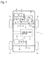
- Fig. 1 is a schematic diagram illustrating the entire configuration of the electric vehicle (hybrid vehicle) with the drive device according to the embodiment of the present invention.
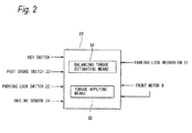
- Fig. 2 is a block diagram illustrating a control state of the drive device according to the embodiment of the present invention.
- Fig. 3 is a timing chart illustrating a time-dependent change in the control of the drive device according to the embodiment of the present invention.
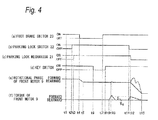
- Fig. 4 is a timing chart when a slope is inclined in an opposite direction.
- a vehicle 1 includes an engine 2, and a generator 3 driven by the engine 2.
- An output system of the engine 2 is connected to an axle 6 of front wheels 5 via a clutch 4.
- a front motor 9 (electric motor) is connected to the generator 3 via an inverter 8, and the front motor 9 is connected to the axle 6 of the front wheels 5.
- the inverter 8 is connected to a high-voltage battery 7, and electrical power stored in the high-voltage battery 7 is supplied to the front motor 9 via the inverter 8.
- an output system 11 of the front motor 9 is connected to the axle 6 via a speed reduction mechanism 12, and the output system of the engine 2 is connected to the output system 11 of the front motor 9 via the clutch 4. Accordingly, the generator 3 is driven by the engine 2, and thereby the high-voltage battery 7 is charged.
- the clutch 4 is engaged, the vehicle 1 travels using the drive force of the engine 2, and when the clutch 4 is disengaged, the vehicle 1 travels using the drive force of the front motor 9.
- a rear motor 17 is connected to the high-voltage battery 7 via an inverter 16 of rear wheels 15, and an output system of the rear motor 17 is connected to a speed reduction mechanism 19 of an axle 18. Electrical power stored in the high-voltage battery 7 is supplied to the rear motor 17 via the inverter 16, and as necessary, the axle 18 (the rear wheels 15) is driven via the speed reduction mechanism 19 by the driving of the rear motor 17.
- the vehicle 1 is equipped with a parking lock mechanism 21 that mechanically locks the rotation of the axle 6 of the front wheels 5.
- a lock pin protrudes and engages with a predetermined portion of a gear member rotating with the axle 6, thereby restricting the rotation of the gear member (rotation of the axle 6). The locking of the rotation of the gear member (rotation of the axle 6) is released by the release of the lock pin.
- a parking lock switch 22 When a gear shift lever is operated so as to be in a parking position (P position), a parking lock switch 22 is electrically operated, and the parking lock mechanism 21 operates and mechanically locks the rotation of the axle 6. Accordingly, even when the vehicle 1 is stopped on an inclined road such as a hill, and a foot brake pedal (service brake pedal) is released, the vehicle 1 does not move due to the weight thereof.
- the vehicle 1 includes a foot brake pedal switch 23 for detecting the operation of the foot brake pedal, and an incline sensor 24 as incline detecting means for detecting an inclined state of the vehicle 1.
- the following information is input into control means 25 illustrated in Fig. 2 : information of a key switch (ignition switch), the foot brake pedal switch 23, the incline sensor 24, and the parking lock switch 22.
- the parking lock mechanism 21 is designed in such a manner that the torsional torque is not rapidly released, and a shock does not occur. That is, the front motor 9 is driven so as to apply torque in the opposite direction of the direction of the torsional torque accumulated in the drive shaft, and thereby the occurrence of a shock is prevented when the torsional torque is released.
- balancing torque is estimated to be torque when the rotational phase of the front motor 9 starts to change.
- toque opposite directional rotational torque
- control means 25 will be described with reference to Fig. 2 .
- control means 25 includes balancing torque estimating means 31, balancing torque storing means, and torque applying means 32.
- the following information is input into the control means 25: detection information of the key switch, the foot brake pedal switch 23, the incline sensor 24, and the parking lock switch 22, and information of the operation of the parking lock mechanism 21.
- a signal indicative of torque being applied is sent to the front motor 9 from the control means 25 so as to obtain the balancing torque, and a state of the rotational phase of the front motor 9 at that time is sent to the control means 25.
- the balancing torque estimating means 31 applies rotational torque to the front motor 9 in the opposite direction of the direction of the torsional torque applied to the drive shaft. For example, when the parking lock mechanism 21 is brought into operation while the vehicle 1 is stopped on a hill facing downward, a torsional force for rotating the front wheels 5 in the forward direction occurs in the drive shaft, and for this reason, torque is applied to the front motor 9 in the rearward rotation direction of the front wheels 5.
- the balancing torque is estimated to be torque when the rotational phase of the front motor 9 starts to change, that is, when the rear wheels 15 start to rotate in the rearward direction.
- the balancing torque storing means stores the balancing torque estimated by the balancing torque estimating means 31.
- the torque applying means 32 applies the balancing torque, stored in the balancing torque storing means, to the front motor 9. For example, since a torsional force for rotating the front wheels 5 in the forward direction is accumulated in the drive shaft, when the parking lock mechanism 21 is released while the vehicle 1 is stopped on a hill facing downward, an accumulated torsional force is released, and a force for rotating the front wheels 5 in the forward direction is exerted, thereby causing the occurrence of a shock.
- the torque applied by the torque applying means 32 is not limited to the balancing torque estimated by the balancing torque estimating means 31, and it is possible to prevent the occurrence of a shock to some extent even when torque (for example, 70% of the balancing torque) calculated based on the balancing torque is applied to the front motor 9.
- Fig. 3 illustrates a state in which the incline sensor 24 determines that the vehicle 1 is stopped on a hill facing downward. Since an incline direction is determined by the incline sensor 24, it is possible to immediately determine the rotation direction of the front motor 9, which is required in order to estimate the balancing torque.
- the key switch is turned off, and the vehicle 1 is brought into a parking state.
- the balancing torque estimating means 31 starts an operation of estimating the balancing torque during a time period from when a signal indicative of the turning-on of the key switch is received at a time t8 to when the parking lock switch 22 is turned off at a time t11. For this reason, it is possible to reliably estimate the balancing torque.
- the balancing torque storing means stores torque Tq at a time t10 as the balancing torque. That is, the balancing torque Tq is equivalent to opposite directional rotational torque that is substantially the same as the accumulated torsional rotational torque. As illustrated in (f) of Fig. 3 , the application of the torque to the front motor 9 is released in order to estimate the balancing torque.
- the parking lock mechanism 21 is brought into a non-operation state, and the mechanical locking of the axle 6 is released.
- the balancing torque Tq is applied to the front motor 9 during a time period (from a time t11 to a time t12) from when the parking lock mechanism 21 is brought into a non-operation state to when the mechanical locking of the axle 6 is released.
- the front motor 9 rotates in the direction in which the vehicle 1 moves forward during a time period from a time t12 to a time t13, and as illustrated in (f) of Fig. 3 , the balancing torque Tq being applied decreases gradually during a time period from a time t12 to a time t13.
- a shock does not occur during a time period from a time t12 to a time t13 as illustrated by the dotted line in (e) of Fig. 3 .
- the balancing torque Tq is estimated to be the torque when the rotational phase of the front motor 9 changes, it is possible to apply the balancing torque Tq (the torque being substantially the same as the torque at the release of the accumulated torsional rotation) to the front motor 9 in the opposite direction. For this reason, the value of the torque Tq can be estimated to be the value of the appropriate torque depending on the situation.
- the balancing torque Tq is estimated by applying torque to the front motor 9, and then the application of the torque for estimating the balancing torque Tq is released, the balancing torque Tq is applied to the front motor 9 so as to prevent the occurrence of a shock. For this reason, it is possible to supply electrical power to the front motor 9 only as necessary, and to prevent the wasting of electrical power.
- the balancing torque Tq is estimated during a time period from when the ignition switch is turned on to when the parking lock switch 22 is electrically turned off, it is possible to estimate the balancing torque Tq before the parking lock mechanism 21 is brought into a non-operation state.
- the balancing torque Tq is applied to the front motor 9 during a time period from when the parking lock switch 22 is electrically turned off to when an operation of releasing the parking lock mechanism 21 occurs, it is possible to apply the balancing torque Tq to the front motor 9 at an appropriate time, and to reliably prevent the occurrence of a shock.
- the balancing torque Tq is applied to the front motor 9 during a time period from a time t11 to a time t12.
- the front motor 9 rotates in the direction in which the vehicle 1 moves rearward during a time period from a time t12 to a time t13, and as illustrated in (f) of Fig. 4 , the balancing torque Tq being applied decreases gradually during a time period from a time t12 to a time t13.
- the torque Tq at a time t10 is estimated as the balancing torque Tq, and in a state where the balancing torque Tq is maintained, as illustrated in (c) of Fig. 5 , at a time t11, the parking lock mechanism 21 is brought into a non-operation state, and the mechanical locking of the axle 6 is released.
- the front motor 9 rotates in the direction in which the vehicle 1 moves forward during a time period from a time t11 to a time t12, and as illustrated in (f) of Fig. 5 , the balancing torque Tq being applied decreases gradually during a time period from a time t11 to a time t12.
- the parking lock mechanism 21 When the parking lock mechanism 21 is brought into a non-operation state, and the mechanical locking of the axle 6 is released, the torsional force accumulated in the drive shaft is released.
- the parking lock mechanism 21 when the parking lock mechanism 21 is brought into a non-operation state, and the mechanical locking of the axle 6 is released (at a time t11), the balancing torque Tq is applied to the front motor 9, and thereby a shock does not occur during a time period from a time t11 to a time t12 as illustrated by the dotted line in (e) of Fig. 5 .
- the balancing torque Tq is estimated by applying torque to the front motor 9 in the opposite direction, and the application of the balancing torque Tq is maintained.
- the parking lock mechanism while the parking lock mechanism is in operation, when rotational torque is applied to the electric motor in the opposite direction of the rotation direction of torsional torque applied to the rotating shaft from the drive wheels to the electric motor, and the balancing torque is estimated based on a state of the rotational phase of the electric motor at that time, and torque equivalent to the estimated balancing torque is applied to the electric motor, thereby preventing the occurrence of a shock from originating during the release of the torsional torque accumulated in the rotating shaft.
- the balancing torque is estimated to be the torque when the rotational phase of the electric motor changes, it is possible to apply the torque (the torque being substantially the same as the torque at the release of the parking lock) to electric motor in the opposite direction.
- the balancing torque is estimated.
- the balancing torque is estimated by applying torque to the electric motor, and then the application of the torque for estimating the balancing torque is released, the balancing torque is applied to the electric motor so as to prevent the occurrence of a shock.
- the balancing torque is estimated by applying torque to the electric motor in the opposite direction during a time period from when the parking lock operating means is released to when the operation of the parking lock mechanism is released.
- the incline detecting means detects and recognizes the torsional rotation direction of a rotating system of the vehicle which is stopped on a hill facing downward or a hill facing upward, and the rotation direction for estimating the balancing torque is determined based on the recognized rotation direction.
- the drive device for an electric vehicle of the present invention can accurately prevent the occurrence of a shock from originating during the release of torsional torque when a parking lock mechanism is released.
- a drive device for an electric vehicle with an electric motor according to the present invention can be applied to various industrial fields.
Landscapes
- Engineering & Computer Science (AREA)
- Power Engineering (AREA)
- Transportation (AREA)
- Mechanical Engineering (AREA)
- Life Sciences & Earth Sciences (AREA)
- Sustainable Development (AREA)
- Sustainable Energy (AREA)
- Electric Propulsion And Braking For Vehicles (AREA)
- Hybrid Electric Vehicles (AREA)
- Control Of Driving Devices And Active Controlling Of Vehicle (AREA)
- Gear-Shifting Mechanisms (AREA)
Applications Claiming Priority (1)
| Application Number | Priority Date | Filing Date | Title |
|---|---|---|---|
| JP2013268024A JP6299956B2 (ja) | 2013-12-25 | 2013-12-25 | 電動車両用駆動装置 |
Publications (3)
| Publication Number | Publication Date |
|---|---|
| EP2902247A2 true EP2902247A2 (fr) | 2015-08-05 |
| EP2902247A3 EP2902247A3 (fr) | 2015-12-30 |
| EP2902247B1 EP2902247B1 (fr) | 2020-01-15 |
Family
ID=52347117
Family Applications (1)
| Application Number | Title | Priority Date | Filing Date |
|---|---|---|---|
| EP14200191.6A Active EP2902247B1 (fr) | 2013-12-25 | 2014-12-23 | Dispositif d'entraînement pour véhicule électrique |
Country Status (3)
| Country | Link |
|---|---|
| US (1) | US9174551B2 (fr) |
| EP (1) | EP2902247B1 (fr) |
| JP (1) | JP6299956B2 (fr) |
Families Citing this family (16)
| Publication number | Priority date | Publication date | Assignee | Title |
|---|---|---|---|---|
| FR3021280B1 (fr) * | 2014-05-21 | 2017-12-22 | Renault Sas | Procede de controle d'un groupe motopropulseur d'un vehicule, dispositif et vehicule correspondant. |
| JP6065890B2 (ja) * | 2014-10-17 | 2017-01-25 | トヨタ自動車株式会社 | 車両の停車中における衝撃検出システムおよび衝撃検出方法 |
| US9931963B2 (en) * | 2015-11-12 | 2018-04-03 | GM Global Technology Operations LLC | Vehicle speed control systems and methods |
| KR101876015B1 (ko) * | 2016-04-14 | 2018-07-06 | 현대자동차주식회사 | 친환경차량의 정차 변속단 해제시 진동 저감 방법 |
| CN107031455B (zh) * | 2017-03-28 | 2019-08-23 | 南京奥联新能源有限公司 | 用于纯电动车的自动防溜车方法 |
| JP6876505B2 (ja) * | 2017-04-25 | 2021-05-26 | マレリ株式会社 | 電動車両の駆動制御装置 |
| CN107284290B (zh) * | 2017-06-20 | 2019-04-26 | 清华大学苏州汽车研究院(吴江) | 纯电动汽车坡道辅助起步控制方法 |
| DE102017221390A1 (de) * | 2017-11-29 | 2019-05-29 | Audi Ag | Verfahren zum Betreiben eines Kraftfahrzeugs sowie entsprechendes Kraftfahrzeug |
| KR20200109886A (ko) * | 2019-03-15 | 2020-09-23 | 현대자동차주식회사 | 전기자동차의 구동계 비틀림 충격 저감 방법 |
| KR102726792B1 (ko) * | 2019-05-03 | 2024-11-05 | 현대자동차주식회사 | 차량의 진동 저감 제어 방법 |
| KR102859895B1 (ko) * | 2019-12-11 | 2025-09-15 | 현대자동차주식회사 | 전기 모터를 구비한 자동차 및 그를 위한 주차 제어 방법 |
| KR20220007773A (ko) * | 2020-07-09 | 2022-01-19 | 현대자동차주식회사 | 하이브리드 자동차 및 그 제어 방법 |
| CN111791719B (zh) * | 2020-07-09 | 2023-04-18 | 中国第一汽车股份有限公司 | 一种车辆的p挡驻车控制方法、电子设备及存储介质 |
| KR102928826B1 (ko) | 2020-08-04 | 2026-02-24 | 현대자동차주식회사 | 전기 모터를 구비한 자동차 및 그를 위한 파킹 기어 해제 방법 |
| JP7616152B2 (ja) * | 2022-05-24 | 2025-01-17 | トヨタ自動車株式会社 | 車両の制御装置 |
| JPWO2024189859A1 (fr) * | 2023-03-15 | 2024-09-19 |
Family Cites Families (14)
| Publication number | Priority date | Publication date | Assignee | Title |
|---|---|---|---|---|
| JP3454009B2 (ja) * | 1996-04-22 | 2003-10-06 | トヨタ自動車株式会社 | 電気自動車のメカニカルパーキングロック装置 |
| JP3262046B2 (ja) * | 1997-09-17 | 2002-03-04 | トヨタ自動車株式会社 | ギヤ機構における歯打ち音の低減方法、動力出力装置およびこの動力出力装置を搭載したハイブリッド車輌 |
| JP3878536B2 (ja) * | 2002-11-05 | 2007-02-07 | 株式会社豊田中央研究所 | ハイブリッド車両の制御装置 |
| JP4385296B2 (ja) * | 2004-08-27 | 2009-12-16 | 富士重工業株式会社 | トラクション制御装置 |
| JP4297135B2 (ja) * | 2006-05-29 | 2009-07-15 | トヨタ自動車株式会社 | 車両用駆動装置の制御装置 |
| JP2008167514A (ja) * | 2006-12-27 | 2008-07-17 | Nissan Motor Co Ltd | 電動車両の制御装置 |
| JP5088103B2 (ja) * | 2007-11-09 | 2012-12-05 | トヨタ自動車株式会社 | 車両の制御装置 |
| JP4910992B2 (ja) * | 2007-11-09 | 2012-04-04 | トヨタ自動車株式会社 | ハイブリッド車両の制御装置 |
| US20090187298A1 (en) * | 2008-01-18 | 2009-07-23 | Cuppetilli Robert D | Vehicle propulsion arrangement |
| JP4998281B2 (ja) * | 2008-01-18 | 2012-08-15 | トヨタ自動車株式会社 | 車両制御装置 |
| JP4341717B2 (ja) * | 2008-01-31 | 2009-10-07 | トヨタ自動車株式会社 | 車両の駆動装置およびその制御方法 |
| WO2010104189A1 (fr) * | 2009-03-09 | 2010-09-16 | Nissan Motor Co., Ltd. | Dispositif de verrouillage de stationnement |
| JP2011098706A (ja) * | 2009-11-09 | 2011-05-19 | Toyota Motor Corp | ハイブリッド車のシフト制御装置 |
| KR20120137131A (ko) * | 2011-06-10 | 2012-12-20 | 현대자동차주식회사 | 자동차 파킹 시스템의 진동 저감용 토크인가장치 및 토크제어방법 |
-
2013
- 2013-12-25 JP JP2013268024A patent/JP6299956B2/ja not_active Expired - Fee Related
-
2014
- 2014-12-23 EP EP14200191.6A patent/EP2902247B1/fr active Active
- 2014-12-23 US US14/581,795 patent/US9174551B2/en active Active
Non-Patent Citations (1)
| Title |
|---|
| None |
Also Published As
| Publication number | Publication date |
|---|---|
| JP6299956B2 (ja) | 2018-03-28 |
| US9174551B2 (en) | 2015-11-03 |
| EP2902247A3 (fr) | 2015-12-30 |
| JP2015126571A (ja) | 2015-07-06 |
| EP2902247B1 (fr) | 2020-01-15 |
| US20150175032A1 (en) | 2015-06-25 |
Similar Documents
| Publication | Publication Date | Title |
|---|---|---|
| EP2902247B1 (fr) | Dispositif d'entraînement pour véhicule électrique | |
| JP5793191B2 (ja) | 自動車用電子パーキングブレーキシステム、及びその補助始動方法 | |
| US7448699B2 (en) | Electro mechanical brake, control device and control methods | |
| CN108454608B (zh) | 在松开制动器的情况下保持发动机自动停止的自定义电驻车制动响应 | |
| US20080086253A1 (en) | Electric parking brake control system and electric parking brake control method | |
| US8862303B2 (en) | Industrial vehicle | |
| JP2017519473A (ja) | 車両のパワートレインを制御する方法、対応する装置及び車両 | |
| US9035591B2 (en) | Control method of electronic parking brake system | |
| CN111086515A (zh) | 机动车辆制动备用系统的运行方法 | |
| CN103038107A (zh) | 用于控制机动车辆的辅助起步装置的方法 | |
| US9694808B2 (en) | Method for a vehicle having an electric machine | |
| US20160311435A1 (en) | Vehicle engine activation control system | |
| JP2010149698A (ja) | 車両用制動力制御装置及びその方法 | |
| KR101870633B1 (ko) | 전자식 주차 브레이크 시스템의 제어 방법 | |
| KR102817285B1 (ko) | 수동 변속기 차량의 원격 시동 방법 및 그 장치 | |
| KR20200065116A (ko) | 차량 및 그 제어 방법 | |
| KR20160148208A (ko) | 전자식 주차 브레이크 시스템 | |
| CN114572006A (zh) | 电子驻车系统的控制方法、装置和车辆 | |
| KR101416367B1 (ko) | 운전자 부재중인 전기자동차의 이동 제어 방법 및 시스템 | |
| CN114889567B (zh) | 一种汽车辅助驻车控制方法、系统、设备、介质及程序 | |
| JP2017065539A (ja) | 車両用停車制御装置 | |
| JP6202269B2 (ja) | 電動車両の制御装置 | |
| JP4978923B2 (ja) | 停止判定装置及び電動パーキングブレーキ制御装置 | |
| JP4164096B2 (ja) | 車両制御システム | |
| KR20170024231A (ko) | 경사로에서의 차량 브레이크 제어 방법 |
Legal Events
| Date | Code | Title | Description |
|---|---|---|---|
| PUAI | Public reference made under article 153(3) epc to a published international application that has entered the european phase |
Free format text: ORIGINAL CODE: 0009012 |
|
| 17P | Request for examination filed |
Effective date: 20141223 |
|
| AK | Designated contracting states |
Kind code of ref document: A2 Designated state(s): AL AT BE BG CH CY CZ DE DK EE ES FI FR GB GR HR HU IE IS IT LI LT LU LV MC MK MT NL NO PL PT RO RS SE SI SK SM TR |
|
| AX | Request for extension of the european patent |
Extension state: BA ME |
|
| PUAL | Search report despatched |
Free format text: ORIGINAL CODE: 0009013 |
|
| AK | Designated contracting states |
Kind code of ref document: A3 Designated state(s): AL AT BE BG CH CY CZ DE DK EE ES FI FR GB GR HR HU IE IS IT LI LT LU LV MC MK MT NL NO PL PT RO RS SE SI SK SM TR |
|
| AX | Request for extension of the european patent |
Extension state: BA ME |
|
| RIC1 | Information provided on ipc code assigned before grant |
Ipc: B60L 15/20 20060101ALI20151124BHEP Ipc: B60L 3/00 20060101AFI20151124BHEP |
|
| RAP1 | Party data changed (applicant data changed or rights of an application transferred) |
Owner name: MITSUBISHI JIDOSHA KOGYO KABUSHIKI KAISHA |
|
| GRAP | Despatch of communication of intention to grant a patent |
Free format text: ORIGINAL CODE: EPIDOSNIGR1 |
|
| STAA | Information on the status of an ep patent application or granted ep patent |
Free format text: STATUS: GRANT OF PATENT IS INTENDED |
|
| INTG | Intention to grant announced |
Effective date: 20190827 |
|
| GRAS | Grant fee paid |
Free format text: ORIGINAL CODE: EPIDOSNIGR3 |
|
| GRAA | (expected) grant |
Free format text: ORIGINAL CODE: 0009210 |
|
| STAA | Information on the status of an ep patent application or granted ep patent |
Free format text: STATUS: THE PATENT HAS BEEN GRANTED |
|
| AK | Designated contracting states |
Kind code of ref document: B1 Designated state(s): AL AT BE BG CH CY CZ DE DK EE ES FI FR GB GR HR HU IE IS IT LI LT LU LV MC MK MT NL NO PL PT RO RS SE SI SK SM TR |
|
| REG | Reference to a national code |
Ref country code: GB Ref legal event code: FG4D Ref country code: CH Ref legal event code: EP |
|
| REG | Reference to a national code |
Ref country code: IE Ref legal event code: FG4D |
|
| REG | Reference to a national code |
Ref country code: AT Ref legal event code: REF Ref document number: 1224875 Country of ref document: AT Kind code of ref document: T Effective date: 20200215 |
|
| REG | Reference to a national code |
Ref country code: DE Ref legal event code: R096 Ref document number: 602014060005 Country of ref document: DE |
|
| REG | Reference to a national code |
Ref country code: NL Ref legal event code: MP Effective date: 20200115 |
|
| REG | Reference to a national code |
Ref country code: LT Ref legal event code: MG4D |
|
| PG25 | Lapsed in a contracting state [announced via postgrant information from national office to epo] |
Ref country code: PT Free format text: LAPSE BECAUSE OF FAILURE TO SUBMIT A TRANSLATION OF THE DESCRIPTION OR TO PAY THE FEE WITHIN THE PRESCRIBED TIME-LIMIT Effective date: 20200607 Ref country code: RS Free format text: LAPSE BECAUSE OF FAILURE TO SUBMIT A TRANSLATION OF THE DESCRIPTION OR TO PAY THE FEE WITHIN THE PRESCRIBED TIME-LIMIT Effective date: 20200115 Ref country code: NL Free format text: LAPSE BECAUSE OF FAILURE TO SUBMIT A TRANSLATION OF THE DESCRIPTION OR TO PAY THE FEE WITHIN THE PRESCRIBED TIME-LIMIT Effective date: 20200115 Ref country code: NO Free format text: LAPSE BECAUSE OF FAILURE TO SUBMIT A TRANSLATION OF THE DESCRIPTION OR TO PAY THE FEE WITHIN THE PRESCRIBED TIME-LIMIT Effective date: 20200415 Ref country code: FI Free format text: LAPSE BECAUSE OF FAILURE TO SUBMIT A TRANSLATION OF THE DESCRIPTION OR TO PAY THE FEE WITHIN THE PRESCRIBED TIME-LIMIT Effective date: 20200115 |
|
| PG25 | Lapsed in a contracting state [announced via postgrant information from national office to epo] |
Ref country code: HR Free format text: LAPSE BECAUSE OF FAILURE TO SUBMIT A TRANSLATION OF THE DESCRIPTION OR TO PAY THE FEE WITHIN THE PRESCRIBED TIME-LIMIT Effective date: 20200115 Ref country code: SE Free format text: LAPSE BECAUSE OF FAILURE TO SUBMIT A TRANSLATION OF THE DESCRIPTION OR TO PAY THE FEE WITHIN THE PRESCRIBED TIME-LIMIT Effective date: 20200115 Ref country code: GR Free format text: LAPSE BECAUSE OF FAILURE TO SUBMIT A TRANSLATION OF THE DESCRIPTION OR TO PAY THE FEE WITHIN THE PRESCRIBED TIME-LIMIT Effective date: 20200416 Ref country code: LV Free format text: LAPSE BECAUSE OF FAILURE TO SUBMIT A TRANSLATION OF THE DESCRIPTION OR TO PAY THE FEE WITHIN THE PRESCRIBED TIME-LIMIT Effective date: 20200115 Ref country code: BG Free format text: LAPSE BECAUSE OF FAILURE TO SUBMIT A TRANSLATION OF THE DESCRIPTION OR TO PAY THE FEE WITHIN THE PRESCRIBED TIME-LIMIT Effective date: 20200415 Ref country code: IS Free format text: LAPSE BECAUSE OF FAILURE TO SUBMIT A TRANSLATION OF THE DESCRIPTION OR TO PAY THE FEE WITHIN THE PRESCRIBED TIME-LIMIT Effective date: 20200515 |
|
| REG | Reference to a national code |
Ref country code: DE Ref legal event code: R097 Ref document number: 602014060005 Country of ref document: DE |
|
| PG25 | Lapsed in a contracting state [announced via postgrant information from national office to epo] |
Ref country code: SK Free format text: LAPSE BECAUSE OF FAILURE TO SUBMIT A TRANSLATION OF THE DESCRIPTION OR TO PAY THE FEE WITHIN THE PRESCRIBED TIME-LIMIT Effective date: 20200115 Ref country code: CZ Free format text: LAPSE BECAUSE OF FAILURE TO SUBMIT A TRANSLATION OF THE DESCRIPTION OR TO PAY THE FEE WITHIN THE PRESCRIBED TIME-LIMIT Effective date: 20200115 Ref country code: RO Free format text: LAPSE BECAUSE OF FAILURE TO SUBMIT A TRANSLATION OF THE DESCRIPTION OR TO PAY THE FEE WITHIN THE PRESCRIBED TIME-LIMIT Effective date: 20200115 Ref country code: ES Free format text: LAPSE BECAUSE OF FAILURE TO SUBMIT A TRANSLATION OF THE DESCRIPTION OR TO PAY THE FEE WITHIN THE PRESCRIBED TIME-LIMIT Effective date: 20200115 Ref country code: LT Free format text: LAPSE BECAUSE OF FAILURE TO SUBMIT A TRANSLATION OF THE DESCRIPTION OR TO PAY THE FEE WITHIN THE PRESCRIBED TIME-LIMIT Effective date: 20200115 Ref country code: DK Free format text: LAPSE BECAUSE OF FAILURE TO SUBMIT A TRANSLATION OF THE DESCRIPTION OR TO PAY THE FEE WITHIN THE PRESCRIBED TIME-LIMIT Effective date: 20200115 Ref country code: EE Free format text: LAPSE BECAUSE OF FAILURE TO SUBMIT A TRANSLATION OF THE DESCRIPTION OR TO PAY THE FEE WITHIN THE PRESCRIBED TIME-LIMIT Effective date: 20200115 Ref country code: SM Free format text: LAPSE BECAUSE OF FAILURE TO SUBMIT A TRANSLATION OF THE DESCRIPTION OR TO PAY THE FEE WITHIN THE PRESCRIBED TIME-LIMIT Effective date: 20200115 |
|
| REG | Reference to a national code |
Ref country code: AT Ref legal event code: MK05 Ref document number: 1224875 Country of ref document: AT Kind code of ref document: T Effective date: 20200115 |
|
| PLBE | No opposition filed within time limit |
Free format text: ORIGINAL CODE: 0009261 |
|
| STAA | Information on the status of an ep patent application or granted ep patent |
Free format text: STATUS: NO OPPOSITION FILED WITHIN TIME LIMIT |
|
| 26N | No opposition filed |
Effective date: 20201016 |
|
| PG25 | Lapsed in a contracting state [announced via postgrant information from national office to epo] |
Ref country code: AT Free format text: LAPSE BECAUSE OF FAILURE TO SUBMIT A TRANSLATION OF THE DESCRIPTION OR TO PAY THE FEE WITHIN THE PRESCRIBED TIME-LIMIT Effective date: 20200115 Ref country code: IT Free format text: LAPSE BECAUSE OF FAILURE TO SUBMIT A TRANSLATION OF THE DESCRIPTION OR TO PAY THE FEE WITHIN THE PRESCRIBED TIME-LIMIT Effective date: 20200115 |
|
| PG25 | Lapsed in a contracting state [announced via postgrant information from national office to epo] |
Ref country code: PL Free format text: LAPSE BECAUSE OF FAILURE TO SUBMIT A TRANSLATION OF THE DESCRIPTION OR TO PAY THE FEE WITHIN THE PRESCRIBED TIME-LIMIT Effective date: 20200115 Ref country code: SI Free format text: LAPSE BECAUSE OF FAILURE TO SUBMIT A TRANSLATION OF THE DESCRIPTION OR TO PAY THE FEE WITHIN THE PRESCRIBED TIME-LIMIT Effective date: 20200115 |
|
| REG | Reference to a national code |
Ref country code: CH Ref legal event code: PL |
|
| PG25 | Lapsed in a contracting state [announced via postgrant information from national office to epo] |
Ref country code: MC Free format text: LAPSE BECAUSE OF FAILURE TO SUBMIT A TRANSLATION OF THE DESCRIPTION OR TO PAY THE FEE WITHIN THE PRESCRIBED TIME-LIMIT Effective date: 20200115 |
|
| REG | Reference to a national code |
Ref country code: BE Ref legal event code: MM Effective date: 20201231 |
|
| PG25 | Lapsed in a contracting state [announced via postgrant information from national office to epo] |
Ref country code: IE Free format text: LAPSE BECAUSE OF NON-PAYMENT OF DUE FEES Effective date: 20201223 Ref country code: LU Free format text: LAPSE BECAUSE OF NON-PAYMENT OF DUE FEES Effective date: 20201223 |
|
| PG25 | Lapsed in a contracting state [announced via postgrant information from national office to epo] |
Ref country code: LI Free format text: LAPSE BECAUSE OF NON-PAYMENT OF DUE FEES Effective date: 20201231 Ref country code: CH Free format text: LAPSE BECAUSE OF NON-PAYMENT OF DUE FEES Effective date: 20201231 |
|
| PG25 | Lapsed in a contracting state [announced via postgrant information from national office to epo] |
Ref country code: TR Free format text: LAPSE BECAUSE OF FAILURE TO SUBMIT A TRANSLATION OF THE DESCRIPTION OR TO PAY THE FEE WITHIN THE PRESCRIBED TIME-LIMIT Effective date: 20200115 Ref country code: MT Free format text: LAPSE BECAUSE OF FAILURE TO SUBMIT A TRANSLATION OF THE DESCRIPTION OR TO PAY THE FEE WITHIN THE PRESCRIBED TIME-LIMIT Effective date: 20200115 Ref country code: CY Free format text: LAPSE BECAUSE OF FAILURE TO SUBMIT A TRANSLATION OF THE DESCRIPTION OR TO PAY THE FEE WITHIN THE PRESCRIBED TIME-LIMIT Effective date: 20200115 |
|
| PG25 | Lapsed in a contracting state [announced via postgrant information from national office to epo] |
Ref country code: MK Free format text: LAPSE BECAUSE OF FAILURE TO SUBMIT A TRANSLATION OF THE DESCRIPTION OR TO PAY THE FEE WITHIN THE PRESCRIBED TIME-LIMIT Effective date: 20200115 Ref country code: AL Free format text: LAPSE BECAUSE OF FAILURE TO SUBMIT A TRANSLATION OF THE DESCRIPTION OR TO PAY THE FEE WITHIN THE PRESCRIBED TIME-LIMIT Effective date: 20200115 |
|
| PG25 | Lapsed in a contracting state [announced via postgrant information from national office to epo] |
Ref country code: BE Free format text: LAPSE BECAUSE OF NON-PAYMENT OF DUE FEES Effective date: 20201231 |
|
| PGFP | Annual fee paid to national office [announced via postgrant information from national office to epo] |
Ref country code: GB Payment date: 20231102 Year of fee payment: 10 |
|
| PGFP | Annual fee paid to national office [announced via postgrant information from national office to epo] |
Ref country code: FR Payment date: 20231108 Year of fee payment: 10 Ref country code: DE Payment date: 20231031 Year of fee payment: 10 |
|
| REG | Reference to a national code |
Ref country code: DE Ref legal event code: R119 Ref document number: 602014060005 Country of ref document: DE |
|
| GBPC | Gb: european patent ceased through non-payment of renewal fee |
Effective date: 20241223 |
|
| PG25 | Lapsed in a contracting state [announced via postgrant information from national office to epo] |
Ref country code: DE Free format text: LAPSE BECAUSE OF NON-PAYMENT OF DUE FEES Effective date: 20250701 |
|
| PG25 | Lapsed in a contracting state [announced via postgrant information from national office to epo] |
Ref country code: GB Free format text: LAPSE BECAUSE OF NON-PAYMENT OF DUE FEES Effective date: 20241223 |
|
| PG25 | Lapsed in a contracting state [announced via postgrant information from national office to epo] |
Ref country code: FR Free format text: LAPSE BECAUSE OF NON-PAYMENT OF DUE FEES Effective date: 20241231 |