EP2902674A2 - Dispositif de transmission de force pour un engrenage - Google Patents
Dispositif de transmission de force pour un engrenage Download PDFInfo
- Publication number
- EP2902674A2 EP2902674A2 EP15153299.1A EP15153299A EP2902674A2 EP 2902674 A2 EP2902674 A2 EP 2902674A2 EP 15153299 A EP15153299 A EP 15153299A EP 2902674 A2 EP2902674 A2 EP 2902674A2
- Authority
- EP
- European Patent Office
- Prior art keywords
- shift lever
- connection
- transmission
- power transmission
- switching
- Prior art date
- Legal status (The legal status is an assumption and is not a legal conclusion. Google has not performed a legal analysis and makes no representation as to the accuracy of the status listed.)
- Granted
Links
Images


Classifications
-
- F—MECHANICAL ENGINEERING; LIGHTING; HEATING; WEAPONS; BLASTING
- F16—ENGINEERING ELEMENTS AND UNITS; GENERAL MEASURES FOR PRODUCING AND MAINTAINING EFFECTIVE FUNCTIONING OF MACHINES OR INSTALLATIONS; THERMAL INSULATION IN GENERAL
- F16H—GEARING
- F16H61/00—Control functions within control units of change-speed- or reversing-gearings for conveying rotary motion ; Control of exclusively fluid gearing, friction gearing, gearings with endless flexible members or other particular types of gearing
- F16H61/26—Generation or transmission of movements for final actuating mechanisms
-
- F—MECHANICAL ENGINEERING; LIGHTING; HEATING; WEAPONS; BLASTING
- F16—ENGINEERING ELEMENTS AND UNITS; GENERAL MEASURES FOR PRODUCING AND MAINTAINING EFFECTIVE FUNCTIONING OF MACHINES OR INSTALLATIONS; THERMAL INSULATION IN GENERAL
- F16H—GEARING
- F16H59/00—Control inputs to control units of change-speed- or reversing-gearings for conveying rotary motion
- F16H59/02—Selector apparatus
- F16H59/04—Ratio selector apparatus
- F16H59/044—Ratio selector apparatus consisting of electrical switches or sensors
-
- B—PERFORMING OPERATIONS; TRANSPORTING
- B62—LAND VEHICLES FOR TRAVELLING OTHERWISE THAN ON RAILS
- B62M—RIDER PROPULSION OF WHEELED VEHICLES OR SLEDGES; POWERED PROPULSION OF SLEDGES OR SINGLE-TRACK CYCLES; TRANSMISSIONS SPECIALLY ADAPTED FOR SUCH VEHICLES
- B62M25/00—Actuators for gearing speed-change mechanisms specially adapted for cycles
- B62M25/02—Actuators for gearing speed-change mechanisms specially adapted for cycles with mechanical transmitting systems, e.g. cables, levers
- B62M25/06—Actuators for gearing speed-change mechanisms specially adapted for cycles with mechanical transmitting systems, e.g. cables, levers foot actuated
-
- F—MECHANICAL ENGINEERING; LIGHTING; HEATING; WEAPONS; BLASTING
- F16—ENGINEERING ELEMENTS AND UNITS; GENERAL MEASURES FOR PRODUCING AND MAINTAINING EFFECTIVE FUNCTIONING OF MACHINES OR INSTALLATIONS; THERMAL INSULATION IN GENERAL
- F16H—GEARING
- F16H61/00—Control functions within control units of change-speed- or reversing-gearings for conveying rotary motion ; Control of exclusively fluid gearing, friction gearing, gearings with endless flexible members or other particular types of gearing
- F16H61/24—Providing feel, e.g. to enable selection
-
- F—MECHANICAL ENGINEERING; LIGHTING; HEATING; WEAPONS; BLASTING
- F16—ENGINEERING ELEMENTS AND UNITS; GENERAL MEASURES FOR PRODUCING AND MAINTAINING EFFECTIVE FUNCTIONING OF MACHINES OR INSTALLATIONS; THERMAL INSULATION IN GENERAL
- F16H—GEARING
- F16H59/00—Control inputs to control units of change-speed- or reversing-gearings for conveying rotary motion
- F16H59/02—Selector apparatus
- F16H2059/0234—Selectors for gearings using foot control
-
- F—MECHANICAL ENGINEERING; LIGHTING; HEATING; WEAPONS; BLASTING
- F16—ENGINEERING ELEMENTS AND UNITS; GENERAL MEASURES FOR PRODUCING AND MAINTAINING EFFECTIVE FUNCTIONING OF MACHINES OR INSTALLATIONS; THERMAL INSULATION IN GENERAL
- F16H—GEARING
- F16H59/00—Control inputs to control units of change-speed- or reversing-gearings for conveying rotary motion
- F16H59/02—Selector apparatus
- F16H2059/0239—Up- and down-shift or range or mode selection by repeated movement
-
- F—MECHANICAL ENGINEERING; LIGHTING; HEATING; WEAPONS; BLASTING
- F16—ENGINEERING ELEMENTS AND UNITS; GENERAL MEASURES FOR PRODUCING AND MAINTAINING EFFECTIVE FUNCTIONING OF MACHINES OR INSTALLATIONS; THERMAL INSULATION IN GENERAL
- F16H—GEARING
- F16H59/00—Control inputs to control units of change-speed- or reversing-gearings for conveying rotary motion
- F16H59/02—Selector apparatus
- F16H2059/0295—Selector apparatus with mechanisms to return lever to neutral or datum position, e.g. by return springs
-
- F—MECHANICAL ENGINEERING; LIGHTING; HEATING; WEAPONS; BLASTING
- F16—ENGINEERING ELEMENTS AND UNITS; GENERAL MEASURES FOR PRODUCING AND MAINTAINING EFFECTIVE FUNCTIONING OF MACHINES OR INSTALLATIONS; THERMAL INSULATION IN GENERAL
- F16H—GEARING
- F16H61/00—Control functions within control units of change-speed- or reversing-gearings for conveying rotary motion ; Control of exclusively fluid gearing, friction gearing, gearings with endless flexible members or other particular types of gearing
- F16H61/24—Providing feel, e.g. to enable selection
- F16H2061/241—Actuators providing feel or simulating a shift gate, i.e. with active force generation for providing counter forces for feed back
-
- F—MECHANICAL ENGINEERING; LIGHTING; HEATING; WEAPONS; BLASTING
- F16—ENGINEERING ELEMENTS AND UNITS; GENERAL MEASURES FOR PRODUCING AND MAINTAINING EFFECTIVE FUNCTIONING OF MACHINES OR INSTALLATIONS; THERMAL INSULATION IN GENERAL
- F16H—GEARING
- F16H61/00—Control functions within control units of change-speed- or reversing-gearings for conveying rotary motion ; Control of exclusively fluid gearing, friction gearing, gearings with endless flexible members or other particular types of gearing
- F16H61/24—Providing feel, e.g. to enable selection
- F16H2061/242—Mechanical shift gates or similar guiding means during selection and shifting
Definitions
- the present invention relates to a power transmission device for a transmission, in particular a motorcycle, with a shift assist system and a method for mounting such a power transmission device.
- a shift assist system is to be understood as supporting the shift between two gears for the vehicle.
- the shift request can be detected and used for a shift preparation.
- Such preparation is aimed, for example, at the synchronization of the gears of the gears to be shifted. This can lead to the extent that, based on this synchronization of the gears to be switched from a geometrical point of view, a coupling process in this Switching can be omitted.
- a shift assistance system can significantly improve the comfort when driving a vehicle, especially a motorcycle.
- the shift assistance system further allows wear within the transmission, in particular corresponding synchronization means, to be reduced or even minimized.
- a shift assistance system can also be used in transmissions without synchronization option.
- a switching request of the driver is necessary as an input parameter. This is to be detected with the highest possible degree of security and in particular to distinguish a desire for an upshift and a desire for a downshift.
- an acceleration or deceleration of the current engine power for a short period of time is ensured by the shift assistance system. It must also be ensured that the corresponding switching request could be transmitted to the switching assistance system before the actual switching operation was carried out.
- the shift request is detected, for example, by spring systems. These are usually located between the shift lever or the shift lever device and the transmission. Such spring devices allow relative movements, which can be done on the shift lever output relative to the transmission input.
- a disadvantage of these solutions is that these additional components must already be taken into account and installed during the manufacture and construction of the vehicle. A retrofitting of such a system is not possible.
- additional space is required for such switching assistance systems, or this switching desire recognition, necessary. Such a space requirement is rarely given especially for vehicles in the form of motorcycles and must be created explicitly by appropriate design.
- additional costs due to this additional component system and corresponding additional weight are a major disadvantage of known solutions.
- a power transmission device for a transmission, in particular a motorcycle, with a shift assistance system has a shift lever device with a bearing device for the movable mounting on a vehicle.
- a power transmission device is characterized in that the shift lever device has a shift lever connection for receiving a shift force, a shift lever for forwarding the shift force and a transmission connection for the delivery of the shift force to the transmission.
- the shift lever on a power storage for the intermediate storage of at least a portion of the switching force, so that a relative movement between the shift lever connection and the transmission connection can be done by changing the stored switching energy in the energy storage.
- a sensor device is provided for the shift lever device for detecting the relative movement between the shift lever connection and the transmission connection.
- a shift lever device is understood to mean that part of the vehicle which is to be understood as a manual interface for receiving the shifting force from the driver.
- the switching device is therefore the treadle, which is arranged for inserting and changing gears at the side of the motorcycle.
- the shift lever device for example, for a motor vehicle in the form of a car, so may be understood by the shift lever device and the gear selector lever inside the vehicle.
- the shift lever devices may also have other technical features.
- the shift lever device of the present invention is divided into three essential sections. These are the shift lever connection, the shift lever and the transmission connection.
- the transmission connection can now forward in a power transmission device according to the invention directly the corresponding switching force in the transmission.
- no separate switching sensor system must be attached to the gearbox connection, so that here no additional space is necessary.
- the shift lever connection serves as an explicit recording option and thus manual interface for the driver of the vehicle.
- the force can be introduced directly or indirectly by means of the foot or hand or other part of the driver's body.
- the shift lever itself is used for forwarding and, in particular, to be able to provide a corresponding lever arm for the shift lever device at a distance from the bearing device. In this way it becomes possible to move the shift lever connection relative to the vehicle.
- two movements are to be distinguished. If the driver of the vehicle wishes to carry out a switching operation for the transmission, he will apply a corresponding shifting force to the shift lever connection and thus set it in motion.
- This general movement is a movement of the shift lever connection relative to the vehicle.
- this movement has two components. On the one hand there is a superordinate component of movement of this shift lever connection relative to the vehicle, on the other hand, depending on the force situation a Relative movement of the shift lever connection also take place to the transmission connection. Subsequently, the function of the energy storage with respect to a switching operation will now be explained in detail in individual steps.
- the driver starts the shift, he increases the shift force on the shift lever connection and starts its relative movement to the vehicle.
- the counterforce to the transmission is still relatively low at the gearbox connection and is not sufficient to initiate the switching process in the way. Accordingly, the transmission port does not move while the shift lever port moves by increasing the shift force.
- This relative movement is permitted due to the fact that the shift lever has a force accumulator within the force path between the shift lever connection and the transmission connection, which enables the accumulating shift force to be stored via the relative movement.
- Increasing the switching force in the memory of the buffer occurs until the force equilibrium at the gearbox connection reaches the necessary switching force.
- this sensor device provides for a bifunctional design.
- the energy accumulator can be designed, for example, in the form of a spring device.
- more complex solutions such as elastomer, fluid or pneumatic solutions in the context of the present invention can be used as energy storage.
- any device which is capable of detecting the defined relative movement between the shift lever connection and the transmission connection can be used as sensor device.
- electrical or electronic sensors such as Hall sensors or resistance sensors can be used here.
- Simple mechanical switches or optical systems are of course conceivable within the meaning of the present invention.
- the core of the sensor device is the possibility of detecting the relative movement, whereby, of course, a redundant design of such a sensor can be advantageous.
- this power transmission device can replace an existing shift lever device on a vehicle, in particular on a motorcycle. It is possible to subsequently prepare or equip existing vehicles or existing transmissions with this detection option for a shift assistance system. With new designs, it is no longer necessary to provide additional space for the corresponding detection function for the switching assistance system. In addition to the reduced complexity, this leads to significantly reduced costs, space savings and weight savings for the transmission or for the vehicle.
- a storage device can be understood as meaning a single or several storage points. This depends on the complexity of the shift lever actually used on the vehicle.
- the Gearbox be formed directly as a bearing device or have the bearing device.
- the bearing device is designed for a rotary bearing.
- the sensor device can work both qualitatively and quantitatively. Thus, it is possible to recognize qualitatively whether or in which direction the relative movement has actually taken place. Quantitative detection may be advantageous if misrecognition is to be avoided. With quantitative detection of the relative movement, it is thus possible to set defined thresholds and even to vary later in order to avoid false tripping with even greater security.
- the energy accumulator can have a spring characteristic to fulfill the corresponding energy storage function.
- the spring characteristic can be designed in particular adjustable or variable.
- the spring characteristic linear, progressive and / or degressive sections or configurations have.
- a power transmission device can be further developed such that the shift lever connection is designed as a stepping lever.
- the shift lever connection is designed as a stepping lever.
- Known gearshift lever devices are usually mounted on the side of motorcycles as pedal lever devices.
- An inventive design of the shift lever connection as a pedal or, accordingly, the shift lever device as a pedal device leads to a retrofit option or a simple equipment option of motorcycles with the functionality of the invention.
- Such tread levers are usually also equipped with a two-sided functionality, so that with both upshifting and downshifting can be performed. Accordingly, bidirectional detection in both directions can be provided by the use of a power transmission device according to the invention.
- the energy accumulator is designed as a rotary energy accumulator, in particular in the form of a rotary spring element, wherein the shift lever connection is designed for a rotational relative movement to the transmission connection.
- a rotational relative movement to the gearbox connection in particular also prefers a rotational relative movement to the entire vehicle for the shift lever connection.
- a correspondingly rotatable force storage device now makes it possible to avoid transferring gears between different forms of movement. Rather, the energy storage can be in direct positive contact with the shift lever connection and the transmission connection, so that a pure torque storage for all relative movements in the energy storage is possible.
- a rotary force accumulator is a torsion spring or the later described torsion bar.
- spring systems or spring devices can provide a corresponding energy storage in the form of spring elements. It is of course also possible that the energy storage in combination of different systems, for example, a spring device together with a pneumatic or hydraulic system, trains.
- damping elements or damping devices can also be present in the energy store.
- the transmission connection has the bearing device.
- the bearing device serves in particular to form a rotary bearing.
- the transmission connection is designed directly for storage of the corresponding stepping lever. If a force transmission device according to the invention is shown the same, then an explicit exchange and thus a retrofitting of the functionality according to the invention for the appropriate motorcycle take place.
- the gearbox is connected directly to the gearbox connection in a storage manner. This can be done further reduction of the parts, the weight and the dimensions.
- a bearing device spaced from the gearbox connection may be useful.
- the shift lever connection has a first axis
- the shift lever has a second axis
- the transmission connection has a third axis
- the first axis for all relative positions of the shift lever connection to the transmission connection spans a plane which is parallel or substantially aligned parallel to the third axis. It is important to pay particular attention to the relative movement of the shift lever connection.
- a plane can be spanned or a plane with a slight curvature. It is crucial that the first axis and the second axis for the corresponding plane have a parallelism to the third axis.
- a correlation with the second axis can be provided at an angle, in particular at right angles. If other angles are provided between the first axis and the second axis or between the third axis and the second axis, then these two angles are preferably the same, so that, as it were, a parallel displacement of the two axes, namely the first axis and the third axis, relative takes place to each other. This can also be referred to as a cranked design of the power transmission device. For a higher degree of freedom can be achieved to adapt a power transmission device according to the invention to different geometric conditions on the respective transmission.
- a switching angle between the orientations of the axis in these two positions results.
- a switching angle of up to 20 ° may be useful, so that when switching in two directions ⁇ 20 ° a range of motion of define a total of about 40 ° for the first axis.
- the adjustment of the switching angle is carried out for the respective switching position based on the force equilibrium. It should be noted that the switching angle depends on the at the time adjusting force balance in the energy storage.
- the shift lever connection has at least one button for contacting by the driver of the vehicle, wherein the button has a surface contour, in particular in the form of a curvature, which correlates with the relative movement of the shift lever connection to the transmission connection.
- the button acts as a manual interface for contacting the foot or the driver's hand. If the shift lever connection is designed, for example, as a stepping lever, then the corresponding button can be formed on the top side and / or on the bottom side. If then a relative rotation of the shift lever connection to the transmission connection, a corresponding curvature in a convex manner as a surface contour can represent a correlation to this relative rotation movement.
- the button is preferably formed on the shift lever connection with a free cut to the foot or the hand a corresponding space in the movement out of the Neutral position in the respective switching position to give.
- the training is provided on both sides in order to achieve the advantages described for both upshifting and downshifting.
- the shift lever connection is designed for a relative movement to the transmission connection from a neutral position to at least one shift position, wherein preferably the energy accumulator in the neutral position exerts a biasing force on the shift lever connection.
- the energy storage has always stored a switching power.
- the minimally stored force is preferably in the neutral position of the shift lever connection and thus in the correlating neutral position of the energy accumulator.
- This minimal switching force in the energy storage can be referred to as a biasing force.
- This biasing force serves to provide a more static feel to the driver and user of the power transmission device at the shift lever port.
- the bias of the energy accumulator is preferably introduced during assembly in the energy storage, so that at this time an adjustment of the bias voltage is preferably possible.
- a further advantage can be achieved if, in a power transmission device according to the invention, the gearbox connection and / or the bearing device have an adapter interface for fastening an adapter for geometric adaptation to a specific vehicle.
- this brings with it a high degree of flexibility as an advantage.
- an adapter in the form of an extension of the lever or a displacement of the axis of rotation can be attached to the adapter interface.
- a power transmission device may preferably already have a corresponding adapter in mounted or fixed manner on this adapter interface.
- the sensor device has at least one detection means, which is arranged stationary to the shift lever connection, and a sensor means, which is arranged stationarily to the transmission connection.
- the detection means serves a corresponding detection possibility for the sensor means. If the sensor device is equipped with a Hall sensor, then the detection means can be fixedly mounted, for example, in the form of a magnet on the shift lever connection.
- the sensor means has the corresponding Hall sensor, which is now arranged stationary on the transmission connection. Accordingly, in the case of the relative movement of the shift lever connection to the transmission connection, there is also a correlating and specific relative movement of the detection means to the sensor means.
- Detection means and / or sensor means can be provided in duplicate for a redundant design.
- the arrangement of the detection means and the sensor means is basically free.
- the sensor means may be disposed on the outside of the shift lever. This can be done front, top, bottom, back or side of the shift lever.
- the sensor element can project at least partially into an opening in the shift lever, in particular radially.
- the detection means could also protrude into such an opening from the inside. It is also possible that the detection means is located completely within an inner tube of the shift lever connection.
- the sensor device is designed to emit the detected relative movement by wireless communication.
- a radio signal can be sent out.
- the necessary energy for this wireless communication can be taken, for example, from an energy store in the form of a battery or a capacitor. It is also possible for the energy store itself or the relative movement between the transmission connection and the selector lever connection to provide energy generation in order to enable this wireless communication.
- a piezoelectric technique called, which can implement a relative movement in a short-term electric current. Cabling is no longer necessary in such an embodiment, so that the corresponding retrofit solution functionality can be made even simpler and more cost-effective.
- the shift lever connection is designed to be foldable relative to the shift lever in a direction different from the possible relative movement to the transmission connection. If the power transmission device according to the invention is arranged, for example, on a motorcycle, contacting of the shift lever connection with the roadway can take place at low cornering positions and accordingly at steep angles of attack. In order to reduce the risk of falling, a corresponding additional foldability in a different direction to the described relative movement to the gearbox connection can reduce the contact or prevent blocking or jamming on the roadway with a corresponding risk of falling.
- the energy accumulator has a torsion bar with a switching end with a switching stop and a transmission end with a gear stop.
- the shift lever connection has a first shift lever connection guide for the shift stop and a second shift lever connection guide for the transmission stop.
- the transmission port includes a first transmission port guide for the shift stop and a second transmission port guide for the transmission stop.
- the power transmission device may be further developed in that the torsion bar at the switching end and / or at the end of the transmission has a mounting interface for the introduction of a torsional force in the torsion bar.
- the mounting interface may be, for example, a non-circular interface.
- a screw ornament interface or a Torx interface can be provided.
- the torsion bar can be twisted and thus provided with a biasing force. In this biased position, the engagement of the shift stop occurs to secure and define this biasing force in the neutral position of the shift lever port.
- the angular position of the shift stop is designed to be variable to the transmission stop.
- a cross hole or staggered bore within the torsion bar may allow two or more possible deployment positions for a shift stop.
- Such a cross bore accordingly allows adjustment or even a later variation of the biasing force of the torsion bar.
- the attacks can be subsequently attached and replaced after a longer period of use.
- the switching device and / or the sensor device has a protection device against the impairment of the sensor device by manual mechanical influence.
- this protection can be used in particular against a contact of the sensor device by the foot of the driver in a motorcycle.
- the protection device may, for example, have a protective shield. Further, it is possible that this protection device at least partially by a housing of the Sensor device is formed.
- the same advantages can be achieved as have been explained in detail with respect to a power transmission device according to the invention.
- the energy storage in kinematic reversal also first on the shift lever connection and last, with charged biasing force, be attached to the transmission connection.
- the multiply explained mounting interface for example in the form of a Torx interface, will be used.
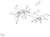
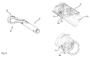
- the Fig. 1 and 2 schematically show a first embodiment of a power transmission device 100 according to the invention.
- This has a shift lever device 10 which can be mounted directly on the side of a motorcycle for the switching of a transmission.
- the attachment takes place via a bearing device 50, which is designed here for rotatory mounting of the shift lever device 10 on the motorcycle.
- the shift lever device 10 is here part of the transmission connection 40, which can introduce a rotational movement and accordingly a torque as a switching force in the transmission.
- the driver of the motorcycle must occur on the shift lever terminal 20 with his foot.
- the shift lever terminal 20 in its neutral position NP according to Fig. 1
- shifting force is introduced into the shift lever connection 20, so that a movement of the shift lever connection 20 relative to the motorcycle can be carried out, as described with reference to FIG Fig. 2 becomes recognizable.
- the dashed line shows the neutral position NP and the solid line shows the switching position SP.
- the shift position SP the shift takes place in the transmission, so that now the corresponding shift force has been passed through the transmission connection.
- a sensor device 60 is shown, which has a sensor means 64.
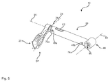
- the Fig. 3 to 5 show the embodiment of the Fig. 1 and 2 without an outer housing and in particular without sensor device 60.
- the three show Fig. 3 to 5 three different positions of the shift lever terminal 20. None of these three positions has However, a switching operation already performed, but all three positions show the situation, just before the switching process is actually carried out.
- Fig. 3 shows the neutral position NP of the shift lever terminal 20.
- corresponding shift stops 72 and gear stops 74 in associated guides 46a and 46b are also in a biased neutral position.
- the detection means 62 displays this neutral position NP. If the driver of the motorcycle now steps onto the shift lever connection 20, a relative rotation of the shift lever connection 20 to the transmission connection 40 takes place, as they do Fig. 5 shows.
- the shift lever terminal 20 moves down, and force must be applied to this relative movement to perform a torsion of the torsion bar 70 within the shift lever 30. This movement can be seen from the altered correlation of the stops 46a and 46b in the guides 72a and 74a.
- the detection means 62 has now moved to a position for the switching position SP.
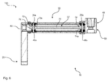
- Fig. 6 is clearly visible in a schematic plan view in cross section, as the energy storage device 32 may be formed in the form of a torsion bar 70.
- the corresponding stops in the form of the shift stop 72a and the gear stop 74 a are arranged at the corresponding switching end 72 and at the transmission end 74.
- Also part of the switching end 72 is a mounting interface 76 with a deviating from the circular cross-section to perform the assembly described later.
- the two stops 72a and 74a are inserted pins to engage the associated guides 46a, 46b, 26a and 26b.
- FIG. 7 shows again the positions according to Fig. 3 to 5 , but in two sections additionally the correlation of the switching end 72 and the transmission end 74 of the torsion bar 70 within the shift lever 30.
- the respective guides are elongated holes which overlap one another.
- Fig. 7 the neutral position NP of the shift lever terminal 20 is shown.
- the shift stop 72a At the switching end 72 of the torsion bar 70 is the shift stop 72a in a position in which the freewheel of the two guides 26a and 46a is given up.
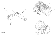
- the Fig. 10 . 11 and 12 show a mounting option for a power transmission device 100 according to the invention.
- the assembly is carried out by inserting the torsion bar 70 in the shift lever connection 20.
- two mutually offset at an angle holes at the switching end 72 and the transmission end 74 of the torsion bar 70 can be seen.
- the transmission connection 40 and thus the shift lever 30 are pushed on, so that a gear stop 74a can finally be used as a pin for this step.
- a gear stop 74a can finally be used as a pin for this step.
- a gear stop 74a can finally be used as a pin for this step.
- a gear stop 74a can finally be used as a pin for this step.
- a prestressing force in the form of a torsion can now be introduced into the torsion bar 70 at the mounting interface 76.
- the corresponding designed as a pin switching stopper 72a is inserted and thus fixes the biasing force.
- Final will be according to Fig. 12 still a cover 80 placed on, to ensure a water-tightness and a magnet as a detection means 62 attached. If now still the waterproof splashed housing of the sensor device 60 is pushed over, the power transmission device 100 is finalized and has a shape, such as the Fig. 1 and 2 demonstrate.
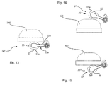
- FIGS. 13, 14 and 15 three different positions are shown, in which the shift lever terminal 20 is formed as a pedal of a motorcycle.
- the buttons 22 each have a surface contour 22a in a curved manner, so that the foot 300 does not have to tilt.
- the relative rotation thus results in a consistent contact position with the foot 300, wherein the risk of slipping with the foot 300 is reduced or even minimized.
- radially spaced from the corresponding force memory 32 to the shift lever port 20 free cuts 22b can be seen to give the foot 300 the corresponding range of motion for the implementation of the respective switching movement.
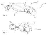
- FIGS. 16 and 17 a further embodiment of a shift lever device 10 according to the invention is shown.
- a protective device 90 in the form of a protective shield.
- the wiring which extends to the sensor device 60 is also at least partially covered by the protective shield of the protective device 90 with.
Landscapes
- Engineering & Computer Science (AREA)
- General Engineering & Computer Science (AREA)
- Mechanical Engineering (AREA)
- Chemical & Material Sciences (AREA)
- Combustion & Propulsion (AREA)
- Transportation (AREA)
- Gear-Shifting Mechanisms (AREA)
Applications Claiming Priority (1)
| Application Number | Priority Date | Filing Date | Title |
|---|---|---|---|
| DE102014101189.9A DE102014101189B4 (de) | 2014-01-31 | 2014-01-31 | Kraftübertragungsvorrichtung für ein Getriebe und Montageverfahren |
Publications (3)
| Publication Number | Publication Date |
|---|---|
| EP2902674A2 true EP2902674A2 (fr) | 2015-08-05 |
| EP2902674A3 EP2902674A3 (fr) | 2015-10-21 |
| EP2902674B1 EP2902674B1 (fr) | 2020-10-07 |
Family
ID=52446231
Family Applications (2)
| Application Number | Title | Priority Date | Filing Date |
|---|---|---|---|
| EP15153299.1A Active EP2902674B1 (fr) | 2014-01-31 | 2015-01-30 | Dispositif de transmission de force pour un engrenage |
| EP15704484.3A Active EP3099960B1 (fr) | 2014-01-31 | 2015-01-30 | Dispositif de transfert de puissance pour une boîte de vitesses |
Family Applications After (1)
| Application Number | Title | Priority Date | Filing Date |
|---|---|---|---|
| EP15704484.3A Active EP3099960B1 (fr) | 2014-01-31 | 2015-01-30 | Dispositif de transfert de puissance pour une boîte de vitesses |
Country Status (5)
| Country | Link |
|---|---|
| US (1) | US10975956B2 (fr) |
| EP (2) | EP2902674B1 (fr) |
| JP (1) | JP6518695B2 (fr) |
| DE (1) | DE102014101189B4 (fr) |
| WO (1) | WO2015114109A1 (fr) |
Cited By (1)
| Publication number | Priority date | Publication date | Assignee | Title |
|---|---|---|---|---|
| US10975956B2 (en) | 2014-01-31 | 2021-04-13 | Hs Products Engineering Gmbh | Force transmission device for a transmission |
Families Citing this family (6)
| Publication number | Priority date | Publication date | Assignee | Title |
|---|---|---|---|---|
| DE102015114338A1 (de) | 2015-08-28 | 2017-03-02 | Ktm Ag | Schalteinrichtung zur Betätigung eines Schaltgetriebes eines Motorrads zur Durchführung eines Gangwechsels bei geschlossener Kupplung |
| JP6668127B2 (ja) * | 2016-03-18 | 2020-03-18 | 本田技研工業株式会社 | 車両用変速機構造 |
| DE102016115367A1 (de) * | 2016-08-18 | 2018-02-22 | Hs Products Engineering Gmbh | Kraftübertragungsvorrichtung für ein Getriebe mit einem Schaltassistenzsystem |
| DE102017107008A1 (de) * | 2017-03-31 | 2018-10-04 | Koki Technik Transmission Systems Gmbh | Handschaltung für ein Fahrzeuggetriebe |
| NO346302B1 (en) * | 2020-09-29 | 2022-05-30 | Ca Tech Systems As | Vehicle gear shift system |
| JP7485300B2 (ja) * | 2020-11-26 | 2024-05-16 | 朝日電装株式会社 | シフト装置 |
Family Cites Families (36)
| Publication number | Priority date | Publication date | Assignee | Title |
|---|---|---|---|---|
| US3129571A (en) * | 1962-01-03 | 1964-04-21 | Ingersoll Rand Co | Impact tool torque limiting control |
| FR1373805A (fr) * | 1963-08-20 | 1964-10-02 | Renault | Dispositif de transmission élastique anti-vibratoire |
| DE1927842B2 (de) * | 1969-05-31 | 1971-05-19 | Einrichtung zur uebertragung einer drehbewegung durch die wand eines unter druck stehenden raumes | |
| GB1448101A (en) * | 1973-02-03 | 1976-09-02 | Lucas Industries Ltd | Torque transmitting device with torque limiting brake |
| FR2250403A5 (fr) * | 1973-08-30 | 1975-05-30 | Dossier Michel | |
| IT1045146B (it) * | 1975-07-21 | 1980-05-10 | Grandis Ugolino | Dispositivo per l azionamento a pedale del comando del cambio di velocita di autoveicolo particolarmente per motoveicoli dotati di cambio di velocita dotati di cambio di velocita di tipo automo bilistico |
| GB2138100B (en) * | 1983-03-18 | 1987-02-11 | Steven Odobasic | Laminated tubular link |
| GB2165333A (en) * | 1984-09-26 | 1986-04-09 | Steven Odobasic | Laminated torsion elements |
| US4884790A (en) * | 1988-06-01 | 1989-12-05 | Paul Castrilli | Nonlinear torsion spring |
| EP0445828B1 (fr) * | 1990-03-09 | 1994-12-28 | Honda Giken Kogyo Kabushiki Kaisha | Système de changement de vitesse pour automobile |
| JPH072125A (ja) * | 1993-04-22 | 1995-01-06 | Toyota Motor Corp | パワーステアリング用トーションバー |
| DE19680043D2 (de) * | 1995-06-19 | 1997-08-21 | Trw Fahrwerksyst Gmbh & Co | Torsionselement für Lenkventile und Verfahren zur Verbesserung der Federcharakteristik |
| US5692992A (en) * | 1996-02-14 | 1997-12-02 | Volva Penta Of The Americas, Inc. | Shift assist and engine interrupter apparatus |
| SE512576C2 (sv) * | 1997-08-25 | 2000-04-03 | Volvo Penta Ab | Anordning för assisterad växling vid transmission |
| DE29812605U1 (de) | 1998-07-15 | 1998-09-17 | Scheffler, Burkhard, 28719 Bremen | Schaltvorrichtung für ein Motorradgetriebe |
| IT1310731B1 (it) | 1999-11-23 | 2002-02-22 | Campagnolo Srl | Dispositivo di cambio di velocita' per biciclette. |
| US6308797B1 (en) * | 2000-07-20 | 2001-10-30 | Harley-Davidson Motor Company Group | Motorcycle transmission shifter mechanism |
| US6659911B2 (en) * | 2000-11-28 | 2003-12-09 | Yamaha Marine Kabushiki Kaisha | Shift assist system for an outboard motor |
| JP4145139B2 (ja) * | 2002-12-26 | 2008-09-03 | 本田技研工業株式会社 | 変速機のギアポジション検知装置の配置構造 |
| EP1571378B1 (fr) * | 2004-03-02 | 2008-02-20 | Getrag Ford Transmissions GmbH | Mécanisme de commande de changement de vitesse pour transmission automatisée |
| US7581467B2 (en) | 2005-07-11 | 2009-09-01 | Team Industries, Inc. | Transmission |
| JP5010903B2 (ja) | 2006-12-01 | 2012-08-29 | 株式会社日立産機システム | モータ及びそれを用いたファン |
| US7747372B2 (en) * | 2007-07-03 | 2010-06-29 | Toyota Motor Engineering & Manufacturing North America, Inc. | Systems and methods for user control of vehicular transmission shift points |
| FR2920178B1 (fr) * | 2007-08-20 | 2009-10-30 | Aircelle Sa | Dispositif de liaison, destine a relier un premier et un second elements articules l'un par rapport a l'autre |
| US8452498B2 (en) * | 2008-03-31 | 2013-05-28 | GM Global Technology Operations LLC | Shifting system with tactile feedback |
| JP5002516B2 (ja) | 2008-04-03 | 2012-08-15 | 本田技研工業株式会社 | 変速装置及び自動二輪車 |
| JP5061383B2 (ja) | 2008-05-13 | 2012-10-31 | 本田技研工業株式会社 | 変速機の変速制御装置 |
| US8573621B1 (en) * | 2009-02-18 | 2013-11-05 | Norman Reynolds | Integrated composite torsion cartridge |
| US8505888B2 (en) * | 2009-12-01 | 2013-08-13 | Impulse Composites, Llc | Tubular torsion bar |
| JP5373678B2 (ja) | 2010-03-18 | 2013-12-18 | 本田技研工業株式会社 | 鞍乗り型車両の変速制御装置 |
| DE102010015037B4 (de) * | 2010-04-15 | 2020-07-02 | Bayerische Motoren Werke Aktiengesellschaft | Schalteinrichtung für Motorräder |
| US9228626B2 (en) * | 2010-11-29 | 2016-01-05 | Todd Michael Whitaker | Tubular torsion bar |
| DE102011052494B3 (de) * | 2011-08-08 | 2012-10-31 | Hs Products Engineering Gmbh | Kraftübertragungsvorrichtung für ein Getriebe mit einem Schaltassistenzsystem |
| DE102012209720B4 (de) * | 2012-06-11 | 2017-09-14 | Bayerische Motoren Werke Aktiengesellschaft | Schalteinrichtung |
| DE102012209963A1 (de) * | 2012-06-14 | 2013-12-19 | Robert Bosch Gmbh | Motorradschaltung mit Schaltassistent zum Schalten ohne Kupplungsbetätigung und Verfahren hierzu |
| DE102014101189B4 (de) | 2014-01-31 | 2019-07-25 | Hs Products Engineering Gmbh | Kraftübertragungsvorrichtung für ein Getriebe und Montageverfahren |
-
2014
- 2014-01-31 DE DE102014101189.9A patent/DE102014101189B4/de not_active Expired - Fee Related
-
2015
- 2015-01-30 JP JP2016567155A patent/JP6518695B2/ja not_active Expired - Fee Related
- 2015-01-30 US US15/115,508 patent/US10975956B2/en active Active
- 2015-01-30 WO PCT/EP2015/051977 patent/WO2015114109A1/fr not_active Ceased
- 2015-01-30 EP EP15153299.1A patent/EP2902674B1/fr active Active
- 2015-01-30 EP EP15704484.3A patent/EP3099960B1/fr active Active
Non-Patent Citations (1)
| Title |
|---|
| None |
Cited By (1)
| Publication number | Priority date | Publication date | Assignee | Title |
|---|---|---|---|---|
| US10975956B2 (en) | 2014-01-31 | 2021-04-13 | Hs Products Engineering Gmbh | Force transmission device for a transmission |
Also Published As
| Publication number | Publication date |
|---|---|
| DE102014101189A1 (de) | 2015-08-06 |
| EP3099960B1 (fr) | 2017-11-29 |
| DE102014101189B4 (de) | 2019-07-25 |
| EP3099960A1 (fr) | 2016-12-07 |
| JP2017507306A (ja) | 2017-03-16 |
| JP6518695B2 (ja) | 2019-05-22 |
| US10975956B2 (en) | 2021-04-13 |
| US20170254410A1 (en) | 2017-09-07 |
| WO2015114109A1 (fr) | 2015-08-06 |
| EP2902674A3 (fr) | 2015-10-21 |
| EP2902674B1 (fr) | 2020-10-07 |
Similar Documents
| Publication | Publication Date | Title |
|---|---|---|
| DE102014101189B4 (de) | Kraftübertragungsvorrichtung für ein Getriebe und Montageverfahren | |
| DE102010015036B4 (de) | Schalteinrichtung für Motorräder | |
| EP3571428B1 (fr) | Dispositif permettant de faire coulisser un élément de passage de vitesse et boîte de vitesses | |
| EP1924788B1 (fr) | Dispositif de commande a element de commutation supplementaire | |
| DE102013215784A1 (de) | Fahrradantrieb und Fahrrad mit Fahrradantrieb | |
| DE102004046946B4 (de) | Verfahren zur Montage eines Lenkwinkel- und Lenkmomentsensors sowie Lenkgetriebe mit einem Lenkwinkel- und Lenkmomentsensor | |
| DE4204946A1 (de) | Polarisierter schalthebel zur betaetigung eines schaltgetriebes, insbesondere fuer kraftfahrzeuge | |
| WO2012152445A1 (fr) | Dispositif de commande | |
| DE102009024821A1 (de) | Schaltvorrichtung | |
| DE19913835C2 (de) | Schaltvorrichtung für Kraftfahrzeuge | |
| DE102009044411B4 (de) | Steckkombinationsstruktur eines Schaltknopfs eines Automatikgetriebes | |
| DE102013013406B4 (de) | Vorrichtung zur automatischen Steuerung der Höheneinstellung eines Sattels und weiterer Funktonen an einem Fahrrad mit und ohne Motoruntersstützung | |
| DE102011053366A1 (de) | Schaltanordnung sowie ein damit ausgestattetes Zahnräderwechselgetriebe | |
| DE10029620B4 (de) | Schaltwelle für ein Schaltgetriebe und Verfahren zu ihrer Herstellung | |
| DE102004060232A1 (de) | Elektrische Schalteinrichtung für ein automatisiertes Getriebe | |
| DE102014103789B4 (de) | Schaltvorrichtung für ein Getriebe | |
| EP2569557A1 (fr) | Dispositif pour transmettre un mouvement de commande | |
| DE102014211427A1 (de) | Sensoraufnahme für einen hydraulischen Zylinder und Verfahren zum Fixieren eines Sensors | |
| EP1300614A2 (fr) | Méthode de détection de la position neutre d'une transmission robotisée | |
| DE10359326A1 (de) | Parksperre eines Automatgetriebes | |
| WO2004010032A1 (fr) | Actionneur electromecanique de boite de vitesses | |
| DE102017113625A1 (de) | Variabel adaptive Kraft-Weg-Kennlinie an einem Betätigungselement | |
| EP2060831B1 (fr) | Dispositif de commutation séquentiel | |
| DE10249845B4 (de) | Steuerungsvorrichtung für Fahrzeug-Dachsysteme | |
| DE102015102364B4 (de) | Schaltwellenmodul für ein Getriebe eines Kraftfahrzeuges |
Legal Events
| Date | Code | Title | Description |
|---|---|---|---|
| PUAI | Public reference made under article 153(3) epc to a published international application that has entered the european phase |
Free format text: ORIGINAL CODE: 0009012 |
|
| 17P | Request for examination filed |
Effective date: 20150130 |
|
| AK | Designated contracting states |
Kind code of ref document: A2 Designated state(s): AL AT BE BG CH CY CZ DE DK EE ES FI FR GB GR HR HU IE IS IT LI LT LU LV MC MK MT NL NO PL PT RO RS SE SI SK SM TR |
|
| AX | Request for extension of the european patent |
Extension state: BA ME |
|
| PUAL | Search report despatched |
Free format text: ORIGINAL CODE: 0009013 |
|
| AK | Designated contracting states |
Kind code of ref document: A3 Designated state(s): AL AT BE BG CH CY CZ DE DK EE ES FI FR GB GR HR HU IE IS IT LI LT LU LV MC MK MT NL NO PL PT RO RS SE SI SK SM TR |
|
| AX | Request for extension of the european patent |
Extension state: BA ME |
|
| RIC1 | Information provided on ipc code assigned before grant |
Ipc: F16H 61/24 20060101ALN20150914BHEP Ipc: F16H 61/26 20060101AFI20150914BHEP |
|
| 17P | Request for examination filed |
Effective date: 20160204 |
|
| RBV | Designated contracting states (corrected) |
Designated state(s): AL AT BE BG CH CY CZ DE DK EE ES FI FR GB GR HR HU IE IS IT LI LT LU LV MC MK MT NL NO PL PT RO RS SE SI SK SM TR |
|
| STAA | Information on the status of an ep patent application or granted ep patent |
Free format text: STATUS: EXAMINATION IS IN PROGRESS |
|
| 17Q | First examination report despatched |
Effective date: 20191112 |
|
| GRAP | Despatch of communication of intention to grant a patent |
Free format text: ORIGINAL CODE: EPIDOSNIGR1 |
|
| STAA | Information on the status of an ep patent application or granted ep patent |
Free format text: STATUS: GRANT OF PATENT IS INTENDED |
|
| RIC1 | Information provided on ipc code assigned before grant |
Ipc: F16H 61/26 20060101AFI20200520BHEP Ipc: F16H 61/24 20060101ALN20200520BHEP |
|
| RIC1 | Information provided on ipc code assigned before grant |
Ipc: F16H 61/26 20060101AFI20200527BHEP Ipc: F16H 61/24 20060101ALN20200527BHEP |
|
| INTG | Intention to grant announced |
Effective date: 20200623 |
|
| GRAS | Grant fee paid |
Free format text: ORIGINAL CODE: EPIDOSNIGR3 |
|
| GRAA | (expected) grant |
Free format text: ORIGINAL CODE: 0009210 |
|
| STAA | Information on the status of an ep patent application or granted ep patent |
Free format text: STATUS: THE PATENT HAS BEEN GRANTED |
|
| AK | Designated contracting states |
Kind code of ref document: B1 Designated state(s): AL AT BE BG CH CY CZ DE DK EE ES FI FR GB GR HR HU IE IS IT LI LT LU LV MC MK MT NL NO PL PT RO RS SE SI SK SM TR |
|
| REG | Reference to a national code |
Ref country code: GB Ref legal event code: FG4D Free format text: NOT ENGLISH |
|
| REG | Reference to a national code |
Ref country code: AT Ref legal event code: REF Ref document number: 1321480 Country of ref document: AT Kind code of ref document: T Effective date: 20201015 Ref country code: CH Ref legal event code: EP |
|
| REG | Reference to a national code |
Ref country code: IE Ref legal event code: FG4D Free format text: LANGUAGE OF EP DOCUMENT: GERMAN |
|
| REG | Reference to a national code |
Ref country code: DE Ref legal event code: R096 Ref document number: 502015013583 Country of ref document: DE |
|
| REG | Reference to a national code |
Ref country code: NL Ref legal event code: MP Effective date: 20201007 |
|
| PG25 | Lapsed in a contracting state [announced via postgrant information from national office to epo] |
Ref country code: RS Free format text: LAPSE BECAUSE OF FAILURE TO SUBMIT A TRANSLATION OF THE DESCRIPTION OR TO PAY THE FEE WITHIN THE PRESCRIBED TIME-LIMIT Effective date: 20201007 Ref country code: FI Free format text: LAPSE BECAUSE OF FAILURE TO SUBMIT A TRANSLATION OF THE DESCRIPTION OR TO PAY THE FEE WITHIN THE PRESCRIBED TIME-LIMIT Effective date: 20201007 Ref country code: NO Free format text: LAPSE BECAUSE OF FAILURE TO SUBMIT A TRANSLATION OF THE DESCRIPTION OR TO PAY THE FEE WITHIN THE PRESCRIBED TIME-LIMIT Effective date: 20210107 Ref country code: PT Free format text: LAPSE BECAUSE OF FAILURE TO SUBMIT A TRANSLATION OF THE DESCRIPTION OR TO PAY THE FEE WITHIN THE PRESCRIBED TIME-LIMIT Effective date: 20210208 Ref country code: NL Free format text: LAPSE BECAUSE OF FAILURE TO SUBMIT A TRANSLATION OF THE DESCRIPTION OR TO PAY THE FEE WITHIN THE PRESCRIBED TIME-LIMIT Effective date: 20201007 Ref country code: GR Free format text: LAPSE BECAUSE OF FAILURE TO SUBMIT A TRANSLATION OF THE DESCRIPTION OR TO PAY THE FEE WITHIN THE PRESCRIBED TIME-LIMIT Effective date: 20210108 |
|
| REG | Reference to a national code |
Ref country code: LT Ref legal event code: MG4D |
|
| PG25 | Lapsed in a contracting state [announced via postgrant information from national office to epo] |
Ref country code: LV Free format text: LAPSE BECAUSE OF FAILURE TO SUBMIT A TRANSLATION OF THE DESCRIPTION OR TO PAY THE FEE WITHIN THE PRESCRIBED TIME-LIMIT Effective date: 20201007 Ref country code: PL Free format text: LAPSE BECAUSE OF FAILURE TO SUBMIT A TRANSLATION OF THE DESCRIPTION OR TO PAY THE FEE WITHIN THE PRESCRIBED TIME-LIMIT Effective date: 20201007 Ref country code: IS Free format text: LAPSE BECAUSE OF FAILURE TO SUBMIT A TRANSLATION OF THE DESCRIPTION OR TO PAY THE FEE WITHIN THE PRESCRIBED TIME-LIMIT Effective date: 20210207 Ref country code: SE Free format text: LAPSE BECAUSE OF FAILURE TO SUBMIT A TRANSLATION OF THE DESCRIPTION OR TO PAY THE FEE WITHIN THE PRESCRIBED TIME-LIMIT Effective date: 20201007 Ref country code: ES Free format text: LAPSE BECAUSE OF FAILURE TO SUBMIT A TRANSLATION OF THE DESCRIPTION OR TO PAY THE FEE WITHIN THE PRESCRIBED TIME-LIMIT Effective date: 20201007 Ref country code: BG Free format text: LAPSE BECAUSE OF FAILURE TO SUBMIT A TRANSLATION OF THE DESCRIPTION OR TO PAY THE FEE WITHIN THE PRESCRIBED TIME-LIMIT Effective date: 20210107 |
|
| PG25 | Lapsed in a contracting state [announced via postgrant information from national office to epo] |
Ref country code: HR Free format text: LAPSE BECAUSE OF FAILURE TO SUBMIT A TRANSLATION OF THE DESCRIPTION OR TO PAY THE FEE WITHIN THE PRESCRIBED TIME-LIMIT Effective date: 20201007 |
|
| REG | Reference to a national code |
Ref country code: DE Ref legal event code: R097 Ref document number: 502015013583 Country of ref document: DE |
|
| PG25 | Lapsed in a contracting state [announced via postgrant information from national office to epo] |
Ref country code: SM Free format text: LAPSE BECAUSE OF FAILURE TO SUBMIT A TRANSLATION OF THE DESCRIPTION OR TO PAY THE FEE WITHIN THE PRESCRIBED TIME-LIMIT Effective date: 20201007 Ref country code: EE Free format text: LAPSE BECAUSE OF FAILURE TO SUBMIT A TRANSLATION OF THE DESCRIPTION OR TO PAY THE FEE WITHIN THE PRESCRIBED TIME-LIMIT Effective date: 20201007 Ref country code: CZ Free format text: LAPSE BECAUSE OF FAILURE TO SUBMIT A TRANSLATION OF THE DESCRIPTION OR TO PAY THE FEE WITHIN THE PRESCRIBED TIME-LIMIT Effective date: 20201007 Ref country code: LT Free format text: LAPSE BECAUSE OF FAILURE TO SUBMIT A TRANSLATION OF THE DESCRIPTION OR TO PAY THE FEE WITHIN THE PRESCRIBED TIME-LIMIT Effective date: 20201007 Ref country code: RO Free format text: LAPSE BECAUSE OF FAILURE TO SUBMIT A TRANSLATION OF THE DESCRIPTION OR TO PAY THE FEE WITHIN THE PRESCRIBED TIME-LIMIT Effective date: 20201007 Ref country code: SK Free format text: LAPSE BECAUSE OF FAILURE TO SUBMIT A TRANSLATION OF THE DESCRIPTION OR TO PAY THE FEE WITHIN THE PRESCRIBED TIME-LIMIT Effective date: 20201007 |
|
| PLBE | No opposition filed within time limit |
Free format text: ORIGINAL CODE: 0009261 |
|
| STAA | Information on the status of an ep patent application or granted ep patent |
Free format text: STATUS: NO OPPOSITION FILED WITHIN TIME LIMIT |
|
| PG25 | Lapsed in a contracting state [announced via postgrant information from national office to epo] |
Ref country code: DK Free format text: LAPSE BECAUSE OF FAILURE TO SUBMIT A TRANSLATION OF THE DESCRIPTION OR TO PAY THE FEE WITHIN THE PRESCRIBED TIME-LIMIT Effective date: 20201007 Ref country code: MC Free format text: LAPSE BECAUSE OF FAILURE TO SUBMIT A TRANSLATION OF THE DESCRIPTION OR TO PAY THE FEE WITHIN THE PRESCRIBED TIME-LIMIT Effective date: 20201007 |
|
| REG | Reference to a national code |
Ref country code: CH Ref legal event code: PL |
|
| 26N | No opposition filed |
Effective date: 20210708 |
|
| GBPC | Gb: european patent ceased through non-payment of renewal fee |
Effective date: 20210130 |
|
| PG25 | Lapsed in a contracting state [announced via postgrant information from national office to epo] |
Ref country code: LU Free format text: LAPSE BECAUSE OF NON-PAYMENT OF DUE FEES Effective date: 20210130 |
|
| REG | Reference to a national code |
Ref country code: BE Ref legal event code: MM Effective date: 20210131 |
|
| PG25 | Lapsed in a contracting state [announced via postgrant information from national office to epo] |
Ref country code: AL Free format text: LAPSE BECAUSE OF FAILURE TO SUBMIT A TRANSLATION OF THE DESCRIPTION OR TO PAY THE FEE WITHIN THE PRESCRIBED TIME-LIMIT Effective date: 20201007 Ref country code: FR Free format text: LAPSE BECAUSE OF NON-PAYMENT OF DUE FEES Effective date: 20210131 |
|
| PG25 | Lapsed in a contracting state [announced via postgrant information from national office to epo] |
Ref country code: SI Free format text: LAPSE BECAUSE OF FAILURE TO SUBMIT A TRANSLATION OF THE DESCRIPTION OR TO PAY THE FEE WITHIN THE PRESCRIBED TIME-LIMIT Effective date: 20201007 Ref country code: CH Free format text: LAPSE BECAUSE OF NON-PAYMENT OF DUE FEES Effective date: 20210131 Ref country code: GB Free format text: LAPSE BECAUSE OF NON-PAYMENT OF DUE FEES Effective date: 20210130 Ref country code: LI Free format text: LAPSE BECAUSE OF NON-PAYMENT OF DUE FEES Effective date: 20210131 |
|
| PG25 | Lapsed in a contracting state [announced via postgrant information from national office to epo] |
Ref country code: IE Free format text: LAPSE BECAUSE OF NON-PAYMENT OF DUE FEES Effective date: 20210130 |
|
| PG25 | Lapsed in a contracting state [announced via postgrant information from national office to epo] |
Ref country code: IS Free format text: LAPSE BECAUSE OF FAILURE TO SUBMIT A TRANSLATION OF THE DESCRIPTION OR TO PAY THE FEE WITHIN THE PRESCRIBED TIME-LIMIT Effective date: 20210207 |
|
| PG25 | Lapsed in a contracting state [announced via postgrant information from national office to epo] |
Ref country code: BE Free format text: LAPSE BECAUSE OF NON-PAYMENT OF DUE FEES Effective date: 20210131 |
|
| REG | Reference to a national code |
Ref country code: DE Ref legal event code: R082 Ref document number: 502015013583 Country of ref document: DE Representative=s name: MATHYS & SQUIRE EUROPE PATENTANWAELTE PARTNERS, DE |
|
| PG25 | Lapsed in a contracting state [announced via postgrant information from national office to epo] |
Ref country code: HU Free format text: LAPSE BECAUSE OF FAILURE TO SUBMIT A TRANSLATION OF THE DESCRIPTION OR TO PAY THE FEE WITHIN THE PRESCRIBED TIME-LIMIT; INVALID AB INITIO Effective date: 20150130 |
|
| PG25 | Lapsed in a contracting state [announced via postgrant information from national office to epo] |
Ref country code: CY Free format text: LAPSE BECAUSE OF FAILURE TO SUBMIT A TRANSLATION OF THE DESCRIPTION OR TO PAY THE FEE WITHIN THE PRESCRIBED TIME-LIMIT Effective date: 20201007 |
|
| PG25 | Lapsed in a contracting state [announced via postgrant information from national office to epo] |
Ref country code: MK Free format text: LAPSE BECAUSE OF FAILURE TO SUBMIT A TRANSLATION OF THE DESCRIPTION OR TO PAY THE FEE WITHIN THE PRESCRIBED TIME-LIMIT Effective date: 20201007 |
|
| PG25 | Lapsed in a contracting state [announced via postgrant information from national office to epo] |
Ref country code: TR Free format text: LAPSE BECAUSE OF FAILURE TO SUBMIT A TRANSLATION OF THE DESCRIPTION OR TO PAY THE FEE WITHIN THE PRESCRIBED TIME-LIMIT Effective date: 20201007 |
|
| PG25 | Lapsed in a contracting state [announced via postgrant information from national office to epo] |
Ref country code: MT Free format text: LAPSE BECAUSE OF FAILURE TO SUBMIT A TRANSLATION OF THE DESCRIPTION OR TO PAY THE FEE WITHIN THE PRESCRIBED TIME-LIMIT Effective date: 20201007 |
|
| PGFP | Annual fee paid to national office [announced via postgrant information from national office to epo] |
Ref country code: DE Payment date: 20260119 Year of fee payment: 12 |
|
| PGFP | Annual fee paid to national office [announced via postgrant information from national office to epo] |
Ref country code: AT Payment date: 20260119 Year of fee payment: 12 |
|
| PGFP | Annual fee paid to national office [announced via postgrant information from national office to epo] |
Ref country code: IT Payment date: 20260119 Year of fee payment: 12 |