EP2904905A2 - Appareil permettant d'aligner et de positionner des morceaux de pâte alimentaire - Google Patents
Appareil permettant d'aligner et de positionner des morceaux de pâte alimentaire Download PDFInfo
- Publication number
- EP2904905A2 EP2904905A2 EP15000158.4A EP15000158A EP2904905A2 EP 2904905 A2 EP2904905 A2 EP 2904905A2 EP 15000158 A EP15000158 A EP 15000158A EP 2904905 A2 EP2904905 A2 EP 2904905A2
- Authority
- EP
- European Patent Office
- Prior art keywords
- pieces
- conveyer
- food dough
- downstream
- laying
- Prior art date
- Legal status (The legal status is an assumption and is not a legal conclusion. Google has not performed a legal analysis and makes no representation as to the accuracy of the status listed.)
- Granted
Links
Images



Classifications
-
- A—HUMAN NECESSITIES
- A21—BAKING; EDIBLE DOUGHS
- A21C—MACHINES OR EQUIPMENT FOR MAKING OR PROCESSING DOUGHS; HANDLING BAKED ARTICLES MADE FROM DOUGH
- A21C9/00—Other apparatus for handling dough or dough pieces
- A21C9/08—Depositing, arranging and conveying apparatus for handling pieces, e.g. sheets of dough
- A21C9/085—Separating, spacing, orienting or aligning discrete dough pieces, e.g. after passing a cutting device
-
- A—HUMAN NECESSITIES
- A21—BAKING; EDIBLE DOUGHS
- A21C—MACHINES OR EQUIPMENT FOR MAKING OR PROCESSING DOUGHS; HANDLING BAKED ARTICLES MADE FROM DOUGH
- A21C11/00—Other machines for forming the dough into its final shape before cooking or baking
- A21C11/10—Other machines for forming the dough into its final shape before cooking or baking combined with cutting apparatus
-
- B—PERFORMING OPERATIONS; TRANSPORTING
- B65—CONVEYING; PACKING; STORING; HANDLING THIN OR FILAMENTARY MATERIAL
- B65G—TRANSPORT OR STORAGE DEVICES, e.g. CONVEYORS FOR LOADING OR TIPPING, SHOP CONVEYOR SYSTEMS OR PNEUMATIC TUBE CONVEYORS
- B65G37/00—Combinations of mechanical conveyors of the same kind, or of different kinds, of interest apart from their application in particular machines or use in particular manufacturing processes
-
- B—PERFORMING OPERATIONS; TRANSPORTING
- B65—CONVEYING; PACKING; STORING; HANDLING THIN OR FILAMENTARY MATERIAL
- B65G—TRANSPORT OR STORAGE DEVICES, e.g. CONVEYORS FOR LOADING OR TIPPING, SHOP CONVEYOR SYSTEMS OR PNEUMATIC TUBE CONVEYORS
- B65G47/00—Article or material-handling devices associated with conveyors; Methods employing such devices
- B65G47/22—Devices influencing the relative position or the attitude of articles during transit by conveyors
- B65G47/24—Devices influencing the relative position or the attitude of articles during transit by conveyors orientating the articles
- B65G47/244—Devices influencing the relative position or the attitude of articles during transit by conveyors orientating the articles by turning them about an axis substantially perpendicular to the conveying plane
-
- B—PERFORMING OPERATIONS; TRANSPORTING
- B65—CONVEYING; PACKING; STORING; HANDLING THIN OR FILAMENTARY MATERIAL
- B65G—TRANSPORT OR STORAGE DEVICES, e.g. CONVEYORS FOR LOADING OR TIPPING, SHOP CONVEYOR SYSTEMS OR PNEUMATIC TUBE CONVEYORS
- B65G47/00—Article or material-handling devices associated with conveyors; Methods employing such devices
- B65G47/22—Devices influencing the relative position or the attitude of articles during transit by conveyors
- B65G47/26—Devices influencing the relative position or the attitude of articles during transit by conveyors arranging the articles, e.g. varying spacing between individual articles
-
- B—PERFORMING OPERATIONS; TRANSPORTING
- B65—CONVEYING; PACKING; STORING; HANDLING THIN OR FILAMENTARY MATERIAL
- B65G—TRANSPORT OR STORAGE DEVICES, e.g. CONVEYORS FOR LOADING OR TIPPING, SHOP CONVEYOR SYSTEMS OR PNEUMATIC TUBE CONVEYORS
- B65G2203/00—Indexing code relating to control or detection of the articles or the load carriers during conveying
- B65G2203/02—Control or detection
- B65G2203/0208—Control or detection relating to the transported articles
- B65G2203/0225—Orientation of the article
-
- B—PERFORMING OPERATIONS; TRANSPORTING
- B65—CONVEYING; PACKING; STORING; HANDLING THIN OR FILAMENTARY MATERIAL
- B65G—TRANSPORT OR STORAGE DEVICES, e.g. CONVEYORS FOR LOADING OR TIPPING, SHOP CONVEYOR SYSTEMS OR PNEUMATIC TUBE CONVEYORS
- B65G2811/00—Indexing codes relating to common features for more than one conveyor kind or type
- B65G2811/06—Devices controlling the relative position of articles
- B65G2811/0621—Devices controlling the relative position of articles by modifying the orientation or position of articles
- B65G2811/0626—Orientation of articles
Definitions
- the inventions relate to an apparatus for aligning and positioning a plurality of pieces of food dough ("an aligning and positioning apparatus") on a conveyer so that the pieces of the dough are positioned with predetermined orientations and at predetermined intervals.
- they relate to an apparatus for aligning and positioning, with high dimensional accuracy and at high speed, each of a plurality of the pieces of food dough, which is cut from a sheet of food dough and has a triangular shape, for example, like a piece of croissant dough, wherein the pieces of food dough are laid out on the conveyer at predetermined intervals and are rotated so that a predetermined side of the triangular shape of each of them faces toward a predetermined direction.
- Patent Document 1 As a conventional technology associated with an apparatus for aligning and poisoning a plurality of pieces of food dough, each of which has a triangular shape for croissant dough, there is an apparatus for laying out and rotating pieces of croissant dough, which is disclosed in Patent Document 1.
- an upstream conveyer which conveys pieces of food dough so that a specific side of each of the pieces of food dough having a triangular shape becomes parallel to the moving direction of the conveyer
- a downstream conveyer the speed of which is faster than that of the upstream conveyer
- an apparatus for separating rows of the pieces of food dough in the moving direction of the conveyers (“a separating apparatus") by pins is disposed above the connecting position of the upstream conveyer and the downstream conveyer. Further, above the downstream conveyer, an apparatus for laying out the pieces of food dough in the perpendicular direction to the moving direction of the downstream conveyer (“a laying-out apparatus”) by a pantograph type mechanism with pins is disposed above the downstream conveyer.
- an apparatus for rotating the pins of the laying-out apparatus, which are used for laying out the pieces of food dough, 90 degrees to the predetermined direction (“a rotating apparatus") is disposed in the laying-out apparatus. Also, a plate for keeping the row of the pieces of the food dough in a line is disposed at the downstream side of the laying-out apparatus.
- the separating apparatus repeats the following movements: lowering the pins, moving the pins toward the downstream side of the conveyer, lifting up the pins, and then moving the pins toward the upstream side of the conveyer.
- the pins hold the pieces of food dough by lowering the pins of the separating apparatus. While the pieces of food dough are moved from the upstream conveyer to the downstream conveyer, since the pieces of food dough move toward the downstream side of the conveyer by slipping on the surface of the conveyer, the rows of the pieces of food dough are separated in the moving direction of the conveyers.
- the laying-out apparatus lowers its pins, and then expands its pantograph type mechanism.
- the pins of the laying-out apparatus are rotated by the rotating apparatus simultaneously with or just after expanding the pantograph type mechanism. Next, the pins are lifted, and then the pantograph type mechanism is contracted. The series of these movements are repeated.
- the pantograph type mechanism of the laying-out apparatus expands, and the rotating apparatus rotates the pins, the pieces of food dough are separated and laid out in the perpendicular direction to the moving direction of the conveyers by slipping on the surface of the conveyer, and are rotated 90 degrees in the predetermined direction.
- bases of the triangular shapes of the pieces of food dough are kept in a line by the plate disposed at the downstream side of the laying-out apparatus.
- pantograph type mechanism operates as follows:
- pantograph type mechanism is expanded and contracted by pushing and pulling one node point
- the pins of the laying-out apparatus disposed at the node points largely vibrate in a horizontal plane.
- Patent Document 1 Japanese Utility Model Laid-open Publication No. H3-61883
- a first aspect of the inventions has the following technical features:
- a second aspect of the inventions has the following technical feature in addition to those of the first aspect of the inventions:
- a third aspect of the inventions has the following technical feature in addition to those of the first aspect of the inventions:
- a fourth aspect of the inventions has the following technical feature in addition to those of the first to the third aspects of the inventions:
- a fifth aspect of the inventions has the following technical features:
- pins of holding parts of the holding and rotating devices hold the pieces of food dough after detecting the pieces of food dough by the detecting device, as explained in detail below, it is possible to control the apparatus so that centers of the pins of the holding parts correspond to median lines of the pieces of food dough having a triangular shape.
- the aligning and positioning apparatus can align and position the pieces of food dough with high dimensional accuracy and at high speed.
- the detecting device since the detecting device includes at least two optical sensors, as explained in detail below, it is possible not only to control the apparatus so that the centers of the pins of the holding parts correspond to the median lines of the pieces of food dough, but also to control the rotational direction of the laying-out and rotating apparatus as a function of directions of the pieces of food dough having a triangular shape, because the directions of the pieces of food dough can be detected.
- the aligning and positioning apparatus can align and position the pieces of food dough with high dimensional accuracy and at high speed.
- the detecting device since the detecting device includes at least one image sensor, the device can detect positions, dimensions, and directions of the pieces of food dough having a triangular shape by image processing.
- the aligning and positioning apparatus can align and position the pieces of food dough with high dimensional accuracy and at high speed.
- the aligning and positioning apparatus can align and position the pieces of food dough with higher dimensional accuracy.
- the laying-out and rotating apparatus includes the pantograph type mechanism, a plurality of the holding and rotating devices disposed at the node points of the pantograph type mechanism, wherein the holding and rotating devices hold and rotate the pieces of food dough, and the driving mechanism for expanding and contracting the pantograph type mechanism, wherein the driving mechanism expands and contracts the pantograph type mechanism by expanding and contracting the distance between two node points of it.
- the aligning and positioning apparatus can align and position the pieces of food dough with high dimensional accuracy and at high speed.
- the aligning and positioning apparatus can align and position the pieces of food dough with an arbitrary interval.
- an aligning and positioning apparatus 1 for aligning and positioning pieces of food dough
- an aligning and positioning apparatus 1 is comprised of an upstream conveyer 10, a downstream conveyer 20, a separating apparatus 30, a laying-out and rotating apparatus 40, a shutter apparatus 50, and a detecting device 60.
- the upstream conveyer 10 conveys a plurality of pieces of food dough 2 having a triangular shape to a downstream side, wherein the pieces are cut from a sheet of food dough extended so as to have a predetermined thickness.
- a plurality of the pieces of food dough 2 having a triangular shape are conveyed under the condition that the pieces of food dough 2 are laid side-by-side.
- specific apexes 2-1 of the triangular shapes face the right side toward the upstream side in the conveying direction (the upper side in Fig. 4 ), and specific bases 2-2 of the triangular shapes that face toward the specific apexes 2-1 are parallel to the conveying direction.
- a plurality of the pieces of food dough 2 having a triangular shape are conveyed wherein the directions of the pieces in a row “a” and those in a row “b” are alternately different at 180 degrees, such as in rows “a,” “b,” “a,” “b, ....
- the pieces of food dough 2 have a triangular shape.
- the shape of the pieces 2 is not limited to a triangular shape, and may be a trapezoidal, rectangular, or other shapes.
- the downstream conveyer 20 is positioned close to the downstream end of the upstream conveyer 10, and also conveys a plurality of the pieces of food dough 2, which are conveyed by and transferred from the upstream conveyer 10, toward the downstream side.
- the speed of the downstream conveyer 20 is set faster than that of the upstream conveyer 10.
- Fig.5 shows cross-section C-C of the separating apparatus 30 shown in Figs. 1 and 2 .
- the detecting device 60 is also shown.
- the separating apparatus 30 is disposed above the connecting position of the upstream conveyer 10 and the downstream conveyer 20.
- the separating apparatus 30 separates a plurality of the pieces of food dough 2 aligned in a row from the following row of the pieces 2, and translocates them from the upstream conveyer 10 to the downstream conveyer 20.
- the separating apparatus 30 includes the same number of holding mechanisms 31 as that of the pieces of food dough 2 in each row ("a,” “b,” “a,” “b, 7), which are conveyed by the upstream conveyer 10.
- the holding mechanisms 31 are disposed on a supporting beam 32 to support the holding mechanisms 31 with equal intervals correspond to those of a plurality of food dough 2 in each row, wherein the beam 32 extends in the perpendicular direction across the width.
- Each holding mechanism 31 is fixed on the supporting beam 32 and comprised of the following:
- the upper end of the shaft 31-2 is fixed to a vertically-moving beam 33, which is disposed above the supporting beam 32 and extends in a perpendicular direction across the width. Further, a plurality of the pins 31-1 can slide up and down in a plurality of holes disposed in the pushing plate 31-4.
- the supporting beam 32 supports a plurality of the holding mechanisms 31 by means of the holding members 31-3.
- the supporting beam 32 reciprocates in a predetermined range above the connecting position of the upstream conveyer 10 and the downstream conveyer 20 in the direction parallel to the conveying direction by a driving device (not shown).
- the vertically-moving beam 33 also reciprocates in the direction parallel to the conveying direction together with the supporting beam 32 by a driving device (not shown).
- the vertically-moving beam 33 moves up and down by a driving device (not shown).
- the vertically-moving beam 33 reciprocates in the direction parallel to the conveying direction together with the supporting beam 32, the vertically-moving beam 33 reciprocates in the direction perpendicular to the conveying surface of the pieces of food dough 2.
- a plurality of the pins 31-1 can move down from a position above the conveying surface of the pieces of food dough 2 to a position close to the conveying surface, can move toward the downstream side in the conveying direction, can move up from the position close to the conveying surface of the pieces of food dough 2 to the position above the conveying surface, and can move toward the upstream side in the conveying direction.
- the pieces of food dough 2 are translocated from the upstream conveyer 10 to the downstream conveyer 20, and further a specific row (e.g., a row "a") of the pieces of food dough 2 is separated from the following row (e.g., a row "b") and conveyed by the pins 31-1 of the separating apparatus 30 (namely, the rows "a” and "b" of the pieces of food dough 2 are conveyed in the conveying direction with a predetermined intervals).
- a specific row e.g., a row "a” of the pieces of food dough 2 is separated from the following row (e.g., a row "b") and conveyed by the pins 31-1 of the separating apparatus 30 (namely, the rows "a” and "b" of the pieces of food dough 2 are conveyed in the conveying direction with a predetermined intervals).
- the pins 31-1 move down to the position close to the conveying surface of the pieces of food dough 2 from the position above the conveying surface and hold the pieces 2 by sticking them, which are conveyed by the upstream conveyer 10. At this time, the pins 31-1 move down through the holes disposed in the pushing plate 31-4 so as to stick out from the pushing plate 31-4.
- the pins 31-1 horizontally move to the surface of the downstream conveyer 20 in the conveying direction at a faster speed than that of the upstream conveyer 10.
- the pieces 2 are moved on the surfaces of the upstream conveyor 10 and the downstream conveyer 20 by sliding on the surfaces.
- the pins 31-1 move up from the position close to the conveying surface of the pieces 2 to the position above the conveying surface, and consequently the pins 31-1 depart from the pieces 2.
- the pins 31-1 move up through the holes disposed in the pushing plate 31-4, and the pieces 2 are relatively pushed down by the pushing plate 31-4, even if the pieces get stuck to the pins 31-1, the pieces 2 are surely separated from the pins 31-1.
- the pins 31-1 move up above the conveying surface of the pieces 2, the pins 31-1 horizontally move from the position above the downstream conveyer 20 to the position above the upstream conveyer 10, and return to the initial position.
- Each row (each of rows “a,” “b,” “a,” “b,” etc. can be serially and surely translocated from the upstream conveyer 10 to the downstream conveyer 20, by repeating the movement of the pins 31-1 as explained in the above paragraphs.
- downstream conveyer 20 conveys the pieces of food dough 2 at the faster speed than that of the upstream conveyer 10
- the rows of the pieces 2 that are translocated to the downstream conveyer 20 are conveyed in the conveying direction with a predetermined interval between the rows.
- the separating apparatus 30 Since the separating apparatus 30 is driven in synchronization with the movement of the upstream conveyer 10, the separating apparatus 30 can be operated corresponding to the condition of the pieces 2 conveyed by the upstream conveyer 10. Further, since the pieces 2 are forced to be translocated from the upstream conveyer 10 to the downstream conveyer 20 by the pins 31-1, the positions or directions of the pieces 2 are not disarrayed due to getting stuck to the end of the conveyers, etc., when the pieces 2 are translocated.
- each of the movements of the pins 31-1 of moving downward, horizontally moving, and moving upward starts after a preceding movement is completed.
- the pins 31-1 may horizontally move while moving downward or may horizontally move while moving upward.
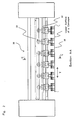
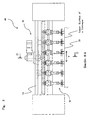
- Fig. 6 shows cross-section D-D of the laying-out and rotating apparatus 40 shown in Fig. 3 .
- Fig. 7 shows mainly a plain view of a laying-out mechanism 41 of the laying-out and rotating apparatus 40 (indicated by arrow E shown in Fig. 6 ), and an elevational view of the whole apparatus (indicated by arrow F shown in Fig. 6 ).
- the laying-out and rotating apparatus 40 is disposed at the downstream side of the separating apparatus 30 and above the downstream conveyer 20.
- the laying-out and rotating apparatus 40 is comprised of
- the laying-out and rotating apparatus 40 has the same number of the rotating mechanisms 42 as that of the pieces of food dough 2 in each row (each of the rows "a,” "b,”...) conveyed by the conveyers.
- a plurality of the rotating mechanisms 42 are connected to the node points of the pantograph type mechanism 41-2.
- a main structure 41-1 of the laying-out mechanism 41 is fixed to two supporting beams 43 to support whole of the laying-out and rotating apparatus 40, and is disposed at the center of the downstream conveyer 20 in the perpendicular direction.
- a driving motor 41-3 such as a servomotor, is fixed on the main structure 41-1 of the laying-out mechanism 41.
- a rotating shaft 41-4 of the driving motor 41-3 is rotatably supported by the main structure 41-1 by means of a bearing, and downwardly extends inside the main structure 41-1.
- a pinion gear 41-5 is fixed to the rotating shaft 41-4 of the driving motor 41-3.
- a first holding member 41-8 extending downwardly is disposed at the left end of the first rack gear 41-6 (the rack gear shown in the upper side of the plain view of Fig. 7 ), and a second holding member 41-9 extending downwardly is disposed at the right end of the second rack gear 41-7 (the rack gear shown in the lower side of the plain view of Fig. 7 ).
- a guide plate 41-10 is disposed under the main structure 41-1 and the two supporting beams 43, and at the position above the centerline of the downstream conveyer 20 extending in the conveying direction (see Fig. 7 ), and is fixed to the lower surfaces of the two supporting beams 43.
- Slotted through holes 41-11 extending in the conveying direction are disposed near the both ends of the guide plate 41-10.
- the guide plate 41-10 is placed so that the centerline of the slotted through holes 41-11 corresponds to the centerline extending in the conveying direction of the downstream conveyer 20.
- the pantograph type mechanism 41-2 used for the laying-out mechanism 41 has the configuration shown in Fig. 7 , and is comprised of links and node points.
- the numbers of the node points in rows "p" and "q" are five, respectively, and the number of the node points in the central row is six.
- the mechanism is not limited to that configuration. The number of the node points in each row may be increased or decreased.
- the first and second holding members 41-8 and 41-9 are fixed to the protruded members located in the central row of the pantograph type mechanism 41-2, and located at the second node points from the left and right ends toward the center of the central row.
- first and second holding members 41-8 and 41-9 are not limited to that configuration.
- first and second holding members 41-8 and 41-9 can be located with a predetermined interval in the perpendicular direction to the conveying direction of the pieces of food dough 2, the first and second holding members 41-8 and 41-9 may be fixed to other node points in the central row of the pantograph type mechanism 41-2, or fixed to other node points in the row "p" or "q" of the pantograph type mechanism 41-2.
- Protruded shafts 41-12 extending upwardly are rotatably inserted into the two node points that are located on the rows "p" and “q” and on the centerline (see Fig. 7 ) of the pantograph type mechanism 41-2 shown in Fig. 7 .
- the two protruded shafts 41-12 are slidably inserted into the slotted through holes 41-11 so as to slide along the longitudinal direction of the slotted through holes 41-11 disposed near the both ends of the guide plate 41-10 explained above.
- pantograph type mechanism 41-2 expands and contracts symmetrically on either side of the centerline extending in the conveying direction of the downstream conveyer 20.
- the mechanism using racks and a pinion is explained as a driving mechanism for expanding and contracting the pantograph type mechanism 41-2.
- the driving mechanism is not limited to that configuration.
- a cylinder device using a pressurized fluid or a linear actuator, etc., may also be used for the driving mechanism to expand and contract the pantograph type mechanism 41-2.
- the three rotating mechanisms 42 can be expands and contracted in the perpendicular direction (transverse direction), not by disposing a plurality of the driving mechanisms at a plurality of the node points, but by disposing one driving mechanism at only one node point.
- the rotating mechanisms 42 are disposed at holes at the node points in the central row of the pantograph type mechanism 41-2. (In this embodiment, 6 sets of the rotating mechanisms 42 are disposed.)
- the rotating mechanism 42 is comprised of
- linear moving mechanism 42-7 a linear motion mechanism using a ball bearing, which is known and described as a linear motion guide, may be used.
- the rotating shaft 42-3 of the rotating mechanism 42 has a plurality of the pins 42-1 at its lower end, and extends upwardly through the elongate through hole of the cylindrical structure 42-2.
- the rotating shaft 42-3 extending upwardly from the upper end of the cylindrical structure 42-2 passes inside the rotational driving mechanism 42-5 and through the supporting plate 42-4, and further extends upwardly, wherein the rotating shaft 42-3 can freely rotate and move up and down.
- the upper end of the rotating shaft 42-3 is fixed to the moving up-and-down beam 42-6.
- a power source such as a rotary actuator, may be used.
- a pushing plate 42-8 having a plurality of holes is fixed to the lower end of the cylindrical structure 42-2.
- a plurality of the pins 42-1 disposed at the lower end of the rotating shaft 42-3 pass through a plurality of holes of the pushing plate 42-8, and protrude downwardly.
- the upper end of the cylindrical structure 42-2 is fixed to the distal side of the supporting plate 42-4 by means of the rotational driving mechanism 42-5.
- a connecting shaft 42-9 is disposed at the proximal side (downstream side in the conveying direction) of the supporting plate 42-4, and protrudes upwardly.
- the upper end of the connecting shaft 42-9 is rotatably connected to the hole disposed at the node point in the central row of the pantograph type mechanism 41-2.
- the two linear moving mechanisms 42-7 extending in the perpendicular direction across the width of the downstream conveyer 20 are disposed under the supporting plate 42-4.
- the supporting plate 42-4 is fixed to the two linear moving mechanisms 42-7.
- the direction of the supporting plate 42-4 is maintained so that the longitudinal direction of it always becomes parallel to the conveying direction, and the supporting plate 42-4 moves in the perpendicular direction.
- the detecting device 60 detects a row of a plurality of the pieces of food dough 2, wherein the row is translocated from the upstream conveyer 10 to the downstream conveyer 20 by the separating apparatus 30, is positioned with a predetermined interval between the rows in the conveying direction, and is conveyed on the downstream conveyer 20, the moving up-and-down beam 42-6 begins to move down by the moving up and down mechanism (not shown).
- the rotating shaft 41-4 is rotated by the driving motor 41-3 of the laying-out mechanism 41.
- the pinion gear 41-5 fixed to the rotating shaft 41-4 is rotated, then the first holding member 41-8 disposed at the first rack gear 41-6 and the second holding member 41-9 disposed at the second rack gear 41-7 move in the perpendicular direction so as to get away from each other.
- first and second holding members 41-8 and 41-9 are fixed to the protruded shafts extending upwardly from the node points disposed at the left and right side in the central row of the pantograph type mechanism 41-2, when the first and second holding members 41-8 and 41-9 move in the perpendicular direction so as to get away from each other, the pantograph type mechanism 41-2 expands in the perpendicular direction.
- pantograph type mechanism 41-2 expands and contracts symmetrically at both sides of the centerline of the downstream conveyer 20 extending in the conveying direction.
- the rotating mechanism 42 is connected to each node point in the central row of the pantograph type mechanism 41-2, through the connecting shafts 42-9.
- the supporting plate 42-4 is fixed to the lower end of the connecting shaft 42-9
- the cylindrical structure 42-2 is fixed to the distal side of the supporting plate 42-4 by means of the rotational driving mechanism 42-5
- the rotating shaft 42-3 of the rotating mechanism 42 is disposed at the distal side of the supporting plate 42-4 through the inside of the cylindrical structure 42-2, and the rotating shaft 42-3 can freely rotate and move up and down.
- the rotating shaft 42-3 is rotated by the rotational driving mechanism 42-5, and the piece of food dough 2 is rotated in a predetermined rotational direction and at a predetermined angle.
- the rotational direction and angle of the piece of the food dough 2 are determined depending on the shape and the direction of the piece 2 that is conveyed by the upstream conveyer 10.
- the pieces of food dough 2 separated from a plurality of the pins 42-1 are positioned with a predetermined intervals in the conveying direction and the perpendicular direction, and are conveyed so that the specific base 2-2 of the triangular shape of each of the pieces 2 is located at the downstream side in the conveying direction and the specific apex 2-1 of it faces toward the upstream side in the conveying direction.
- the pantograph type mechanism 41-2 can be expanded and contracted in an arbitrary dimension, the intervals of the pieces 2 laid out in the perpendicular direction can be set in an arbitrary dimension.
- the rotating mechanisms 42 are disposed at holes disposed at the node points in the central row of the pantograph type mechanism 41-2.
- rotating mechanisms 42 are disposed at every node point in the central row.
- the rotating mechanisms 42 may not be disposed at any node points in the central row.
- the positioning of a plurality of the pins 42-1 disposed at the lower end of the rotating shaft 42-3 is not limited to a specific configuration.
- the pins 42-1 may be positioned on a circle with equal intervals.
- the pins 42-1 must be positioned so that at least two pins of them always stick the piece 2.
- Fig. 8 shows a view of cross-section G-G shown in Fig. 1 , and shows a side elevational view of the shutter apparatus 50.
- the shutter apparatus 50 is disposed at the downstream side of the laying-out and rotating apparatus 40.
- the shutter apparatus 50 aligns the pieces of food dough 2 set in a line, wherein the pieces 2 are positioned with predetermined intervals in the conveying and perpendicular directions, and are faced toward a predetermined direction by the laying-out and rotating apparatus 40 so that specific bases 2-2 of the pieces of food dough 2 having a triangular shape are set in a line in the perpendicular direction.
- the shutter apparatus 50 is comprised of:
- the rotating shaft 51 When the rotating shaft 51 is rotated clockwise at a predetermined angle (in the inverse direction of the arrow indicating a rotational direction in Fig. 8 ) by the rotational driving means (not shown), the shutter plates 53 face toward the horizontal direction, and the distal ends of the shutter plates 53 come to the upper surface of the downstream conveyer 20.
- the shutter plates 53 face toward the horizontal direction, and the distal ends of the shutter plates 53 come to the upper surface of the downstream conveyer 20.
- the pieces of food dough 2 are conveyed on the downstream conveyer 20 so that the specific bases 2-2 of the triangular shapes are positioned at the downstream side in the conveying direction, and are parallel to the perpendicular direction, wherein the specific apexes 2-1 of the triangular shapes face toward the upstream side in the conveying direction.
- the specific bases 2-2 of the pieces 2 having a triangular shape reach the plates 53, and are aligned in a line so that the specific bases 2-2 are parallel to the perpendicular direction to the conveying direction.
- the rotating shaft 51 is rotated counterclockwise at a predetermined angle, and the distal ends of the shutter plates 53 move up to enough heights from the upper surface of the downstream conveyer 20 so that the plates 53 do not contact with the pieces 2, while the plates 53 are inclining.
- the shutter apparatus 50 Since the shutter apparatus 50 is driven in synchronization with the movement of the laying-out and rotating apparatus 40 and the downstream conveyer 20, the shutter apparatus 50 is driven corresponding to the condition of the conveyance of the pieces 2.
- Fig. 9 is a set of explanatory drawings to explain a method for detecting the pieces of food dough 2 by the detecting device 60, which shows the relationships of the positions of sensors 61 of the detecting device 60 and the pieces 2.
- the detecting device 60 is disposed between the separating apparatus 30 and the laying-out and rotating apparatus 40 (namely, at the downstream side of the separating apparatus 30 and at the upstream side of the laying-out and rotating apparatus 40), and above the downstream conveyer 20 (see Fig. 5 ).
- the laying-out and rotating apparatus 40 is driven according to signals detected by the detecting device 60.
- the detecting device 60 is comprised of a sensor(s) 61 and a mounting bracket 62.
- the sensor(s) 61 is mounted to one end of the mounting bracket 62, and the other end of the mounting bracket 62 is connected to the fixed structure.
- the sensor(s) 61 at least one or two optical sensors may be used, or at least one image sensor may be used.
- the optical sensor can detect the time when points "a” and "b” of the piece of food dough 2 having a triangular shape that is conveyed on the downstream conveyer 20 pass the position of the sensor "A.”
- a position of a point "c" located on the median line of the piece 2 having the triangular shape can be calculated based on the speed of the downstream conveyer 20 and the time when the points "a” and "b” pass the position of the sensor "A.”
- the laying-out and rotating apparatus 40 can be controlled so that the center of a plurality of the pins 42-1 of the laying-out and rotating apparatus 40 coincides with a position on the median line of the piece 2 having a triangular shape. Consequently, an accuracy of the positioning of the center of the piece of food dough 2 that is aligned and positioned can be improved dramatically.
- the optical sensors can detect the time when points "a” and “b” of the piece of food dough 2 having a triangular shape that is conveyed on the downstream conveyer 20 pass the position of the sensor "A,” and the time when points “c” and “d” of the piece 2 pass the position of the sensor "B.”
- the widths of the piece 2 can be calculated by comparing the time when the points "a” and “b” pass the position of the sensor "A” and the time when the points "c” and “d” pass the position of the sensor "B.” Consequently, the direction of the piece 2 can be identified.
- the laying-out and rotating apparatus 40 can be controlled so that the center of a plurality of the pins 42-1 of the laying-out and rotating apparatus 40 coincides with the position on the median line of the piece of food dough 2 having a triangular shape. Furthermore, the movement of the laying-out and rotating apparatus 40 can be controlled by determining the rotational direction of the piece 2 having a triangular shape that is conveyed.
- the pieces 2 can be aligned and positioned with regularity so that the pieces 2 are positioned toward a predetermined direction.
- the positions of the median lines and the directions, of the pieces of food dough 2 having a triangular shape that are conveyed can be detected.
- the same effects as those in a case where the two optical sensors are disposed can be achieved.
- the pieces 2 can be rotated so that the median lines of the pieces 2 are parallel to the conveying direction by controlling the movement of the laying-out and rotating apparatus 40.
Landscapes
- Engineering & Computer Science (AREA)
- Life Sciences & Earth Sciences (AREA)
- Food Science & Technology (AREA)
- Mechanical Engineering (AREA)
- Manufacturing And Processing Devices For Dough (AREA)
- Specific Conveyance Elements (AREA)
- Attitude Control For Articles On Conveyors (AREA)
Applications Claiming Priority (1)
| Application Number | Priority Date | Filing Date | Title |
|---|---|---|---|
| JP2014022332A JP6121344B2 (ja) | 2014-02-07 | 2014-02-07 | 食品生地切断片の整列配置装置 |
Publications (4)
| Publication Number | Publication Date |
|---|---|
| EP2904905A2 true EP2904905A2 (fr) | 2015-08-12 |
| EP2904905A3 EP2904905A3 (fr) | 2015-09-02 |
| EP2904905B1 EP2904905B1 (fr) | 2019-05-08 |
| EP2904905B8 EP2904905B8 (fr) | 2019-06-26 |
Family
ID=52394082
Family Applications (1)
| Application Number | Title | Priority Date | Filing Date |
|---|---|---|---|
| EP15000158.4A Active EP2904905B8 (fr) | 2014-02-07 | 2015-01-21 | Appareil permettant d'aligner et de positionner des morceaux de pâte alimentaire |
Country Status (4)
| Country | Link |
|---|---|
| US (1) | US9408398B2 (fr) |
| EP (1) | EP2904905B8 (fr) |
| JP (1) | JP6121344B2 (fr) |
| ES (1) | ES2732187T3 (fr) |
Cited By (4)
| Publication number | Priority date | Publication date | Assignee | Title |
|---|---|---|---|---|
| CN105746626A (zh) * | 2016-04-29 | 2016-07-13 | 北京申晨机械设备有限公司 | 面片分离机构、面片转向运输装置及面片裁切设备 |
| CN109497115A (zh) * | 2018-12-06 | 2019-03-22 | 北京申晨机械设备有限公司 | 一种面片挡正装置和搓卷面包生产线 |
| CN113545635A (zh) * | 2021-08-18 | 2021-10-26 | 深圳众凡达科技有限公司 | 一种电子产品销售展示架 |
| CN115644203A (zh) * | 2022-10-14 | 2023-01-31 | 龙海市安得马富机械有限公司 | 一种牛角面包面皮自动化制作系统 |
Families Citing this family (12)
| Publication number | Priority date | Publication date | Assignee | Title |
|---|---|---|---|---|
| DE102014005998B3 (de) * | 2014-04-28 | 2015-05-13 | Fritsch Gmbh | Verfahren und Vorrichtung zur Erzeugung von Zuschnitten von Teigstücken aus einer oder mehreren Teigbahnen |
| JP6505548B2 (ja) * | 2015-08-26 | 2019-04-24 | プリマハム株式会社 | 整列補助装置 |
| CN106142392B (zh) * | 2016-08-16 | 2019-01-18 | 昆山倚天自动化科技股份有限公司 | 一种注塑成型产品的定向上料装置 |
| EP3315029B1 (fr) | 2016-10-31 | 2019-09-11 | Rheon Automatic Machinery Co. Ltd. | Appareil d'alignement et de positionnement de morceaux de pâte alimentaire |
| CN107244449B (zh) * | 2017-06-22 | 2022-10-11 | 山东钢铁股份有限公司 | 一种齐头挡板装置 |
| CN109769880B (zh) * | 2019-03-26 | 2024-06-04 | 北京申晨机械设备有限公司 | 面片切割分离装置、面包生产设备及面片切割分离方法 |
| JP7184363B2 (ja) * | 2019-12-24 | 2022-12-06 | 株式会社フジキカイ | 物品集積移載装置 |
| JP7342064B2 (ja) * | 2021-05-31 | 2023-09-11 | レオン自動機株式会社 | 食品生地片の移載方法及び移載装置 |
| CN113911626B (zh) * | 2021-11-17 | 2025-09-12 | 成都康河机械设备有限公司 | 南瓜饼成型机 |
| TWI871004B (zh) * | 2022-09-14 | 2025-01-21 | 日商雷恩自動機股份有限公司 | 麵糰片排列方法 |
| NL2035961B1 (en) * | 2023-10-05 | 2025-04-11 | Radie Bv | Device and method for spacing dough pieces |
| KR102882288B1 (ko) * | 2025-01-06 | 2025-11-05 | 씨제이푸드빌 주식회사 | 카스테라 커버필름 공급장치 |
Citations (1)
| Publication number | Priority date | Publication date | Assignee | Title |
|---|---|---|---|---|
| JPH0361883U (fr) | 1989-10-19 | 1991-06-18 |
Family Cites Families (16)
| Publication number | Priority date | Publication date | Assignee | Title |
|---|---|---|---|---|
| IT1100425B (it) * | 1978-11-29 | 1985-09-28 | Costa Maurizio Dalla | Macchina atta ad effettuare il taglio in triangoli di pasta sfogliata a la successiva presa rotazione e distanziamento dei triangoli stessi,per la formatura di croissants brioches e simili |
| JPH0344114U (fr) * | 1989-09-08 | 1991-04-24 | ||
| JP2567296B2 (ja) * | 1990-10-23 | 1996-12-25 | レオン自動機 株式会社 | クロワッサン生地片の拡開、方向変換方法及び装置 |
| JP2747755B2 (ja) * | 1992-04-27 | 1998-05-06 | レオン自動機株式会社 | 円柱状生地の調心方法 |
| JP2733810B2 (ja) * | 1992-07-22 | 1998-03-30 | レオン自動機株式会社 | フィリング充填装置 |
| IT1268941B1 (it) * | 1994-02-04 | 1997-03-18 | C I M Srl | Macchina per la produzione di croissants |
| JP3111021B2 (ja) * | 1996-04-17 | 2000-11-20 | レオン自動機株式会社 | 整列搬送装置 |
| JP3009132B2 (ja) * | 1996-12-04 | 2000-02-14 | レオン自動機株式会社 | 食品生地の搬送方法、及び食品生地搬送機 |
| JP3463172B2 (ja) * | 1997-04-18 | 2003-11-05 | アー フリッチュ ゲーエムベーハー ウント コンパニー コマンディト ゲゼルシャフト | 連続的な生地搬送路から個々の生地片を分離する装置 |
| JP5073952B2 (ja) * | 2006-02-16 | 2012-11-14 | レオン自動機株式会社 | 生地片拡開装置 |
| JP4919339B2 (ja) * | 2006-11-10 | 2012-04-18 | レオン自動機株式会社 | 食品生地の切断方法及びその装置 |
| ITVR20090113A1 (it) * | 2009-07-24 | 2011-01-25 | Rondo Schio S R L | Dispositivo di distanziamento e di allineamento, particolarmente per linee di produzione e di trattamento di prodotti alimentari arrotolati |
| JP5647777B2 (ja) * | 2009-08-11 | 2015-01-07 | レオン自動機株式会社 | 食品生地切断片旋回装置 |
| JP2011193815A (ja) * | 2010-03-19 | 2011-10-06 | Rheon Automatic Machinerty Co Ltd | シート状食品生地の折り畳み装置及び方法 |
| JP5466989B2 (ja) * | 2010-04-28 | 2014-04-09 | レオン自動機株式会社 | 食品生地の整列方法及び装置 |
| US9307772B2 (en) * | 2011-06-02 | 2016-04-12 | Rheon Automatic Machinery Co., Ltd. | Method and an apparatus for forming a food product into a circular shape |
-
2014
- 2014-02-07 JP JP2014022332A patent/JP6121344B2/ja active Active
-
2015
- 2015-01-21 ES ES15000158T patent/ES2732187T3/es active Active
- 2015-01-21 EP EP15000158.4A patent/EP2904905B8/fr active Active
- 2015-02-06 US US14/615,707 patent/US9408398B2/en active Active
Patent Citations (1)
| Publication number | Priority date | Publication date | Assignee | Title |
|---|---|---|---|---|
| JPH0361883U (fr) | 1989-10-19 | 1991-06-18 |
Cited By (6)
| Publication number | Priority date | Publication date | Assignee | Title |
|---|---|---|---|---|
| CN105746626A (zh) * | 2016-04-29 | 2016-07-13 | 北京申晨机械设备有限公司 | 面片分离机构、面片转向运输装置及面片裁切设备 |
| CN109497115A (zh) * | 2018-12-06 | 2019-03-22 | 北京申晨机械设备有限公司 | 一种面片挡正装置和搓卷面包生产线 |
| CN109497115B (zh) * | 2018-12-06 | 2023-09-29 | 北京申晨机械设备有限公司 | 一种面片挡正装置和搓卷面包生产线 |
| CN113545635A (zh) * | 2021-08-18 | 2021-10-26 | 深圳众凡达科技有限公司 | 一种电子产品销售展示架 |
| CN115644203A (zh) * | 2022-10-14 | 2023-01-31 | 龙海市安得马富机械有限公司 | 一种牛角面包面皮自动化制作系统 |
| CN115644203B (zh) * | 2022-10-14 | 2024-03-29 | 龙海市安得马富机械有限公司 | 一种牛角面包面皮自动化制作系统 |
Also Published As
| Publication number | Publication date |
|---|---|
| JP6121344B2 (ja) | 2017-04-26 |
| US20150223474A1 (en) | 2015-08-13 |
| EP2904905A3 (fr) | 2015-09-02 |
| ES2732187T3 (es) | 2019-11-21 |
| EP2904905B8 (fr) | 2019-06-26 |
| EP2904905B1 (fr) | 2019-05-08 |
| US9408398B2 (en) | 2016-08-09 |
| JP2015146781A (ja) | 2015-08-20 |
Similar Documents
| Publication | Publication Date | Title |
|---|---|---|
| EP2904905A2 (fr) | Appareil permettant d'aligner et de positionner des morceaux de pâte alimentaire | |
| US6044778A (en) | Method and device for picking up seedlings from seedling tray | |
| JP3872549B2 (ja) | ピックアップ装置 | |
| SE1001228A1 (sv) | Rullformningsmaskin och sätt att rullforma ett plant ämne med variabel bredd | |
| US8714078B2 (en) | Apparatus for spacing and aligning pieces of food dough | |
| CN104378990A (zh) | 具有可侧向移位的输送带的烤炉转移装置 | |
| EP3388374B1 (fr) | Technologie de chute de lots par batch | |
| US10775224B2 (en) | Weighing systems, methods, and installations for weighing selected products transported in multiple lanes and/or sequentally | |
| US9415948B1 (en) | Method for stabilizing bottles for pattern forming and related device | |
| US8327998B2 (en) | Method and an apparatus for aligning pieces of food dough | |
| MXPA05009224A (es) | Sistema de agrupamiento automatico de barras de masa y/o cualquier producto panadero crudo o cocido. | |
| EP2716159B1 (fr) | Un procédé et un dispositif pour la formation d'un produit alimentaire circulaire. | |
| CN108688873A (zh) | 一种罐体装箱装置及自动装箱方法 | |
| EP0670114A1 (fr) | Appareil pour la production de croissants | |
| EP3574761B1 (fr) | Dispositif, ainsi que procédé pour tourner alternativement des produits de cuisson plats | |
| EP2668124B1 (fr) | Transporteur annulaire | |
| EP2108263B1 (fr) | Installation de transport pour les lignes de moulage de produits de confiserie, particulièrement de chocolat | |
| JP6908269B2 (ja) | 山形鋼の段積装置 | |
| DE102019210959A1 (de) | Wiegevorrichtung und Verfahren zum Wiegen einer Lebensmittelportion auf Auflageelementen | |
| ES2256227T3 (es) | Dispositivo de pala para cargar y transferir laminas de masa, particularmente para pizzas. | |
| JP7129785B2 (ja) | 切れ目形成装置、および切れ目の形成方法 | |
| EP4533952A1 (fr) | Dispositif et procédé pour séparer des morceaux de pâte | |
| CN214326331U (zh) | 一种型钢计数定位机构 | |
| EP4265544B1 (fr) | Système de transport en bout de ligne et procédé de transport et de collecte d'un ou de plusieurs produits au moyen dudit système de transport en bout de ligne | |
| CN100488348C (zh) | 一种元件定位装置 |
Legal Events
| Date | Code | Title | Description |
|---|---|---|---|
| PUAL | Search report despatched |
Free format text: ORIGINAL CODE: 0009013 |
|
| PUAI | Public reference made under article 153(3) epc to a published international application that has entered the european phase |
Free format text: ORIGINAL CODE: 0009012 |
|
| AK | Designated contracting states |
Kind code of ref document: A2 Designated state(s): AL AT BE BG CH CY CZ DE DK EE ES FI FR GB GR HR HU IE IS IT LI LT LU LV MC MK MT NL NO PL PT RO RS SE SI SK SM TR |
|
| AX | Request for extension of the european patent |
Extension state: BA ME |
|
| AK | Designated contracting states |
Kind code of ref document: A3 Designated state(s): AL AT BE BG CH CY CZ DE DK EE ES FI FR GB GR HR HU IE IS IT LI LT LU LV MC MK MT NL NO PL PT RO RS SE SI SK SM TR |
|
| AX | Request for extension of the european patent |
Extension state: BA ME |
|
| RIC1 | Information provided on ipc code assigned before grant |
Ipc: A21C 9/08 20060101AFI20150728BHEP Ipc: A21C 11/10 20060101ALI20150728BHEP |
|
| 17P | Request for examination filed |
Effective date: 20160114 |
|
| RBV | Designated contracting states (corrected) |
Designated state(s): AL AT BE BG CH CY CZ DE DK EE ES FI FR GB GR HR HU IE IS IT LI LT LU LV MC MK MT NL NO PL PT RO RS SE SI SK SM TR |
|
| STAA | Information on the status of an ep patent application or granted ep patent |
Free format text: STATUS: EXAMINATION IS IN PROGRESS |
|
| 17Q | First examination report despatched |
Effective date: 20170309 |
|
| GRAJ | Information related to disapproval of communication of intention to grant by the applicant or resumption of examination proceedings by the epo deleted |
Free format text: ORIGINAL CODE: EPIDOSDIGR1 |
|
| GRAP | Despatch of communication of intention to grant a patent |
Free format text: ORIGINAL CODE: EPIDOSNIGR1 |
|
| GRAP | Despatch of communication of intention to grant a patent |
Free format text: ORIGINAL CODE: EPIDOSNIGR1 |
|
| STAA | Information on the status of an ep patent application or granted ep patent |
Free format text: STATUS: GRANT OF PATENT IS INTENDED |
|
| INTG | Intention to grant announced |
Effective date: 20181207 |
|
| GRAS | Grant fee paid |
Free format text: ORIGINAL CODE: EPIDOSNIGR3 |
|
| GRAA | (expected) grant |
Free format text: ORIGINAL CODE: 0009210 |
|
| STAA | Information on the status of an ep patent application or granted ep patent |
Free format text: STATUS: THE PATENT HAS BEEN GRANTED |
|
| GRAT | Correction requested after decision to grant or after decision to maintain patent in amended form |
Free format text: ORIGINAL CODE: EPIDOSNCDEC |
|
| AK | Designated contracting states |
Kind code of ref document: B1 Designated state(s): AL AT BE BG CH CY CZ DE DK EE ES FI FR GB GR HR HU IE IS IT LI LT LU LV MC MK MT NL NO PL PT RO RS SE SI SK SM TR |
|
| REG | Reference to a national code |
Ref country code: GB Ref legal event code: FG4D |
|
| REG | Reference to a national code |
Ref country code: CH Ref legal event code: EP Ref country code: AT Ref legal event code: REF Ref document number: 1128746 Country of ref document: AT Kind code of ref document: T Effective date: 20190515 |
|
| REG | Reference to a national code |
Ref country code: DE Ref legal event code: R096 Ref document number: 602015029602 Country of ref document: DE Ref country code: IE Ref legal event code: FG4D |
|
| REG | Reference to a national code |
Ref country code: CH Ref legal event code: PK Free format text: BERICHTIGUNG B8 |
|
| RAP2 | Party data changed (patent owner data changed or rights of a patent transferred) |
Owner name: RHEON AUTOMATIC MACHINERY CO., LTD. |
|
| REG | Reference to a national code |
Ref country code: CH Ref legal event code: NV Representative=s name: VALIPAT S.A. C/O BOVARD SA NEUCHATEL, CH |
|
| REG | Reference to a national code |
Ref country code: NL Ref legal event code: FP |
|
| REG | Reference to a national code |
Ref country code: LT Ref legal event code: MG4D |
|
| REG | Reference to a national code |
Ref country code: GR Ref legal event code: EP Ref document number: 20190401860 Country of ref document: GR Effective date: 20190906 |
|
| PG25 | Lapsed in a contracting state [announced via postgrant information from national office to epo] |
Ref country code: SE Free format text: LAPSE BECAUSE OF FAILURE TO SUBMIT A TRANSLATION OF THE DESCRIPTION OR TO PAY THE FEE WITHIN THE PRESCRIBED TIME-LIMIT Effective date: 20190508 Ref country code: HR Free format text: LAPSE BECAUSE OF FAILURE TO SUBMIT A TRANSLATION OF THE DESCRIPTION OR TO PAY THE FEE WITHIN THE PRESCRIBED TIME-LIMIT Effective date: 20190508 Ref country code: PT Free format text: LAPSE BECAUSE OF FAILURE TO SUBMIT A TRANSLATION OF THE DESCRIPTION OR TO PAY THE FEE WITHIN THE PRESCRIBED TIME-LIMIT Effective date: 20190908 Ref country code: AL Free format text: LAPSE BECAUSE OF FAILURE TO SUBMIT A TRANSLATION OF THE DESCRIPTION OR TO PAY THE FEE WITHIN THE PRESCRIBED TIME-LIMIT Effective date: 20190508 Ref country code: NO Free format text: LAPSE BECAUSE OF FAILURE TO SUBMIT A TRANSLATION OF THE DESCRIPTION OR TO PAY THE FEE WITHIN THE PRESCRIBED TIME-LIMIT Effective date: 20190808 Ref country code: FI Free format text: LAPSE BECAUSE OF FAILURE TO SUBMIT A TRANSLATION OF THE DESCRIPTION OR TO PAY THE FEE WITHIN THE PRESCRIBED TIME-LIMIT Effective date: 20190508 Ref country code: LT Free format text: LAPSE BECAUSE OF FAILURE TO SUBMIT A TRANSLATION OF THE DESCRIPTION OR TO PAY THE FEE WITHIN THE PRESCRIBED TIME-LIMIT Effective date: 20190508 |
|
| REG | Reference to a national code |
Ref country code: ES Ref legal event code: FG2A Ref document number: 2732187 Country of ref document: ES Kind code of ref document: T3 Effective date: 20191121 |
|
| PG25 | Lapsed in a contracting state [announced via postgrant information from national office to epo] |
Ref country code: BG Free format text: LAPSE BECAUSE OF FAILURE TO SUBMIT A TRANSLATION OF THE DESCRIPTION OR TO PAY THE FEE WITHIN THE PRESCRIBED TIME-LIMIT Effective date: 20190808 Ref country code: RS Free format text: LAPSE BECAUSE OF FAILURE TO SUBMIT A TRANSLATION OF THE DESCRIPTION OR TO PAY THE FEE WITHIN THE PRESCRIBED TIME-LIMIT Effective date: 20190508 Ref country code: LV Free format text: LAPSE BECAUSE OF FAILURE TO SUBMIT A TRANSLATION OF THE DESCRIPTION OR TO PAY THE FEE WITHIN THE PRESCRIBED TIME-LIMIT Effective date: 20190508 |
|
| PG25 | Lapsed in a contracting state [announced via postgrant information from national office to epo] |
Ref country code: EE Free format text: LAPSE BECAUSE OF FAILURE TO SUBMIT A TRANSLATION OF THE DESCRIPTION OR TO PAY THE FEE WITHIN THE PRESCRIBED TIME-LIMIT Effective date: 20190508 Ref country code: DK Free format text: LAPSE BECAUSE OF FAILURE TO SUBMIT A TRANSLATION OF THE DESCRIPTION OR TO PAY THE FEE WITHIN THE PRESCRIBED TIME-LIMIT Effective date: 20190508 Ref country code: CZ Free format text: LAPSE BECAUSE OF FAILURE TO SUBMIT A TRANSLATION OF THE DESCRIPTION OR TO PAY THE FEE WITHIN THE PRESCRIBED TIME-LIMIT Effective date: 20190508 Ref country code: SK Free format text: LAPSE BECAUSE OF FAILURE TO SUBMIT A TRANSLATION OF THE DESCRIPTION OR TO PAY THE FEE WITHIN THE PRESCRIBED TIME-LIMIT Effective date: 20190508 Ref country code: RO Free format text: LAPSE BECAUSE OF FAILURE TO SUBMIT A TRANSLATION OF THE DESCRIPTION OR TO PAY THE FEE WITHIN THE PRESCRIBED TIME-LIMIT Effective date: 20190508 |
|
| REG | Reference to a national code |
Ref country code: DE Ref legal event code: R097 Ref document number: 602015029602 Country of ref document: DE |
|
| PG25 | Lapsed in a contracting state [announced via postgrant information from national office to epo] |
Ref country code: SM Free format text: LAPSE BECAUSE OF FAILURE TO SUBMIT A TRANSLATION OF THE DESCRIPTION OR TO PAY THE FEE WITHIN THE PRESCRIBED TIME-LIMIT Effective date: 20190508 |
|
| PLBE | No opposition filed within time limit |
Free format text: ORIGINAL CODE: 0009261 |
|
| STAA | Information on the status of an ep patent application or granted ep patent |
Free format text: STATUS: NO OPPOSITION FILED WITHIN TIME LIMIT |
|
| PG25 | Lapsed in a contracting state [announced via postgrant information from national office to epo] |
Ref country code: TR Free format text: LAPSE BECAUSE OF FAILURE TO SUBMIT A TRANSLATION OF THE DESCRIPTION OR TO PAY THE FEE WITHIN THE PRESCRIBED TIME-LIMIT Effective date: 20190508 |
|
| 26N | No opposition filed |
Effective date: 20200211 |
|
| PG25 | Lapsed in a contracting state [announced via postgrant information from national office to epo] |
Ref country code: PL Free format text: LAPSE BECAUSE OF FAILURE TO SUBMIT A TRANSLATION OF THE DESCRIPTION OR TO PAY THE FEE WITHIN THE PRESCRIBED TIME-LIMIT Effective date: 20190508 |
|
| PG25 | Lapsed in a contracting state [announced via postgrant information from national office to epo] |
Ref country code: SI Free format text: LAPSE BECAUSE OF FAILURE TO SUBMIT A TRANSLATION OF THE DESCRIPTION OR TO PAY THE FEE WITHIN THE PRESCRIBED TIME-LIMIT Effective date: 20190508 |
|
| PG25 | Lapsed in a contracting state [announced via postgrant information from national office to epo] |
Ref country code: MC Free format text: LAPSE BECAUSE OF FAILURE TO SUBMIT A TRANSLATION OF THE DESCRIPTION OR TO PAY THE FEE WITHIN THE PRESCRIBED TIME-LIMIT Effective date: 20190508 |
|
| GBPC | Gb: european patent ceased through non-payment of renewal fee |
Effective date: 20200121 |
|
| REG | Reference to a national code |
Ref country code: BE Ref legal event code: MM Effective date: 20200131 |
|
| PG25 | Lapsed in a contracting state [announced via postgrant information from national office to epo] |
Ref country code: LU Free format text: LAPSE BECAUSE OF NON-PAYMENT OF DUE FEES Effective date: 20200121 Ref country code: GB Free format text: LAPSE BECAUSE OF NON-PAYMENT OF DUE FEES Effective date: 20200121 |
|
| PG25 | Lapsed in a contracting state [announced via postgrant information from national office to epo] |
Ref country code: BE Free format text: LAPSE BECAUSE OF NON-PAYMENT OF DUE FEES Effective date: 20200131 |
|
| PG25 | Lapsed in a contracting state [announced via postgrant information from national office to epo] |
Ref country code: IE Free format text: LAPSE BECAUSE OF NON-PAYMENT OF DUE FEES Effective date: 20200121 |
|
| REG | Reference to a national code |
Ref country code: AT Ref legal event code: UEP Ref document number: 1128746 Country of ref document: AT Kind code of ref document: T Effective date: 20190508 |
|
| PG25 | Lapsed in a contracting state [announced via postgrant information from national office to epo] |
Ref country code: MT Free format text: LAPSE BECAUSE OF FAILURE TO SUBMIT A TRANSLATION OF THE DESCRIPTION OR TO PAY THE FEE WITHIN THE PRESCRIBED TIME-LIMIT Effective date: 20190508 Ref country code: CY Free format text: LAPSE BECAUSE OF FAILURE TO SUBMIT A TRANSLATION OF THE DESCRIPTION OR TO PAY THE FEE WITHIN THE PRESCRIBED TIME-LIMIT Effective date: 20190508 |
|
| PG25 | Lapsed in a contracting state [announced via postgrant information from national office to epo] |
Ref country code: MK Free format text: LAPSE BECAUSE OF FAILURE TO SUBMIT A TRANSLATION OF THE DESCRIPTION OR TO PAY THE FEE WITHIN THE PRESCRIBED TIME-LIMIT Effective date: 20190508 Ref country code: IS Free format text: LAPSE BECAUSE OF FAILURE TO SUBMIT A TRANSLATION OF THE DESCRIPTION OR TO PAY THE FEE WITHIN THE PRESCRIBED TIME-LIMIT Effective date: 20190908 |
|
| P01 | Opt-out of the competence of the unified patent court (upc) registered |
Effective date: 20230626 |
|
| REG | Reference to a national code |
Ref country code: CH Ref legal event code: U11 Free format text: ST27 STATUS EVENT CODE: U-0-0-U10-U11 (AS PROVIDED BY THE NATIONAL OFFICE) Effective date: 20260201 |
|
| PGFP | Annual fee paid to national office [announced via postgrant information from national office to epo] |
Ref country code: NL Payment date: 20260121 Year of fee payment: 12 |
|
| PGFP | Annual fee paid to national office [announced via postgrant information from national office to epo] |
Ref country code: ES Payment date: 20260227 Year of fee payment: 12 |
|
| PGFP | Annual fee paid to national office [announced via postgrant information from national office to epo] |
Ref country code: DE Payment date: 20260121 Year of fee payment: 12 |
|
| PGFP | Annual fee paid to national office [announced via postgrant information from national office to epo] |
Ref country code: AT Payment date: 20260122 Year of fee payment: 12 |
|
| PGFP | Annual fee paid to national office [announced via postgrant information from national office to epo] |
Ref country code: IT Payment date: 20260126 Year of fee payment: 12 |
|
| PGFP | Annual fee paid to national office [announced via postgrant information from national office to epo] |
Ref country code: FR Payment date: 20260123 Year of fee payment: 12 |
|
| PGFP | Annual fee paid to national office [announced via postgrant information from national office to epo] |
Ref country code: CH Payment date: 20260201 Year of fee payment: 12 |
|
| PGFP | Annual fee paid to national office [announced via postgrant information from national office to epo] |
Ref country code: GR Payment date: 20260122 Year of fee payment: 12 |