EP2907620B1 - Machine-outil dotée d'un bâti de machine composé d'éléments structuraux et méthode pour celle-ci - Google Patents
Machine-outil dotée d'un bâti de machine composé d'éléments structuraux et méthode pour celle-ci Download PDFInfo
- Publication number
- EP2907620B1 EP2907620B1 EP15155266.8A EP15155266A EP2907620B1 EP 2907620 B1 EP2907620 B1 EP 2907620B1 EP 15155266 A EP15155266 A EP 15155266A EP 2907620 B1 EP2907620 B1 EP 2907620B1
- Authority
- EP
- European Patent Office
- Prior art keywords
- machine tool
- components
- machine
- cooling
- channel system
- Prior art date
- Legal status (The legal status is an assumption and is not a legal conclusion. Google has not performed a legal analysis and makes no representation as to the accuracy of the status listed.)
- Active
Links
Images


Classifications
-
- B—PERFORMING OPERATIONS; TRANSPORTING
- B23—MACHINE TOOLS; METAL-WORKING NOT OTHERWISE PROVIDED FOR
- B23Q—DETAILS, COMPONENTS, OR ACCESSORIES FOR MACHINE TOOLS, e.g. ARRANGEMENTS FOR COPYING OR CONTROLLING; MACHINE TOOLS IN GENERAL CHARACTERISED BY THE CONSTRUCTION OF PARTICULAR DETAILS OR COMPONENTS; COMBINATIONS OR ASSOCIATIONS OF METAL-WORKING MACHINES, NOT DIRECTED TO A PARTICULAR RESULT
- B23Q11/00—Accessories fitted to machine tools for keeping tools or parts of the machine in good working condition or for cooling work; Safety devices specially combined with or arranged in, or specially adapted for use in connection with, machine tools
- B23Q11/12—Arrangements for cooling or lubricating parts of the machine
- B23Q11/126—Arrangements for cooling or lubricating parts of the machine for cooling only
- B23Q11/128—Arrangements for cooling or lubricating parts of the machine for cooling only for cooling frame parts
-
- B—PERFORMING OPERATIONS; TRANSPORTING
- B23—MACHINE TOOLS; METAL-WORKING NOT OTHERWISE PROVIDED FOR
- B23Q—DETAILS, COMPONENTS, OR ACCESSORIES FOR MACHINE TOOLS, e.g. ARRANGEMENTS FOR COPYING OR CONTROLLING; MACHINE TOOLS IN GENERAL CHARACTERISED BY THE CONSTRUCTION OF PARTICULAR DETAILS OR COMPONENTS; COMBINATIONS OR ASSOCIATIONS OF METAL-WORKING MACHINES, NOT DIRECTED TO A PARTICULAR RESULT
- B23Q11/00—Accessories fitted to machine tools for keeping tools or parts of the machine in good working condition or for cooling work; Safety devices specially combined with or arranged in, or specially adapted for use in connection with, machine tools
- B23Q11/14—Methods or arrangements for maintaining a constant temperature in parts of machine tools
- B23Q11/141—Methods or arrangements for maintaining a constant temperature in parts of machine tools using a closed fluid circuit for cooling or heating
-
- B—PERFORMING OPERATIONS; TRANSPORTING
- B23—MACHINE TOOLS; METAL-WORKING NOT OTHERWISE PROVIDED FOR
- B23Q—DETAILS, COMPONENTS, OR ACCESSORIES FOR MACHINE TOOLS, e.g. ARRANGEMENTS FOR COPYING OR CONTROLLING; MACHINE TOOLS IN GENERAL CHARACTERISED BY THE CONSTRUCTION OF PARTICULAR DETAILS OR COMPONENTS; COMBINATIONS OR ASSOCIATIONS OF METAL-WORKING MACHINES, NOT DIRECTED TO A PARTICULAR RESULT
- B23Q1/00—Members which are comprised in the general build-up of a form of machine, particularly relatively large fixed members
- B23Q1/01—Frames, beds, pillars or like members; Arrangement of ways
-
- B—PERFORMING OPERATIONS; TRANSPORTING
- B23—MACHINE TOOLS; METAL-WORKING NOT OTHERWISE PROVIDED FOR
- B23Q—DETAILS, COMPONENTS, OR ACCESSORIES FOR MACHINE TOOLS, e.g. ARRANGEMENTS FOR COPYING OR CONTROLLING; MACHINE TOOLS IN GENERAL CHARACTERISED BY THE CONSTRUCTION OF PARTICULAR DETAILS OR COMPONENTS; COMBINATIONS OR ASSOCIATIONS OF METAL-WORKING MACHINES, NOT DIRECTED TO A PARTICULAR RESULT
- B23Q11/00—Accessories fitted to machine tools for keeping tools or parts of the machine in good working condition or for cooling work; Safety devices specially combined with or arranged in, or specially adapted for use in connection with, machine tools
- B23Q11/0003—Arrangements for preventing undesired thermal effects on tools or parts of the machine
-
- B—PERFORMING OPERATIONS; TRANSPORTING
- B23—MACHINE TOOLS; METAL-WORKING NOT OTHERWISE PROVIDED FOR
- B23Q—DETAILS, COMPONENTS, OR ACCESSORIES FOR MACHINE TOOLS, e.g. ARRANGEMENTS FOR COPYING OR CONTROLLING; MACHINE TOOLS IN GENERAL CHARACTERISED BY THE CONSTRUCTION OF PARTICULAR DETAILS OR COMPONENTS; COMBINATIONS OR ASSOCIATIONS OF METAL-WORKING MACHINES, NOT DIRECTED TO A PARTICULAR RESULT
- B23Q11/00—Accessories fitted to machine tools for keeping tools or parts of the machine in good working condition or for cooling work; Safety devices specially combined with or arranged in, or specially adapted for use in connection with, machine tools
- B23Q11/12—Arrangements for cooling or lubricating parts of the machine
- B23Q11/126—Arrangements for cooling or lubricating parts of the machine for cooling only
Definitions
- the present invention relates to a machine tool having a machine frame constructed of structural parts and components mounted thereon, comprising functional components that generate heat during operation of the machine tool.
- a flow channel system With the help of a flow channel system while temperature-induced deformation of the structural parts of the machine tool can be reduced.
- Various devices and methods for reducing temperature-induced deformations of a machine tool are known from the prior art. From the DE 41 32 822 A1 For example, a cooling with a spray nozzle is known. In this case, coolant is sprayed over a freely pivotable spray nozzle to predetermined locations of the machine tool to cool these locations.
- the JP 2005 262379 A relates to a machine tool for cutting a workpiece.
- a cooling plate is detachably mounted, wherein the cooling plate is arranged for cooling the machine tool frame by circulation of a heat exchange oil.
- WO 2012/032423 A1 is a machine with a compensation mechanism known.
- the deformation of the machine is determined by means of detection devices and then a compensation of the determined deviations is carried out via the correction device.
- a compensation of the deformations takes place here, without cooling the machine tool.
- the JP-S-61214929 A relates to a system for reducing the thermal expansion differences between an upper and a lower part of a bed of a machine.
- a groove is formed in the upper part of the bed, which receives the cutting oil.
- a pump pumps the cutting oil.
- the groove is connected via a line on a side surface of the bed with a channel in which the cutting oil is present.
- FIG. 1 The mentioned temperature-induced deformations of a machine tool are exemplary in FIG. 1 shown.
- machine tool consists of a machine bed 500, a stand 900, a machine table 501 and a spindle.
- the machine bed 500 is connected via guides to the machine table 501 and the stand 900, which accommodates a spindle 901, is fixed on the machine bed 500.
- the areas in which the heat-generating functional components, such. B. the spindle 901 or guides arranged are heated comparatively strong. This one-sided heating of the structural components of the machine tool leads to an uneven deformation or bending of the structural components of the machine tool. These deflections also shift the machining axes of the machine tool.
- FIG. 1 such a unevenly heated machine tool is shown.
- the spindle machining axis deforms here by the angle ⁇ and the machining axis of the machine table 501 is deformed by the angle ß.
- these deformations result, in particular, from the different temperatures at the top and bottom of the machine bed 500.
- the temperature at the bottom of the machine bed 503 is smaller than the temperature at the top of the machine bed 502 in the illustrated example.
- These different temperatures expand the different sides of the machine bed 500 are different.
- the top of the machine bed 502 expands further than the bottom of the machine bed, because the temperature at the bottom of the machine bed 503 is lower than at the top of the machine bed 502.
- the temperature-related curvatures and bends of the machine tool should be reduced.
- the machine tool with a machine frame constructed from structural parts and components mounted thereon comprises functional components which generate heat during operation of the machine tool.
- the heat can be entered by heat transfer in the structural parts and the components.
- the machine tool can have a flow channel system in which a temperature control medium can be circulated, which can be arranged on the structural parts and the components of the machine tool such that, as a result of the flow through the temperature control medium, the heat generated by the functional components is distributed in the machine frame and components can.
- the temperature differences in the structural components can be reduced and thus also the respective bending of the structural parts.
- the cooling channels are arranged directly and exclusively in the heat-generating functional components for dissipating the heat input from the machine frame in the environment or in a refrigerator
- channels in both the areas provided with heat generators as well as in the areas without heat generators This form of arrangement of the channels makes it possible to reduce the prevailing temperature gradients in the structural component of the machine tool and thus reduce the bends and at the same time to dispense with a chiller for heat dissipation.
- the idea according to the invention lies in the fact that it is no longer a question of cooling the heated structural components, but of the fact that the heat produced is distributed uniformly in the component via the flow channel system according to the invention. Cooling is therefore primarily not critical, since displacements / shifts with control compensations, as described above in the prior art, can basically be compensated, while bending on the machine tool or the angle error resulting from them basically not on the principle of cooling can be compensated.
- the invention is based on the observation that components do not bend under the influence of heat load when the heat is dissipated at the point of origin and the components are uniformly tempered over their entire space. It is important that all channels of the flow channel system according to the invention from the same temperature-controlled medium, which is preferably transported by means of a pump, are flowed.
- the flow channel system may be arranged on the structural parts and components of the machine tool such that tilting and / or displacements of the structural parts and / or components can be prevented.
- parts of the flow channel system are attached to the hot spots of the structural parts and components and further parts thereof are spaced apart in cold regions, so that a heat balance can take place and the machine tool can be tempered. In this way, the machining accuracy of the machine tool can be increased because uneven expansion is avoided.
- the tempering medium can be circulated by a pump, and all flow channels of the flow channel system can be flowed through. This results in a particularly efficient temperature control of the structural parts and / or components guaranteed. A chiller for temperature control is therefore not required, since a temperature control is possible by adjusting the power of the pump in response to the generated heat of the functional components.
- the flow channels of the flow channel system of the machine tool can be arranged as hollow profiles on the surface of the structural components and components of the machine tool.
- the arrangement of the hollow profiles directly on the surface of the components of the machine tool on the one hand, a simple embodiment of the machine tool according to the invention is possible and on the other hand, it is possible to retrofit the flow channels according to the invention in existing machine tools.
- the use of hollow profiles as flow channels also represents a cost-effective and effective alternative to complex integrated flow channels in cast components.
- the flow channels of the flow channel system may be configured as cooling profiles, wherein each cooling profile may comprise at least one flow channel and a return channel for receiving the temperature control medium.
- each cooling profile may comprise at least one flow channel and a return channel for receiving the temperature control medium.
- the flow channel of the cooling profile may be conductively connected to the return channel, so that the temperature control can be redirected.
- the flow channel can be connected to the return channel via a welded plate with milled track for deflecting the flow in the return. This makes it possible to inexpensively connect the flow channel with the return channel, without forming a large flow resistance in the flow channels.
- the cooling profiles can be screwed onto the structural parts and / or components of the machine tool.
- By attaching the cooling profiles by means of screw connections on the one hand, a good connection between the side surfaces of the cooling profiles and the structural parts and / or components of the machine tool is ensured and, on the other hand, a screw connection enables a subsequent disassembly of the cooling profiles.
- a screw connection enables a subsequent disassembly of the cooling profiles.
- the flow channels of the flow channel system of the machine tool can also be designed as tubes and be mounted in the grooves of the structural parts and / or components of the machine tool. In this way it is possible to install the flow channels as space-saving as possible on the machine tool and thus also to temper surfaces and edges of the machine tool, which have only a tight space.
- the tubes of the flow channels of the flow channel system can be fixed in the grooves via fastening lids.
- the pipes can be particularly easy to fix in the grooves or can be on the mounting cover exert pressure on the pipes to a complete contact area of the pipes to the structural part and / or component To ensure the machine tool and thus to optimize the heat transfer.
- the tubes of the flow channels of the flow channel system may be made of copper. Due to the particularly advantageous properties of the high thermal conductivity of copper, the heat balance in the machine tool can be further accelerated. Thus, when using Kuper, the temperature gradient in the machine tool can be further reduced.
- the flow channels of the flow channel system can also be designed as bores in the components and / or structural parts of the machine tool. This makes it possible in the immediate vicinity of the heat-generating functional components to circulate the temperature control and thus to ensure improved temperature control of the machine tool.
- the flow channels of the flow channel system can be arranged in the spindle core and at the same time in the spindle bearing. As a result, the high heat input occurring in the spindle core and in the spindle bearing can already be dissipated into the machine tool at the point of origin. In addition, in particular deformations and curvatures of the sensitive spindle are reduced.
- the machine tool may comprise a machine bed and a machine stand.
- the flow channels of the flow channel system of the machine tool can be arranged on the upper side and the lower side along the edges of the machine bed, and on the upper side and the lower side along the edges of the stator.
- This advantageous arrangement of the flow channels along the tops and bottoms causes a particularly effective temperature compensation, since in particular temperature gradients in the machine bed and the stator, which are among the largest structural parts of the machine tool, particularly affect the bending of the machine tool.
- the machine bed and the stand has large areas for the attachment of the flow channels, so that they can be installed there inexpensively and easily.
- the machine tool can have a pump for regulating the volume flow of the temperature control medium.
- the pump can be set up such that the amount of the temperature difference of the temperature control medium in the various regions of the flow channel system can be limited to a maximum of 3 ° C., and preferably to a maximum of 1 ° C.
- the volume flow in the flow channels can be controlled via the power of the pump.
- the heat transfer can be controlled via the volume flow, and consequently the differential temperature in the flow channel system can thus be adjusted.
- the curvatures and deflections of various machine tool structures can be reduced particularly well if the amount of the differential temperature of the temperature control medium in the various regions of the flow channel system is below 3 degrees Celsius (or at most 3 degrees Celsius) or preferably below 1 degrees Celsius (or maximum) 1 ° C).
- the limitation of the temperature difference also leads to a strong reduction of the deformations of the cooling channels, which, among other things, has a positive effect on the tightness of the cooling channel system.
- the machine tool can also comprise a first temperature sensor in the region of the functional components and at least a second temperature sensor in a region without functional components for detecting a temperature gradient.
- a temperature gradient over two temperature sensors an efficient and simple control of the volume flow of the temperature control can be made.
- the temperature sensors are attached on the one hand to the heat-generating functional components and on the other hand in the cold areas of the machine tool, so that the maximum temperature and the minimum temperature in the flow channel system can be determined. This allows a very efficient control of the flow rate form.
- the machine tool may also include a control and control unit.
- This unit can be set up so that the volume flow of the temperature control medium can be regulated via the power of the pump, so that the amount of the differential temperature between the first and second temperature sensors can be limited to a maximum of 3 ° C., and preferably to a maximum of 1 ° C.
- the regulation of the volume flow based on the differential temperature represents a simple and cost-effective way to limit the maximum occurring bends and bends of the respective structural parts of the machine tool.
- a method for controlling the temperature of a machine tool with flow channels which can form a flow channel system in which a temperature control medium is circulated can comprise the step of: compensating the temperature gradient in the machine tool exclusively by circulating the temperature control medium in the flow channels or in the flow channel system.
- the method for controlling the temperature of a machine tool wherein the machine tool may have first regions in which functional components may be arranged and second regions which may be spaced from the first regions, wherein the heat input generated by functional components may be smaller in the second regions than in the first regions Areas, and wherein the machine tool may include a stand (900) and a machine bed (500).
- the flow channel system can also be the first and may have second flow channels.
- the method may include the steps of: circulating the tempering medium from the first flow channels of the machine bed into the second flow channels of the machine bed; Circulating the tempering medium from the second flow channels of the machine bed into the first flow channels of the stator; Circulating the tempering medium from the first flow channels of the stator into the second flow channels of the stator; and circulating the tempering medium from the second flow channels of the stator into the first flow channels of the machine bed.
- the method for controlling the temperature of a machine tool wherein the machine tool may have first regions in which functional components may be arranged and second regions which may be spaced from the first regions, wherein the heat input generated by functional components may be smaller in the second regions than in the first regions Areas, and wherein the machine tool may include a stand (900) and a machine bed (500).
- the flow channel system may also have first and second flow channels.
- the method may include the steps of: circulating the tempering medium from the first flow channels of the machine bed into the first flow channels of the stator; Circulation of the tempering medium from the first flow channels of the stator in the second flow channels of the stator and / or the machine bed and back.
- the invention provides for a tempering medium to flow along the edges and optionally additionally on the surfaces of structural parts and / or components of the machine tool.
- the medium can optionally be cooled or heated, so that in addition the displacement or displacement can be controlled. It is important, however, that all tempering lines or flow channels are flowed through by the temperature-controlled medium, which is conveyed by means of a pump.
- FIG. 2 For example, a stand 900 and a machine bed 500 are shown.
- the fifth cooling section 305 Along the left front edge of the stand 900 is the fifth cooling section 305.
- another cooling profile is arranged centrally on the stand on the front side.
- three cooling profiles are arranged parallel to each other.
- these cooling profiles are arranged in areas in which the temperature of the respective structural component of the machine tool assumes a maximum value or minimum value.
- the cooling profiles in particular arranged in the range of heat-generating functional components.
- three parallel cooling profiles are arranged on the top. At the left edge of the upper side of the machine bed 500 while the second cooling profile 302 is arranged. Parallel to the second cooling profile 302 is located centrally on the machine bed, the third cooling profile. Parallel to this is located on the right outer edge, following the edge course, another cooling profile. At the bottom of the machine bed 500 there are three cooling profiles. These cooling profiles are arranged parallel to each other and parallel to the outer edges of the machine bed 500. Heat-generating functional components are usually arranged on the machine bed 500 at the top, while no heat-generating functional components are arranged on the underside of the machine bed 500, so that the opposite arrangement of the cooling profiles on the top and the bottom of the machine bed 500 for an ideal compensation of the temperature gradient in the machine bed 500th leads.
- the temperature control of the structural components of the machine tool can be done with simple means and thus a flow channel system can be easily formed.
- a uniform temperature distribution is achieved in the respective structural components, and thereby reduces the bending of the structural components, without requiring a costly chiller.
- the present invention increases the thermal balance within the structure over said cooling profiles because the heat conduction in the structure alone through the material is too sluggish to prevent the described bends. Accordingly, the present invention can be used in all machine tools, the heat or cold influences are exposed and due to which inaccuracies are used. Elaborate cooling measures are not needed for the present invention.
- FIG. 3a the exemplary arrangement of a cooling profile is shown as a flow channel in the base element 15.
- the cooling profile 300 is inserted in a milled recess in the base element 15 and fixed to the base element 15 via a fastening clip 161.
- the mounting bracket 161 is bolted to the base member 15.
- the cooling profile 300 has been shown only as a simple tube, whereby the use of profiles with a variety of cross-sections is possible.
- a cooling profile is mounted in a mounting piece 162.
- the attachment piece 162 is preferably screwed to the base element 15.
- the attachment piece 162 may also be welded to the base member. This has the advantage that a particularly good contact between the attachment piece 162 and the base member 15 is effected by the welding and thereby also the heat transfer is particularly advantageous.
- cooling profile 300 is shown in a bore in the base element 15.
- the arrangement of the cooling profile 300 in a bore is practicable especially in structural components with tight spaces.
- a cooling profile not only a single flow channel, but two flow channels.
- a cooling profile 300 with a flow channel and a return channel and a connection side 8 is shown.
- the connection for the flow 801 and the connection for the return 802 are on the same side surface of the cooling profile 300. This ensures a particularly simple embodiment of the circulation or flow channel system.
- the feed connection 801 and the return connection 802 are connected via the connection point 804 to the connection thread 803 (preferably G 1 ⁇ 4 thread) with the cooling profile, wherein the various connections of the connections 801 and 802 with the profile are preferably screw-in connections.
- the cooling profile shown has the advantage that it is very easy to manufacture and also very easy by simple cutting of the cooling profile 300 and subsequent screwing the flow and return ports to the desired length can be produced.
- a baffle 350 On the opposite side of the supply port 801 and return port 802 is a baffle 350.
- the baffle plate 350 serves to deflect the temperature control of the flow in the return or vice versa.
- the Umlenkplate 300 can be z. B. be welded to the cooling profile.
- the deflection plate 350 has a deflection cavity 351. This deflection cavity is preferably a simple milling into the deflection plate 350.
- the cooling profile 300 with the cooling profile surface 340 can easily be stably connected via fastening bores 341 to the respective structural component of the machine tool.
- With the aid of the cooling profiles shown a very simple and cost-effective design of a flow channel system / circulation circuit is possible.
- a simple temperature control of the machine tool can take place.
- the cross section of a cooling profile of the flow channel system is exemplary in FIG. 5 shown.
- the illustrated cooling profile 300 is designed as a rectangular hollow profile with two separate chambers.
- the cooling profile has a first cavity 311 and a second cavity 312.
- the first cavity 311 is enclosed by the first cavity surround 321.
- the second cavity 312 is enclosed by the second cavity surround 322.
- the attachment side 330 of the cooling profile 300 is located on the left side.
- the first and second cavity enclosures can be configured directly as a cavity or be made of a material with a very high thermal conductivity. If the cavity enclosures are designed as actual cavities, then the cooling profile 300 shown in fact comprises two rectangular large chambers, which are connected via the flow and return connections to the flow channel system. Since the cavities can accommodate a particularly large amount of the tempering medium, the respective structural component of the machine tool can be tempered particularly effectively.
- FIG. 6 a machine bed with several cooling profiles 300 of the flow channel system is shown.
- the first cooling profile 301 and the fourth cooling profile 304 are located on the underside of the machine bed. These two cooling profiles are thus located on the unheated or cold side of the machine bed. In this cooling profiles thus the temperature control is cooled or released heat.
- the second cooling profile 302 and the third cooling profile 303 are arranged directly on heat-generating functional components.
- the second cooling profile 302 and the third cooling profile 303 are arranged on the first guide 1 and on the second guide 2.
- heat-generating drives 6 can be located in the center of the machine bed.
- the second cooling profile 302 and the third cooling profile 303 absorb the heat of the heat-generating functional components via the temperature control medium circulating therein and transport them into cooling profiles in colder areas of the machine bed or machine tool.
- the machine tool and in particular the illustrated machine tool bed has a bed flush 4 and hollow chambers 7.
- the in FIG. 6 illustrated arrangement of the various cooling profiles leads to a particularly effective temperature control and thus to a particularly effective heat balance or a particularly effective heat distribution in the machine bed, since the profiles are placed particularly close to the heat-generating functional components and provided for the heat balance profiles in particularly cold areas of the Machine frame are arranged.
- the illustrated arrangement of the cooling profiles is particularly inexpensive to produce, since only the four hollow profiles must be attached to the machine tool or the machine tool bed in order to temper this sufficiently or effectively.
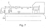
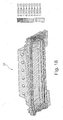
- FIG. 7 a side view of the machine tool bed shown.
- fourth cooling section 304 on the underside of the machine bed is shown a part of the flow channel system.
- FIG. 7 shown with the arrows below the machine bed, a schematic circulation of the tempering within the flow channel system or the cooling profile.
- the cooling profile connection 8 is located on the right-hand outside of the fourth cooling profile 304.
- the temperature-control medium is guided, following the schematic flow arrows, from the cooling-profile connection 8 to the left outer end of the machine bed and back.
- FIG. 8 is a refrigerated and uncooled machine tool shown in comparison.
- the illustrated machine tool comprises a stand 900 with stand recesses 10.
- a fourth cooling profile 304 At the bottom of the machine bed is a fourth cooling profile 304 and at the top of the stand 900, the upper drive 11 is shown.
- the initial position of the upper drive 110 shows a significant deviation compared to the deformation position of the upper drive 111.
- On the schematic lines 801 and 802 also the deformation of the machine bed is to be illustrated again.
- deformations of the machine tool are shown enlarged. Nevertheless, it should be noted that a significant improvement (reduction) of the bending and curvature of the machine tool can be determined by the inventive arrangement of the cooling profiles according to the invention at the various areas of the machine tool.
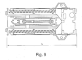
- FIG. 9 the plan view of the machine bed is shown. Particularly in machine tools with a very long machine bed, the curvatures of the machine bed have a particularly strong effect on the machining accuracy of the workpieces.
- the length of the machine tool or the length of the machine tool bed is denoted by L.
- FIGS. 10a and 10b Analogous to the arrangements of the cooling profiles on the different sides of the stand 900 in FIG. 2 , are in FIGS. 10a and 10b preferred arrangements of the cooling profiles on the stator of the machine tool shown on a concrete example.
- a fifth cooling profile 305 is disposed along an upper edge of the stand 900.
- a sixth cooling profile 306 is arranged.
- a seventh cooling profile 307 is arranged. Due to the illustrated arrangement of the cooling profiles, a compensation of the heat development at the central drive 13 from the sixth cooling profile 306 can take place to the fifth and seventh profiles of the stator.
- FIG. 10b is the rear view 12 of the stand 900 of the machine tool shown.
- the stand 900 has an eighth cooling profile 308 on its upper side and a ninth cooling profile 309 on its underside.
- the flow channel system of the machine tool according to the invention can also be regarded as a tempering device for controlling the temperature of the machine tool.
- Different channels (first and second flow channels) of the flow channel system in which the temperature control medium is circulated are arranged in first and second regions of the machine tool.
- Heat sources are arranged in the first regions and the second regions are spaced from the first regions.
- the heat input generated by the heat sources in the second regions may be lower than in the first regions.
- the first flow channels can be arranged in the first regions and the second flow channels can be arranged in the second regions.
- the flow channels can also be arranged along the edges and / or on the surfaces of the structural parts of the machine tool.
- the flow channels can be arranged on the structural parts of the machine tool such that when the tempering medium is circulated from the first flow channels into the second channels, the temperature gradient of the various regions of the machine tool can be reduced.
- FIG. 11 exemplary dimensions are shown for a particularly advantageous embodiment of the cooling profile or cross section of the cooling profile.
- a material with very high thermal conductivity is preferred for this hollow profile.
- cooling profiles in grooves which are arranged directly adjacent to the guide.
- FIG. 12 are cooling profiles in grooves, which are arranged directly next to the guide 1 and the guide 2, shown.
- arrangement of the cooling profiles 300 directly at the guides 1 and 2 optimally enables heat dissipation, so that can minimize the deformation and bending or the curvatures of the structural part of the machine tool.
- the preferred for fixing and attachment of the cooling profiles in the grooves or cutouts mounting options are in the FIGS. 13a to 13c shown.
- FIG. 13a a cooling profile 300 is shown, which is arranged in a cutout (groove 151) in the base element 15 of the structural part of the machine tool.
- the cooling profile 300 is pressed via a mounting cover 16 in the cutout so that optimum contact of the cooling profile is ensured with the base member, and so that the heat transfer is maximized.
- This is z. B. on the illustrated mounting cover 16 which is pressed onto the cooling element 300 and deformed so that the mounting cover 16 engages on the one hand in the mounting grooves on the base element and on the other hand, the surface of the cooling profile 300 adapts.
- FIG. 13b a cooling profile 300 is shown, which is pressed into a cutout in the base element 15.
- the cutout in the base member 15 is designed such that the cooling profile 300 can be pressed into the cutout of the base member so that it is fixed in the wedge-shaped part of the cutout in the base member 15.
- this slightly compressed by the neck of the cutout into the base element 15 is guided so that the cooling profile in the bulbous element of the cutout can expand again and no longer slips by itself through the neck of the cutout of the base member 15.
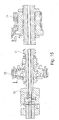
- FIG. 14 is a spindle core cooling combined with a spindle bearing cooling shown.
- a spindle bearing cooling can be provided in addition to the spindle core cooling.
- the spindle bearing cooling is realized via the second cooling bores 25 and the third cooling bores 26.
- the second cooling holes 25 are located on a cooling ring 22 which is applied to the bearing 20.
- the third cooling holes 26 are located in a cooling pot 23, which is attached to the end face of the spindle.
- the cooling ring 22 has in its interior a plurality of cooling holes, through which the temperature control medium is circulated and with the aid of which the temperature of the bearing 20 can be kept stable.
- FIG. 15 is again a cross section through the in FIG. 15 shown spindle assembly shown.
- a mother cooling is shown as an example.
- an additional second cooling ring with different cooling holes is attached to the outer circumference of the nut.
- temperature stabilization of the spindle is also achieved via the second cooling bores 25 and via the cooling bores in the second cooling ring 28.
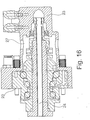
- FIG. 16 again a combined bearing and spindle cooling is shown.
- a cooling pot 23 combined with a cooling ring, which is arranged around the outer circumference of the illustrated bearing and via therein provided cooling channels of the flow channel system of a temperature of the bearing on the one hand and the spindle core 21 on the other hand causes. Due to the temperature of the spindle core 21 and at the same time also the bearing 20 of the spindle, the precision of the machine tool can be particularly increased.
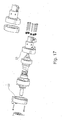
- FIG. 17 again the cooling ring 22 and the cooling pot 23 of the aforementioned temperature control on the spindle shown.
- the cooling ring 22 and the cooling pot 23 are fixed to each other via screws.
- cooling ring 22 and the cooling pot 23 are made of a cast aluminum, since a particularly high temperature stabilization of the tool spindle can be achieved.
- weight of the spindle is increased only minimally by the aluminum casting.
- FIG. 18 the displacement of the cooled cross member 29 is shown in millimeters. Due to the additional cooling on the guides of the cross member, the bending of the cross member can be significantly reduced from 12 ⁇ m to 2 ⁇ m with reference guidance. In the total displacement, the bend in the un-cooled state has a share of about 30%.
- the other 60% can be explained as follows: expansion of the x-slide by heating the ball screw nut; Extension of the cross member in the width (y-direction of the machine); Temperature differences of the cross member in the z-direction, thereby rotation about the x-axis and displacement in the y-direction.
- a required inner diameter of only 9 mm to achieve the required cooling capacity in the cross member 29 results for the tubes of the flow channel system.
- the required volume flow is 6 L / min, with the optimum flow temperature at 23 ° C. With these boundary conditions, the deformation of the machine tool can be significantly reduced.
- FIG. 19 the comparison of the maximum displacements on the cross member 29 is summarized again. The difference between the displacements with cooling and the displacements without cooling is clearly visible.
- the relocations are in FIG. 19 shown as a function of the position on the cross member. The relocation itself is in FIG. 19 shown in micrometers.
- FIG. 20 shows a simplified control loop for controlling the volume flow of the temperature control medium in the flow channel system (301-309) using the example of a machine bed 500.
- the flow channel system consists of two simplified cooling profiles 300 which each have a flow 311 and a return 312.
- the connections of the cooling profiles 300 are led to a pump 30.
- the temperature control medium is circulated in the flow channel system.
- the volume flow of the temperature control can be adjusted.
- the volume flow in the flow channel system can be regulated such that a specific differential temperature within the different regions or sections of the flow channel system is not exceeded.
- the available cross section for guiding the temperature control medium in the flow channels plays an important role.
- Another factor is the occurring heat input of the functional components in the structure of the machine tool.
- the pump can be selected so that the control of the pump power of the flow rate is always set so that the amount of the differential temperature of the temperature does not exceed a value of 3 ° C, and more preferably 1 ° C. This makes it possible to limit the deformations and in particular the curvatures and deflections of the machine tool structure in such a way that an optimum ratio between Temper istsaufwand and component machining accuracy can be achieved.
- temperatures are also measured at the top and bottom of the machine bed 500.
- the measuring points of the temperature T1 and T2 are preferably provided in the areas of the maximum temperatures occurring, in each case at the top and bottom (cold and warm side of the respective structure).
- the heat-generating functional components are in FIG. 20 exemplified by the machine table 501.
Landscapes
- Engineering & Computer Science (AREA)
- Mechanical Engineering (AREA)
- Heat Treatment Of Articles (AREA)
- Machine Tool Units (AREA)
- Machine Tool Sensing Apparatuses (AREA)
- Auxiliary Devices For Machine Tools (AREA)
- Turning (AREA)
Claims (16)
- Machine-outil comportant un bâti de machine qui est conçu par des éléments structuraux et par des composants qui sont montés sur ceux-ci et qui comprennent des composants fonctionnels générant de la chaleur pendant le fonctionnement de la machine-outil apportée par transfert thermique dans les éléments structuraux et dans les composants, comportant un système de canaux d'écoulement (301 - 309) pourvu de premiers et de seconds canaux d'écoulement et dans lequel circule un milieu de thermorégulation qui est agencé au niveau des éléments structuraux et des composants de la machine-outil dans de premières zones et dans de secondes zones espacées des premières zones, de telle sorte que suite à l'écoulement du milieu de thermorégulation, la chaleur générée par les composants fonctionnels est répartie dans le bâti de machine et dans les composants, l'apport de chaleur généré par les composants fonctionnels étant plus faible dans les secondes zones qu'il ne l'est dans les premières zones, de sorte qu'une compensation du gradient de température dans la machine-outil s'effectue exclusivement par circulation du milieu de thermorégulation dans le système de canaux d'écoulement (301 - 309),
caractérisée en ce que
les canaux d'écoulement du système de canaux d'écoulement (301 - 309) sont réalisés sous forme de profilés creux et sont agencés sur la surface des composants de la machine-outil, et
la machine-outil comprend un banc de machine (500) et un montant de machine (900), et en ce que
des canaux d'écoulement du système de canaux d'écoulement (301 - 309) sont agencés sur la face supérieure et sur la face inférieure le long des arêtes du banc de machine (500) et sur la face supérieure et sur la face inférieure le long des arêtes du montant (900). - Machine-outil selon la revendication 1,
caractérisée en ce que
le système de canaux d'écoulement (301 - 309) est agencé sur les éléments structuraux et sur les composants de la machine-outil de telle sorte que des basculements et/ou des déplacements des éléments structuraux et des composants sont empêchés. - Machine-outil selon l'une des revendications 1 à 2,
caractérisée en ce que
les canaux d'écoulement du système de canaux d'écoulement (301 - 309) sont réalisés sous forme de profilés de refroidissement (300), et en ce que le profil de refroidissement (300) comprend au moins un canal d'aller et un canal de retour pour recevoir le milieu de thermorégulation. - Machine-outil selon la revendication 3,
caractérisée en ce que
le canal d'aller est relié de façon conductrice au canal de retour, de sorte que le milieu de thermorégulation est dévié. - Machine-outil selon la revendication 3 ou 4,
caractérisée en ce que
le canal d'aller est relié au canal de retour par une plaque soudée (350) ayant une voie fraisée pour renvoyer l'aller jusque dans le retour. - Machine-outil selon l'une des revendications 3 à 5,
caractérisée en ce que
les profilés de refroidissement (300) sont vissés sur les composants de la machine-outil. - Machine-outil selon la revendication 1,
caractérisée en ce que
des canaux d'écoulement du système de canaux d'écoulement (301 - 309) sont conçus sous forme de tubes, et en ce que
la machine-outil présente des rainures (151) dans lesquelles sont montés les tubes. - Machine-outil selon la revendication 7,
caractérisée en ce que
les tubes sont fixés dans les rainures (151) par des couvercles de fixation (16). - Machine-outil selon l'une des revendications 3 à 8,
caractérisée en ce que
les tubes des canaux d'écoulement sont en cuivre. - Machine-outil selon l'une des revendications 1 à 2,
caractérisée en ce que
les canaux d'écoulement du système de canaux d'écoulement (301 - 309) sont agencés dans des perçages dans les composants et dans les éléments structuraux de la machine-outil. - Machine-outil selon l'une des revendications 1 à 8,
caractérisée en ce que
les canaux d'écoulement du système de canaux d'écoulement (301 - 309) sont agencés partiellement dans le coeur de broche (21) et dans le support de broche (20). - Machine-outil selon l'une des revendications 1 à 11,
caractérisée en ce que
une pompe (30) pour réguler le courant volumique du milieu de thermorégulation est conçue de telle sorte que le montant de la différence de température du milieu de thermorégulation dans les différentes zones du système de canaux d'écoulement (301 - 309) est limité au maximum à 3 °C. - Machine-outil selon l'une des revendications 1 à 12,
caractérisée en ce que
pour détecter un gradient de température, il est prévu un premier capteur de température dans une zone des composants fonctionnels et au moins un second capteur de température dans une zone dépourvue de composants fonctionnels, sur la machine-outil. - Machine-outil selon la revendication 13,
caractérisée en ce que
il est prévu une unité de régulation et de commande qui est conçue de telle sorte que le courant volumique du milieu de thermorégulation est régulé par la puissance de la pompe (30), de telle sorte que le montant de la température différentielle entre le premier et le second capteur de température est limité au maximum à 3 °C. - Procédé de thermorégulation d'une machine-outil comportant un bâti de machine qui est conçu par des éléments structuraux et par des composants qui sont montés sur ceux-ci et qui comprennent des composants fonctionnels générant de la chaleur pendant le fonctionnement de la machine-outil apportée par transfert thermique dans les éléments structuraux et dans les composants,
comportant de premiers et de seconds canaux d'écoulement formant un système de canaux d'écoulement (301 - 309) agencé au niveau des éléments structuraux et des composants de la machine-outil dans de premières zones et dans de secondes zones espacées des premières zones,
l'apport de chaleur généré par les composants fonctionnels étant plus faible dans les secondes zones qu'il ne l'est dans les premières zones, et
les canaux d'écoulement du système de canaux d'écoulement (301 - 309) étant réalisés sous forme de profilés creux et agencés sur la surface des composants de la machine-outil, et
la machine-outil comprenant un banc de machine (500) et un montant de machine (900), et
des canaux d'écoulement du système de canaux d'écoulement (301 - 309) étant agencés sur la face supérieure et sur la face inférieure le long des arêtes du banc de machine (500) et sur la face supérieure et sur la face inférieure le long des arêtes du montant (900),
comprenant l'étape consistant à
compenser le gradient de température dans la machine-outil exclusivement par circulation du milieu de thermorégulation dans le système de canaux d'écoulement (301 - 309). - Procédé de thermorégulation d'une machine-outil selon la revendication 15,
caractérisé par l'étape consistant à
réguler le courant volumique du milieu de thermorégulation dans les canaux d'écoulement par une pompe (30) de telle sorte que le montant de la température différentielle du milieu de thermorégulation dans les différentes zones du système de canaux d'écoulement (301 - 309) est au maximum de 3 °C, de préférence de 1 °C.
Applications Claiming Priority (1)
| Application Number | Priority Date | Filing Date | Title |
|---|---|---|---|
| DE102014202879.5A DE102014202879A1 (de) | 2014-02-17 | 2014-02-17 | Werkzeugmaschine mit einem aus Strukturteilen aufgebauten Maschinengestell |
Publications (2)
| Publication Number | Publication Date |
|---|---|
| EP2907620A1 EP2907620A1 (fr) | 2015-08-19 |
| EP2907620B1 true EP2907620B1 (fr) | 2019-06-05 |
Family
ID=52596743
Family Applications (1)
| Application Number | Title | Priority Date | Filing Date |
|---|---|---|---|
| EP15155266.8A Active EP2907620B1 (fr) | 2014-02-17 | 2015-02-16 | Machine-outil dotée d'un bâti de machine composé d'éléments structuraux et méthode pour celle-ci |
Country Status (7)
| Country | Link |
|---|---|
| US (1) | US10118267B2 (fr) |
| EP (1) | EP2907620B1 (fr) |
| JP (1) | JP6670545B2 (fr) |
| KR (1) | KR20150097425A (fr) |
| CN (1) | CN104858709B (fr) |
| DE (1) | DE102014202879A1 (fr) |
| ES (1) | ES2738326T3 (fr) |
Families Citing this family (6)
| Publication number | Priority date | Publication date | Assignee | Title |
|---|---|---|---|---|
| CN108381869A (zh) * | 2017-09-26 | 2018-08-10 | 蒋米娜 | 双色叠层热流道系统 |
| JP6603288B2 (ja) * | 2017-10-25 | 2019-11-06 | ファナック株式会社 | 工作機械の切削液供給装置 |
| CN110757175B (zh) * | 2018-11-22 | 2020-09-04 | 玉环精格机床附件有限公司 | 一种用于数控机床领域的固定装置 |
| GB201915900D0 (en) * | 2019-11-01 | 2019-12-18 | Fives Landis Ltd | Temperature controls in machine tools |
| CN113427317A (zh) * | 2021-05-27 | 2021-09-24 | 北京精雕科技集团有限公司 | 一种机床结构件的温控结构及制造方法 |
| CN115091219A (zh) * | 2022-08-08 | 2022-09-23 | 南京苏元数控机床有限公司 | 一种精密机床线轨 |
Family Cites Families (19)
| Publication number | Priority date | Publication date | Assignee | Title |
|---|---|---|---|---|
| US2221127A (en) * | 1938-07-27 | 1940-11-12 | Westinghouse Electric & Mfg Co | Temperature control means for gear cutting |
| DE2143143A1 (de) * | 1971-06-29 | 1973-01-11 | Rostock Dieselmotoren | Einrichtung zur vermeidung von thermischen verformungen an maschinenteilen, insbesondere fuehrungsbahnen von werkzeugmaschinen |
| JPS61214929A (ja) * | 1985-03-22 | 1986-09-24 | Mitsubishi Heavy Ind Ltd | 工作機械用ベツド |
| DE3828305A1 (de) * | 1988-08-20 | 1990-02-22 | Salje Ernst | Verfahren zur thermischen beeinflussung von werkzeugmachinen, vorrichtung zur durchfuehrung des verfahrens und bauteil |
| JPH0753027Y2 (ja) | 1990-10-02 | 1995-12-06 | 日本トムソン株式会社 | 遠隔操作形自在旋回ノズル |
| DE4419441C2 (de) * | 1994-06-03 | 1996-07-11 | Ltg Lufttechnische Gmbh | Verfahren zum Kühlen/Konditionieren von Luft |
| DE19846260A1 (de) * | 1998-10-07 | 2000-04-13 | Schneider Gmbh & Co Kg | Vorrichtung zum Bearbeiten optischer Linsen durch Schleifen und Polieren |
| JP2000117571A (ja) * | 1998-10-14 | 2000-04-25 | Kitamura Mach Co Ltd | 工作機械 |
| US6089797A (en) * | 1998-11-30 | 2000-07-18 | Excellon Automation, Co. | Thermal equalization system |
| JP2002239857A (ja) * | 2001-02-13 | 2002-08-28 | Makino Milling Mach Co Ltd | 熱変形抑制機能を備えた工作機械 |
| ITMI20022077A1 (it) * | 2002-10-02 | 2004-04-03 | Parpas S P A | Impianto di condizionamento per una macchina operatrice, in particolare per una macchina utensile |
| JP2005262379A (ja) * | 2004-03-18 | 2005-09-29 | Niigata Machine Techno Co Ltd | 工作機械 |
| JP4596480B2 (ja) * | 2006-07-21 | 2010-12-08 | 株式会社ソディック | 工作機械および同工作機械における熱伝導緩衝体の厚み設定方法 |
| DE202009009424U1 (de) * | 2009-07-09 | 2010-11-18 | P + L Gmbh & Co. Kg | Werkzeugmaschine mit luftgekühlter Spindelwelle |
| JP5084848B2 (ja) * | 2010-01-13 | 2012-11-28 | 株式会社牧野フライス製作所 | 加工機械設備 |
| IT1402471B1 (it) | 2010-09-08 | 2013-09-13 | Camozzi Machine Tools S P A Ora Innse Berardi S P A | Macchina utensile di grandi dimensioni munita di un dispositivo per la rilevazione e la correzione delle deformazioni |
| DE202010016616U1 (de) * | 2010-12-15 | 2011-02-17 | Deckel Maho Seebach Gmbh | Führungssystem für Werkzeugmaschinen |
| DE102011104892A1 (de) * | 2011-06-07 | 2012-12-13 | Franz Kessler Gmbh | Werkzeugmaschine mit einer elektrischen Motoreinheit |
| DE102011111287B4 (de) * | 2011-08-26 | 2018-05-09 | Kern Micro- Und Feinwerktechnik Gmbh & Co. Kg | Werkzeugmaschine |
-
2014
- 2014-02-17 DE DE102014202879.5A patent/DE102014202879A1/de not_active Ceased
-
2015
- 2015-02-16 KR KR1020150023672A patent/KR20150097425A/ko not_active Withdrawn
- 2015-02-16 JP JP2015027936A patent/JP6670545B2/ja active Active
- 2015-02-16 EP EP15155266.8A patent/EP2907620B1/fr active Active
- 2015-02-16 ES ES15155266T patent/ES2738326T3/es active Active
- 2015-02-17 US US14/624,034 patent/US10118267B2/en active Active
- 2015-02-17 CN CN201510086263.3A patent/CN104858709B/zh active Active
Non-Patent Citations (1)
| Title |
|---|
| None * |
Also Published As
| Publication number | Publication date |
|---|---|
| US10118267B2 (en) | 2018-11-06 |
| JP2015163427A (ja) | 2015-09-10 |
| CN104858709A (zh) | 2015-08-26 |
| EP2907620A1 (fr) | 2015-08-19 |
| DE102014202879A1 (de) | 2015-08-20 |
| US20150231750A1 (en) | 2015-08-20 |
| JP6670545B2 (ja) | 2020-03-25 |
| ES2738326T3 (es) | 2020-01-22 |
| KR20150097425A (ko) | 2015-08-26 |
| CN104858709B (zh) | 2020-09-29 |
Similar Documents
| Publication | Publication Date | Title |
|---|---|---|
| EP2907620B1 (fr) | Machine-outil dotée d'un bâti de machine composé d'éléments structuraux et méthode pour celle-ci | |
| EP2907619B1 (fr) | Machine-outil dotée de composants de fonction produisant de la chaleur lors du fonctionnement et méthode pour celle-ci | |
| EP2651599B1 (fr) | Système de guidage pour machines-outils maintenu au moyen de barres de refroidissement | |
| EP1907171B1 (fr) | Rail de guidage lineaire pour un systeme de guidage lineaire pourvu d'une rainure a fluide de refroidissement | |
| DE2258258C2 (de) | Kühlsystem für elektronische Bauelemente | |
| EP3155275B1 (fr) | Guidage linéaire composite pourvu de moyens de fixation | |
| EP2106891A1 (fr) | Plaque chauffante pour outils | |
| DE102013225104A1 (de) | Verfahren zum Abtrennen von Scheiben von einem Werkstück mittels einer Drahtsäge | |
| EP2408579B1 (fr) | Porte-outil à mandrin de frettage | |
| DE102007029571A1 (de) | Verfahren zum Einstellen der Vorspannung eines Wälzlagers, Wälzlagereinheit mit einstellbarer Vorspannung sowie Rundtisch und Spindel mit entsprechender Wälzlagereinheit | |
| EP1992829A1 (fr) | Procédé de réglage de la précontrainte d'un palier à roulement, unité de palier à roulement dotée d'une précontrainte réglable ainsi que table ronde et broche dotée d'une unité de palier à roulement correspondante | |
| WO2005025801A1 (fr) | Machine-outil comprenant un dispositif de reglage qui presente une nervure et un dispositif thermique et qui est situe entre deux pieces de machine | |
| DE4113667C2 (fr) | ||
| EP2190277A1 (fr) | Dispositif destiné à la fixation d'un composant électronique | |
| DE102010033816A1 (de) | Temperiertes Werkzeug | |
| DE2552969A1 (de) | Fuehrungsrolle fuer stranggussanlagen, mit auf einer mehrfach gelagerten achse angeordneten rollenabschnitten | |
| EP1378319B1 (fr) | Système d'avance à moteurs linéaires et poupée de machine-outil avec un tel système d'avance | |
| DE20022029U1 (de) | Einrichtung zum Beseitigen thermischer Verformungen | |
| DE102013101790A1 (de) | Temperiervorrichtung, Anlage zur Temperierung und Verfahren zur Temperierung | |
| DE102016208918B4 (de) | Führungsschiene mit Temperiernut und Verschlussteil | |
| EP0582213B1 (fr) | Assemblage à pression avec des cellules semi-conductrices et des boîtes de refroidissement | |
| DE102022114550B3 (de) | Kühlanordnung zum Kühlen einer Maschine und Verfahren hierzu | |
| EP4186094B1 (fr) | Agencement de refroidissement et module de moteur | |
| DE102007007247B4 (de) | Anordnung und Verfahren zur Verhinderung der Wärmeleitung zwischen einer Wärmequelle und einer temperatursensiblen Baugruppe | |
| EP2116327A1 (fr) | Machine-outil dotée d'un tuyau de chauffage |
Legal Events
| Date | Code | Title | Description |
|---|---|---|---|
| PUAI | Public reference made under article 153(3) epc to a published international application that has entered the european phase |
Free format text: ORIGINAL CODE: 0009012 |
|
| AK | Designated contracting states |
Kind code of ref document: A1 Designated state(s): AL AT BE BG CH CY CZ DE DK EE ES FI FR GB GR HR HU IE IS IT LI LT LU LV MC MK MT NL NO PL PT RO RS SE SI SK SM TR |
|
| AX | Request for extension of the european patent |
Extension state: BA ME |
|
| 17P | Request for examination filed |
Effective date: 20160219 |
|
| RBV | Designated contracting states (corrected) |
Designated state(s): AL AT BE BG CH CY CZ DE DK EE ES FI FR GB GR HR HU IE IS IT LI LT LU LV MC MK MT NL NO PL PT RO RS SE SI SK SM TR |
|
| STAA | Information on the status of an ep patent application or granted ep patent |
Free format text: STATUS: EXAMINATION IS IN PROGRESS |
|
| 17Q | First examination report despatched |
Effective date: 20161209 |
|
| GRAP | Despatch of communication of intention to grant a patent |
Free format text: ORIGINAL CODE: EPIDOSNIGR1 |
|
| STAA | Information on the status of an ep patent application or granted ep patent |
Free format text: STATUS: GRANT OF PATENT IS INTENDED |
|
| INTG | Intention to grant announced |
Effective date: 20181212 |
|
| GRAS | Grant fee paid |
Free format text: ORIGINAL CODE: EPIDOSNIGR3 |
|
| GRAA | (expected) grant |
Free format text: ORIGINAL CODE: 0009210 |
|
| STAA | Information on the status of an ep patent application or granted ep patent |
Free format text: STATUS: THE PATENT HAS BEEN GRANTED |
|
| AK | Designated contracting states |
Kind code of ref document: B1 Designated state(s): AL AT BE BG CH CY CZ DE DK EE ES FI FR GB GR HR HU IE IS IT LI LT LU LV MC MK MT NL NO PL PT RO RS SE SI SK SM TR |
|
| REG | Reference to a national code |
Ref country code: GB Ref legal event code: FG4D Free format text: NOT ENGLISH |
|
| REG | Reference to a national code |
Ref country code: CH Ref legal event code: EP |
|
| REG | Reference to a national code |
Ref country code: AT Ref legal event code: REF Ref document number: 1139515 Country of ref document: AT Kind code of ref document: T Effective date: 20190615 |
|
| REG | Reference to a national code |
Ref country code: IE Ref legal event code: FG4D Free format text: LANGUAGE OF EP DOCUMENT: GERMAN |
|
| REG | Reference to a national code |
Ref country code: DE Ref legal event code: R096 Ref document number: 502015009202 Country of ref document: DE |
|
| REG | Reference to a national code |
Ref country code: NL Ref legal event code: MP Effective date: 20190605 |
|
| REG | Reference to a national code |
Ref country code: LT Ref legal event code: MG4D |
|
| PG25 | Lapsed in a contracting state [announced via postgrant information from national office to epo] |
Ref country code: AL Free format text: LAPSE BECAUSE OF FAILURE TO SUBMIT A TRANSLATION OF THE DESCRIPTION OR TO PAY THE FEE WITHIN THE PRESCRIBED TIME-LIMIT Effective date: 20190605 Ref country code: NO Free format text: LAPSE BECAUSE OF FAILURE TO SUBMIT A TRANSLATION OF THE DESCRIPTION OR TO PAY THE FEE WITHIN THE PRESCRIBED TIME-LIMIT Effective date: 20190905 Ref country code: SE Free format text: LAPSE BECAUSE OF FAILURE TO SUBMIT A TRANSLATION OF THE DESCRIPTION OR TO PAY THE FEE WITHIN THE PRESCRIBED TIME-LIMIT Effective date: 20190605 Ref country code: FI Free format text: LAPSE BECAUSE OF FAILURE TO SUBMIT A TRANSLATION OF THE DESCRIPTION OR TO PAY THE FEE WITHIN THE PRESCRIBED TIME-LIMIT Effective date: 20190605 Ref country code: LT Free format text: LAPSE BECAUSE OF FAILURE TO SUBMIT A TRANSLATION OF THE DESCRIPTION OR TO PAY THE FEE WITHIN THE PRESCRIBED TIME-LIMIT Effective date: 20190605 Ref country code: HR Free format text: LAPSE BECAUSE OF FAILURE TO SUBMIT A TRANSLATION OF THE DESCRIPTION OR TO PAY THE FEE WITHIN THE PRESCRIBED TIME-LIMIT Effective date: 20190605 |
|
| PG25 | Lapsed in a contracting state [announced via postgrant information from national office to epo] |
Ref country code: RS Free format text: LAPSE BECAUSE OF FAILURE TO SUBMIT A TRANSLATION OF THE DESCRIPTION OR TO PAY THE FEE WITHIN THE PRESCRIBED TIME-LIMIT Effective date: 20190605 Ref country code: LV Free format text: LAPSE BECAUSE OF FAILURE TO SUBMIT A TRANSLATION OF THE DESCRIPTION OR TO PAY THE FEE WITHIN THE PRESCRIBED TIME-LIMIT Effective date: 20190605 Ref country code: BG Free format text: LAPSE BECAUSE OF FAILURE TO SUBMIT A TRANSLATION OF THE DESCRIPTION OR TO PAY THE FEE WITHIN THE PRESCRIBED TIME-LIMIT Effective date: 20190905 Ref country code: GR Free format text: LAPSE BECAUSE OF FAILURE TO SUBMIT A TRANSLATION OF THE DESCRIPTION OR TO PAY THE FEE WITHIN THE PRESCRIBED TIME-LIMIT Effective date: 20190906 |
|
| REG | Reference to a national code |
Ref country code: ES Ref legal event code: FG2A Ref document number: 2738326 Country of ref document: ES Kind code of ref document: T3 Effective date: 20200122 |
|
| PG25 | Lapsed in a contracting state [announced via postgrant information from national office to epo] |
Ref country code: PT Free format text: LAPSE BECAUSE OF FAILURE TO SUBMIT A TRANSLATION OF THE DESCRIPTION OR TO PAY THE FEE WITHIN THE PRESCRIBED TIME-LIMIT Effective date: 20191007 Ref country code: EE Free format text: LAPSE BECAUSE OF FAILURE TO SUBMIT A TRANSLATION OF THE DESCRIPTION OR TO PAY THE FEE WITHIN THE PRESCRIBED TIME-LIMIT Effective date: 20190605 Ref country code: RO Free format text: LAPSE BECAUSE OF FAILURE TO SUBMIT A TRANSLATION OF THE DESCRIPTION OR TO PAY THE FEE WITHIN THE PRESCRIBED TIME-LIMIT Effective date: 20190605 Ref country code: SK Free format text: LAPSE BECAUSE OF FAILURE TO SUBMIT A TRANSLATION OF THE DESCRIPTION OR TO PAY THE FEE WITHIN THE PRESCRIBED TIME-LIMIT Effective date: 20190605 Ref country code: CZ Free format text: LAPSE BECAUSE OF FAILURE TO SUBMIT A TRANSLATION OF THE DESCRIPTION OR TO PAY THE FEE WITHIN THE PRESCRIBED TIME-LIMIT Effective date: 20190605 Ref country code: NL Free format text: LAPSE BECAUSE OF FAILURE TO SUBMIT A TRANSLATION OF THE DESCRIPTION OR TO PAY THE FEE WITHIN THE PRESCRIBED TIME-LIMIT Effective date: 20190605 |
|
| PG25 | Lapsed in a contracting state [announced via postgrant information from national office to epo] |
Ref country code: SM Free format text: LAPSE BECAUSE OF FAILURE TO SUBMIT A TRANSLATION OF THE DESCRIPTION OR TO PAY THE FEE WITHIN THE PRESCRIBED TIME-LIMIT Effective date: 20190605 Ref country code: IS Free format text: LAPSE BECAUSE OF FAILURE TO SUBMIT A TRANSLATION OF THE DESCRIPTION OR TO PAY THE FEE WITHIN THE PRESCRIBED TIME-LIMIT Effective date: 20191005 |
|
| REG | Reference to a national code |
Ref country code: DE Ref legal event code: R097 Ref document number: 502015009202 Country of ref document: DE |
|
| PG25 | Lapsed in a contracting state [announced via postgrant information from national office to epo] |
Ref country code: TR Free format text: LAPSE BECAUSE OF FAILURE TO SUBMIT A TRANSLATION OF THE DESCRIPTION OR TO PAY THE FEE WITHIN THE PRESCRIBED TIME-LIMIT Effective date: 20190605 |
|
| PLBE | No opposition filed within time limit |
Free format text: ORIGINAL CODE: 0009261 |
|
| STAA | Information on the status of an ep patent application or granted ep patent |
Free format text: STATUS: NO OPPOSITION FILED WITHIN TIME LIMIT |
|
| PG25 | Lapsed in a contracting state [announced via postgrant information from national office to epo] |
Ref country code: PL Free format text: LAPSE BECAUSE OF FAILURE TO SUBMIT A TRANSLATION OF THE DESCRIPTION OR TO PAY THE FEE WITHIN THE PRESCRIBED TIME-LIMIT Effective date: 20190605 Ref country code: DK Free format text: LAPSE BECAUSE OF FAILURE TO SUBMIT A TRANSLATION OF THE DESCRIPTION OR TO PAY THE FEE WITHIN THE PRESCRIBED TIME-LIMIT Effective date: 20190605 |
|
| 26N | No opposition filed |
Effective date: 20200306 |
|
| PG25 | Lapsed in a contracting state [announced via postgrant information from national office to epo] |
Ref country code: SI Free format text: LAPSE BECAUSE OF FAILURE TO SUBMIT A TRANSLATION OF THE DESCRIPTION OR TO PAY THE FEE WITHIN THE PRESCRIBED TIME-LIMIT Effective date: 20190605 |
|
| REG | Reference to a national code |
Ref country code: BE Ref legal event code: MM Effective date: 20200229 |
|
| PG25 | Lapsed in a contracting state [announced via postgrant information from national office to epo] |
Ref country code: LU Free format text: LAPSE BECAUSE OF NON-PAYMENT OF DUE FEES Effective date: 20200216 Ref country code: MC Free format text: LAPSE BECAUSE OF FAILURE TO SUBMIT A TRANSLATION OF THE DESCRIPTION OR TO PAY THE FEE WITHIN THE PRESCRIBED TIME-LIMIT Effective date: 20190605 |
|
| PG25 | Lapsed in a contracting state [announced via postgrant information from national office to epo] |
Ref country code: IE Free format text: LAPSE BECAUSE OF NON-PAYMENT OF DUE FEES Effective date: 20200216 |
|
| PG25 | Lapsed in a contracting state [announced via postgrant information from national office to epo] |
Ref country code: BE Free format text: LAPSE BECAUSE OF NON-PAYMENT OF DUE FEES Effective date: 20200229 |
|
| REG | Reference to a national code |
Ref country code: AT Ref legal event code: MM01 Ref document number: 1139515 Country of ref document: AT Kind code of ref document: T Effective date: 20200216 |
|
| PG25 | Lapsed in a contracting state [announced via postgrant information from national office to epo] |
Ref country code: AT Free format text: LAPSE BECAUSE OF NON-PAYMENT OF DUE FEES Effective date: 20200216 |
|
| PG25 | Lapsed in a contracting state [announced via postgrant information from national office to epo] |
Ref country code: MT Free format text: LAPSE BECAUSE OF FAILURE TO SUBMIT A TRANSLATION OF THE DESCRIPTION OR TO PAY THE FEE WITHIN THE PRESCRIBED TIME-LIMIT Effective date: 20190605 Ref country code: CY Free format text: LAPSE BECAUSE OF FAILURE TO SUBMIT A TRANSLATION OF THE DESCRIPTION OR TO PAY THE FEE WITHIN THE PRESCRIBED TIME-LIMIT Effective date: 20190605 |
|
| PG25 | Lapsed in a contracting state [announced via postgrant information from national office to epo] |
Ref country code: MK Free format text: LAPSE BECAUSE OF FAILURE TO SUBMIT A TRANSLATION OF THE DESCRIPTION OR TO PAY THE FEE WITHIN THE PRESCRIBED TIME-LIMIT Effective date: 20190605 |
|
| PGFP | Annual fee paid to national office [announced via postgrant information from national office to epo] |
Ref country code: CH Payment date: 20250301 Year of fee payment: 11 |
|
| REG | Reference to a national code |
Ref country code: CH Ref legal event code: U11 Free format text: ST27 STATUS EVENT CODE: U-0-0-U10-U11 (AS PROVIDED BY THE NATIONAL OFFICE) Effective date: 20260301 |
|
| PGFP | Annual fee paid to national office [announced via postgrant information from national office to epo] |
Ref country code: GB Payment date: 20260219 Year of fee payment: 12 |
|
| PGFP | Annual fee paid to national office [announced via postgrant information from national office to epo] |
Ref country code: ES Payment date: 20260319 Year of fee payment: 12 |
|
| PGFP | Annual fee paid to national office [announced via postgrant information from national office to epo] |
Ref country code: DE Payment date: 20260228 Year of fee payment: 12 |
|
| PGFP | Annual fee paid to national office [announced via postgrant information from national office to epo] |
Ref country code: IT Payment date: 20260227 Year of fee payment: 12 |
|
| PGFP | Annual fee paid to national office [announced via postgrant information from national office to epo] |
Ref country code: FR Payment date: 20260219 Year of fee payment: 12 |