EP2913557B1 - Variateur de vitesse de rouleau planétaire - Google Patents
Variateur de vitesse de rouleau planétaire Download PDFInfo
- Publication number
- EP2913557B1 EP2913557B1 EP14196200.1A EP14196200A EP2913557B1 EP 2913557 B1 EP2913557 B1 EP 2913557B1 EP 14196200 A EP14196200 A EP 14196200A EP 2913557 B1 EP2913557 B1 EP 2913557B1
- Authority
- EP
- European Patent Office
- Prior art keywords
- shaft
- planet
- carrier
- planet roller
- center
- Prior art date
- Legal status (The legal status is an assumption and is not a legal conclusion. Google has not performed a legal analysis and makes no representation as to the accuracy of the status listed.)
- Active
Links
Images




Classifications
-
- F—MECHANICAL ENGINEERING; LIGHTING; HEATING; WEAPONS; BLASTING
- F16—ENGINEERING ELEMENTS AND UNITS; GENERAL MEASURES FOR PRODUCING AND MAINTAINING EFFECTIVE FUNCTIONING OF MACHINES OR INSTALLATIONS; THERMAL INSULATION IN GENERAL
- F16H—GEARING
- F16H13/00—Gearing for conveying rotary motion with constant gear ratio by friction between rotary members
- F16H13/06—Gearing for conveying rotary motion with constant gear ratio by friction between rotary members with members having orbital motion
- F16H13/08—Gearing for conveying rotary motion with constant gear ratio by friction between rotary members with members having orbital motion with balls or with rollers acting in a similar manner
-
- F—MECHANICAL ENGINEERING; LIGHTING; HEATING; WEAPONS; BLASTING
- F16—ENGINEERING ELEMENTS AND UNITS; GENERAL MEASURES FOR PRODUCING AND MAINTAINING EFFECTIVE FUNCTIONING OF MACHINES OR INSTALLATIONS; THERMAL INSULATION IN GENERAL
- F16H—GEARING
- F16H13/00—Gearing for conveying rotary motion with constant gear ratio by friction between rotary members
- F16H13/06—Gearing for conveying rotary motion with constant gear ratio by friction between rotary members with members having orbital motion
-
- F—MECHANICAL ENGINEERING; LIGHTING; HEATING; WEAPONS; BLASTING
- F16—ENGINEERING ELEMENTS AND UNITS; GENERAL MEASURES FOR PRODUCING AND MAINTAINING EFFECTIVE FUNCTIONING OF MACHINES OR INSTALLATIONS; THERMAL INSULATION IN GENERAL
- F16H—GEARING
- F16H13/00—Gearing for conveying rotary motion with constant gear ratio by friction between rotary members
- F16H13/10—Means for influencing the pressure between the members
- F16H13/14—Means for influencing the pressure between the members for automatically varying the pressure mechanically
-
- F—MECHANICAL ENGINEERING; LIGHTING; HEATING; WEAPONS; BLASTING
- F16—ENGINEERING ELEMENTS AND UNITS; GENERAL MEASURES FOR PRODUCING AND MAINTAINING EFFECTIVE FUNCTIONING OF MACHINES OR INSTALLATIONS; THERMAL INSULATION IN GENERAL
- F16H—GEARING
- F16H57/00—General details of gearing
- F16H57/08—General details of gearing of gearings with members having orbital motion
- F16H57/082—Planet carriers
-
- F—MECHANICAL ENGINEERING; LIGHTING; HEATING; WEAPONS; BLASTING
- F16—ENGINEERING ELEMENTS AND UNITS; GENERAL MEASURES FOR PRODUCING AND MAINTAINING EFFECTIVE FUNCTIONING OF MACHINES OR INSTALLATIONS; THERMAL INSULATION IN GENERAL
- F16H—GEARING
- F16H57/00—General details of gearing
- F16H57/08—General details of gearing of gearings with members having orbital motion
- F16H2057/085—Bearings for orbital gears
Definitions
- the invention relates to a planet roller speed changer.
- JP 2003-161351 A there is a conventional planet roller speed changer (traction drive) in which each of cylindrical planet rollers is rotatably supported in a loosely fitted state by a pin that passes through the inner periphery of the planet roller and that protrudes from a carrier.
- a cylindrical bushing is fixedly fitted onto the outer periphery of each pin. Because each planet roller is in the loosely fitted state, there is a clearance between the inner periphery of the planet roller and the outer periphery of a corresponding one of the bushings.
- the planet roller speed changer is mounted transversely in an apparatus such as an image forming apparatus (i.e., mounted in a state where an input shaft and an output shaft of the planet roller speed changer extend along the horizontal direction) in some cases.
- the carrier In such a mounted state, the carrier may be displaced downward from a prescribed position under its own weight.
- the revolution of the pin may be promoted. Due to a change in the relative position between the planet roller and the pin caused by the misalignment of the center of rotation of the carrier with the center of revolutions of the planet rollers, rotation of the carrier is advanced or delayed when the output shaft is rotating. When the outer peripheral face of the bushing contacts the input shaft side-portion of the inner periphery of the planet roller, the rotation of the carrier is advanced or delayed significantly. As a result, large rotational fluctuations may occur in the planet roller speed changer.
- a planet roller speed changer having the features of the preamble of claim 1 is known from GB 585 876 A .
- One object of the invention is to provide a planet roller speed changer with a high degree of rotation accuracy, in which rotational fluctuations due to misalignment of the center of rotation of a carrier with the center of revolutions of planet rollers are restricted even if the misalignment occurs.
- FIG. 1 is a view illustrating the schematic configuration of a power transmitting device 1 of an image forming apparatus such as a printer, in which a planet roller speed changer 5 according to a first embodiment of the invention is mounted.
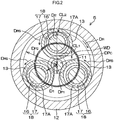
- FIG. 2 is a cross-sectional view taken along the line II-II in FIG. 1 .
- the power transmitting device 1 of the image forming apparatus includes a body 2 to be driven (hereinafter, referred to as "driven body 2"), a planet roller speed changing unit 3, and a coupling 7.
- the driven body 2 is driven to be rotated by the planet roller speed changing unit 3.
- the coupling 7 couples a driven body input shaft 4 of the driven body 2 and an output shaft 6 of the planet roller speed changer 5 to each other.
- the planet roller speed changing unit 3 is mounted transversely so that the output shaft 6 extends horizontally.
- the planet roller speed changing unit 3 includes an electric motor 8, the planet roller speed changer 5, and a housing 9.
- the housing 9 houses the electric motor 8 and the planet roller speed changer 5 together with each other.
- the housing 9 includes a first housing 9A made of, for example, aluminum, and a second housing 9B made of, for example, aluminum.
- the first housing 9A houses and holds the electric motor 8.
- the second housing 9B houses and holds a part of the output shaft 6 and a carrier 10, which will be described later.
- the planet roller speed changer 5 includes an input shaft 11, a stationary ring (sun ring) 12, a plurality of (for example, three in the present embodiment) planet rollers 13, the output shaft 6, and the carrier 10.
- a motor shaft 8A of the electric motor 8 is coupled to the input shaft 11. Note that the motor shaft 8A may be provided as the input shaft 11.
- the stationary ring 12 is fixedly disposed between the first housing 9A and the second housing 9B so as to be concentric with the input shaft 11.
- the stationary ring 12 has an annular shape, and is made of, for example, bearing steel.
- the first housing 9A, the stationary ring 12 and the second housing 9B are fixed together with a plurality of bolts 15.
- the planet rollers 13 are housed and disposed in the stationary ring 12.
- the planet rollers 13 are arranged at equal angular intervals in an annular space formed between the stationary ring 12 and the input shaft 11.
- Each of the planet rollers 13 is disposed so as to be in rolling contact with both the outer peripheral face of the input shaft 11 and the inner peripheral face of the stationary ring 12 via traction oil in a pressure contact state.
- Each of the planet rollers 13 has a cylindrical shape (or an annular shape), and is made of, for example, bearing steel.
- the carrier 10 has a disc shape.
- columnar pins 16, of which number is the same as the number of planet rollers 13, are projected perpendicularly to the one side face 10A.
- the planet rollers 13 are disposed so as to be perpendicular to the single carrier 10.
- the pins 16 may be components formed separately from the carrier 10 as illustrated in FIG. 1 , or may be formed integrally with the carrier 10.
- Each pin 16 passes through a corresponding one of the planet rollers 13, and the planet roller 13 is supported rotatably in a loosely fitted state by the pin 16.
- Each of the pins 16 has a columnar shape, and is made of, for example, bearing steel.
- a cylindrical bushing 17 is interposed between the planet roller 13 and the pin 16 in each set.
- the bushing 17 has the outer peripheral face 17A (hereinafter, sometimes referred to as "outer periphery of a shaft portion 18") formed of a cylindrical face.
- the thickness of the bushing 17 is uniform over the entire region in its circumferential direction.
- the bushing 17 is made of, for example, resin or ceramics, and is fixed onto the outer periphery of the pin 16 by interference fit.
- the pin 16 and the bushing 17 constitute the shaft portion 18.
- the output shaft 6 is fixed to the other side face (left side face in FIG. 1 ) 10C of the carrier 10. An intermediate portion of the output shaft 6 is supported at one point by the second housing 9B via a single rolling bearing 19. Thus, the output shaft 6 is rotatably disposed.
- Rotary driving force from the electric motor 8 is applied to the input shaft 11, whereby each planet roller 13 rotates about its axis in a prescribed rotational direction D RS , and in addition, the planet rollers 13 revolve in a prescribed revolving direction D R .
- the carrier 10 rotates (about its axis) due to the revolutions of the planet rollers 13.
- Rotary driving force of the carrier 10 is taken out from the planet roller speed changer 5 via the output shaft 6. With the rotary driving force, the driven body 2 of the image forming apparatus is driven to be rotated.
- a clearance is formed between the inner periphery of each planet roller 13 and the outer periphery of a corresponding one of the bushings 17.
- the position and outer diameter of each pin 16 and the inner and outer diameters of each bushing 17 are set such that, in the case where the center of each pin 16 (the center of each shaft portion 18), the center of the corresponding planet roller 13, and the center of the input shaft 11 are aligned on a single straight line, a clearance CL 1 between the shaft portion 18 and the planet roller 13 on the input shaft 11 side is larger than a clearance CL 2 between the shaft portion 18 and the planet roller 13 on the stationary ring 12 side.
- D 1 is the distance from the center of rotation of the carrier 10 to the innermost position of the outer periphery of each shaft portion 18 in the radial direction of the planet roller speed changer 5
- D P1 is the radius (inscribed radius) of a circle around the center of rotation of the carrier 10, at the innermost position in the radial direction of the planet roller speed changer 5, among positions at which each of the planet rollers 13 contacts the corresponding shaft portion 18.
- D 2 is the distance from the center of rotation of the carrier 10 to the outermost position of the outer periphery of the shaft portion 18 in the radial direction of the planet roller speed changer 5
- D P2 is the radius (circumscribed radius) of a circle around the center of rotation of the carrier 10, at the outermost position in the radial direction of the planet roller speed changer 5, among positions at which each of the planet rollers 13 contacts the corresponding shaft portion 18.
- the position of the outer periphery of each of the shaft portions 18 is set such that a pitch circle diameter DP C of the carrier 10 is larger than a value WD obtained by doubling the inter-axis distance between the input shaft 11 and each planet roller 13.
- the pitch circle diameter DP C is expressed by Expression (3) indicated below, and the value WD obtained by doubling the inter-axis distance between the input shaft 11 and each planet roller 13 is expressed by Expression (4) indicated below.
- D p is the outer diameter of each planet roller 13
- D S is the outer diameter of the input shaft 11.
- the carrier 10 may be displaced downward from a prescribed position under its own weight (the carrier 10 may be displaced in a direction that intersects with the axial direction of the output shaft 6).
- the carrier 10 is easily displaced downward.
- the downward displacement of the carrier 10 may cause a state where the center of rotation of the carrier 10 and the center of revolutions of the planet rollers 13 supported by the respective shaft portions of the carrier 10 in the loosely fitted state do not coincide with each other. That is, the center of the carrier 10 is misaligned with the center of revolutions of the planet rollers 13 (the rotation axis of the input shaft 11).
- each pin 216 and the inner and outer diameters of each bushing 217 are set such that a pitch circle diameter DP C 2 of the carrier is smaller than a value WD2 obtained by doubling the inter-axis distance between the input shaft 211 and each of the planet rollers 213.
- a clearance between the shaft portion 218 and the planet roller 213 on the input shaft 211 side is set smaller than a clearance between the shaft portion 218 and the planet roller 213 on the stationary ring 212 side.
Landscapes
- Engineering & Computer Science (AREA)
- General Engineering & Computer Science (AREA)
- Mechanical Engineering (AREA)
- Friction Gearing (AREA)
Claims (4)
- Variateur de vitesse à rouleaux planétaires (5) comprenant :un arbre d'entrée (11) ;une bague fixe (12) disposée autour de l'arbre d'entrée (11) de façon à être concentrique avec l'arbre d'entrée (11) ;une pluralité de rouleaux planétaires (13) cylindriques qui sont en contact roulant avec à la fois l'arbre d'entrée (11) et la bague fixe (12) ;un arbre de sortie (6) ; etun support (10) comportant une pluralité de parties d'arbre (18) chacune étant disposée dans l'un correspondant des rouleaux planétaires (13), passe à travers l'un correspondant des rouleaux planétaires (13), et supporte l'un correspondant des rouleaux planétaires (13) dans un état ajusté lâchement de telle manière que l'un correspondant des rouleaux (13) peut tourner, le support (10) étant fixé sur l'arbre de sortie (6) de façon à pouvoir tourner conjointement avec l'arbre de sortie (6), caractérisé en ce queles parties d'arbre (18) du support (10) sont disposées de telle manière que, quand le support (10) est déplacé dans une direction qui coupe une direction axiale de l'arbre de sortie (6), une périphérie extérieure de l'au moins une des parties d'arbre (18) qui sont déplacées avec un déplacement du support (10) entre en contact avec la partie côté bague fixe d'une périphérie intérieure du rouleau planétaire (13) correspondant sans entrer en contact avec la partie côté arbre d'entrée de la périphérie intérieure du rouleau planétaire (13) correspondant, etquand le centre de rotation du support (10) est aligné avec le centre de révolution des rouleaux planétaires (13), la position de la périphérie extérieure de chaque partie d'arbre (18) est réglée de telle manière que, dans le cas où le centre de chaque partie d'arbre (18), le centre du rouleau planétaire (13) correspondant et le centre de l'arbre d'entrée (11) sont alignés sur une seule ligne droite, un espace (CL2) est formé entre la partie d'arbre (18) et le rouleau planétaire (13) sur le côté de bague fixe (12), et un espace (CL1) entre la partie d'arbre (18) et le rouleau planétaire (13) sur le côté d'arbre d'entrée (11) est plus grand que l'espace (CL2) entre la partie d'arbre (18) et le rouleau planétaire (13) sur le côté de bague fixe (12).
- Variateur de vitesse à rouleaux planétaires (5) selon la revendication 1, dans lequel :chacune des parties d'arbre (18) comporte une face périphérique extérieure (17A) formée d'une face cylindrique ; etun diamètre de cercle primitif du support (10), le diamètre de cercle primitif étant défini par les parties d'arbre (18), est réglé plus grand qu'une valeur obtenue en doublant une distance inter-axiale entre l'arbre d'entrée (11) et chacun des rouleaux planétaires (13).
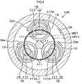
- Variateur de vitesse à rouleaux planétaires (105) selon la revendication 1, dans lequel :chacune des parties d'arbre (18) a une forme globalement cylindrique ; etune partie découpée (111) est formée au niveau de la partie côté arbre d'entrée d'une face périphérique extérieure de chacune des parties d'arbre (18), un rayon de la partie d'arbre (18) au niveau de la partie découpée (111) est plus court qu'un rayon de la partie d'arbre (18) au niveau de la partie autre que la partie découpée (111).
- Variateur de vitesse à rouleaux planétaires (5) selon la revendication 3, dans lequel :chacune des parties d'arbre (18) inclut un axe (16), et une bague (17) cylindrique ajustée de manière fixe sur l'axe ; etla partie découpée (111) est formée sur une face périphérique extérieure (17A) de la bague (17).
Applications Claiming Priority (1)
| Application Number | Priority Date | Filing Date | Title |
|---|---|---|---|
| JP2013257098A JP6300005B2 (ja) | 2013-12-12 | 2013-12-12 | 遊星ローラ式変速機 |
Publications (2)
| Publication Number | Publication Date |
|---|---|
| EP2913557A1 EP2913557A1 (fr) | 2015-09-02 |
| EP2913557B1 true EP2913557B1 (fr) | 2019-02-20 |
Family
ID=52023225
Family Applications (1)
| Application Number | Title | Priority Date | Filing Date |
|---|---|---|---|
| EP14196200.1A Active EP2913557B1 (fr) | 2013-12-12 | 2014-12-04 | Variateur de vitesse de rouleau planétaire |
Country Status (4)
| Country | Link |
|---|---|
| US (1) | US9239098B2 (fr) |
| EP (1) | EP2913557B1 (fr) |
| JP (1) | JP6300005B2 (fr) |
| CN (1) | CN104712719B (fr) |
Families Citing this family (9)
| Publication number | Priority date | Publication date | Assignee | Title |
|---|---|---|---|---|
| JP6604162B2 (ja) | 2015-11-25 | 2019-11-13 | 株式会社ジェイテクト | 遊星ローラ式変速機及びその組立方法並びにその取付方法 |
| JP6604160B2 (ja) * | 2015-11-25 | 2019-11-13 | 株式会社ジェイテクト | 遊星ローラ式変速機の組立装置及び組立方法 |
| JP6604161B2 (ja) * | 2015-11-25 | 2019-11-13 | 株式会社ジェイテクト | 遊星ローラ式変速機の組立方法 |
| JP6825326B2 (ja) | 2016-11-18 | 2021-02-03 | 株式会社ジェイテクト | 遊星ローラ式変速装置 |
| JP7112817B2 (ja) * | 2016-12-06 | 2022-08-04 | 株式会社ジェイテクト | 遊星ローラ式変速モータ |
| CA3089155A1 (fr) * | 2018-06-06 | 2019-12-12 | Vectis Drive Inc. | Entrainement a traction ou friction a rapport fixe |
| JP7206076B2 (ja) * | 2018-08-27 | 2023-01-17 | 積水化学工業株式会社 | 継手構造 |
| CN111795123A (zh) * | 2019-06-24 | 2020-10-20 | 北京稳力科技有限公司 | 适用于高输入转速的摩擦传动行星增速装置 |
| JP2022057875A (ja) * | 2020-09-30 | 2022-04-11 | 日本電産株式会社 | 減速装置 |
Family Cites Families (8)
| Publication number | Priority date | Publication date | Assignee | Title |
|---|---|---|---|---|
| GB585876A (en) * | 1944-06-28 | 1947-02-27 | George Waters | Improvements in and relating to friction gearing |
| US2815685A (en) * | 1954-03-25 | 1957-12-10 | Parrett John Thomas | Speed changing mechanism |
| JPS60157556A (ja) * | 1984-01-27 | 1985-08-17 | Koyo Seiko Co Ltd | 遊星ロ−ラ式動力伝達装置 |
| JPS6333055U (fr) | 1986-08-20 | 1988-03-03 | ||
| JP3383809B2 (ja) * | 1992-12-03 | 2003-03-10 | 光洋精工株式会社 | 遊星ローラ式動力伝達装置 |
| DK171047B1 (da) * | 1995-03-29 | 1996-04-29 | Anders Peter Kolstrup | Planetgear til høje omdrejningstal |
| JP2000257684A (ja) * | 1999-03-05 | 2000-09-19 | Nsk Ltd | 摩擦式変速機 |
| JP3834717B2 (ja) | 2001-11-26 | 2006-10-18 | 株式会社ジェイテクト | 遊星ローラ式変速機 |
-
2013
- 2013-12-12 JP JP2013257098A patent/JP6300005B2/ja active Active
-
2014
- 2014-12-04 EP EP14196200.1A patent/EP2913557B1/fr active Active
- 2014-12-09 US US14/564,428 patent/US9239098B2/en active Active
- 2014-12-11 CN CN201410766655.XA patent/CN104712719B/zh active Active
Non-Patent Citations (1)
| Title |
|---|
| None * |
Also Published As
| Publication number | Publication date |
|---|---|
| CN104712719A (zh) | 2015-06-17 |
| EP2913557A1 (fr) | 2015-09-02 |
| CN104712719B (zh) | 2018-12-21 |
| US20150167821A1 (en) | 2015-06-18 |
| JP6300005B2 (ja) | 2018-03-28 |
| US9239098B2 (en) | 2016-01-19 |
| JP2015113931A (ja) | 2015-06-22 |
Similar Documents
| Publication | Publication Date | Title |
|---|---|---|
| EP2913557B1 (fr) | Variateur de vitesse de rouleau planétaire | |
| EP2685129B1 (fr) | Mécanisme de réduction de vitesse et appareil de transmission de couple de moteur le comprenant | |
| EP2068038B1 (fr) | Engrenage de réduction | |
| EP2889509B1 (fr) | Variateur de vitesse à rouleaux planétaires | |
| JP6491456B2 (ja) | トラクション動力伝達装置 | |
| EP2644425A1 (fr) | Mécanisme de réduction de vitesse et dispositif de transmission de couple moteur comprenant le mécanisme de réduction de vitesse | |
| US11493112B2 (en) | Speed reducer | |
| US20120319539A1 (en) | Drive motor for electric vehicle | |
| JP5074292B2 (ja) | 減速機の出力部構造 | |
| CN112709787A (zh) | 减速器的壳体、减速器以及工业用机器人 | |
| JP2016080064A (ja) | トラクション動力伝達装置 | |
| JP4807150B2 (ja) | 不思議遊星ローラ式減速機 | |
| JP4798659B2 (ja) | 電動モータ付き車輪駆動装置 | |
| JP7187888B2 (ja) | 遊星式動力伝達装置 | |
| JP7551884B2 (ja) | 回転機器 | |
| US20250305560A1 (en) | Eccentric oscillating gear device | |
| WO2021105735A1 (fr) | Machine électrique rotative | |
| KR20150025165A (ko) | 속도-감소 변속 베어링 | |
| JP6863095B2 (ja) | 電動機 | |
| JPH044347A (ja) | 遊星ローラ式減速機 | |
| US20160053831A1 (en) | One-way clutch device | |
| JP6772774B2 (ja) | 遊星ローラ式変速モータ | |
| KR20160133722A (ko) | 내구성 향상과 소음 및 진동 저감을 위한 로봇 관절용 사이클로이드 기어 모터 및 이를 포함하는 로봇 | |
| JP2024142183A (ja) | 遊星ローラ式動力伝達装置 | |
| JP2017044232A (ja) | 遊星ローラ式の動力伝達装置 |
Legal Events
| Date | Code | Title | Description |
|---|---|---|---|
| PUAI | Public reference made under article 153(3) epc to a published international application that has entered the european phase |
Free format text: ORIGINAL CODE: 0009012 |
|
| AK | Designated contracting states |
Kind code of ref document: A1 Designated state(s): AL AT BE BG CH CY CZ DE DK EE ES FI FR GB GR HR HU IE IS IT LI LT LU LV MC MK MT NL NO PL PT RO RS SE SI SK SM TR |
|
| AX | Request for extension of the european patent |
Extension state: BA ME |
|
| 17P | Request for examination filed |
Effective date: 20160211 |
|
| RBV | Designated contracting states (corrected) |
Designated state(s): AL AT BE BG CH CY CZ DE DK EE ES FI FR GB GR HR HU IE IS IT LI LT LU LV MC MK MT NL NO PL PT RO RS SE SI SK SM TR |
|
| GRAP | Despatch of communication of intention to grant a patent |
Free format text: ORIGINAL CODE: EPIDOSNIGR1 |
|
| STAA | Information on the status of an ep patent application or granted ep patent |
Free format text: STATUS: GRANT OF PATENT IS INTENDED |
|
| INTG | Intention to grant announced |
Effective date: 20180830 |
|
| GRAS | Grant fee paid |
Free format text: ORIGINAL CODE: EPIDOSNIGR3 |
|
| GRAA | (expected) grant |
Free format text: ORIGINAL CODE: 0009210 |
|
| STAA | Information on the status of an ep patent application or granted ep patent |
Free format text: STATUS: THE PATENT HAS BEEN GRANTED |
|
| AK | Designated contracting states |
Kind code of ref document: B1 Designated state(s): AL AT BE BG CH CY CZ DE DK EE ES FI FR GB GR HR HU IE IS IT LI LT LU LV MC MK MT NL NO PL PT RO RS SE SI SK SM TR |
|
| REG | Reference to a national code |
Ref country code: GB Ref legal event code: FG4D |
|
| REG | Reference to a national code |
Ref country code: CH Ref legal event code: EP |
|
| REG | Reference to a national code |
Ref country code: DE Ref legal event code: R096 Ref document number: 602014041188 Country of ref document: DE |
|
| REG | Reference to a national code |
Ref country code: AT Ref legal event code: REF Ref document number: 1098604 Country of ref document: AT Kind code of ref document: T Effective date: 20190315 |
|
| REG | Reference to a national code |
Ref country code: IE Ref legal event code: FG4D |
|
| REG | Reference to a national code |
Ref country code: NL Ref legal event code: MP Effective date: 20190220 |
|
| REG | Reference to a national code |
Ref country code: LT Ref legal event code: MG4D |
|
| PG25 | Lapsed in a contracting state [announced via postgrant information from national office to epo] |
Ref country code: SE Free format text: LAPSE BECAUSE OF FAILURE TO SUBMIT A TRANSLATION OF THE DESCRIPTION OR TO PAY THE FEE WITHIN THE PRESCRIBED TIME-LIMIT Effective date: 20190220 Ref country code: NL Free format text: LAPSE BECAUSE OF FAILURE TO SUBMIT A TRANSLATION OF THE DESCRIPTION OR TO PAY THE FEE WITHIN THE PRESCRIBED TIME-LIMIT Effective date: 20190220 Ref country code: PT Free format text: LAPSE BECAUSE OF FAILURE TO SUBMIT A TRANSLATION OF THE DESCRIPTION OR TO PAY THE FEE WITHIN THE PRESCRIBED TIME-LIMIT Effective date: 20190620 Ref country code: LT Free format text: LAPSE BECAUSE OF FAILURE TO SUBMIT A TRANSLATION OF THE DESCRIPTION OR TO PAY THE FEE WITHIN THE PRESCRIBED TIME-LIMIT Effective date: 20190220 Ref country code: NO Free format text: LAPSE BECAUSE OF FAILURE TO SUBMIT A TRANSLATION OF THE DESCRIPTION OR TO PAY THE FEE WITHIN THE PRESCRIBED TIME-LIMIT Effective date: 20190520 Ref country code: FI Free format text: LAPSE BECAUSE OF FAILURE TO SUBMIT A TRANSLATION OF THE DESCRIPTION OR TO PAY THE FEE WITHIN THE PRESCRIBED TIME-LIMIT Effective date: 20190220 |
|
| PG25 | Lapsed in a contracting state [announced via postgrant information from national office to epo] |
Ref country code: IS Free format text: LAPSE BECAUSE OF FAILURE TO SUBMIT A TRANSLATION OF THE DESCRIPTION OR TO PAY THE FEE WITHIN THE PRESCRIBED TIME-LIMIT Effective date: 20190620 Ref country code: BG Free format text: LAPSE BECAUSE OF FAILURE TO SUBMIT A TRANSLATION OF THE DESCRIPTION OR TO PAY THE FEE WITHIN THE PRESCRIBED TIME-LIMIT Effective date: 20190520 Ref country code: HR Free format text: LAPSE BECAUSE OF FAILURE TO SUBMIT A TRANSLATION OF THE DESCRIPTION OR TO PAY THE FEE WITHIN THE PRESCRIBED TIME-LIMIT Effective date: 20190220 Ref country code: RS Free format text: LAPSE BECAUSE OF FAILURE TO SUBMIT A TRANSLATION OF THE DESCRIPTION OR TO PAY THE FEE WITHIN THE PRESCRIBED TIME-LIMIT Effective date: 20190220 Ref country code: LV Free format text: LAPSE BECAUSE OF FAILURE TO SUBMIT A TRANSLATION OF THE DESCRIPTION OR TO PAY THE FEE WITHIN THE PRESCRIBED TIME-LIMIT Effective date: 20190220 Ref country code: GR Free format text: LAPSE BECAUSE OF FAILURE TO SUBMIT A TRANSLATION OF THE DESCRIPTION OR TO PAY THE FEE WITHIN THE PRESCRIBED TIME-LIMIT Effective date: 20190521 |
|
| REG | Reference to a national code |
Ref country code: AT Ref legal event code: MK05 Ref document number: 1098604 Country of ref document: AT Kind code of ref document: T Effective date: 20190220 |
|
| PG25 | Lapsed in a contracting state [announced via postgrant information from national office to epo] |
Ref country code: IT Free format text: LAPSE BECAUSE OF FAILURE TO SUBMIT A TRANSLATION OF THE DESCRIPTION OR TO PAY THE FEE WITHIN THE PRESCRIBED TIME-LIMIT Effective date: 20190220 Ref country code: AL Free format text: LAPSE BECAUSE OF FAILURE TO SUBMIT A TRANSLATION OF THE DESCRIPTION OR TO PAY THE FEE WITHIN THE PRESCRIBED TIME-LIMIT Effective date: 20190220 Ref country code: SK Free format text: LAPSE BECAUSE OF FAILURE TO SUBMIT A TRANSLATION OF THE DESCRIPTION OR TO PAY THE FEE WITHIN THE PRESCRIBED TIME-LIMIT Effective date: 20190220 Ref country code: EE Free format text: LAPSE BECAUSE OF FAILURE TO SUBMIT A TRANSLATION OF THE DESCRIPTION OR TO PAY THE FEE WITHIN THE PRESCRIBED TIME-LIMIT Effective date: 20190220 Ref country code: DK Free format text: LAPSE BECAUSE OF FAILURE TO SUBMIT A TRANSLATION OF THE DESCRIPTION OR TO PAY THE FEE WITHIN THE PRESCRIBED TIME-LIMIT Effective date: 20190220 Ref country code: ES Free format text: LAPSE BECAUSE OF FAILURE TO SUBMIT A TRANSLATION OF THE DESCRIPTION OR TO PAY THE FEE WITHIN THE PRESCRIBED TIME-LIMIT Effective date: 20190220 Ref country code: CZ Free format text: LAPSE BECAUSE OF FAILURE TO SUBMIT A TRANSLATION OF THE DESCRIPTION OR TO PAY THE FEE WITHIN THE PRESCRIBED TIME-LIMIT Effective date: 20190220 Ref country code: RO Free format text: LAPSE BECAUSE OF FAILURE TO SUBMIT A TRANSLATION OF THE DESCRIPTION OR TO PAY THE FEE WITHIN THE PRESCRIBED TIME-LIMIT Effective date: 20190220 |
|
| REG | Reference to a national code |
Ref country code: DE Ref legal event code: R097 Ref document number: 602014041188 Country of ref document: DE |
|
| PG25 | Lapsed in a contracting state [announced via postgrant information from national office to epo] |
Ref country code: SM Free format text: LAPSE BECAUSE OF FAILURE TO SUBMIT A TRANSLATION OF THE DESCRIPTION OR TO PAY THE FEE WITHIN THE PRESCRIBED TIME-LIMIT Effective date: 20190220 Ref country code: PL Free format text: LAPSE BECAUSE OF FAILURE TO SUBMIT A TRANSLATION OF THE DESCRIPTION OR TO PAY THE FEE WITHIN THE PRESCRIBED TIME-LIMIT Effective date: 20190220 |
|
| PLBE | No opposition filed within time limit |
Free format text: ORIGINAL CODE: 0009261 |
|
| STAA | Information on the status of an ep patent application or granted ep patent |
Free format text: STATUS: NO OPPOSITION FILED WITHIN TIME LIMIT |
|
| PG25 | Lapsed in a contracting state [announced via postgrant information from national office to epo] |
Ref country code: AT Free format text: LAPSE BECAUSE OF FAILURE TO SUBMIT A TRANSLATION OF THE DESCRIPTION OR TO PAY THE FEE WITHIN THE PRESCRIBED TIME-LIMIT Effective date: 20190220 |
|
| 26N | No opposition filed |
Effective date: 20191121 |
|
| PG25 | Lapsed in a contracting state [announced via postgrant information from national office to epo] |
Ref country code: SI Free format text: LAPSE BECAUSE OF FAILURE TO SUBMIT A TRANSLATION OF THE DESCRIPTION OR TO PAY THE FEE WITHIN THE PRESCRIBED TIME-LIMIT Effective date: 20190220 |
|
| PG25 | Lapsed in a contracting state [announced via postgrant information from national office to epo] |
Ref country code: TR Free format text: LAPSE BECAUSE OF FAILURE TO SUBMIT A TRANSLATION OF THE DESCRIPTION OR TO PAY THE FEE WITHIN THE PRESCRIBED TIME-LIMIT Effective date: 20190220 |
|
| REG | Reference to a national code |
Ref country code: CH Ref legal event code: PL |
|
| REG | Reference to a national code |
Ref country code: BE Ref legal event code: MM Effective date: 20191231 |
|
| PG25 | Lapsed in a contracting state [announced via postgrant information from national office to epo] |
Ref country code: MC Free format text: LAPSE BECAUSE OF FAILURE TO SUBMIT A TRANSLATION OF THE DESCRIPTION OR TO PAY THE FEE WITHIN THE PRESCRIBED TIME-LIMIT Effective date: 20190220 |
|
| GBPC | Gb: european patent ceased through non-payment of renewal fee |
Effective date: 20191204 |
|
| PG25 | Lapsed in a contracting state [announced via postgrant information from national office to epo] |
Ref country code: FR Free format text: LAPSE BECAUSE OF NON-PAYMENT OF DUE FEES Effective date: 20191231 Ref country code: IE Free format text: LAPSE BECAUSE OF NON-PAYMENT OF DUE FEES Effective date: 20191204 Ref country code: LU Free format text: LAPSE BECAUSE OF NON-PAYMENT OF DUE FEES Effective date: 20191204 Ref country code: GB Free format text: LAPSE BECAUSE OF NON-PAYMENT OF DUE FEES Effective date: 20191204 |
|
| PG25 | Lapsed in a contracting state [announced via postgrant information from national office to epo] |
Ref country code: LI Free format text: LAPSE BECAUSE OF NON-PAYMENT OF DUE FEES Effective date: 20191231 Ref country code: BE Free format text: LAPSE BECAUSE OF NON-PAYMENT OF DUE FEES Effective date: 20191231 Ref country code: CH Free format text: LAPSE BECAUSE OF NON-PAYMENT OF DUE FEES Effective date: 20191231 |
|
| PG25 | Lapsed in a contracting state [announced via postgrant information from national office to epo] |
Ref country code: CY Free format text: LAPSE BECAUSE OF FAILURE TO SUBMIT A TRANSLATION OF THE DESCRIPTION OR TO PAY THE FEE WITHIN THE PRESCRIBED TIME-LIMIT Effective date: 20190220 |
|
| PG25 | Lapsed in a contracting state [announced via postgrant information from national office to epo] |
Ref country code: HU Free format text: LAPSE BECAUSE OF FAILURE TO SUBMIT A TRANSLATION OF THE DESCRIPTION OR TO PAY THE FEE WITHIN THE PRESCRIBED TIME-LIMIT; INVALID AB INITIO Effective date: 20141204 Ref country code: MT Free format text: LAPSE BECAUSE OF FAILURE TO SUBMIT A TRANSLATION OF THE DESCRIPTION OR TO PAY THE FEE WITHIN THE PRESCRIBED TIME-LIMIT Effective date: 20190220 |
|
| PG25 | Lapsed in a contracting state [announced via postgrant information from national office to epo] |
Ref country code: MK Free format text: LAPSE BECAUSE OF FAILURE TO SUBMIT A TRANSLATION OF THE DESCRIPTION OR TO PAY THE FEE WITHIN THE PRESCRIBED TIME-LIMIT Effective date: 20190220 |
|
| PGFP | Annual fee paid to national office [announced via postgrant information from national office to epo] |
Ref country code: DE Payment date: 20251028 Year of fee payment: 12 |