EP2918525B1 - Vorrichtung zum enthaaren von gegenständen, die auf einer halterung gelagert werden, und entsprechende vorrichtung - Google Patents
Vorrichtung zum enthaaren von gegenständen, die auf einer halterung gelagert werden, und entsprechende vorrichtung Download PDFInfo
- Publication number
- EP2918525B1 EP2918525B1 EP15159041.1A EP15159041A EP2918525B1 EP 2918525 B1 EP2918525 B1 EP 2918525B1 EP 15159041 A EP15159041 A EP 15159041A EP 2918525 B1 EP2918525 B1 EP 2918525B1
- Authority
- EP
- European Patent Office
- Prior art keywords
- sensor
- mark
- objects
- stack
- bags
- Prior art date
- Legal status (The legal status is an assumption and is not a legal conclusion. Google has not performed a legal analysis and makes no representation as to the accuracy of the status listed.)
- Active
Links
Images


Classifications
-
- B—PERFORMING OPERATIONS; TRANSPORTING
- B65—CONVEYING; PACKING; STORING; HANDLING THIN OR FILAMENTARY MATERIAL
- B65G—TRANSPORT OR STORAGE DEVICES, e.g. CONVEYORS FOR LOADING OR TIPPING, SHOP CONVEYOR SYSTEMS OR PNEUMATIC TUBE CONVEYORS
- B65G59/00—De-stacking of articles
-
- B—PERFORMING OPERATIONS; TRANSPORTING
- B65—CONVEYING; PACKING; STORING; HANDLING THIN OR FILAMENTARY MATERIAL
- B65G—TRANSPORT OR STORAGE DEVICES, e.g. CONVEYORS FOR LOADING OR TIPPING, SHOP CONVEYOR SYSTEMS OR PNEUMATIC TUBE CONVEYORS
- B65G59/00—De-stacking of articles
- B65G59/02—De-stacking from the top of the stack
- B65G59/04—De-stacking from the top of the stack by suction or magnetic devices
- B65G59/045—De-stacking from the top of the stack by suction or magnetic devices with a stepwise upward movement of the stack
Definitions
- the present invention relates to a method for depiling objects such as bags or blanks of cardboard boxes stored on a support and to an associated device.
- the present invention relates more specifically to the supply station empty bags of a bagging chain.
- a bag consists of an envelope of flexible material forming a tube whose one end, the bottom, is closed, while the other end is open prior to filling and is closed after the filling.
- the envelope may be made from at least one sheet or complex of sheets of various materials, for example paper, cotton, plastic or other.
- the bags are manufactured on a first site and then are filled on a second site.
- the first site can also be printed so as to affix on the sides of the bags the appropriate information relating to the product that will be packaged there.
- the bags are stored according to a palletizing plan (hereinafter referred to as a storage plan) on pallets in order to be transferred to the filling site.
- a palletizing plan hereinafter referred to as a storage plan
- the bags come out of the production and printing line one after the other, all oriented in the same way.
- the bags 10 are then grouped together in stacks 12 which are grouped in layers 14, the layers being stacked on each other on a support 16 such as a pallet.
- the bags of the same pile are all oriented in the same way.
- batteries all include the same number of bags.
- the stacks 12 of one and the same layer are not all oriented in the same way, so that the bags from one stack to another are not oriented in the same way.
- the batteries 12 are not arranged in the same way.
- the formation of a pallet of bags is automated and performed by a controller that respects a storage plan.
- the bags must be introduced one after another and must imperatively all be oriented in the same way.
- a feeding station of a bagging chain comprises an automaton capable of grasping a bag at the level of the pallet of bags, of the transfer to the bagging chain, taking care to orient it correctly.
- the automaton knows in theory the position of each bag of the pallet and should therefore be able to correctly capture each bag and deposit it correctly oriented at the level of the bagging chain according to a destocking plan.
- the destocking plan can not be applied.
- the destocking plan is not applied and the controller comprises at the gripper a camera for filming the top of the pallet bags, an image recognition software to determine the position of the bags and their orientations.
- the camera captures an image from the top of the pallet. This image is then analyzed by the recognition software image to determine the position of a bag to enter and its orientation. Since the position of the bag is known, the automaton determines its trajectory to come straight up to the bag to be grasped, seize it and then transport it to the bagging chain, having taken care eventually to modify its orientation if necessary.
- the image recognition software is relatively complex to set and require that the captured image is as regular as possible in terms of rendering.
- the rendering of the images is not regular, the surrounding light varies according to particular hours of the day, the bags reflecting more or less this light depending on the material used to make them.
- this procedure requiring an image analysis can not be implemented.
- image recognition software is relatively expensive.
- US 2013/0096713 A1 discloses a method according to the preamble of claim 1.
- the present invention aims to overcome the disadvantages of the prior art.
- the subject of the invention is a method of unstacking objects stored according to several stacks, each stack comprising several objects, said objects being oriented in the same manner in each stack, said unstacking method consisting in grasping by means of at least one gripper, controlled by a control system, one by one the objects in order to deposit them in a given orientation at an outlet, each object comprising at least one mark positioned identically for all the objects, characterized in that the method comprises using mark detection means comprising at least a first sensor configured to detect a variation of a physical quantity when a mark goes into its measuring field, moving said first sensor along a secant path with the theoretical position of the mark of the object of the stack being unstacked to determine if the stack being unstacked is complete.
- the invention also relates to a feeding station according to claim 6.
- bags 10 are shown stored on a support 16, for example a pallet.
- Bags 10 are stored flat. They are grouped by batteries 12 which are grouped in layers 14, the layers being stacked on each other on the support 16.
- each bag 10 comprises a bottom 18, an opening 20 and a longitudinal axis 22 perpendicular to the edges delimiting the bottom and the opening.
- a device 24 for unstacking bags 10 which comprises an unstacking zone 26 at which is positioned a support 16 and an outlet 28 at which the bags are unstacked and are positioned in a given orientation.
- the output of the device 24 corresponds to the bag feeding of a bagging chain materialized by a roller conveyor 30.
- the bags 10 are all oriented in the same manner.
- the orientation of a bag is characterized by the direction of its longitudinal axis 22 and the direction of the bag, namely the position of the opening 20 relative to the bottom 18 along the longitudinal axis 22.
- the longitudinal axis 22 each bag must be parallel to an exit direction marked by an arrow 32 on the figure 5 and the opening 20 positioned in an exit direction shown by the arrow 32, the opening 20 being positioned at the head of the boom 32 and the bottom 18 at the tail of the boom 32.
- the exit direction may be parallel or perpendicular to the direction of travel of the bags at the exit.
- the exit direction 32 is perpendicular to the traveling direction 36.
- each layer 14 of stacks 12 of bags comprises three stacks 12.
- Each stack 12 comprises a theoretical number N of bags 10.
- each layer 14 comprises four stacks of bags.
- the bags are stored on the support according to a storage plan.
- the positioning and orientation of the bags are defined with respect to an orthonormal coordinate system X 0, Y 0, Z 0 of the storage plan.
- the support 16 comprises a planar top surface (on which the bags are stacked) which corresponds to the plane X 0 Y 0 , the direction Z 0 being perpendicular to this upper surface of the support 16.
- the upper surface is square or rectangular, the X 0 direction being parallel to certain edges of the upper surface and the Y 0 direction parallel to other edges.
- the edges of the bags are parallel to the edges of the upper surface of the support 16, the edges of the bags are parallel to the axis X 0 or Y 0 .
- the bags of the same pile are all oriented in the same way and the number of bags per stack is theoretically identical.
- the destocking plan corresponds to the storage plan, only the gripping order of the bags being reversed.
- the bags are positioned and oriented according to a reference identical to the reference X 0 , Y 0 , Z 0 of the storage plan.
- the unstacking device 24 comprises at least one gripper 38 configured to move in a reference X 1 , Y 1 , Z 1 of the unstacking device.
- the direction X 1 is arranged in a plane parallel to the plane of depositing the bags and parallel to the direction of travel 36.
- the direction Y 1 is arranged in a plan of deposit of the bags and perpendicular to the direction of Scrolling 36.
- the plane of removal of the bags corresponds to the horizontal plane.
- the direction Z 1 corresponds to the vertical direction.
- the unstacking zone 26 comprises a flat deposition surface 40 on which is placed a support 16 which is preferably arranged in a plane X 1 Y 1 , ie horizontally.
- the gripper 38 depilates the bags by applying the destocking plan.
- it comprises means for determining the position of the coordinate system X 0 , Y 0 , Z 0 of the storage plane in the X 1 , Y 1 , Z 1 reference of the unstacking device.
- the upper surface of the support 16 and the deposition surface 40 are parallel so that the Z 0 and Z 1 axes are parallel.
- the unstacking device comprises means for positioning the carrier so that the X 0 axis is parallel to the axis X 1 or Y 1.
- the unstacking device may comprise a polarizer so that the axis X 0 is parallel to the axis X 1 .
- the means for determining the position of the coordinate system X 0 , Y 0 , Z 0 of the storage plane in the X 1 , Y 1 , Z 1 coordinate system of the unstacking device comprise means 42 for detecting a mark on a bag.
- each bag 10 comprises at least one mark 44. All the bags of the same pallet comprise the same or the same marks.
- the mark 44 is in the form of a marker whose color provides a color contrast with the rest of the bag.
- the mark or marks 44 are positioned on the bag so as to identify the orientation of the bag.
- the bag 10 comprises a mark longer than wide, for example rectangular and the angle formed by the direction of the mark L44 corresponding to its length and the longitudinal axis 22 is constant from one bag to another.
- the direction of the mark L44 is perpendicular to the longitudinal axis 22.
- the mark 44 has a width of 1 to 2 cm and a length of the order of 5 to 15 cm.
- the bag comprises two marks 44, preferably identical (square according to the example shown), offset in an offset direction and the angle formed by the offset direction and the longitudinal axis 22 is constant from a bag to the 'other.
- the offset direction is parallel to the longitudinal axis 22.
- the offset direction of the two marks 44 is perpendicular to the longitudinal axis 22.
- each bag comprises at least one fold line 45 allowing the head of the bag to be folded and glued after filling the bag so as to close it.
- the mark or marks 44 is or are arranged between the edge 47 of the opening 20 and the fold line 45.
- the mark or marks 44 are not positioned in the middle position relative to the bottom 18 and the opening 20.
- the mark or marks are arranged near the opening 20. In this case, when the bag is folded to close the opening, the mark or marks are no longer visible after closing the bag.
- the detection means 42 take an image of the top of the support 16 on which the bags are stacked.
- this image is analyzed to determine the position of the X 0 , Y 0 , Z 0 coordinate of the storage plane in the X 1 , Y 1 , Z 1 coordinate system as a function of the position of the marks.
- the image is compared with a reference image in order to determine the angular offset between the reference X 0 , Y 0 , Z 0 of the storage plane and the reference X 1 Y 1 Z 1 of the unstacking device, the axes Zo and Z 1 being parallel.
- the unstacking device can apply the destocking plan taking into account this angular offset to correctly orient the bags.
- the method uses only one image analysis at the beginning of the process. By following, he can apply the destocking plan and does not need to make an image analysis with each bag entered. According to another advantage, the analysis of the image is simplified insofar as it is easier to identify on an image marks with a high color contrast compared to the rest of the bag that bag edges and openings.
- the detection means 42 are in the form of a mobile sensor 46 of mark detection and capable of moving along at least one direction of movement, in particular in the direction X 1 or Y 1 . This movement determines the position of the marks 44 according to the direction of travel.
- the detection sensor 46 is integral with the gripper 38.
- the unstacking device further comprises means for comparing the position of the marks 44 recorded by the detection sensor 46 and the position of the marks 44 in the retrieval plane to determine the angular offset between the X 0 , Y 0 , Z mark. 0 of the storage plan and the X 1 mark, Y 1 , Z 1 of the unstacking device, the Z 0 and Z 1 axes being parallel.
- the unstacking device can apply the destocking plan taking into account this angular offset to correctly orient the bags.
- the unstacking device comprises a control system.
- This control system comprises at least one memory and calculation means.
- the storage plan is stored in the memory of the control system and the latter is configured to control the movements of the gripper (s) to ensure the unstacking of the carrier bags according to the storage plan.
- the unstacking device described above ensures reliable unstacking when the number of bags of each stack is in line with that of the destocking plan.
- the mark detection means comprise at least one sensor 46 movable above the bags, and more particularly above the stack of bags being unstacked.
- the sensor 46 moves so that its trajectory is secant with said position.
- the control system controls the movements of the sensor 46.
- the sensor 46 is secured to a mobile independent of a gripper 38.
- the sensor 46 is connected to the gripper 38.
- the senor 46 By moving in a plane parallel to the surface of the bag at which the mark is affixed, the sensor 46 is configured to detect a variation of a physical quantity when the mark 44 passes into its measurement field.
- the sensor 46 comprises a transmitter of a signal and a receiver of said signal.
- the receiver receives a signal emitted by the transmitter which is different from that received when the mark 44 is outside the measuring field.
- the sensor 46 is a light sensor and the mark 44 is a mark with a large color contrast relative to the rest of the surface of the bag on which it is affixed.
- Other couples sensor / brand can be considered.
- the sensor may be of the electromagnetic type and the mark may be of a material adapted to modify an electromagnetic field.
- the sensor 46 transmits information to the control system when the mark is in its measurement field.
- control system controls the gripper so that the gripper seizes the bags one by one according to the storage plan.
- the sensor 46 moves over the bags. Its trajectory is determined by the control system so that said trajectory is secant with the theoretical position of the mark affixed to each of the bags of the stack being unstacked.
- the control system knowing the position of the sensor 46 at the time of detection of the mark determines the position of the mark detected.
- the position of the detected mark is not identical to the theoretical position of the mark of a bag of the stack being unstacked, it means that the pile being unstacked is finished and that the control system can control the gripper so that it unstacks the next stack.
- the detection of the actual position of a mark is carried out only near the end of each stack.
- the measurement field of the sensor is disposed below and vertically of the sensor 46.
- the mark is detected when it is directly above the sensor 46.
- the sensor 46 When the sensor 46 is secured to the gripper 38, it is positioned on the gripper so that its measuring field does not interfere with the bag gripped by the gripper. When the measurement field of the sensor is disposed under and vertically of the sensor 46, the latter is shifted outwardly with respect to the plumb with the edges of the bag gripped by the gripper 38. In addition, the sensor 46 is positioned on the gripper so that during the movement of the gripper 38 of the stack being unstacked to the output, said sensor passes in line with the theoretical position of the mark of the bag of the stack being unstacked.
- the unstacking device comprises a first sensor 46 as previously described and a second sensor 46 'provided to refine the position of the gripper relative to the next bag to capture.
- the sensors 46, 46 ' are offset by a constant distance in a plane parallel to the surface of the bags to be unstacked.
- the two sensors 46, 46 ' are identical.
- the two sensors 46, 46 ' are integral with the gripper 38.
- each bag is grasped so that the second sensor 46 'is disposed in line with the mark of the bag seized.
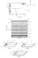
- the gripper 38 shifts in the detection direction 48. If the first sensor 46 detects a mark 44, it means that the stack is not complete as shown in FIG. Figure 6B . If the first sensor 46 does not detect a mark 44, it means that the stack is complete and the gripper 38 can unstack the next stack.
- the gripper follows the destocking plan by adapting the number of bags per stack according to the information transmitted by the sensors 46,46 '.
- the unstacking device comprises a gripper 38 connected to a robot 50 cartesian allowing the gripper 38 to move in the directions X 1 and Y 1 , in a horizontal plane above the objects
- first elevator 52 for lifting the support 16
- second elevator 54 with a platform 56 on which are piled up the unstacked bags, oriented correctly, as well as means for controlling the movements of the two elevators 52 and 56.
- the gripper 38 is configured to move along only the directions X 1 and Y 1 .
- the positions of the elevators are determined according to the bag gripped by the gripper, the first elevator being positioned to allow the gripper to grip the bag and the second elevator being positioned so that the gripped bag can be grasped. arranged on the stack of unstacked bags. In this case, the position of each elevator is adjusted almost to each bag.
- the gripper 38 is configured to move in the directions X 1 and Y 1 and on a short stroke in the direction Z 1 , the small stroke corresponding to the height of a stack. In this case, the position of each elevator is adjusted at each layer change.
- the device of the invention can be used to depilate other objects stacked according to a storage plan, for example blanks of cardboard boxes stored as the empty bags in several layers, each comprising several stacks, each stack comprising several blanks stacked on each other and all oriented in the same manner for each stack.
- the pallet can be replaced by any other medium.
Landscapes
- Sheets, Magazines, And Separation Thereof (AREA)
- Supplying Of Containers To The Packaging Station (AREA)
Claims (11)
- Verfahren zum Entstapeln von in mehreren Stapeln gelagerten Gegenständen, wobei jeder Stapel mehrere Gegenstände umfasst und die Gegenstände in jedem Stapel auf gleiche Weise ausgerichtet sind und wobei das Verfahren zum Entstapeln darin besteht, mittels wenigstens eines Greifers (38), der von einer Steuervorrichtung gesteuert ist, die Gegenstände nacheinander aufzunehmen, um diese im Bereich eines Ausgangs (38) in einer bestimmten Ausrichtung abzulegen, wobei jeder Gegenstand wenigstens eine Kennung (44) aufweist, die bei allen Gegenständen auf identische Weise positioniert ist, dadurch gekennzeichnet, dass das Verfahren darin besteht, Mittel zum Erfassen der Kennungen (44) zu verwenden, die wenigstens einen ersten Sensor (46) aufweisen, der dazu eingerichtet ist, die Änderung einer physikalischen Größe zu erfassen, wenn die Kennung (44) in sein Messfeld gelangt, und den ersten Sensor (46) entlang einer Bahn zu bewegen, die sich mit der theoretischen Position der Kennung des Gegenstands des aktuell entstapelten Stapels schneidet, um zu bestimmen, ob der aktuell entstapelte Stapel beendet ist.
- Verfahren nach Anspruch 1, dadurch gekennzeichnet, dass der erste Sensor (46) ein Lichtsensor ist und dass die Kennung (44) eine Kennung ist, die zur restlichen Oberfläche des Gegenstands, auf der diese angebracht ist, einen Farbkontrast aufweist.
- Verfahren nach Anspruch 1 oder 2, dadurch gekennzeichnet, dass die Steuervorrichtung die Bewegung des Greifers (38) in Abhängigkeit von einem Lagerplan der Gegenstände bestimmt, der mehrere Schichten umfasst, wobei jede Schicht mehrere Stapel umfasst.
- Verfahren nach Anspruch 3, dadurch gekennzeichnet, dass dieses darin besteht, einen Winkelversatz zwischen einer Markierung des Lagerplans und einer Markierung der Entstapelvorrichtung zu bestimmen.
- Verfahren nach Anspruch 4, dadurch gekennzeichnet, dass dieses darin besteht, die Kennungen (44) der Gegenstände und den ersten Sensor (46) dazu zu verwenden, den Winkelversatz zu bestimmen.
- Zufuhreinrichtung für eine Verpackungskette mit:- Gegenständen und einer Halterung (16), auf der die Gegenstände in mehreren Stapeln gelagert sind, wobei jeder Stapel mehrere Gegenstände umfasst und die Gegenstände in jedem Stapel auf gleiche Weise ausgerichtet sind und wobei jeder Gegenstand wenigstens eine Kennung (44) aufweist, die auf allen Gegenständen auf identische Weise positioniert ist- einer Vorrichtung zum Entstapeln von Gegenständen mit wenigstens einem Greifer (38), der von einer Steuervorrichtung gesteuert ist, um auf diese Weise Gegenstände nacheinander aufzunehmen und sie mit einer bestimmten Ausrichtung im Bereich eines Ausgangs (38) abzulegen,dadurch gekennzeichnet, dass die Vorrichtung wenigstens einen ersten Sensor (46) aufweist, der am Greifer (38) angebracht ist und auf dem Greifer derart positioniert ist, dass sein Messfeld nicht mit dem vom Greifer aufgenommenen Gegenstand wechselwirkt, wobei der erste Sensor (46) dazu eingerichtet ist, eine Änderung einer physikalischen Größe zu erfassen, wenn die Kennung (44) in sein Messfeld gelangt, und wobei der erste Sensor (46) entlang einer Bahn bewegbar ist, die sich mit der theoretischen Position der Kennung des Gegenstands des aktuell entstapelten Stapels schneidet, um über die Steuervorrichtung zu bestimmen, ob der aktuell entstapelte Stapel beendet ist.
- Zufuhreinrichtung einer Verpackungskette nach Anspruch 6, dadurch gekennzeichnet, dass der erste Sensor (46) ein Lichtsensor ist, wobei bei jedem Gegenstand die Kennung (44) einen Farbkontrast bezüglich der restlichen Oberfläche des Gegenstands aufweist, auf der diese angebracht ist.
- Zufuhreinrichtung einer Verpackungskette nach Anspruch 6 oder 7, dadurch gekennzeichnet, dass das Messfeld des Sensors (46) in senkrechter Richtung unter dem Sensor (46) angeordnet ist.
- Zufuhreinrichtung einer Verpackungskette nach einem der Ansprüche 6 bis 8, dadurch gekennzeichnet, dass diese einen zweiten Sensor (46') aufweist, der dazu vorgesehen ist, die Position des Greifers bezüglich des aufzunehmenden Gegenstands zu verbessern.
- Zufuhreinrichtung einer Verpackungskette nach Anspruch 9, dadurch gekennzeichnet, dass der zweite Sensor (46') bezüglich des ersten Sensors (46) in eine Erfassungsrichtung (48) versetzt ist, die sich mit der theoretischen Position der Kennung des Sacks des aktuell entstapelten Stapels schneidet.
- Zufuhreinrichtung einer Verpackungskette nach einem der Ansprüche 6 bis 10, dadurch gekennzeichnet, dass diese einen Roboter (50) aufweist, an dem der Greifer (38) angebracht ist, wobei der Roboter dazu eingerichtet ist, dass sich der Greifer (38) in einer horizontalen Ebene oberhalb der Gegenstände bewegt, und eine erste Hebebühne (52) aufweist, die es gestattet, eine Halterung (16), auf der die zu entstapelnden Gegenstände gelagert sind, anzuheben, und eine zweite Hebebühne (54) mit einer Plattform (56) aufweist, auf der die richtig ausgerichteten Säcke aufgestapelt werden, und Mittel aufweist, um die Bewegungen der beiden Hebebühnen (52, 56) zu steuern.
Applications Claiming Priority (1)
| Application Number | Priority Date | Filing Date | Title |
|---|---|---|---|
| FR1452095A FR3018511B1 (fr) | 2014-03-13 | 2014-03-13 | Procede pour depiler des objets stockes sur un support et dispositif associe |
Publications (2)
| Publication Number | Publication Date |
|---|---|
| EP2918525A1 EP2918525A1 (de) | 2015-09-16 |
| EP2918525B1 true EP2918525B1 (de) | 2016-10-05 |
Family
ID=50624824
Family Applications (1)
| Application Number | Title | Priority Date | Filing Date |
|---|---|---|---|
| EP15159041.1A Active EP2918525B1 (de) | 2014-03-13 | 2015-03-13 | Vorrichtung zum enthaaren von gegenständen, die auf einer halterung gelagert werden, und entsprechende vorrichtung |
Country Status (3)
| Country | Link |
|---|---|
| EP (1) | EP2918525B1 (de) |
| ES (1) | ES2610019T3 (de) |
| FR (1) | FR3018511B1 (de) |
Families Citing this family (1)
| Publication number | Priority date | Publication date | Assignee | Title |
|---|---|---|---|---|
| CN120097112B (zh) * | 2025-05-08 | 2025-09-23 | 江中药业股份有限公司 | 一种智能化药品产品码垛控制方法及系统 |
Family Cites Families (6)
| Publication number | Priority date | Publication date | Assignee | Title |
|---|---|---|---|---|
| JPH06255788A (ja) * | 1993-03-03 | 1994-09-13 | Mazda Motor Corp | 積み重ねワークの取出装置 |
| JPH08168984A (ja) * | 1994-10-18 | 1996-07-02 | Nippon Steel Corp | 直方体ワークの位置検出方法及び位置検出装置 |
| JPH1120948A (ja) * | 1997-07-07 | 1999-01-26 | Okuma Mach Works Ltd | ワーク搬送制御装置 |
| JP3849633B2 (ja) * | 2002-11-06 | 2006-11-22 | 株式会社ダイフク | 物品群の積み付け組み様式の認識方法および装置ならびに認識装置を具備した物品移載設備 |
| JP4911341B2 (ja) * | 2006-03-24 | 2012-04-04 | 株式会社ダイフク | 物品移載装置 |
| US9067744B2 (en) * | 2011-10-17 | 2015-06-30 | Kabushiki Kaisha Yaskawa Denki | Robot system, robot, and sorted article manufacturing method |
-
2014
- 2014-03-13 FR FR1452095A patent/FR3018511B1/fr not_active Expired - Fee Related
-
2015
- 2015-03-13 EP EP15159041.1A patent/EP2918525B1/de active Active
- 2015-03-13 ES ES15159041.1T patent/ES2610019T3/es active Active
Also Published As
| Publication number | Publication date |
|---|---|
| EP2918525A1 (de) | 2015-09-16 |
| ES2610019T3 (es) | 2017-04-25 |
| FR3018511B1 (fr) | 2016-07-01 |
| FR3018511A1 (fr) | 2015-09-18 |
Similar Documents
| Publication | Publication Date | Title |
|---|---|---|
| FR2957905A1 (fr) | Procede et dispositif de transfert de decoupes pour boites d'emballage | |
| EP3256268B1 (de) | Postsortiermaschine mit einer einen roboterarm umfassenden zufuhr und einem geneigtem flachförderer | |
| EP2551222B1 (de) | Verfahren zur Beförderung von Produkten, insbesondere von Lebensmitteltranchen | |
| EP2895412B1 (de) | Palettierverfahren und vorrichtung zur durchführung des verfahrens | |
| EP2809585B1 (de) | Verpackungsbehälter mit zentrierlasche, zuschnitte sowie satz von zuschnitten, verfahren und vorrichtung zur herstellung solcher verpackungsbehälter | |
| FR2976561A1 (fr) | Distributeur de flancs a plat. | |
| EP3112302B1 (de) | Vorrichtung und methode zum befüllen eines lagers | |
| EP2408698B1 (de) | Ladestation für plattenelemente und maschine zur bearbeitung solcher elemente | |
| EP3033223B1 (de) | Verfahren und vorrichtung zur anbringung von verstärkungen an einem kartonverpackungszuschnitt | |
| EP3227189B1 (de) | Vorrichtung und verfahren zum stapeln von verpackungen unterschiedlicher grössen | |
| FR2998284A1 (fr) | Dispositif et procede de placement d'une decoupe pour boites d'emballages avec depilage vertical et tapis de transfert. | |
| FR2986510A1 (fr) | Dispositif et procede de formation de boites d'emballages avec depilage vertical | |
| WO2017060597A1 (fr) | Procede et dispositif de manipulation de charge, appele colis | |
| WO2015197199A1 (fr) | Procede pour alimenter une machine avec des elements en plaque, station d'alimentation et machine de traitement ainsi equipee | |
| EP2918525B1 (de) | Vorrichtung zum enthaaren von gegenständen, die auf einer halterung gelagert werden, und entsprechende vorrichtung | |
| EP1854596A1 (de) | Vorrichtung zum Aufschneiden von Lebensmittelprodukten und daran angebundene Verpackungsmaschine | |
| FR3060547A1 (fr) | Appareil et procede de transfert, vers une ligne de traitement, d'imprimes initialement conditionnes en liasse | |
| FR3125452A1 (fr) | Outil de préhension de caisse et système de palettisation et/ou de dépalettisation le comprenant | |
| EP4051609A1 (de) | Vorrichtung und verfahren zum palettieren und entpalettieren | |
| EP3450028B1 (de) | Vorrichtung und verfahren zum sortieren von schachteln | |
| FR3060538A1 (fr) | Procede et appareil pour sectionner un lien entourant une liasse d'imprimes provenant d'une palette | |
| WO2009053543A1 (fr) | Systeme de depose de documents dans des caisses | |
| FR2494213A1 (fr) | Dispositif pour emballer des piles de papier dans des cartons preformes | |
| WO2017072428A1 (fr) | Dispositif et methode d'extraction | |
| EP2363281A1 (de) | Maschine zum Bekleiden das Innere von Verpackungskartons mit Plastiksäcken |
Legal Events
| Date | Code | Title | Description |
|---|---|---|---|
| PUAI | Public reference made under article 153(3) epc to a published international application that has entered the european phase |
Free format text: ORIGINAL CODE: 0009012 |
|
| AK | Designated contracting states |
Kind code of ref document: A1 Designated state(s): AL AT BE BG CH CY CZ DE DK EE ES FI FR GB GR HR HU IE IS IT LI LT LU LV MC MK MT NL NO PL PT RO RS SE SI SK SM TR |
|
| AX | Request for extension of the european patent |
Extension state: BA ME |
|
| 17P | Request for examination filed |
Effective date: 20160212 |
|
| RBV | Designated contracting states (corrected) |
Designated state(s): AL AT BE BG CH CY CZ DE DK EE ES FI FR GB GR HR HU IE IS IT LI LT LU LV MC MK MT NL NO PL PT RO RS SE SI SK SM TR |
|
| GRAP | Despatch of communication of intention to grant a patent |
Free format text: ORIGINAL CODE: EPIDOSNIGR1 |
|
| RIC1 | Information provided on ipc code assigned before grant |
Ipc: B65G 59/00 20060101ALI20160524BHEP Ipc: B65G 59/04 20060101AFI20160524BHEP |
|
| INTG | Intention to grant announced |
Effective date: 20160614 |
|
| GRAS | Grant fee paid |
Free format text: ORIGINAL CODE: EPIDOSNIGR3 |
|
| GRAA | (expected) grant |
Free format text: ORIGINAL CODE: 0009210 |
|
| AK | Designated contracting states |
Kind code of ref document: B1 Designated state(s): AL AT BE BG CH CY CZ DE DK EE ES FI FR GB GR HR HU IE IS IT LI LT LU LV MC MK MT NL NO PL PT RO RS SE SI SK SM TR |
|
| REG | Reference to a national code |
Ref country code: GB Ref legal event code: FG4D Free format text: NOT ENGLISH |
|
| REG | Reference to a national code |
Ref country code: CH Ref legal event code: EP |
|
| REG | Reference to a national code |
Ref country code: AT Ref legal event code: REF Ref document number: 834442 Country of ref document: AT Kind code of ref document: T Effective date: 20161015 |
|
| REG | Reference to a national code |
Ref country code: IE Ref legal event code: FG4D Free format text: LANGUAGE OF EP DOCUMENT: FRENCH |
|
| REG | Reference to a national code |
Ref country code: DE Ref legal event code: R096 Ref document number: 602015000412 Country of ref document: DE |
|
| REG | Reference to a national code |
Ref country code: NL Ref legal event code: MP Effective date: 20161005 |
|
| REG | Reference to a national code |
Ref country code: LT Ref legal event code: MG4D |
|
| PG25 | Lapsed in a contracting state [announced via postgrant information from national office to epo] |
Ref country code: LV Free format text: LAPSE BECAUSE OF FAILURE TO SUBMIT A TRANSLATION OF THE DESCRIPTION OR TO PAY THE FEE WITHIN THE PRESCRIBED TIME-LIMIT Effective date: 20161005 |
|
| REG | Reference to a national code |
Ref country code: AT Ref legal event code: MK05 Ref document number: 834442 Country of ref document: AT Kind code of ref document: T Effective date: 20161005 |
|
| REG | Reference to a national code |
Ref country code: FR Ref legal event code: PLFP Year of fee payment: 3 |
|
| REG | Reference to a national code |
Ref country code: ES Ref legal event code: FG2A Ref document number: 2610019 Country of ref document: ES Kind code of ref document: T3 Effective date: 20170425 |
|
| PG25 | Lapsed in a contracting state [announced via postgrant information from national office to epo] |
Ref country code: GR Free format text: LAPSE BECAUSE OF FAILURE TO SUBMIT A TRANSLATION OF THE DESCRIPTION OR TO PAY THE FEE WITHIN THE PRESCRIBED TIME-LIMIT Effective date: 20170106 Ref country code: LT Free format text: LAPSE BECAUSE OF FAILURE TO SUBMIT A TRANSLATION OF THE DESCRIPTION OR TO PAY THE FEE WITHIN THE PRESCRIBED TIME-LIMIT Effective date: 20161005 Ref country code: NO Free format text: LAPSE BECAUSE OF FAILURE TO SUBMIT A TRANSLATION OF THE DESCRIPTION OR TO PAY THE FEE WITHIN THE PRESCRIBED TIME-LIMIT Effective date: 20170105 Ref country code: SE Free format text: LAPSE BECAUSE OF FAILURE TO SUBMIT A TRANSLATION OF THE DESCRIPTION OR TO PAY THE FEE WITHIN THE PRESCRIBED TIME-LIMIT Effective date: 20161005 |
|
| PG25 | Lapsed in a contracting state [announced via postgrant information from national office to epo] |
Ref country code: PT Free format text: LAPSE BECAUSE OF FAILURE TO SUBMIT A TRANSLATION OF THE DESCRIPTION OR TO PAY THE FEE WITHIN THE PRESCRIBED TIME-LIMIT Effective date: 20170206 Ref country code: PL Free format text: LAPSE BECAUSE OF FAILURE TO SUBMIT A TRANSLATION OF THE DESCRIPTION OR TO PAY THE FEE WITHIN THE PRESCRIBED TIME-LIMIT Effective date: 20161005 Ref country code: FI Free format text: LAPSE BECAUSE OF FAILURE TO SUBMIT A TRANSLATION OF THE DESCRIPTION OR TO PAY THE FEE WITHIN THE PRESCRIBED TIME-LIMIT Effective date: 20161005 Ref country code: AT Free format text: LAPSE BECAUSE OF FAILURE TO SUBMIT A TRANSLATION OF THE DESCRIPTION OR TO PAY THE FEE WITHIN THE PRESCRIBED TIME-LIMIT Effective date: 20161005 Ref country code: IS Free format text: LAPSE BECAUSE OF FAILURE TO SUBMIT A TRANSLATION OF THE DESCRIPTION OR TO PAY THE FEE WITHIN THE PRESCRIBED TIME-LIMIT Effective date: 20170205 Ref country code: RS Free format text: LAPSE BECAUSE OF FAILURE TO SUBMIT A TRANSLATION OF THE DESCRIPTION OR TO PAY THE FEE WITHIN THE PRESCRIBED TIME-LIMIT Effective date: 20161005 Ref country code: NL Free format text: LAPSE BECAUSE OF FAILURE TO SUBMIT A TRANSLATION OF THE DESCRIPTION OR TO PAY THE FEE WITHIN THE PRESCRIBED TIME-LIMIT Effective date: 20161005 Ref country code: HR Free format text: LAPSE BECAUSE OF FAILURE TO SUBMIT A TRANSLATION OF THE DESCRIPTION OR TO PAY THE FEE WITHIN THE PRESCRIBED TIME-LIMIT Effective date: 20161005 |
|
| REG | Reference to a national code |
Ref country code: DE Ref legal event code: R097 Ref document number: 602015000412 Country of ref document: DE |
|
| PG25 | Lapsed in a contracting state [announced via postgrant information from national office to epo] |
Ref country code: CZ Free format text: LAPSE BECAUSE OF FAILURE TO SUBMIT A TRANSLATION OF THE DESCRIPTION OR TO PAY THE FEE WITHIN THE PRESCRIBED TIME-LIMIT Effective date: 20161005 Ref country code: DK Free format text: LAPSE BECAUSE OF FAILURE TO SUBMIT A TRANSLATION OF THE DESCRIPTION OR TO PAY THE FEE WITHIN THE PRESCRIBED TIME-LIMIT Effective date: 20161005 Ref country code: EE Free format text: LAPSE BECAUSE OF FAILURE TO SUBMIT A TRANSLATION OF THE DESCRIPTION OR TO PAY THE FEE WITHIN THE PRESCRIBED TIME-LIMIT Effective date: 20161005 Ref country code: SK Free format text: LAPSE BECAUSE OF FAILURE TO SUBMIT A TRANSLATION OF THE DESCRIPTION OR TO PAY THE FEE WITHIN THE PRESCRIBED TIME-LIMIT Effective date: 20161005 Ref country code: RO Free format text: LAPSE BECAUSE OF FAILURE TO SUBMIT A TRANSLATION OF THE DESCRIPTION OR TO PAY THE FEE WITHIN THE PRESCRIBED TIME-LIMIT Effective date: 20161005 |
|
| PLBE | No opposition filed within time limit |
Free format text: ORIGINAL CODE: 0009261 |
|
| STAA | Information on the status of an ep patent application or granted ep patent |
Free format text: STATUS: NO OPPOSITION FILED WITHIN TIME LIMIT |
|
| PG25 | Lapsed in a contracting state [announced via postgrant information from national office to epo] |
Ref country code: SM Free format text: LAPSE BECAUSE OF FAILURE TO SUBMIT A TRANSLATION OF THE DESCRIPTION OR TO PAY THE FEE WITHIN THE PRESCRIBED TIME-LIMIT Effective date: 20161005 Ref country code: BG Free format text: LAPSE BECAUSE OF FAILURE TO SUBMIT A TRANSLATION OF THE DESCRIPTION OR TO PAY THE FEE WITHIN THE PRESCRIBED TIME-LIMIT Effective date: 20170105 |
|
| 26N | No opposition filed |
Effective date: 20170706 |
|
| PG25 | Lapsed in a contracting state [announced via postgrant information from national office to epo] |
Ref country code: SI Free format text: LAPSE BECAUSE OF FAILURE TO SUBMIT A TRANSLATION OF THE DESCRIPTION OR TO PAY THE FEE WITHIN THE PRESCRIBED TIME-LIMIT Effective date: 20161005 Ref country code: MC Free format text: LAPSE BECAUSE OF FAILURE TO SUBMIT A TRANSLATION OF THE DESCRIPTION OR TO PAY THE FEE WITHIN THE PRESCRIBED TIME-LIMIT Effective date: 20161005 |
|
| REG | Reference to a national code |
Ref country code: IE Ref legal event code: MM4A |
|
| PG25 | Lapsed in a contracting state [announced via postgrant information from national office to epo] |
Ref country code: LU Free format text: LAPSE BECAUSE OF NON-PAYMENT OF DUE FEES Effective date: 20170313 |
|
| PG25 | Lapsed in a contracting state [announced via postgrant information from national office to epo] |
Ref country code: IE Free format text: LAPSE BECAUSE OF NON-PAYMENT OF DUE FEES Effective date: 20170313 |
|
| REG | Reference to a national code |
Ref country code: BE Ref legal event code: MM Effective date: 20170331 |
|
| REG | Reference to a national code |
Ref country code: FR Ref legal event code: PLFP Year of fee payment: 4 |
|
| PG25 | Lapsed in a contracting state [announced via postgrant information from national office to epo] |
Ref country code: BE Free format text: LAPSE BECAUSE OF NON-PAYMENT OF DUE FEES Effective date: 20170331 |
|
| PG25 | Lapsed in a contracting state [announced via postgrant information from national office to epo] |
Ref country code: MT Free format text: LAPSE BECAUSE OF FAILURE TO SUBMIT A TRANSLATION OF THE DESCRIPTION OR TO PAY THE FEE WITHIN THE PRESCRIBED TIME-LIMIT Effective date: 20161005 |
|
| REG | Reference to a national code |
Ref country code: CH Ref legal event code: PL |
|
| PG25 | Lapsed in a contracting state [announced via postgrant information from national office to epo] |
Ref country code: CH Free format text: LAPSE BECAUSE OF NON-PAYMENT OF DUE FEES Effective date: 20180331 Ref country code: LI Free format text: LAPSE BECAUSE OF NON-PAYMENT OF DUE FEES Effective date: 20180331 |
|
| PG25 | Lapsed in a contracting state [announced via postgrant information from national office to epo] |
Ref country code: HU Free format text: LAPSE BECAUSE OF FAILURE TO SUBMIT A TRANSLATION OF THE DESCRIPTION OR TO PAY THE FEE WITHIN THE PRESCRIBED TIME-LIMIT; INVALID AB INITIO Effective date: 20150313 |
|
| PG25 | Lapsed in a contracting state [announced via postgrant information from national office to epo] |
Ref country code: CY Free format text: LAPSE BECAUSE OF FAILURE TO SUBMIT A TRANSLATION OF THE DESCRIPTION OR TO PAY THE FEE WITHIN THE PRESCRIBED TIME-LIMIT Effective date: 20161005 |
|
| PG25 | Lapsed in a contracting state [announced via postgrant information from national office to epo] |
Ref country code: MK Free format text: LAPSE BECAUSE OF FAILURE TO SUBMIT A TRANSLATION OF THE DESCRIPTION OR TO PAY THE FEE WITHIN THE PRESCRIBED TIME-LIMIT Effective date: 20161005 |
|
| PG25 | Lapsed in a contracting state [announced via postgrant information from national office to epo] |
Ref country code: TR Free format text: LAPSE BECAUSE OF FAILURE TO SUBMIT A TRANSLATION OF THE DESCRIPTION OR TO PAY THE FEE WITHIN THE PRESCRIBED TIME-LIMIT Effective date: 20161005 |
|
| PG25 | Lapsed in a contracting state [announced via postgrant information from national office to epo] |
Ref country code: AL Free format text: LAPSE BECAUSE OF FAILURE TO SUBMIT A TRANSLATION OF THE DESCRIPTION OR TO PAY THE FEE WITHIN THE PRESCRIBED TIME-LIMIT Effective date: 20161005 |
|
| PGFP | Annual fee paid to national office [announced via postgrant information from national office to epo] |
Ref country code: FR Payment date: 20230324 Year of fee payment: 9 |
|
| PGFP | Annual fee paid to national office [announced via postgrant information from national office to epo] |
Ref country code: GB Payment date: 20230322 Year of fee payment: 9 |
|
| PGFP | Annual fee paid to national office [announced via postgrant information from national office to epo] |
Ref country code: IT Payment date: 20230328 Year of fee payment: 9 Ref country code: ES Payment date: 20230529 Year of fee payment: 9 |
|
| GBPC | Gb: european patent ceased through non-payment of renewal fee |
Effective date: 20240313 |
|
| PG25 | Lapsed in a contracting state [announced via postgrant information from national office to epo] |
Ref country code: GB Free format text: LAPSE BECAUSE OF NON-PAYMENT OF DUE FEES Effective date: 20240313 |
|
| PG25 | Lapsed in a contracting state [announced via postgrant information from national office to epo] |
Ref country code: FR Free format text: LAPSE BECAUSE OF NON-PAYMENT OF DUE FEES Effective date: 20240331 |
|
| PG25 | Lapsed in a contracting state [announced via postgrant information from national office to epo] |
Ref country code: GB Free format text: LAPSE BECAUSE OF NON-PAYMENT OF DUE FEES Effective date: 20240313 Ref country code: FR Free format text: LAPSE BECAUSE OF NON-PAYMENT OF DUE FEES Effective date: 20240331 |
|
| PGFP | Annual fee paid to national office [announced via postgrant information from national office to epo] |
Ref country code: DE Payment date: 20250319 Year of fee payment: 11 |
|
| PG25 | Lapsed in a contracting state [announced via postgrant information from national office to epo] |
Ref country code: IT Free format text: LAPSE BECAUSE OF NON-PAYMENT OF DUE FEES Effective date: 20240313 |
|
| REG | Reference to a national code |
Ref country code: ES Ref legal event code: FD2A Effective date: 20250429 |
|
| PG25 | Lapsed in a contracting state [announced via postgrant information from national office to epo] |
Ref country code: ES Free format text: LAPSE BECAUSE OF NON-PAYMENT OF DUE FEES Effective date: 20240314 |