EP2918882B1 - Pilot valve arrangement - Google Patents
Pilot valve arrangement Download PDFInfo
- Publication number
- EP2918882B1 EP2918882B1 EP14159474.7A EP14159474A EP2918882B1 EP 2918882 B1 EP2918882 B1 EP 2918882B1 EP 14159474 A EP14159474 A EP 14159474A EP 2918882 B1 EP2918882 B1 EP 2918882B1
- Authority
- EP
- European Patent Office
- Prior art keywords
- fluid
- pilot valve
- compartment
- valve
- inlet
- Prior art date
- Legal status (The legal status is an assumption and is not a legal conclusion. Google has not performed a legal analysis and makes no representation as to the accuracy of the status listed.)
- Active
Links
Images



Classifications
-
- F—MECHANICAL ENGINEERING; LIGHTING; HEATING; WEAPONS; BLASTING
- F16—ENGINEERING ELEMENTS AND UNITS; GENERAL MEASURES FOR PRODUCING AND MAINTAINING EFFECTIVE FUNCTIONING OF MACHINES OR INSTALLATIONS; THERMAL INSULATION IN GENERAL
- F16K—VALVES; TAPS; COCKS; ACTUATING-FLOATS; DEVICES FOR VENTING OR AERATING
- F16K31/00—Actuating devices; Operating means; Releasing devices
- F16K31/12—Actuating devices; Operating means; Releasing devices actuated by fluid
- F16K31/126—Actuating devices; Operating means; Releasing devices actuated by fluid the fluid acting on a diaphragm, bellows, or the like
- F16K31/128—Actuating devices; Operating means; Releasing devices actuated by fluid the fluid acting on a diaphragm, bellows, or the like servo actuated
-
- F—MECHANICAL ENGINEERING; LIGHTING; HEATING; WEAPONS; BLASTING
- F16—ENGINEERING ELEMENTS AND UNITS; GENERAL MEASURES FOR PRODUCING AND MAINTAINING EFFECTIVE FUNCTIONING OF MACHINES OR INSTALLATIONS; THERMAL INSULATION IN GENERAL
- F16K—VALVES; TAPS; COCKS; ACTUATING-FLOATS; DEVICES FOR VENTING OR AERATING
- F16K1/00—Lift valves or globe valves, i.e. cut-off apparatus with closure members having at least a component of their opening and closing motion perpendicular to the closing faces
- F16K1/12—Lift valves or globe valves, i.e. cut-off apparatus with closure members having at least a component of their opening and closing motion perpendicular to the closing faces with streamlined valve member around which the fluid flows when the valve is opened
- F16K1/126—Lift valves or globe valves, i.e. cut-off apparatus with closure members having at least a component of their opening and closing motion perpendicular to the closing faces with streamlined valve member around which the fluid flows when the valve is opened actuated by fluid
-
- G—PHYSICS
- G05—CONTROLLING; REGULATING
- G05D—SYSTEMS FOR CONTROLLING OR REGULATING NON-ELECTRIC VARIABLES
- G05D16/00—Control of fluid pressure
- G05D16/04—Control of fluid pressure without auxiliary power
- G05D16/06—Control of fluid pressure without auxiliary power the sensing element being a flexible membrane, yielding to pressure, e.g. diaphragm, bellows, capsule
- G05D16/063—Control of fluid pressure without auxiliary power the sensing element being a flexible membrane, yielding to pressure, e.g. diaphragm, bellows, capsule the sensing element being a membrane
- G05D16/0644—Control of fluid pressure without auxiliary power the sensing element being a flexible membrane, yielding to pressure, e.g. diaphragm, bellows, capsule the sensing element being a membrane the membrane acting directly on the obturator
- G05D16/0663—Control of fluid pressure without auxiliary power the sensing element being a flexible membrane, yielding to pressure, e.g. diaphragm, bellows, capsule the sensing element being a membrane the membrane acting directly on the obturator using a spring-loaded membrane with a spring-loaded slideable obturator
-
- G—PHYSICS
- G05—CONTROLLING; REGULATING
- G05D—SYSTEMS FOR CONTROLLING OR REGULATING NON-ELECTRIC VARIABLES
- G05D16/00—Control of fluid pressure
- G05D16/04—Control of fluid pressure without auxiliary power
- G05D16/10—Control of fluid pressure without auxiliary power the sensing element being a piston or plunger
- G05D16/103—Control of fluid pressure without auxiliary power the sensing element being a piston or plunger the sensing element placed between the inlet and outlet
- G05D16/106—Sleeve-like sensing elements; Sensing elements surrounded by the flow path
-
- G—PHYSICS
- G05—CONTROLLING; REGULATING
- G05D—SYSTEMS FOR CONTROLLING OR REGULATING NON-ELECTRIC VARIABLES
- G05D16/00—Control of fluid pressure
- G05D16/14—Control of fluid pressure with auxiliary non-electric power
- G05D16/16—Control of fluid pressure with auxiliary non-electric power derived from the controlled fluid
- G05D16/166—Control of fluid pressure with auxiliary non-electric power derived from the controlled fluid using pistons within the main valve
-
- Y—GENERAL TAGGING OF NEW TECHNOLOGICAL DEVELOPMENTS; GENERAL TAGGING OF CROSS-SECTIONAL TECHNOLOGIES SPANNING OVER SEVERAL SECTIONS OF THE IPC; TECHNICAL SUBJECTS COVERED BY FORMER USPC CROSS-REFERENCE ART COLLECTIONS [XRACs] AND DIGESTS
- Y10—TECHNICAL SUBJECTS COVERED BY FORMER USPC
- Y10T—TECHNICAL SUBJECTS COVERED BY FORMER US CLASSIFICATION
- Y10T137/00—Fluid handling
- Y10T137/7722—Line condition change responsive valves
- Y10T137/7758—Pilot or servo controlled
Definitions
- the present inventive concept relates to a pilot valve arrangement comprising a first pilot valve part and a second pilot valve part, the valve arrangement is arranged for delivering a fluid flow, or being in fluid communication with, to a piloted or main valve.
- the present inventive concept further relates to a fluid distribution system comprising a pilot valve arrangement.
- a pilot valve is used to control a limited-flow control feed to a piloted valve, also referred to as a main valve.
- the piloted valve may e.g. be arranged in risers and branches of heating and cooling systems used in various domestic and industrial applications.
- pilot valve is typically a smaller valve compared to the piloted valve, and is advantageous to use because a small and easily operated feed from the pilot valve may be used to control a much higher pressure or higher flow feed of the piloted valve, which would otherwise require a much larger force to operate.
- Pilot valves are conventionally positioned externally of the body of the piloted valve and are connected to the body by one or more fluid conduits which have an outlet into the main flow area of the piloted valve chamber.
- Pilot valves have external and internal fluid paths enabling fluid flow at different pressures to be fed to/from the piloted valve, or allowing for the piloted valve to be in fluid communication with different fluid paths at different pressures. Theses fluid paths are often complex and require e.g. many internal and external fluid conduits to be connected to and from the pilot valve. Furthermore, for some applications, sealing of the piloted valve when fully closed are troublesome.
- the present inventive concept seeks to provide a pilot valve which is less complex and easier to use for regulating the piloted valve. Furthermore, the present inventive concept seeks to provide for a pilot valve which may improve the sealing of the piloted valve when fully closed.
- An object of the inventive concept is to overcome the above problems, and to provide for a pilot valve which, at least to some extent, is less complex than prior art solutions.
- An object of the inventive concept is also to provide for a pilot valve which may provide for better sealing effect of the piloted valve.
- a pilot valve arrangement comprises a first pilot valve part having at least a first fluid inlet for receiving fluid at a relatively low pressure, and a second pilot valve part having at least a high pressure inlet for receiving a fluid at a relatively high pressure
- the valve arrangement may be arranged to provide for a fluid at the relatively high pressure to be fed to a piloted valve for a better sealing of the piloted valve.
- a pilot valve arrangement comprises:
- the second pilot valve part may, in the first state, simply provide for a fluid communication between the first pilot valve fluid outlet, and the fluid outlet of the second pilot valve part being fed to a piloted valve, and in the second state, provide for fluid from the high pressure inlet to be fed to the fluid outlet of the second pilot valve part.
- the first pilot valve part is decisive for which fluid flow that is fed to the piloted valve, as the second pilot valve part simply provides for a fluid communication between the first pilot valve part and the piloted valve via the fluid outlet of the second pilot valve part.
- the latter case i.e.
- the second pilot valve part is decisive for which fluid flow that is fed to the piloted valve, as the piloted valve receives a control-feed at a relative higher pressure from the high pressure fluid inlet.
- the fluid from the high pressure fluid inlet may facilitate to better seal the piloted valve and/or facilitate in closing or opening of the piloted valve in a faster manner compared when the valve arrangement is in its first state.
- the pilot valve arrangement may be more flexible in use.
- the first pilot valve part may be a conventional pilot valve
- the second pilot valve part provides for the possibility to feed the piloted valve with a fluid at a higher pressure compared to the first pilot valve part.
- Fluid fed to the high pressure fluid inlet may e.g. be bled from the fluid distribution system upstream of the piloted valve.
- fluid communication implies that there is a pressurized connection.
- the high pressure fluid inlet is in fluid communication with the fluid outlet, the high pressure fluid inlet will be in pressurized connection with the fluid outlet.
- the static pressure of fluid at the high pressure fluid inlet will be, essentially, the same as the static pressure of fluid at the fluid outlet.
- an internal low pressure fluid conduit within said second pilot valve body fluidly connects said low pressure fluid inlet with the compartment
- an internal high pressure fluid conduit within said second pilot valve body fluidly connects said high pressure fluid inlet with the compartment
- an internal fluid outlet conduit within said second pilot valve body fluidly connected said compartment with the fluid outlet
- fluid inside the pilot valve is more or less static, i.e. there is generally no fluid flow inside the pilot valve, but rather redistribution of fluid, and different pressurized connections, due to movement of the separating element and the valve rod.
- fluid when stating that there is a fluid flow between two locations, it should be interpreted as that fluid is allowed to flow between the two locations, and that the two locations are in pressurized connection by a fluid communication between the two locations.
- said compartment is defined at least partly by a first end wall section, a second end wall section arranged opposite to and facing said first end wall section, and a lateral wall section arranged between said first and second end wall sections.
- said compartment has a circular cross section.
- the lateral wall section comprises several lateral wall portions at least partly defining different compartment portions having different cross sections.
- the pilot valve arrangement further comprises a movable control body comprised in, and movable within, said compartment, said movable control body comprising a primary contacting area, a secondary contacting area arranged opposite to said primary contacting area, a cavity for receiving fluid from said high pressure fluid inlet, said cavity being arranged within said movable control body between said primary and secondary contacting areas, and a through hole for receiving said valve stem such that said valve stem is movable within said through hole, said through hole extending from said primary contacting surface to said secondary contacting surface, wherein when said second pilot valve part is in said first state, said valve stem is arranged to fluidly seal against the inner wall at least partly defining said through hole in said movable control body such that said high pressure fluid inlet is restricted from being in fluid communication with said fluid outlet, and when said second pilot valve part is in said second state, said valve stem is arranged to fluidly seal against at least a part of the lateral wall section of said compartment such that said low pressure fluid inlet is restricted from being
- fluid from said high pressure fluid inlet is only comprised in said cavity and optionally in said through hole, within said movable control body within said compartment.
- the valve arrangement further comprises a first spring arranged at least partly inside said compartment, and wherein said first spring is arranged between said primary contacting area of said movable control body and the first end wall section of said compartment facing said primary contacting area, in order for said first spring to exert a first spring force on said movable control body.
- the first spring together with the forces from the fluids acting on the movable control body, prevents the movable control body from oscillating.
- the valve arrangement further comprises a second spring arranged at least partly inside said compartment, wherein said second spring is arranged between a head of said valve stem and said primary contacting area of said movable control body in order for said second spring to exert a second spring force on said movable control body.
- the first spring may be an outer spring
- the second spring may be an inner spring arranged inside of the first spring
- the movable control body is supported inside said compartment by at least one of the first and second springs.
- said movable control body is arranged in a primary position when said second pilot valve part is in its first and second states, and arranged in secondary position when said second pilot valve part is in a third state, said third state being defined by that said valve stem is arranged to fluidly seal against the inner wall at least partly defining said through hole in said movable control body such that said high pressure fluid inlet is restricted from being in fluid communication with said fluid outlet, and said valve stem is arranged to fluidly seal against at least a part of the lateral wall section of said compartment such that said low pressure fluid inlet is restricted from being in fluid communication with said fluid outlet.
- valve arrangement further comprises a first sealing member and a second sealing member arranged inside said compartment, and wherein said compartment comprises:
- the first and second sealing members may e.g. be arranged to said lateral wall section.
- said cavity is in fluid communication with said high pressure fluid inlet and said third compartment portion via said through hole of said movable control body.
- said high pressure fluid inlet is restricted from being in fluid communication with said first and second compartment portions by said movable control body, i.e. said first/second fluid path are closed
- the only fluid flow path for fluid from said high pressure fluid inlet to said fluid outlet is via said cavity, said through hole and said third compartment portion.
- said high pressure fluid inlet, and said cavity are fluidly sealed from said first compartment portion, e.g. by sealing members arranged in said through hole of said movable control body and between said movable control body and the lateral wall of said compartment.
- said movable control body is arranged inside said compartment such that said primary contacting area faces said first compartment portion and said secondary contacting area faces said third compartment portion.
- said movable control body is configured to be moved from its primary position to its secondary position when a first force applied to the primary contacting area by said first and second springs and fluid in said first compartment portion is smaller than a second force applied to said secondary contacting area by fluid in said third compartment portion.
- said valve stem comprises at least a first valve stem portion, a second valve stem portion, and a third valve stem portion arranged between said first and second valve stem portions, wherein each of said first and second valve stem portions has a diameter larger than a diameter of said third valve stem portion.
- said valve stem comprises a valve stem conduit for fluidly connecting said first compartment portion with said second compartment portion.
- the third compartment portion may be arranged between said cavity in fluid communication with the high pressure fluid inlet, and said second compartment portion in fluid communication with the first compartment portion.
- said first pilot valve part further comprises:
- valve rod in said first pilot valve part influences the position of the valve stem and hence, the fluid flow through the second pilot valve part.
- said valve rod is made in one piece with said valve stem.
- said first pilot valve part further comprises:
- the pilot valve arrangement can be made less complex, and be more flexible in use by providing for these internal fluid flow paths.
- the valve rod then controls which of the first and second fluid inlets which are allowed to be in fluid communication with the first pilot valve fluid outlet. That is, fluid from the first and second fluid inlets, which are used to control the piloted valve, are also used to control the valve rod and the valve stem in the piloted valve arrangement.
- the external fluid conduits providing fluid flow to the pilot valve may be reduced.
- regardless of the position of the valve rod i.e.
- the first fluid contacting area is arranged to in fluid communication with said first fluid inlet and the second fluid contacting area is arranged to be in fluid communication with said second fluid inlet.
- a first internal fluid conduit within said first pilot valve body fluidly connects said first fluid inlet with the chamber
- a second internal fluid conduit within said first pilot valve body fluidly connects said second fluid inlet with the chamber
- a third internal fluid conduit within said first pilot valve body fluidly connected said chamber with the first pilot valve fluid outlet.
- said chamber comprises a first chamber portion arranged to receive fluid from said first fluid inlet, and a second chamber portion arranged to receive fluid from said second fluid inlet, wherein when said valve rod is in said first position, said first fluid inlet, said first chamber portion and said first pilot valve fluid outlet are in fluid communication with each other, and said second fluid inlet is restricted from being in fluid communication with said first pilot valve fluid outlet by said valve rod; and wherein when said valve rod is in said second position said second fluid inlet, said second chamber portion and said first pilot valve fluid outlet are in fluid communication with each other, and said first fluid inlet is restricted from being in fluid communication with said first pilot valve fluid outlet by said valve rod.
- said chamber comprises a third chamber portion arranged between said first and second chamber portions, and wherein said first pilot valve fluid outlet is arranged to receive fluid from said chamber via said third chamber portion.
- said valve rod comprises a fluid conduit for guiding a fluid flow from said first chamber portion to said first fluid contacting area of the separating element in such a way that said first fluid inlet is in fluid communication with said first fluid contacting area.
- the valve rod is hollow and provided for an internal fluid conduit within the valve rod.
- the first pilot valve part may be referred to as a tree-way pilot valve part providing for a first fluid path between the first fluid inlet and the first pilot valve fluid outlet, a second fluid path between the second fluid inlet and the first pilot valve fluid outlet, and a third fluid path between the first fluid inlet and the first fluid contacting area, via the fluid conduit of the valve rod.
- said fluid conduit of the valve rod extends through said separating element.
- fluid from the first fluid inlet may be in fluid communication with the first fluid contacting area of the separating element, via the valve rod. This provides for a beneficial internal fluid path within the first pilot valve part.
- said valve rod has at least a first valve rod portion, a second valve rod portion, and a third valve rod portion arranged between said first and second valve rod portions, each of said first and second valve rod portions having a diameter larger than a diameter of said third valve rod portion.
- the third valve rod portion may for example be waist shaped, or hour-glass shaped, and the first and the second valve rod portions may have a constant diameter.
- a diameter of the first valve rod portion is larger than a diameter of the second valve rod portion.
- a diameter of the first valve rod portion is smaller than a diameter of the second valve rod portion.
- a diameter of the first valve rod portion is of the same size as a diameter of the second valve rod portion.
- the first, second and third valve rod portions may have a circular cross section
- the first and the second valve rod portions may e.g. be cylindrically shaped.
- the chamber, and the first, second and third chamber portions may have a circular cross section.
- said separating element comprises a piston. According to at least one example embodiment, said separating element comprises a membrane.
- pilot valve arrangement may comprise further parts, such as further pilot valve parts than the first and the second pilot valve parts described here.
- a fluid distribution system comprises: a pilot valve arrangement according to the first aspect of the present inventive concept, a first fluid conduit for guiding a fluid to said at least first fluid inlet, a second fluid conduit for guiding a fluid to said high pressure fluid inlet, and a third fluid conduit for guiding fluid away from said fluid outlet, wherein a static pressure of fluid in said first fluid conduit is lower compared to a static pressure of fluid in said second fluid conduit.
- said fluid distribution system is arranged to supply fluid to a load, said fluid distribution system comprising:
- said second fluid inlet to said pilot valve arrangement is fluidly connected to said intermediate line.
- a valve arrangement comprises a first pilot valve part and a second pilot valve part described in relation to the first aspect of the present inventive concept or a fluid distribution system as described in relation to the second aspect of the present inventive concept, and a piloted valve in fluid communication with the first and second pilot valve parts of the first or second aspects of the present inventive concept.
- the piloted valve may be any type of valve arranged to be connected to a pilot valve.
- the present inventive concept is described with reference to a pilot valve arrangement comprising a first pilot valve part and a second pilot valve part.
- the present inventive concept is also described with reference to a fluid distribution system comprising such pilot valve and/or such pilot valve arrangement and a piloted valve.
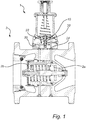
- Fig. 1 illustrates in cross section a pilot valve 1 and a piloted valve 3, also referred to as a main valve 3.
- the pilot valve 1 is typically a smaller valve 1 compared to the piloted valve 3, and is used to control a limited-flow control feed to the piloted valve 3.
- the pilot valve 1 is advantageous to use because a small and easily operated feed from the pilot valve 1 may be used to control a much higher pressure or higher flow feed of the piloted valve 3, which would otherwise require a much larger force to operate.
- the pilot valve 1 in Fig. 1 comprises a chamber 10, a first fluid inlet 20 arranged to be fluidly fed from an internal fluid flow of the piloted valve 3, and a second fluid inlet 22 arranged to be fluidly fed from an external fluid flow (not shown), wherein both the first and the second fluid inlets 20, 22 are arranged to provide fluid to the chamber 10.
- the pilot valve 1 further comprises a fluid outlet 24 for receiving fluid from the chamber 10 and for providing a fluid control feed to the piloted valve 3.
- a valve rod 30 arranged at least partly inside the chamber 10 is arranged to control fluid flow from the first and second fluid inlets 20, 22 to the fluid outlet 24.
- the piloted valve 3, or the main valve 3 may be any type of valve arranged to be connected to a pilot valve.
- the piloted valve is a two-plug valve having two separated force contacting surfaces 2a, 2b which the fluid control feed from the pilot valve 1 may act on.
- the piloted valve 3 may be a normally open valve. According to one example, the piloted valve 3 may be a normally closed valve.
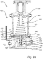
- Fig. 2a illustrates a pilot valve 101 in cross section, similar to the pilot valve 1 shown in Fig. 1 , but in greater detail.
- the pilot valve 101 in Fig. 2a comprises a first pilot valve body 102 having a chamber 110, a first fluid inlet 120 and a second fluid inlet 122 for providing fluid to the chamber 110 via a first internal fluid conduit 121 and a second internal fluid conduit 123.
- the first pilot valve body 102 further comprises a pilot valve fluid outlet 124 for receiving fluid from the chamber 110 via an internal pilot valve fluid outlet conduit 125, and providing a control feed to a piloted valve (as shown in Fig. 1 ).
- a valve rod 130 is arranged at least partly inside the chamber 110 for controlling fluid flow from the first and second fluid inlets 120, 122 to the fluid outlet 124 of the pilot valve, via the chamber 110.
- the pilot valve 101 in Fig. 2a further comprises a separating element 140 being connected to, and movable with the valve rod 130.
- the separating element 140 comprises a disc 141 having a first fluid contacting area 142, and a membrane 143 having a second fluid contacting area 144.
- the first fluid contacting area 142 of the separating element 140 is arranged at least partly opposite to the second fluid contacting area 144.
- the separating element 140 may comprise a piston instead of the membrane 140.
- the separating element 140 in Fig. 2a comprises two parts 141, 143, the separating element 140 may comprise only one part.
- the pilot valve 101 further comprises a pilot spring 160 housed in a pilot spring housing 162 defining a pilot spring chamber 163, the pilot spring 160 being arranged inside the pilot spring chamber 163, between a wall portion 164 in the pilot spring housing 162 and the first fluid contacting area 142.
- the wall portion 164 is facing the first fluid contacting area 142.
- a valve housing 150 comprises the valve body 102, the valve rod 130, the separating element 140, the pilot spring 160 and the pilot spring housing 162.
- a valve rod fluid conduit 132 is arranged inside the valve rod 130 and extends from the chamber 110, via a valve rod fluid conduit inlet 132a in the valve rod 130, through the valve rod 130 and through the separating element 140, whereby fluid from the first fluid inlet 120 is enabled to be in fluid communication with fluid in the pilot spring chamber 163.
- the first fluid inlet 120 is enabled to be in fluid communication with the first fluid contacting area 142 within the pilot spring housing 162.
- the separating element 140 fluidly separates fluid from the second fluid inlet 122, which fluid exerts a pressure on the second fluid contacting area 144, from fluid from the first fluid inlet 120, which fluid exerts a pressure on the first fluid contacting area 142.
- fluid from the second fluid inlet 122 is fluidly separated from fluid in the pilot spring chamber 163 by the separating element 140.
- the chamber 110 and the valve rod 130 have preferably circular cross sections.
- sealing elements such as o-rings may be used to seal different chamber portions from each other.
- other shapes and other cross sections of the chamber 110 and the valve rod 130 are possible to use.
- fluid from the first fluid inlet 120 is enabled to be in fluid communication with the first fluid contacting area 142 of the separating element 140, the fluid may exert a pressure on the first fluid contacting area 142 in order for a first force to be applied to the separating element 140.
- Fluid from the second fluid inlet 122 is enabled to be in fluid communication with the second fluid contacting area 144 of the separating element 140 and may thereby exert a pressure on the second fluid contacting area 144 to apply a second force to the separating element 140. Since the first fluid contacting area 142 is arranged on an opposite side to the second fluid contacting area 144, the first and the second force act on the separating element 140 in opposite directions.
- the first force acts on the separating element 140 in a direction from the first fluid contacting area 142 at least partly towards the second fluid contacting area 144
- the second force acts on the separating element in a direction from the second fluid contacting area 144 at least partly towards the first fluid contacting area 142.
- the pilot spring 160 arranged in the pilot spring housing 162 between the wall portion 164 and the first fluid contacting area 142, acts on the separating element 140 with a pilot spring force in at least partly the same direction as the first force.
- a combined force comprising the first force and the pilot spring force act on the separating element 140 in one direction
- the second force act on the separating element 140 in at least partly, an opposite direction.
- a difference between the combined force and the second force will normally cause a movement and/or a change in the movement of the separating element 140 and the valve rod 130, as the separating element 140 is arranged to move together with the valve rod 130.
- valve rod 130 In a first position of the valve rod 130, fluid from the first fluid inlet 120 is enabled to be in fluid communication with the pilot valve fluid outlet 124, and in a second position of the valve rod 130, fluid from the second fluid inlet 122 is enabled to be in fluid communication with the pilot valve fluid outlet 124. It should be understood that the valve rod 130 may be slightly moved within each of the first and second positions, as the first and the second positions are defined by which fluid inlet 120, 122 that is in fluid communication with the pilot valve fluid outlet 124. There is also an intermediate position of the valve rod 130, between its first and second positions where none of the fluid inlets 120, 122 are in fluid communication with the pilot valve fluid outlet 124. The different positions of the valve rod 130 will be described in greater detail with reference to Figs. 3-7 .
- Fig. 2b illustrates a pilot valve arrangement 301 comprising a first pilot valve part 101, described as the pilot valve 101 in Fig. 2a , and a second pilot valve part 201 arranged between the first pilot valve part 101 and a piloted valve (the piloted valve 3 shown only in Fig. 1 ).
- the fluid outlet 124 from the first pilot valve part 101 hereafter referred to as the first pilot valve fluid outlet 124, is fed to the second pilot valve part 201 instead of directly to a piloted valve as shown in Fig.1 .
- a fluid outlet 224 of the second pilot valve part 201 is fed to the piloted valve.
- the first pilot valve part 101 and the second pilot valve part 201 as described with reference to Figs. 2a-2b will now be described in further detail with reference to Figs. 3-7 .
- the pilot valve 101, or the first pilot valve part 101 will be described
- second, the second pilot valve part 201 will be described
- third, the structure and function of the pilot valve arrangement 301 comprising the first pilot valve part 101 and the second pilot valve part 201 will be described.
- the first valve first valve part 101 in Figs. 2a-2b is the same as the first valve part 101 in Figs. 3-7
- the second valve part 201 in Fig. 2b is the same as the second valve part 201 in Fig.
- FIG. 3-7 disclose different states and valve rod positions of the first and second valve parts 101, 102 of Figs. 2a-2b . Therefore, in order to facilitate the reading comprehension, some reference numerals are only indicated in the Figure where first described.
- the first pilot valve part 101 in Figs. 3-7 comprises a first sealing element 112 in the form of an o-ring 112, and a second sealing element 114 in the form of an o-ring 114.
- the first sealing element 112 is arranged within the chamber 110 and a first geometrical chamber cross section 112a tangents the first sealing element 112.
- the second sealing element 114 is arranged within the chamber 110 and a second geometrical chamber cross section 114a tangents the second sealing element 114.
- the chamber 110 comprises a first chamber portion 110a, a second chamber portion 110b and a third chamber portion 110c arranged between the first and second chamber portions 110a, 110b.
- the third chamber portion 110c comprises both the first and the second sealing elements 112, 114 and is at least partly defined by the portion 110c of the chamber 110 extending between first geometrical chamber cross section 112a and the second geometrical chamber cross section 114a.
- the first chamber portion 110a is at least partly defined by the portion 110a of the chamber 110 extending between the third chamber portion 110c and the first fluid inlet 120, or an inlet of the first internal fluid inlet conduit 121 to the chamber 110.
- the second chamber portion 110b is at least partly defined by the portion 110b of the chamber 110 extending between the third chamber portion 110c and the second fluid inlet 122 or an inlet of the second internal fluid inlet conduit 123 to the chamber 110.
- the first chamber portion 110a is arranged to receive fluid from the first fluid inlet 120, and the second chamber portion 110b is arranged to receive fluid from the second fluid inlet 122, while the third chamber 110c portion is arranged to provide fluid to the first pilot valve fluid outlet 124.
- the valve rod 130 comprises at least a first valve rod portion 130a, a second valve rod portion 130b, and a third valve rod portion 130c arranged between the first and second valve rod portions 130a, 130b.
- a diameter of each of the first and second valve rod portions 130a, 130b has a diameter larger than a diameter of the third valve rod portion 130c.
- the first and second valve rod portions 130a, 130b have the same diameter.
- the first and second valve rod portions 130a, 130b have different diameters.
- the third valve rod portion 130c may have a waist shape, or hour-glass shape, as shown in Figs. 3-7 , while the first and the second valve rod portions 130a, 130b may have a circular cross section with a constant diameter,
- the valve rod 130 in Figs. 3-7 further comprises a fourth valve rod portion 130d and a fifth valve rod portion 130e arranged between the first and the fourth valve rod portions 130a, 130d, A diameter of each of the first and fourth valve rod portions 130a, 130d has a diameter larger than a diameter of the fifth valve rod portion 130e.
- the fifth valve rod portion 130e may, similar to the third valve rod portion 130c, have a waist shape, or hour-glass shape, while the fourth valve rod portion 130d may have a circular cross section with a constant diameter.
- valve rod 130 The different positions of the valve rod 130 will now be described in further detail with reference to Figs. 3-7 .
- a static pressure of fluid in the first fluid inlet 120 is smaller than a static pressure of the fluid in the second fluid inlet 122.
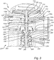
- the valve rod 130 When the combined force acting on the separating element 140 (indicated in Fig. 2a ) in a direction from the first fluid contacting area 142 at least partly towards the second fluid contacting area 143 by fluid in fluid communication with the first fluid inlet 120, and the pilot spring force of the spring, is larger than the second force acting on the separating element 140 in an at least partly opposite direction, the valve rod 130 will be in its first position as shown in Fig. 3 .
- the first fluid inlet 120, the first chamber portion 110a and the first pilot valve fluid outlet 124 are in fluid communication with each other, while the second fluid inlet 122 is restricted from being in fluid communication with the first pilot valve fluid outlet 124 by the valve rod 130 fluidly sealing against the second sealing element 114.
- the second chamber portion 110b is fluidly sealed from the third chamber portion 110c by a sealing contact between the valve rod 130 and the second sealing element 114
- the third valve rod portion 130c is arranged to be at least partly located in the first chamber portion 110a such that the first fluid inlet 120 is in fluid communication with the first pilot valve fluid outlet 124 via the first and third chamber portions 110a, 110c
- the second valve rod portion 130b is arranged to be at least partly located in both the second chamber 110b portion and the third chamber portion 110c such that the second fluid inlet 122 is restricted from being in fluid communication with the first pilot valve fluid outlet 124.
- the second force applied to the separating element 140 may overcome the combined force of the first force and the pilot spring force, and the separating element 140 will be moved further into the pilot spring chamber 163 (indicated in Fig. 2a ).
- the valve rod 130 will be moved from its first position to its second position, the second position of the valve rod 130 is shown in Figs. 5-7 .
- the second fluid inlet 122, the second chamber portion 110b and the first pilot valve fluid outlet 124 are in fluid communication with each other, while the first fluid inlet 120 is restricted from being in fluid communication with the first pilot valve fluid outlet 124 by the valve rod 130 fluidly sealing against the first sealing element 112.
- the first chamber portion 110a is fluidly sealed from the third chamber 110c portion by a sealing contact between the valve rod 130 and the first sealing element 112
- the third valve rod portion 130c is arranged to be at least partly located in the second chamber portion 110b such that the second fluid inlet 122 is in fluid communication with the first pilot valve fluid outlet 124 via the second and third chamber portions 110b, 110c
- the first valve rod portion 130a is arranged to be at least partly located in both the first chamber portion 110a and the third chamber portion 110c such that the first fluid inlet 120 is restricted from being in fluid communication with the first pilot valve fluid outlet 124.
- Fig. 4 an intermediate position of the valve rod 130 being in between its first and second position is illustrated.
- neither the first fluid inlet 120, nor the second fluid inlet 122 is in fluid communication with the first pilot valve fluid outlet 124, as fluid flow from both inlets 120, 122 are restricted by the valve rod 130, and the first and the second sealing elements 112, 114.
- the intermediate position of the valve rod 130 may occur after the valve rod 130 has been in its first position, and hence fluid in the first pilot valve fluid outlet 124 stem from fluid from the first fluid inlet 120, although the first fluid inlet 120 is not in fluid communication with the first pilot valve fluid outlet 124.
- the intermediate position of the valve rod 130 may also occur after the valve rod 130 has been in its second position, and hence fluid in the first pilot valve fluid outlet 124 stem from fluid from the second fluid inlet 122, although the second fluid inlet 122 is not in fluid communication with the first pilot valve fluid outlet 124.
- the second pilot valve part 201 in Fig. 2b is the same as the second pilot valve part in Figs. 3-7 , and the structure of the second pilot valve part 201 will now be described with reference to figs 3-7 .
- the second pilot valve part 201 in Figs. 3-7 comprises a second pilot valve body 202 having a compartment 210, a low pressure fluid inlet 220 for receiving fluid from the first pilot valve part 101 via the first pilot valve fluid outlet 124, and providing fluid to the compartment 210.
- the second pilot body 202 further comprises a high pressure fluid inlet 222 for providing fluid to the compartment 210, and a fluid outlet 224 for receiving fluid from the compartment 210 and providing fluid to a piloted valve (as shown in Fig. 1 ).
- the compartment 210 is defined at least partly by a first end wall section 264, a second end wall section 266 arranged opposite to and facing the first end wall section 264, and a lateral wall section 268 arranged between the first and second end wall sections 264, 266.
- a valve stem 230 is at least partly located inside the compartment 210.
- the valve stem 230 is connected to the valve rod 130 of the first pilot valve part 101 and moves together with the valve rod 130 in order to control fluid flow from the low pressure fluid inlet 220 to the fluid outlet 224 via the compartment 210, and configured to control fluid flow from the high pressure fluid inlet 222 to the fluid outlet 224 via the compartment 210.
- the second pilot valve part 201 further comprises a movable control body 250 comprised in, and movable within, the compartment 210.
- the movable control body 250 comprises a primary contacting area 252, a secondary contacting area 254 arranged opposite to the primary contacting area 252, and a cavity 256 for receiving fluid from the high pressure fluid inlet 222.
- the cavity 256 is arranged within the movable control body 250 between the primary and secondary contacting areas 252, 254.
- the movable control body 250 further comprises a through hole 258 extending from the primary contacting surface 252 to the secondary contacting area 254.
- the through hole 258 is for receiving the valve stem 230 and the valve stem 230 is thus movable within the movable control body 250.
- the valve stem 230 may extend through the through hole 258.
- the compartment 210 also houses a first spring 260 and a second spring 262, indicated in Fig. 3 .
- the first spring 260 is arranged between the primary contacting area 252 of the movable control body 250 and the first end wall section 264 of the compartment 210.
- the first spring 260 may exert a first spring force on the movable control body 250 via the primary contacting area 252.
- the first spring 260 is attached to the movable control body 250.
- the second spring 262 is arranged between a head 232 of the valve stem 230 and the primary contacting area 252 of the movable control body 250. Hereby the second spring 262 may exert a second spring force on the movable control body 250 via the primary contacting area 252.
- valve stem 230 is connected to the valve rod 130 by a combined part 330, which extends through the second pilot valve body 202 to the first pilot valve body 102 in a combining through hole 340.
- the head 232 of the valve stem 230 has a cross section which is larger than the combining through hole 340 for restricting the movement of the valve stem 230 into the combining through hole 340.
- the second pilot valve part 201 comprises a first sealing member 212 in the form of an o-ring 212, and a second sealing member 214 also in the form of an o-ring 214.
- the first sealing member 212 is arranged within the compartment 210 and a first geometrical compartment cross section 212a of the compartment 210 tangents the first sealing member 212.
- the second sealing member 214 is arranged within the compartment 210 and a second geometrical compartment cross section 214a of the compartment 210 tangents the second sealing member 214.
- the compartment 210 comprises a first compartment portion 210a defined at least partly by the primary contacting area 252 of the movable control body 250, the first end wall section 264 (indicated in Fig. 3 ) of the compartment 210 and the low pressure fluid inlet 220, a second compartment portion 210b defined at least partly by the second end wall section 266 and a portion of the lateral wall section 268 extending between the second end wall section 266 and a third compartment portion 210c.
- the third compartment portion 210c comprising the first and the second sealing members 212, 214 and being at least partly defined by the first geometrical compartment cross section 212a and the second geometrical compartment cross sections 212a, 214a and the fluid outlet 224.
- the first compartment portion 210a is arranged to receive fluid from the low pressure fluid inlet 220, and the second compartment portion 210b is arranged to be in fluid communication with the first compartment portion 210a via a valve stem conduit 240 within the valve stem 230 extending through the movable control body 250.
- the third compartment portion 210c is arranged to be in fluid communication with the fluid outlet 224.
- fluid in the first compartment portion 210a may exert a pressure on the primary contacting area 252 for applying a force to the movable control body 250
- fluid in the third compartment portion 210c may exert a pressure on the secondary contacting area 254 for applying a force to the movable control body 250.
- the movable control body 250 is arranged inside the compartment 210, within a fourth compartment potion 210d, such that the primary contacting area 252 faces the first compartment portion 210a and the secondary contacting area 254 faces the third compartment portion 210c.
- the valve stem 230 in Figs. 3-7 comprises at least a first valve stem portion 230a, a second valve stem portion 230b, and a third valve stem portion 230c arranged between the first and second valve stem portions 230a, 230b, as indicated in Fig. 4 .
- Each of the first and second valve stem portions 230a, 230b has a diameter larger than a diameter of the third valve stem portion 230c.
- the third valve stem portion 230c may have a waist shape, or hour-glass shape, as shown in Figs. 3-7 , while the first and the second valve stem portions 230a, 230b may have a circular cross section with a constant diameter,
- pilot valve arrangement 301 and second pilot valve part 201 in combination with the first pilot valve part 101 will now be described in more detail with reference to Figs. 3-7 .
- first pilot valve part 101 The functioning of the first pilot valve part 101 is explained above with reference to Figs. 2a , and Figs. 3-7 . Since the valve rod 130 of the first pilot valve part 101 is connected to the valve stem 230 of the second pilot valve part 201, the fluid flow inside the second pilot valve part 201 is at least partly determined by the position of the valve rod 130, and the pressure difference between the first and second fluid inlets 120, 122.
- the second pilot valve part 201 is in its first state, and provides for a first fluid flow path 290, shown in Fig. 4 , within the compartment and the second compartment portion 210a, to enable the low pressure fluid inlet 220 to be in fluid communication with the fluid outlet 224.
- the low pressure fluid inlet 220 is in fluid communication with the fluid outlet 224 via the first compartment portion 210a, the valve stem fluid conduit 240 within the valve stem 230, the second compartment portion 210b, the first fluid flow path 290 and the third compartment portion 210c.
- the first valve stem portion 230a in the first state, is arranged to fluidly seal against the inner wall defining the through hole 258 (indicated in Fig. 3 ) in the movable control body 250 in order for fluid in the cavity 256 in the movable control body 250 to be restricted from being in fluid communication with the third compartment portion 210c.
- the third valve stem portion 230c is arranged to be at least partly located in the third and second compartment portions 210b, 210c in order for fluid in the second compartment portion 210b to be in fluid communication with the third compartment portion 210c via the first fluid flow path 290.
- the first fluid path 290 being at least partly defined by at least a part of the lateral wall section 268 of the compartment 210 and/or the first sealing element 212 and at least a part of the third valve stem portion 230c.
- valve stem 230 in the first state, is arranged to fluidly seal against the inner wall defining the through hole 258 (indicated in Fig. 3 ) in the movable control body 250 by the second sealing member 214, such that the high pressure fluid inlet 220 is restricted from being in fluid communication with the fluid outlet 224.
- valve stem 230 is as close to the first pilot valve part 101 as possible and the head 232 of the valve stem 230 is in contact with the end wall section 264.
- the valve stem 230 provides for a second fluid flow path 292, indicated in Fig. 6 , within the compartment 210 to enable the high pressure fluid inlet 222 to be in fluid communication with the fluid outlet 224.
- the high pressure fluid inlet 222 is in fluid communication with the fluid outlet 224 via the cavity 256 of the movable control part 250, the second fluid flow path 292, and the third compartment portion 210c.
- the second valve stem portion 230b is arranged to fluidly seal against the lateral wall section 268 of the compartment 210 by the first sealing member 212 in order for fluid in the second compartment portion 210b to be restricted from being in fluid communication with the third compartment portion 210c.
- the first fluid flow path 290 is closed.
- the third valve stem portion 230c is arranged to be at least partly located in the cavity 256 and the third compartment portion 210c in order for fluid in the cavity 256 of the movable control body 250 to be in fluid communication with the third compartment portion 210c via the second fluid flow path 292.
- the second fluid path 292 being at least partly defined by at least a part of the inner wall defining the through hole 258 (indicated in Fig. 3 ) in the movable control body 250 and/or the second sealing member 214, and at least a part of the third valve stem portion 230c.
- valve stem 230 in the second state, is arranged to fluidly seal against the lateral wall section 268 of the compartment 210 by the first sealing member 212, such that the low pressure fluid inlet 220 is restricted from being in fluid communication with the fluid outlet 224.
- the fluid path 290 is closed as the second valve stem portion 230b fluidly seals the second compartment portion 210b from the third compartment portion by sealing against the first sealing member 212.
- the movable control body 250 is allowed to be moved from a primary position, as shown in Figs. 3-6 where the movable control body 250 still allows for a movement further towards the first end wall section 264, to a secondary position, as shown in Fig. 7 where the movable control body 250 has been moved as far as possible towards the first end wall section 264.
- a shoulder part 250a of the movable control body 250 rests against a recess 268a in the later wall section 268 of the compartment 210.
- the valve rod 130 and the valve stem 230 is in the same position as in Fig. 6 , however the movable control body 250 has moved from its primary position, as shown in Figs. 3-6 , to its secondary position.
- the movement between the primary position and the secondary position is due to that a first force applied to the primary contacting area 252 by the first and second springs 260, 262 and fluid in the first compartment portion 210a is smaller than a second force applied to the secondary contacting area 254 by fluid in the third compartment portion 210c.
- This state is referred to as the second pilot valve part 201 being in its third state.
- valve stem 230 is arranged to fluidly seal against the inner wall defining the through hole 258 in the movable control body 250 such that the high pressure fluid inlet 222 is restricted from being in fluid communication with the fluid outlet 224, and the valve stem 230 is arranged to fluidly seal against the lateral wall section 268 of the compartment 210 such that the low pressure fluid inlet 220 is restricted from being in fluid communication with the fluid outlet 224.
- both the first and second fluid contact paths, 290, 292 are closed.
- the first valve stem portion 230a is arranged to fluidly seal against the inner wall defining the through hole 258 in the movable control body 250 by the second sealing member 214 in order for fluid in the cavity 256 to be restricted from being in fluid communication with the third compartment portion 210c.
- the second valve stem portion 230b is arranged to fluidly seal against the lateral wall section 268 of the compartment 210 by the first sealing member 212, in order for fluid in the second compartment portion 210b to be restricted from being in fluid communication with the third compartment portion 210c.
- none of the low pressure or high pressure fluid inlets 220, 222 are in fluid communication with the fluid outlet 224, i.e. the first and second fluid flow paths 290, 292 (indicated in Figs. 4 and 6 ) are closed.
- further sealing members 116 indicated in Fig. 7 are arranged within the second pilot valve body 202, e.g. for sealing fluid from the high pressure fluid inlet 222 and fluid the cavity 256 within the movable control body 250, from the first compartment portion 210a.
- the pilot valve arrangement 301 will now be described when used together with a piloted valve, similar to the manner of the pilot valve 1 and the piloted valve 3 as shown in Fig. 1 .
- the static pressure of fluid in the first fluid inlet 120 is smaller than the static pressure of fluid in the second fluid inlet 122
- the static pressure of fluid in the second fluid inlet 122 is smaller than the static pressure of fluid in the high pressure fluid inlet 222.
- the piloted valve 3 is a normally open valve, receiving fluid with a static pressure of e.g. that of the second fluid inlet 122, and delivering fluid with a static pressure of e.g. that of the first fluid inlet 120.
- the pilot valve arrangement 301 or the first pilot valve part 101 may operate a normally closed piloted valve.
- the valve rod 130 When the pressure difference between the first fluid inlet 120 and the second fluid inlet 122 increases, e.g. by the static pressure in the second fluid inlet 122 increases and/or the static pressure of fluid in the first fluid inlet 120 decreases, the valve rod 130 will be moved from its first position to its second position. Hereby, fluid from the second fluid inlet 122 will be in fluid communication with the first pilot valve fluid outlet 124, and the low pressure fluid inlet 220 of the second pilot valve part 201. However, the second pilot valve part 201 is still in its first state and allows for a fluid communication between the low pressure fluid inlet 220 and the fluid outlet 224 , as illustrated in Fig. 5 .
- valve rod 130 When the valve rod 130 is in its second position, and the second pilot valve part 201 is its first state, fluid from the second fluid inlet 122 will be in fluid communication with the fluid outlet 224. Hence, the piloted valve (shown in Fig. 1 ) will receive a control feed in fluid communication with the second fluid inlet 122. Thus, the piloted valve will begin to close or be closed.
- the separating element 140 When the pressure difference between the first fluid inlet 120 and the second fluid inlet 122 further increases, e.g. by the static pressure in the second fluid inlet 122 further increases and/or the static pressure of fluid in the first fluid inlet 120 further decreases, the separating element 140 will be moved as far as possible within the pilot spring chamber 163. Still, fluid from the second fluid inlet 122 will be in fluid communication with the first pilot valve fluid outlet 124, and the low pressure fluid inlet 220 of the second pilot valve part 201. However, the second pilot valve part 201 will now be moved into its second state and allow for a fluid communication between the high pressure fluid inlet 222 and the fluid outlet 224, as illustrated in Fig. 6 .
- valve rod 130 When the valve rod 130 is in its second position, and the second pilot valve part 201 is its second state, fluid from the high pressure fluid inlet 222 will be in fluid communication with the fluid outlet 224.
- the piloted valve 3 (shown in Fig. 1 ) will receive a control feed in fluid communication with the high pressure fluid inlet 222.
- the piloted valve will either be closed in faster manner, or seal better when the piloted valve is fully closed, compared to the case when fluid from the second fluid inlet 122 is in fluid communication with the fluid outlet 224.
- the movable control body 250 is moved to its secondary position and none of the fluid inlets 220, 222 of the second pilot valve part 201 are allowed to be in fluid communication with the fluid outlet 224.
- the static pressure of fluid in the high pressure inlet is referred to as P0
- fluid from the second fluid inlet 122 in the first compartment portion 210a is referred to as P1
- the spring force of the first spring 260 is referred to Fs
- an inner and outer diameter of the first spring 260 in contact with the primary contacting area 252 are referred to as d and D, respectively
- the flow through the piloted valve (shown in Fig. 1 ) is denoted Q
- the valve constant of the piloted valve denoted Kv
- FIGs. 8-10 schematic illustrations of different fluid distribution systems for supplying fluid to a load are shown.
- the fluid distribution system 1000a comprises a load 1001a, a control unit 1002a, a supply line 1003a for supplying fluid to the load 1001 a, an intermediate line 1005a for transporting fluid from the load 1001 a to the control unit 1002a, a return line 1007a for transporting fluid from the control unit 1002a.
- a static pressure of fluid in the supply 1003a line is higher than a static pressure of fluid in the intermediate line 1005a
- the static pressure of fluid in the intermediate line 1005a is higher than a static pressure of fluid in the return line 1007a.
- the piloted valve 1009a or main valve 1009a is arranged on the supply line 1003a together with a pilot valve arrangement 1011 a as described above (indicated as 301 in e.g. Fig. 2b ) for piloting the main valve 1009a.
- the first fluid inlet (indicated as 120 in Figs. 2-7 ) to the pilot valve arrangement 1011 a is fluidly connected to the return line 1007a
- the high pressure inlet (indicated as 222 in Figs. 2-7 ) is fluidly connected to the supply line 1003a.
- the second fluid inlet (indicated as 122 in Figs.
- the pilot valve arrangement 1011 a facilitates in keeping a constant pressure drop over the control unit 1002a and in the sealing of the main valve 1009a by allowing for the high pressure from the supply line 1003a to be fed to the main valve.
- Dp represents the pressure drop over the load 1001 a
- Q represents the flow in the supply line 1003a over the piloted valve 1009a
- Kv is the valve constant of the piloted valve 1009a.
- the fluid distribution system 1000b comprises a load 1001 b, a control unit 1002b, a supply line 1003b for supplying fluid to the load 1001 b, an intermediate line 1005b for transporting fluid from the load 1001 b to the control unit 1002b, a return line 1007b for transporting fluid from the control unit 1002b.
- a static pressure of fluid in the supply 1003b line is higher than a static pressure of fluid in the intermediate line 1005b, and the static pressure of fluid in the intermediate line 1005b is higher than a static pressure of fluid in the return line 1007b.
- the piloted valve 1009b or main valve 1009b is arranged on the return line 1007b together with a pilot valve 1011 b, here no second pilot valve part (indicated as 201 in Figs. 2-7 ) is necessary and the pilot valve or the first pilot valve part (indicated as 1 in Fig. 1 and 101 in Figs. 2-7 ) is sufficient for controlling the main valve 1009b.
- the first fluid inlet (indicated as 120 in Figs. 2-7 ) to the pilot valve 1011 b is fluidly connected to the return line 1007b and the second fluid inlet (indicated as 122 in Figs. 2-7 ) is fluidly connected to the intermediate line 1005b.
- the pilot valve 1011 b facilitates in keeping the pressur drop over the control unit 1002b constant.
- the fluid distribution system 1000c comprises a load 1001c, a control unit 1002c, a supply line 1003c for supplying fluid to the load 1001 c via the control unit 1002c, a return line 1007c for transporting fluid away from said load 1001c, a by-pass line 1005c for transporting fluid between the supply line 1003c and the return line 1007c.
- a static pressure of fluid in the supply 1003b line is higher than a static pressure of fluid in the return line 1007b.
- a piloted valve 1009c or main valve 1009c is arranged on the by-pass line 1005c together with a pilot valve 1011c, here no second pilot valve part (indicated as 201 in Figs. 2-7 ) is necessary and the pilot valve or the first pilot valve part (indicated as 1 in Fig. 1 and 101 in Figs. 2-7 ) is sufficient for controlling the main valve 1009c.
- the first fluid inlet (indicated as 120 in Figs. 2-7 ) to the pilot valve 1011 c is fluidly connected to the return line 1007c via the intermediate line 1005c and the second fluid inlet (indicated as 122 in Figs. 2-7 ) is fluidly connected to the supply line 1003c via the intermediate line 1005c.
- the pilot valve facilitates in keeping a constant pressure drop over the main valve 1009c.
- the main valve 1009a, 1009b is normally open, and in Fig. 10 , the main valve 1009c is normally closed.
- control unit 1002a-c in each of Figs. 8-10 is a symbolic component representing any component or combination of components which provides for a controllable fluid flow, e.g. a control valve 1002a-c, a complete branch 1002a-c of e.g. lines, conduits, pipes and/or heat exchangers and/or another load 1002a-c.
- the pilot spring may be an adjustable pilot spring.
- the pilot valve and the piloted valve may be arranged in a fluid distribution system where the pressure drop over the control unit 1002a-c varies.
- a first pilot spring may be used in a fluid distribution system where the pressure drop over the control unit 1002a-c is between 10 kPa and 50 kPa
- a second pilot spring may be used in a fluid distribution system where the pressure drop over the control unit 1002a-c is between 30 kPa and 150 kPa
- a third pilot spring may be used in a fluid distribution system where the pressure drop over the control unit 1002a-c is between 80 kPa and 400 kPa.
- pilot valve While the pilot valve, the pilot valve arrangement, and the various fluid distribution systems are illustrated as having a particular configuration, one skilled on the art will recognize that such pilot valve, pilot valve arrangement and fluid distribution systems may include more or fewer components of different types. Indeed, one skilled in the art will recognize that the fluid distribution systems illustrated in Figs. 8-10 have been constructed to illustrate various aspects of the present inventive concept, and therefore is presented by way of illustration and not by way of limitation.
- the present inventive concept is not limited to the specific arrangement of external and internal fluid paths fed to the first and second fluid inlets, and the high pressure fluid inlet, as shown here, but the first fluid inlet may be fed from an internal flow of the piloted valve 1009a-c, and/or the second fluid inlet, and/or the high pressure fluid inlet may be fed from an external line somewhere else from the fluid distribution system.
- the external flow may e.g. derive from somewhere further upstream in the fluid distribution system.
Landscapes
- Engineering & Computer Science (AREA)
- Physics & Mathematics (AREA)
- General Engineering & Computer Science (AREA)
- Fluid Mechanics (AREA)
- General Physics & Mathematics (AREA)
- Automation & Control Theory (AREA)
- Mechanical Engineering (AREA)
- Power Engineering (AREA)
- Fluid-Driven Valves (AREA)
- Fluid-Pressure Circuits (AREA)
- Multiple-Way Valves (AREA)
- Mechanically-Actuated Valves (AREA)
Priority Applications (18)
| Application Number | Priority Date | Filing Date | Title |
|---|---|---|---|
| EP14159474.7A EP2918882B1 (en) | 2014-03-13 | 2014-03-13 | Pilot valve arrangement |
| ES14159474.7T ES2625346T3 (es) | 2014-03-13 | 2014-03-13 | Disposición de válvula piloto |
| DK14159474.7T DK2918882T3 (en) | 2014-03-13 | 2014-03-13 | Control valve assembly |
| PL14159474T PL2918882T3 (pl) | 2014-03-13 | 2014-03-13 | Układ zaworu pilotowego |
| PT141594747T PT2918882T (pt) | 2014-03-13 | 2014-03-13 | Disposição de válvula piloto |
| HUE14159474A HUE034324T2 (en) | 2014-03-13 | 2014-03-13 | Relief valve arrangement |
| RS20170432A RS55877B1 (sr) | 2014-03-13 | 2014-03-13 | Sklop pilot ventila |
| SI201430186T SI2918882T1 (sl) | 2014-03-13 | 2014-03-13 | Pilotna ventilna ureditev |
| CN201580012795.0A CN106104115B (zh) | 2014-03-13 | 2015-03-12 | 先导阀装置 |
| AU2015228868A AU2015228868B2 (en) | 2014-03-13 | 2015-03-12 | Pilot valve arrangement |
| SG11201607110YA SG11201607110YA (en) | 2014-03-13 | 2015-03-12 | Pilot valve arrangement |
| PCT/EP2015/055136 WO2015136025A1 (en) | 2014-03-13 | 2015-03-12 | Pilot valve arrangement |
| KR1020167027682A KR20160130298A (ko) | 2014-03-13 | 2015-03-12 | 파일럿 밸브 장치 |
| RU2016136635A RU2016136635A (ru) | 2014-03-13 | 2015-03-12 | Устройство управляющего клапана |
| US15/124,598 US9841119B2 (en) | 2014-03-13 | 2015-03-12 | Pilot valve arrangement |
| CA2941793A CA2941793A1 (en) | 2014-03-13 | 2015-03-12 | Pilot valve arrangement |
| JP2016556287A JP2017507304A (ja) | 2014-03-13 | 2015-03-12 | パイロット弁構成体 |
| HRP20170763TT HRP20170763T1 (hr) | 2014-03-13 | 2017-05-22 | Sklop pilot ventila |
Applications Claiming Priority (1)
| Application Number | Priority Date | Filing Date | Title |
|---|---|---|---|
| EP14159474.7A EP2918882B1 (en) | 2014-03-13 | 2014-03-13 | Pilot valve arrangement |
Publications (2)
| Publication Number | Publication Date |
|---|---|
| EP2918882A1 EP2918882A1 (en) | 2015-09-16 |
| EP2918882B1 true EP2918882B1 (en) | 2017-03-01 |
Family
ID=50241293
Family Applications (1)
| Application Number | Title | Priority Date | Filing Date |
|---|---|---|---|
| EP14159474.7A Active EP2918882B1 (en) | 2014-03-13 | 2014-03-13 | Pilot valve arrangement |
Country Status (18)
| Country | Link |
|---|---|
| US (1) | US9841119B2 (sr) |
| EP (1) | EP2918882B1 (sr) |
| JP (1) | JP2017507304A (sr) |
| KR (1) | KR20160130298A (sr) |
| CN (1) | CN106104115B (sr) |
| AU (1) | AU2015228868B2 (sr) |
| CA (1) | CA2941793A1 (sr) |
| DK (1) | DK2918882T3 (sr) |
| ES (1) | ES2625346T3 (sr) |
| HR (1) | HRP20170763T1 (sr) |
| HU (1) | HUE034324T2 (sr) |
| PL (1) | PL2918882T3 (sr) |
| PT (1) | PT2918882T (sr) |
| RS (1) | RS55877B1 (sr) |
| RU (1) | RU2016136635A (sr) |
| SG (1) | SG11201607110YA (sr) |
| SI (1) | SI2918882T1 (sr) |
| WO (1) | WO2015136025A1 (sr) |
Families Citing this family (6)
| Publication number | Priority date | Publication date | Assignee | Title |
|---|---|---|---|---|
| PT3449331T (pt) | 2016-04-26 | 2020-02-03 | Oxford Flow Ltd | Dispositivo para controlar o escoamento de um fluido |
| DE202017104079U1 (de) * | 2017-07-07 | 2017-08-21 | Samson Ag | Stellantrieb für Prozessventile |
| CN107576052A (zh) * | 2017-09-25 | 2018-01-12 | 江阴市南丰科技有限公司 | 一种用于化工生产的加热设备 |
| CN107606292B (zh) * | 2017-09-29 | 2019-03-12 | 中国长江电力股份有限公司 | 一种嵌套式双活塞先导阀 |
| CN110578728B (zh) * | 2019-10-11 | 2024-08-06 | 广东冠邦科技有限公司 | 自动换向阀 |
| BE1028145B1 (nl) | 2020-03-11 | 2021-10-12 | Atlas Copco Airpower Nv | Klep voor een vacuüminrichting en vacuüminrichting voorzien van zo een klep |
Family Cites Families (18)
| Publication number | Priority date | Publication date | Assignee | Title |
|---|---|---|---|---|
| US1841608A (en) * | 1925-12-07 | 1932-01-19 | I P Morris Corp | Check valve |
| US2914079A (en) * | 1954-04-06 | 1959-11-24 | Western States Machine Co | Quick acting control valve for water driven centrifugal machines |
| DE1199642B (de) * | 1958-10-18 | 1965-08-26 | Ad Struever G M B H | Einrichtung zum Regeln der unter Druck zugefuehrten Abgabefluessigkeitsmenge eines Betankungsfahrzeuges, insbesondere zum Betanken von Flugzeugen, auf einen konstanten Druck am Ende des an eine feste Rohrleitung des Fahrzeuges angeschlossenen Abgabe-schlauches |
| FR1240499A (fr) * | 1958-11-20 | 1960-09-02 | Fairchild Engine & Airplane | Régulateur de position commandé par la pression |
| US3286725A (en) * | 1961-02-02 | 1966-11-22 | Parker Hannifin Corp | Hydrant pressure regulator |
| US3362424A (en) * | 1965-05-05 | 1968-01-09 | Vapor Corp | Fluid pressure regulating system |
| US3481356A (en) * | 1966-05-24 | 1969-12-02 | Whittaker Corp | Redundant pressure regulating system |
| GB1371898A (en) * | 1970-11-20 | 1974-10-30 | Normalair Garrett Ltd | Control means for fluid flow valves |
| US3865128A (en) * | 1972-09-08 | 1975-02-11 | Vijay K Zadoo | Pressure regulating and shut-off valve |
| US3792713A (en) * | 1973-05-21 | 1974-02-19 | Vapor Corp | Pressure regulator with flow limiter |
| US3825026A (en) * | 1973-06-01 | 1974-07-23 | Vapor Corp | Inline valve |
| US3792716A (en) * | 1973-06-13 | 1974-02-19 | Vapor Corp | Inline valve with reverse pressure closing means |
| US4609008A (en) * | 1985-09-11 | 1986-09-02 | Anderson-Greenwood Usa, Inc. | Non-flowing pressure responsive pilot valve |
| US6209577B1 (en) * | 1998-05-12 | 2001-04-03 | Curtiss-Wright Flow Control Corporation | Modulating action non-flowing pilot operated relief valve |
| US20070157979A1 (en) * | 2006-01-06 | 2007-07-12 | Caterpillar Inc. | Fluid-control system |
| US20100282989A1 (en) * | 2007-07-11 | 2010-11-11 | Microflow International Pty Limited | Valve |
| US8627846B2 (en) * | 2009-11-06 | 2014-01-14 | Pentair Valves & Controls US LP | Pressure regulator having an integral pilot and self-relieving mechanism |
| CN102654149B (zh) * | 2012-05-18 | 2015-06-03 | 常德中联重科液压有限公司 | 液压控制阀 |
-
2014
- 2014-03-13 RS RS20170432A patent/RS55877B1/sr unknown
- 2014-03-13 HU HUE14159474A patent/HUE034324T2/en unknown
- 2014-03-13 EP EP14159474.7A patent/EP2918882B1/en active Active
- 2014-03-13 DK DK14159474.7T patent/DK2918882T3/en active
- 2014-03-13 PL PL14159474T patent/PL2918882T3/pl unknown
- 2014-03-13 ES ES14159474.7T patent/ES2625346T3/es active Active
- 2014-03-13 PT PT141594747T patent/PT2918882T/pt unknown
- 2014-03-13 SI SI201430186T patent/SI2918882T1/sl unknown
-
2015
- 2015-03-12 US US15/124,598 patent/US9841119B2/en active Active
- 2015-03-12 KR KR1020167027682A patent/KR20160130298A/ko not_active Withdrawn
- 2015-03-12 CA CA2941793A patent/CA2941793A1/en not_active Abandoned
- 2015-03-12 WO PCT/EP2015/055136 patent/WO2015136025A1/en not_active Ceased
- 2015-03-12 CN CN201580012795.0A patent/CN106104115B/zh active Active
- 2015-03-12 SG SG11201607110YA patent/SG11201607110YA/en unknown
- 2015-03-12 JP JP2016556287A patent/JP2017507304A/ja not_active Withdrawn
- 2015-03-12 RU RU2016136635A patent/RU2016136635A/ru not_active Application Discontinuation
- 2015-03-12 AU AU2015228868A patent/AU2015228868B2/en active Active
-
2017
- 2017-05-22 HR HRP20170763TT patent/HRP20170763T1/hr unknown
Non-Patent Citations (1)
| Title |
|---|
| None * |
Also Published As
| Publication number | Publication date |
|---|---|
| SG11201607110YA (en) | 2016-09-29 |
| CN106104115A (zh) | 2016-11-09 |
| EP2918882A1 (en) | 2015-09-16 |
| ES2625346T3 (es) | 2017-07-19 |
| PT2918882T (pt) | 2017-05-25 |
| CN106104115B (zh) | 2017-12-08 |
| HUE034324T2 (en) | 2018-02-28 |
| US20170016554A1 (en) | 2017-01-19 |
| JP2017507304A (ja) | 2017-03-16 |
| AU2015228868A1 (en) | 2016-09-01 |
| RU2016136635A (ru) | 2018-04-18 |
| DK2918882T3 (en) | 2017-06-06 |
| PL2918882T3 (pl) | 2017-08-31 |
| US9841119B2 (en) | 2017-12-12 |
| AU2015228868B2 (en) | 2019-08-29 |
| RS55877B1 (sr) | 2017-08-31 |
| SI2918882T1 (sl) | 2017-08-31 |
| HRP20170763T1 (hr) | 2017-08-11 |
| RU2016136635A3 (sr) | 2018-08-06 |
| KR20160130298A (ko) | 2016-11-10 |
| WO2015136025A1 (en) | 2015-09-17 |
| CA2941793A1 (en) | 2015-09-17 |
Similar Documents
| Publication | Publication Date | Title |
|---|---|---|
| AU2015228868B2 (en) | Pilot valve arrangement | |
| JP5049296B2 (ja) | ドームロード型圧力調整器 | |
| EP2918881B1 (en) | Pilot valve | |
| US7108006B2 (en) | Subsea actuator assemblies and methods for extending the water depth capabilities of subsea actuator assemblies | |
| US8474786B2 (en) | Valve stem and valve plug apparatus for use with fluid regulators | |
| CN102575782A (zh) | 微型机械装置和控制方法 | |
| US9298189B2 (en) | Automatic flow control system and apparatus | |
| AU2018344825B2 (en) | A valve for controlling fluid flow, a fluid distribution system and a method for measuring differential pressure | |
| US11248717B2 (en) | Modular smart solenoid valve | |
| US9909671B2 (en) | Low leak pilot operated spool valve | |
| CN105485375A (zh) | 三路直通气动阀 |
Legal Events
| Date | Code | Title | Description |
|---|---|---|---|
| PUAI | Public reference made under article 153(3) epc to a published international application that has entered the european phase |
Free format text: ORIGINAL CODE: 0009012 |
|
| AK | Designated contracting states |
Kind code of ref document: A1 Designated state(s): AL AT BE BG CH CY CZ DE DK EE ES FI FR GB GR HR HU IE IS IT LI LT LU LV MC MK MT NL NO PL PT RO RS SE SI SK SM TR |
|
| AX | Request for extension of the european patent |
Extension state: BA ME |
|
| 17P | Request for examination filed |
Effective date: 20160229 |
|
| RBV | Designated contracting states (corrected) |
Designated state(s): AL AT BE BG CH CY CZ DE DK EE ES FI FR GB GR HR HU IE IS IT LI LT LU LV MC MK MT NL NO PL PT RO RS SE SI SK SM TR |
|
| RIN1 | Information on inventor provided before grant (corrected) |
Inventor name: VOLOVEC, PETER Inventor name: LAZOV, SLAVE |
|
| 17Q | First examination report despatched |
Effective date: 20160704 |
|
| RIC1 | Information provided on ipc code assigned before grant |
Ipc: F16K 1/12 20060101ALI20160714BHEP Ipc: G05D 16/16 20060101ALI20160714BHEP Ipc: G05D 16/06 20060101ALI20160714BHEP Ipc: G05D 16/10 20060101ALI20160714BHEP Ipc: F16K 31/128 20060101AFI20160714BHEP |
|
| GRAP | Despatch of communication of intention to grant a patent |
Free format text: ORIGINAL CODE: EPIDOSNIGR1 |
|
| INTG | Intention to grant announced |
Effective date: 20160922 |
|
| GRAS | Grant fee paid |
Free format text: ORIGINAL CODE: EPIDOSNIGR3 |
|
| GRAA | (expected) grant |
Free format text: ORIGINAL CODE: 0009210 |
|
| AK | Designated contracting states |
Kind code of ref document: B1 Designated state(s): AL AT BE BG CH CY CZ DE DK EE ES FI FR GB GR HR HU IE IS IT LI LT LU LV MC MK MT NL NO PL PT RO RS SE SI SK SM TR |
|
| REG | Reference to a national code |
Ref country code: GB Ref legal event code: FG4D |
|
| REG | Reference to a national code |
Ref country code: CH Ref legal event code: EP Ref country code: AT Ref legal event code: REF Ref document number: 871783 Country of ref document: AT Kind code of ref document: T Effective date: 20170315 |
|
| REG | Reference to a national code |
Ref country code: IE Ref legal event code: FG4D |
|
| REG | Reference to a national code |
Ref country code: FR Ref legal event code: PLFP Year of fee payment: 4 |
|
| REG | Reference to a national code |
Ref country code: DE Ref legal event code: R096 Ref document number: 602014006993 Country of ref document: DE |
|
| REG | Reference to a national code |
Ref country code: NL Ref legal event code: FP |
|
| REG | Reference to a national code |
Ref country code: RO Ref legal event code: EPE |
|
| REG | Reference to a national code |
Ref country code: SE Ref legal event code: TRGR |
|
| REG | Reference to a national code |
Ref country code: HR Ref legal event code: TUEP Ref document number: P20170763 Country of ref document: HR |
|
| REG | Reference to a national code |
Ref country code: PT Ref legal event code: SC4A Ref document number: 2918882 Country of ref document: PT Date of ref document: 20170525 Kind code of ref document: T Free format text: AVAILABILITY OF NATIONAL TRANSLATION Effective date: 20170511 |
|
| REG | Reference to a national code |
Ref country code: DK Ref legal event code: T3 Effective date: 20170601 |
|
| REG | Reference to a national code |
Ref country code: LT Ref legal event code: MG4D Ref country code: NO Ref legal event code: T2 Effective date: 20170301 |
|
| REG | Reference to a national code |
Ref country code: ES Ref legal event code: FG2A Ref document number: 2625346 Country of ref document: ES Kind code of ref document: T3 Effective date: 20170719 |
|
| PG25 | Lapsed in a contracting state [announced via postgrant information from national office to epo] |
Ref country code: LT Free format text: LAPSE BECAUSE OF FAILURE TO SUBMIT A TRANSLATION OF THE DESCRIPTION OR TO PAY THE FEE WITHIN THE PRESCRIBED TIME-LIMIT Effective date: 20170301 Ref country code: GR Free format text: LAPSE BECAUSE OF FAILURE TO SUBMIT A TRANSLATION OF THE DESCRIPTION OR TO PAY THE FEE WITHIN THE PRESCRIBED TIME-LIMIT Effective date: 20170602 |
|
| REG | Reference to a national code |
Ref country code: HR Ref legal event code: T1PR Ref document number: P20170763 Country of ref document: HR |
|
| PG25 | Lapsed in a contracting state [announced via postgrant information from national office to epo] |
Ref country code: BG Free format text: LAPSE BECAUSE OF FAILURE TO SUBMIT A TRANSLATION OF THE DESCRIPTION OR TO PAY THE FEE WITHIN THE PRESCRIBED TIME-LIMIT Effective date: 20170601 |
|
| PG25 | Lapsed in a contracting state [announced via postgrant information from national office to epo] |
Ref country code: EE Free format text: LAPSE BECAUSE OF FAILURE TO SUBMIT A TRANSLATION OF THE DESCRIPTION OR TO PAY THE FEE WITHIN THE PRESCRIBED TIME-LIMIT Effective date: 20170301 |
|
| REG | Reference to a national code |
Ref country code: CH Ref legal event code: PL |
|
| REG | Reference to a national code |
Ref country code: SK Ref legal event code: T3 Ref document number: E 24452 Country of ref document: SK |
|
| PG25 | Lapsed in a contracting state [announced via postgrant information from national office to epo] |
Ref country code: SM Free format text: LAPSE BECAUSE OF FAILURE TO SUBMIT A TRANSLATION OF THE DESCRIPTION OR TO PAY THE FEE WITHIN THE PRESCRIBED TIME-LIMIT Effective date: 20170301 Ref country code: IS Free format text: LAPSE BECAUSE OF FAILURE TO SUBMIT A TRANSLATION OF THE DESCRIPTION OR TO PAY THE FEE WITHIN THE PRESCRIBED TIME-LIMIT Effective date: 20170701 |
|
| REG | Reference to a national code |
Ref country code: DE Ref legal event code: R097 Ref document number: 602014006993 Country of ref document: DE |
|
| REG | Reference to a national code |
Ref country code: IE Ref legal event code: MM4A |
|
| PLBE | No opposition filed within time limit |
Free format text: ORIGINAL CODE: 0009261 |
|
| STAA | Information on the status of an ep patent application or granted ep patent |
Free format text: STATUS: NO OPPOSITION FILED WITHIN TIME LIMIT |
|
| PG25 | Lapsed in a contracting state [announced via postgrant information from national office to epo] |
Ref country code: LU Free format text: LAPSE BECAUSE OF NON-PAYMENT OF DUE FEES Effective date: 20170313 Ref country code: MC Free format text: LAPSE BECAUSE OF FAILURE TO SUBMIT A TRANSLATION OF THE DESCRIPTION OR TO PAY THE FEE WITHIN THE PRESCRIBED TIME-LIMIT Effective date: 20170301 |
|
| 26N | No opposition filed |
Effective date: 20171204 |
|
| REG | Reference to a national code |
Ref country code: HR Ref legal event code: ODRP Ref document number: P20170763 Country of ref document: HR Payment date: 20180219 Year of fee payment: 5 |
|
| REG | Reference to a national code |
Ref country code: FR Ref legal event code: PLFP Year of fee payment: 5 |
|
| PG25 | Lapsed in a contracting state [announced via postgrant information from national office to epo] |
Ref country code: CH Free format text: LAPSE BECAUSE OF NON-PAYMENT OF DUE FEES Effective date: 20170331 Ref country code: LI Free format text: LAPSE BECAUSE OF NON-PAYMENT OF DUE FEES Effective date: 20170331 Ref country code: IE Free format text: LAPSE BECAUSE OF NON-PAYMENT OF DUE FEES Effective date: 20170313 |
|
| REG | Reference to a national code |
Ref country code: HU Ref legal event code: AG4A Ref document number: E034324 Country of ref document: HU |
|
| PGFP | Annual fee paid to national office [announced via postgrant information from national office to epo] |
Ref country code: CZ Payment date: 20180223 Year of fee payment: 5 Ref country code: FI Payment date: 20180216 Year of fee payment: 5 Ref country code: RO Payment date: 20180227 Year of fee payment: 5 Ref country code: NO Payment date: 20180221 Year of fee payment: 5 Ref country code: DK Payment date: 20180216 Year of fee payment: 5 |
|
| PGFP | Annual fee paid to national office [announced via postgrant information from national office to epo] |
Ref country code: LV Payment date: 20180321 Year of fee payment: 5 Ref country code: TR Payment date: 20180305 Year of fee payment: 5 Ref country code: PT Payment date: 20180209 Year of fee payment: 5 Ref country code: PL Payment date: 20180206 Year of fee payment: 5 Ref country code: HU Payment date: 20180214 Year of fee payment: 5 Ref country code: BE Payment date: 20180215 Year of fee payment: 5 Ref country code: HR Payment date: 20180219 Year of fee payment: 5 Ref country code: SK Payment date: 20180221 Year of fee payment: 5 Ref country code: SI Payment date: 20180219 Year of fee payment: 5 Ref country code: RS Payment date: 20180219 Year of fee payment: 5 |
|
| PGFP | Annual fee paid to national office [announced via postgrant information from national office to epo] |
Ref country code: ES Payment date: 20180403 Year of fee payment: 5 |
|
| PG25 | Lapsed in a contracting state [announced via postgrant information from national office to epo] |
Ref country code: MT Free format text: LAPSE BECAUSE OF NON-PAYMENT OF DUE FEES Effective date: 20170313 |
|
| GBPC | Gb: european patent ceased through non-payment of renewal fee |
Effective date: 20180313 |
|
| PG25 | Lapsed in a contracting state [announced via postgrant information from national office to epo] |
Ref country code: GB Free format text: LAPSE BECAUSE OF NON-PAYMENT OF DUE FEES Effective date: 20180313 |
|
| REG | Reference to a national code |
Ref country code: AT Ref legal event code: UEP Ref document number: 871783 Country of ref document: AT Kind code of ref document: T Effective date: 20170301 |
|
| REG | Reference to a national code |
Ref country code: HR Ref legal event code: PBON Ref document number: P20170763 Country of ref document: HR Effective date: 20190313 |
|
| REG | Reference to a national code |
Ref country code: DK Ref legal event code: EBP Effective date: 20190331 Ref country code: NO Ref legal event code: MMEP |
|
| PG25 | Lapsed in a contracting state [announced via postgrant information from national office to epo] |
Ref country code: CY Free format text: LAPSE BECAUSE OF FAILURE TO SUBMIT A TRANSLATION OF THE DESCRIPTION OR TO PAY THE FEE WITHIN THE PRESCRIBED TIME-LIMIT Effective date: 20170301 Ref country code: PT Free format text: LAPSE BECAUSE OF NON-PAYMENT OF DUE FEES Effective date: 20190913 Ref country code: CZ Free format text: LAPSE BECAUSE OF NON-PAYMENT OF DUE FEES Effective date: 20190313 Ref country code: FI Free format text: LAPSE BECAUSE OF NON-PAYMENT OF DUE FEES Effective date: 20190313 Ref country code: RO Free format text: LAPSE BECAUSE OF NON-PAYMENT OF DUE FEES Effective date: 20190313 |
|
| PG25 | Lapsed in a contracting state [announced via postgrant information from national office to epo] |
Ref country code: LV Free format text: LAPSE BECAUSE OF NON-PAYMENT OF DUE FEES Effective date: 20190313 Ref country code: RS Free format text: LAPSE BECAUSE OF NON-PAYMENT OF DUE FEES Effective date: 20190916 Ref country code: MK Free format text: LAPSE BECAUSE OF FAILURE TO SUBMIT A TRANSLATION OF THE DESCRIPTION OR TO PAY THE FEE WITHIN THE PRESCRIBED TIME-LIMIT Effective date: 20170301 |
|
| REG | Reference to a national code |
Ref country code: SK Ref legal event code: MM4A Ref document number: E 24452 Country of ref document: SK Effective date: 20190313 |
|
| REG | Reference to a national code |
Ref country code: BE Ref legal event code: MM Effective date: 20190331 |
|
| REG | Reference to a national code |
Ref country code: SI Ref legal event code: KO00 Effective date: 20191111 |
|
| PG25 | Lapsed in a contracting state [announced via postgrant information from national office to epo] |
Ref country code: NO Free format text: LAPSE BECAUSE OF NON-PAYMENT OF DUE FEES Effective date: 20190331 Ref country code: SK Free format text: LAPSE BECAUSE OF NON-PAYMENT OF DUE FEES Effective date: 20190313 Ref country code: HU Free format text: LAPSE BECAUSE OF NON-PAYMENT OF DUE FEES Effective date: 20190314 Ref country code: HR Free format text: LAPSE BECAUSE OF NON-PAYMENT OF DUE FEES Effective date: 20190313 |
|
| PG25 | Lapsed in a contracting state [announced via postgrant information from national office to epo] |
Ref country code: SI Free format text: LAPSE BECAUSE OF NON-PAYMENT OF DUE FEES Effective date: 20190314 Ref country code: BE Free format text: LAPSE BECAUSE OF NON-PAYMENT OF DUE FEES Effective date: 20190331 |
|
| PG25 | Lapsed in a contracting state [announced via postgrant information from national office to epo] |
Ref country code: DK Free format text: LAPSE BECAUSE OF NON-PAYMENT OF DUE FEES Effective date: 20190331 |
|
| REG | Reference to a national code |
Ref country code: ES Ref legal event code: FD2A Effective date: 20200724 |
|
| PG25 | Lapsed in a contracting state [announced via postgrant information from national office to epo] |
Ref country code: AL Free format text: LAPSE BECAUSE OF FAILURE TO SUBMIT A TRANSLATION OF THE DESCRIPTION OR TO PAY THE FEE WITHIN THE PRESCRIBED TIME-LIMIT Effective date: 20170301 |
|
| REG | Reference to a national code |
Ref country code: AT Ref legal event code: MM01 Ref document number: 871783 Country of ref document: AT Kind code of ref document: T Effective date: 20190313 |
|
| PG25 | Lapsed in a contracting state [announced via postgrant information from national office to epo] |
Ref country code: ES Free format text: LAPSE BECAUSE OF NON-PAYMENT OF DUE FEES Effective date: 20190314 |
|
| PG25 | Lapsed in a contracting state [announced via postgrant information from national office to epo] |
Ref country code: AT Free format text: LAPSE BECAUSE OF NON-PAYMENT OF DUE FEES Effective date: 20190313 Ref country code: PL Free format text: LAPSE BECAUSE OF NON-PAYMENT OF DUE FEES Effective date: 20190313 |
|
| PG25 | Lapsed in a contracting state [announced via postgrant information from national office to epo] |
Ref country code: TR Free format text: LAPSE BECAUSE OF NON-PAYMENT OF DUE FEES Effective date: 20190313 |
|
| P01 | Opt-out of the competence of the unified patent court (upc) registered |
Effective date: 20230530 |
|
| PGFP | Annual fee paid to national office [announced via postgrant information from national office to epo] |
Ref country code: NL Payment date: 20260123 Year of fee payment: 13 |
|
| PGFP | Annual fee paid to national office [announced via postgrant information from national office to epo] |
Ref country code: SE Payment date: 20260120 Year of fee payment: 13 |
|
| PGFP | Annual fee paid to national office [announced via postgrant information from national office to epo] |
Ref country code: DE Payment date: 20260216 Year of fee payment: 13 |
|
| PGFP | Annual fee paid to national office [announced via postgrant information from national office to epo] |
Ref country code: IT Payment date: 20260218 Year of fee payment: 13 |
|
| PGFP | Annual fee paid to national office [announced via postgrant information from national office to epo] |
Ref country code: FR Payment date: 20260120 Year of fee payment: 13 |