EP2921187B1 - Vorrichtung und verfahren zur flüssigkeitsverarbeitung - Google Patents
Vorrichtung und verfahren zur flüssigkeitsverarbeitung Download PDFInfo
- Publication number
- EP2921187B1 EP2921187B1 EP15163927.5A EP15163927A EP2921187B1 EP 2921187 B1 EP2921187 B1 EP 2921187B1 EP 15163927 A EP15163927 A EP 15163927A EP 2921187 B1 EP2921187 B1 EP 2921187B1
- Authority
- EP
- European Patent Office
- Prior art keywords
- inner bag
- bag
- fluid concentration
- fluid
- concentration device
- Prior art date
- Legal status (The legal status is an assumption and is not a legal conclusion. Google has not performed a legal analysis and makes no representation as to the accuracy of the status listed.)
- Active
Links
Images

Classifications
-
- A—HUMAN NECESSITIES
- A61—MEDICAL OR VETERINARY SCIENCE; HYGIENE
- A61M—DEVICES FOR INTRODUCING MEDIA INTO, OR ONTO, THE BODY; DEVICES FOR TRANSDUCING BODY MEDIA OR FOR TAKING MEDIA FROM THE BODY; DEVICES FOR PRODUCING OR ENDING SLEEP OR STUPOR
- A61M1/00—Suction or pumping devices for medical purposes; Devices for carrying-off, for treatment of, or for carrying-over, body-liquids; Drainage systems
- A61M1/02—Blood transfusion apparatus
- A61M1/0281—Apparatus for treatment of blood or blood constituents prior to transfusion, e.g. washing, filtering or thawing
-
- A—HUMAN NECESSITIES
- A61—MEDICAL OR VETERINARY SCIENCE; HYGIENE
- A61J—CONTAINERS SPECIALLY ADAPTED FOR MEDICAL OR PHARMACEUTICAL PURPOSES; DEVICES OR METHODS SPECIALLY ADAPTED FOR BRINGING PHARMACEUTICAL PRODUCTS INTO PARTICULAR PHYSICAL OR ADMINISTERING FORMS; DEVICES FOR ADMINISTERING FOOD OR MEDICINES ORALLY; BABY COMFORTERS; DEVICES FOR RECEIVING SPITTLE
- A61J1/00—Containers specially adapted for medical or pharmaceutical purposes
- A61J1/05—Containers specially adapted for medical or pharmaceutical purposes for collecting, storing or administering blood, plasma or medical fluids ; Infusion or perfusion containers
- A61J1/10—Bag-type containers
-
- A—HUMAN NECESSITIES
- A61—MEDICAL OR VETERINARY SCIENCE; HYGIENE
- A61J—CONTAINERS SPECIALLY ADAPTED FOR MEDICAL OR PHARMACEUTICAL PURPOSES; DEVICES OR METHODS SPECIALLY ADAPTED FOR BRINGING PHARMACEUTICAL PRODUCTS INTO PARTICULAR PHYSICAL OR ADMINISTERING FORMS; DEVICES FOR ADMINISTERING FOOD OR MEDICINES ORALLY; BABY COMFORTERS; DEVICES FOR RECEIVING SPITTLE
- A61J1/00—Containers specially adapted for medical or pharmaceutical purposes
- A61J1/14—Details; Accessories therefor
- A61J1/1462—Containers with provisions for hanging, e.g. integral adaptations of the container
-
- A—HUMAN NECESSITIES
- A61—MEDICAL OR VETERINARY SCIENCE; HYGIENE
- A61M—DEVICES FOR INTRODUCING MEDIA INTO, OR ONTO, THE BODY; DEVICES FOR TRANSDUCING BODY MEDIA OR FOR TAKING MEDIA FROM THE BODY; DEVICES FOR PRODUCING OR ENDING SLEEP OR STUPOR
- A61M1/00—Suction or pumping devices for medical purposes; Devices for carrying-off, for treatment of, or for carrying-over, body-liquids; Drainage systems
- A61M1/02—Blood transfusion apparatus
- A61M1/0209—Multiple bag systems for separating or storing blood components
Definitions
- the present invention relates to devices and methods of processing fluids. More particularly, the present invention relates to devices for concentrating fluids comprising discrete or particulate material dispersed in a liquid medium (eg blood) by removal of a proportion of the liquid medium (eg blood plasma), as well as methods of producing blood cell concentrates.
- a liquid medium eg blood
- a proportion of the liquid medium eg blood plasma
- a fluid concentration device for concentrating fluids comprising particulate material dispersed in a liquid medium by removal of a proportion of the liquid medium, the device comprising an outer bag formed of an impermeable material and an inner bag formed of a permeable material, and a port in the outer bag for introducing fluid into the cavity between the outer bag and the inner bag, wherein the permeable material allows the liquid medium, but not the particulate material, to pass into the inner bag, and wherein the inner bag contains a wadding material and is adapted for connection to a source of reduced pressure.
- the liquid medium removed from the fluid during the concentration process is difficult to recover from the absorbent material. This is undesirable where the liquid medium is valuable, such as in the case of blood plasma, which is removed from whole blood during the production of blood cell concentrates.
- the device of this invention is therefore advantageous primarily in that it provides a simple and inexpensive means of effectively concentrating fluids comprising discrete or particulate material dispersed in a liquid medium by removal of the liquid medium, which readily allows recovery of the liquid medium that is removed.
- the device of this invention may be used for any purpose where there is a need to concentrate a fluid comprising particulate or discrete material dispersed in a liquid medium.
- the device of this invention is of particular utility in the field of medicine to produce blood cell concentrates from whole blood by the removal of a proportion of the plasma component.
- the materials used to form the inner and outer bags are preferably flexible, to enable the bags to expand to accommodate fluid.
- Both the inner and outer bags are preferably formed from two sheets of material fastened together around their edges. This fastening process is preferably performed by heat welding to avoid introducing contaminants, such as adhesives, into the bag.
- the materials used to form the inner and outer bags are therefore preferably heat weldable.
- the outer bag may be formed of any suitable material, but preferred materials are tough and impermeable to reduce the risk of fluid contained within the device from leaking out or becoming contaminated.
- the outer bag is preferably formed of sheets of synthetic plastic, such as polyethylene, polyamide, polypropylene, polyurethane, polyester or polycarbonate.
- a particularly preferred material for the outer bag is polyvinylchloride (PVC) in sheet form.
- the thickness of the material of the outer bag can be varied depending on the desired properties.
- the thickness of the material of the outer bag is typically between 0.2mm and 3mm, more commonly between 0.5mm and 2mm, and preferably about 1 mm.
- the fluid is introduced into the device via the port in the outer bag. Fluid may also be discharged from the device through the same port, or through a second port. The presence of a second port enables fluid to be passed through the device continuously.
- the inner bag may be formed of any suitable material able to form a porous layer which allows liquid medium to pass through without the inner bag losing its integrity.
- the inner bag is preferably formed of sheets of synthetic plastic, such as polyethylene, polyamide, polypropylene, polyurethane, polyester or polyvinylchloride (PVC).
- PVC polyvinylchloride
- One particularly preferred material for the inner bag is porous polycarbonate membrane.
- the thickness of the material of the inner bag is typically between 0.1 mm and 2mm, more commonly between 0.2mm and 1mm, and preferably about 0.5mm.
- the porous material of the inner bag allows liquid medium to pass through, but substantially prevents the passage of the discrete or particulate material dispersed in the liquid medium. Where the discrete or particulate material is present in a range of sizes, the porous material may allow the particles at the lower end of the size range to pass through.
- the inner bag is preferably completely sealed so the liquid medium is only able to enter the inner bag by passing through its porous walls.
- the size of the pores in the porous material may be varied to suit the specific application of the device, but the diameter of the pores typically ranges from 0.01 ⁇ m to 1mm or more, more particularly 0.01 ⁇ m to 5 ⁇ m, and most particularly 0.1 ⁇ m to 2 ⁇ m.
- the pores of the inner bag should have a diameter of no greater than about 1 ⁇ m in order to retain substantially all the particulate matter of the blood in the cavity between the outer bag and the inner bag. It is preferred for the pores to be of a generally uniform size, but a range of pore sizes to be present.
- the fluid concentrating activity of the device requires the fluid entering the device to contact the inner bag, so the inner bag preferably presents the largest possible effective surface area on the interior of the device. This is achieved by suspending the inner bag within the outer bag by fastening the inner bag to the outer bag. This prevents the inner bag slumping or collapsing, which would reduce the effective surface area of the inner bag on the interior of the device.
- the inner bag is suspended within the outer bag at one or more fastening points that comprise a tab projecting from the edge of the inner bag sandwiched between the two layers of the outer bag in a region where the layers of the outer bag are welded together.
- the tab may be provided with one or more apertures to allow the two layers of the outer bag to weld together through the tab in order to anchor the tab in position. This is particularly preferable because the most preferred materials for forming the outer and inner bags, PVC and polycarbonate, do not weld strongly to one another.
- the inner bag preferably presents the largest possible effective surface area on the interior of the device.
- the inner bag is therefore preferably suspended within and fastened to the outer bag to prevent the inner bag from slumping or collapsing.
- the inner bag is preferably completely sealed, other than the means by which it is connected to the source of reduced pressure, so the liquid medium is only able to enter the inner bag by passing through its porous walls.
- the means by which the inner bag is coupled to the source of reduced pressure is preferably a drainage conduit by which liquid medium drawn from the fluid in the outer bag can be drained from the device.
- the drainage conduit may be formed of any suitable material, but is preferably formed of a flexible plastics material.
- the drainage conduit enters the device through a port in the outer bag and connects directly to the inner bag via a connector.
- the connector preferably forms a secure fastening between the drainage conduit and the inner bag to prevent leakage from the connection. This may be achieved by the connector having a flange portion, which provides a larger surface area for fastening to the inner bag.
- the drainage conduit preferably extends from the device and has a free end that can be attached to a vacuum pump or the like.
- a collection vessel may be interposed between the drainage conduit and the vacuum pump, to enable the collection of fluid drawn from the device.
- the inner bag preferably contains a wadding material to prevent it collapsing upon the application of a reduced pressure and ensure an even distribution of pressure throughout the inner bag.
- the wadding material is preferably a foam or non-woven fabric material, but may be any material that is sufficiently porous to allow fluid to pass through freely without clogging, and is sufficiently resilient to prevent the inner bag collapsing.
- fluid is introduced into the device through a port in the outer bag and enters the cavity between the outer and inner bags.
- Reduced pressure applied to the inner bag draws fluid through the permeable wall of the inner bag from the cavity, and carries it away from the device, resulting in the concentration of particles that are too large to pass through the porous wall of the inner bag in the cavity.
- the resulting concentrated fluid may be removed from the device through a port in the outer bag and the device disposed of or re-used.
- a fluid concentration device comprising an outer bag formed of an impermeable material, an inner bag formed of a permeable material and containing an absorbent material, wherein the inner bag is fastened to, and suspended within, the outer bag.
- This device is advantageous primarily in that it provides a self-contained, simple and inexpensive means of effectively concentrating fluids comprising discrete or particulate material dispersed in a liquid medium by removal of a proportion of the liquid medium.
- the material of the inner bag may allow the liquid medium, but not the discrete or particulate material, to pass into the inner bag and be held there by the absorbent material, thereby increasing the concentration of the discrete or particulate material outside the inner bag.
- This device is particularly effective as the inner bag is fastened to and suspended within the outer bag, which prevents the inner bag slumping or collapsing and so maintains a large effective surface area of the inner bag on the interior of the device.
- the preferred materials and structure of the outer and inner bags of this device are substantially the same as for the device of the first aspect of the invention.
- absorbent materials for use with this device are of the type commonly referred to as a "superabsorbers” or “superabsorbent materials”.
- Such materials are typically polymers that are capable of absorbing and retaining extremely large quantities of fluid relative to their own mass.
- such materials absorb aqueous solutions through hydrogen bonding with water molecules, and may absorb up to 200, 400, or 500 times or more their weight of water.
- polyacrylates ie salts of polyacrylic acid.
- the sodium salt of polyacrylic acid cross-linked sodium polyacrylate
- acrylic acid blended with sodium hydroxide in the presence of an initiator.
- superabsorbent polymers include polyacrylamide copolymer, ethylene maleic anhydride copolymer, cross-linked carboxymethylcellulose, polyvinylalcohol copolymers, cross-linked polyethylene oxide, starch-grafted copolymers of polyacrylonitrile, and others.
- alginate ie salts of alginic acid.
- alginate ie salts of alginic acid.
- Alginic acid is a linear copolymer with homopolymeric blocks of (1-4)-linked ⁇ -D-mannuronate and its C-5 epimer ⁇ -L-guluronate residues, covalently linked together in different sequences or blocks.
- Alginates that are particularly suitable are calcium alginate and sodium alginate.
- fluid comprising discrete or particulate material dispersed in a liquid medium passes through a port in the outer bag and enters the cavity between the outer and inner bag.
- the liquid medium may then pass through the permeable wall of the inner bag and be held there by the absorbent material, preventing it from passing back into the cavity between the outer and inner bags.
- particles that are too large to pass through the wall of the permeable inner bag are concentrated in the cavity.
- the resulting concentrated fluid may then be removed from the device, and the device disposed of.
- the liquid medium removed from the fluid during the concentration process is difficult to recover from the absorbent material. This is undesirable where the liquid medium is valuable, such as in the case of blood plasma, which is removed from whole blood during the production of blood cell concentrates.
- the device according to the first aspect of the invention is of particular utility in the field of medicine to produce blood cell concentrates from whole blood by the removal of a proportion of the plasma component, as it allows the blood plasma to be recovered easily.
- a method of processing blood which method comprises the steps of:
- the pressure differential applied across the permeable material draws at least blood plasma through the permeable material, while at least the blood cells remain in the outer bag.
- the method of this invention is advantageous primarily in that it provides a simple and inexpensive means of efficiently processing blood to produce blood cell concentrates and it allows the blood plasma removed from the blood to be recovered easily from the inner bag.
- the pressure differential across the permeable material may be generated by any suitable means, although it is preferably generated by applying a reduced pressure to the inner bag with the use of a pressure reducing means.
- the means employed to generate the reduced pressure preferably takes the form of a vacuum pump or the like.
- the pressure differential across the permeable material must be of sufficient magnitude to draw at least blood plasma through the permeable material, but is preferably not so great as to damage the blood cells or permeable material.
- the pressure differential is preferably applied continuously and may be applied in conjunction with agitation to facilitate the transmission of at least the plasma component of blood through the permeable material.
- the properties of the permeable material determine what components of the blood are removed by the method of the present invention.
- the method of this invention may employ a permeable material which only allows the transmission of the blood plasma, such that all particulate matter remains in the outer bag, in which case the pores of the permeable material may be up to 1 ⁇ m in diameter.
- the method of this invention may employ a permeable material that allows small particulate matter, such as thrombocytes (platelets), to pass through, such that only larger particulate matter, such as erythrocytes (red blood cells), remain in the outer bag.
- the pores of the permeable material may therefore be up to 3 ⁇ m in diameter, or up to 5 ⁇ m in diameter.
- the method of this invention may further comprise a step of processing the blood cell concentrate to remove a particular category of blood cells.
- leukocytes white blood cells
- erythrocytes red blood cells
- This may be carried out by passing the blood cell concentrate through a leukocyte reduction filter, which are well-known in the field.
- the method of this invention may also comprise a further step of collecting the plasma, and whatever other components of the blood that are drawn through the permeable material. This may be carried out by placing a receptacle between the inner bag and the pressure reducing means, such that whatever components of the blood are drawn through the permeable material are collected in the receptacle.
- Blood cell concentrates produced by the method of this invention are preferably suitable for administration to a patient and are therefore kept free from contamination with microorganisms.
- Whole blood may be introduced into the device through the port that connects the outer bag with the exterior of the device.
- the blood cell concentrate may be drained from the device via a separate outlet that connects the outer bag with the exterior of the device.
- blood may be passed through the device continuously such that the method of this invention is carried out as a continuous process.
- the method of this invention is preferably carried out as a batch process, in which the device is charged with blood via the inlet, with the outlet sealed, and the concentrated blood subsequently drained from the device by opening of the outlet.
- fluid may be introduced into and drained from the device through the same port, so a separate inlet and outlet are not necessarily.
- the proportion of plasma that is removed from an amount of blood by the method of this invention is dependent on the magnitude of the pressure differential across the permeable material, and the length of time that pressure differential is applied. Where the method of this invention is carried out as a continuous process, the proportion of plasma that is removed from an amount of blood is also dependent of the flow rate of the blood. In general, it is possible to produce more highly concentrated blood cell concentrates when the method of this invention is carried out as a batch process.
- a fluid concentration device which does not fall within the scope of the claimed invention, is generally designated 100.
- the device 100 is for concentrating fluids comprising discrete or particulate material dispersed in a liquid medium by removal of a proportion of the liquid medium.
- the device 100 comprises an outer bag 20 formed of a tough impermeable material, an inner bag 40 formed of a porous material and contained within the outer bag 20, and an absorbent material 44 encapsulated within the inner bag 40.
- the outer bag has an inlet port 22, through which fluid may pass into the device 100 and enter cavity 30 formed between the outer bag 20 and the inner bag 40, and an outlet port 24, though which fluid may exit the device 100.
- both an inlet port 22 and an outlet port 24 in the outer bag 20 enables fluid to flow though the device 100 continuously, allowing fluid concentration to be carried out as a continuous process. Fluid concentration may also be carried out in a batch process, in which the device 100 is charged with fluid via the inlet port 22, with the outlet port 24 sealed. The fluid held in the device 100 may then be concentrated and subsequently drained from the device 100 by opening the outlet port 24.
- other embodiments of the device 100 for concentrating fluid in a batch process may have only a single port through which fluid is both introduced into and drained from the device 100.
- the outer bag 20 is formed of polyvinylchloride (PVC) sheets and the inner bag 40 is formed of porous polycarbonate membrane. Both the outer bag 20 and inner bag 40 are formed by fastening two sheets of material together around their edges by heat welding.
- the material of the outer bag 20 is impermeable to the liquid medium of the fluid introduced into the device 100.
- the material of the inner bag 40 permits liquid medium, but not the discrete or particulate material, to pass through it and into the interior of the inner bag 40.
- the inner bag 40 is formed of material having pores with a maximum size of no greater than 5 ⁇ m to permit blood plasma, but not red blood cells, to pass through.
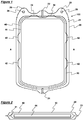
- the area around the edge of the outer bag 20 where the two polyvinylchloride (PVC) sheets are welded together defines a welded portion 21.
- This welded portion 21 projects from each upper corner of the outer bag 20 to form extensions 26.
- Each extension 26 has an aperture 28 to allow the device 100 to be hung from a suitable support.
- the area around the edge of the inner bag 40 where the two porous polycarbonate membranes are welded together also defines a welded portion 41.
- the absorbent material 44 is entirely encapsulated by the inner bag 40.
- the welded portion 41 around the edge of the inner bag 40 extends outwardly to form a number of tabs 42, which are fastened to the interior of the outer bag 20 at a number of points to suspend the inner bag 40 within the outer bag 20 (described in more detail below with reference to Figure 5 ).
- a fluid comprising discrete or particulate material dispersed in a liquid medium is introduced into the device 100 through the inlet port 22 in the outer bag 20 and enters the cavity 30 between the outer 20 and inner bag 40.
- the inlet 22 and outlet 24 ports are then sealed to prevent the fluid escaping the device during the concentration process.
- Fluid contained in cavity 30, passes through the porous walls of the inner bag 40 and is held there by the absorbent material 44, thereby increasing the concentration of the discrete or particulate material in the cavity 30.
- the device 100 may be gently agitated during the concentration process to facilitate passage of the liquid medium through the porous walls of the inner bag 40. Following concentration, the concentrated fluid contained in cavity 30 may be drained from the device via the outlet port 24, and the device disposed of.
- the device 200 comprises an outer bag 20 formed of a tough impermeable material, an inner bag 40 formed of a porous material and contained within the outer bag 20, and a wadding material 60 contained within the inner bag 40.
- Both the outer bag 20 and the inner bag 40 are formed by heat welding two sheets of material together in the welded portions 21,41 around their edges.
- the welded portion 21 at each upper corner of the outer bag 20 form extensions 26, each having an aperture 28 to allow the device 200 to be hung from a suitable support.
- the welded portion 41 of the inner bag 40 forms a number of tabs 42, which are fastened to the interior of the outer bag 20 at a number of points to suspend the inner bag 40 within the outer bag 20 (described in more detail below with reference to Figure 5 ).
- the device 200 has an inlet port 22, through which fluid may enter the device 200, and a drainage port 52, through which concentrated fluid may be drained from the device 200.
- Fluid concentration may also be carried out in a batch process, in which the device 100 is charged with fluid via the inlet port 22, with the outlet port 24 sealed. The fluid held in the device 100 may then be concentrated and subsequently drained from the device 100 by opening the outlet port 24.
- other embodiments of the device 100 for concentrating fluid in a batch process may have only a single port through which fluid is both introduced into and drained from the device 100.
- the device 200 also has a vacuum port 50, through which one end of a vacuum conduit 54 enters the device 200 and connects directly with the interior of the inner bag 40.
- the other end of the vacuum conduit 54 is free to be connected to a source of reduced pressure such as a vacuum pump (not shown).
- the vacuum conduit 54 is formed of a flexible plastics material and connects to the inner bag 40 via a coupling that is formed of a tough plastics material and comprises a channel portion 56, through with the drainage conduit communicates with the interior of the inner bag 40, and a flange portion 58, which contacts the surface of the inner bag 40 and provides an increased surface area to improve fastening with the inner bag 40.
- the inner bag 40 is entirely sealed other than its connection with the drainage conduit 54.
- a fluid comprising discrete or particulate material dispersed in a liquid medium is introduced into the device 200 through the inlet port 22 and enters the cavity 30 formed between the outer 20 and inner bags 40.
- the inlet port 22 and drainage port 52 are then sealed to prevent the fluid escaping the device 200 during the concentration process.
- the free end of the vacuum conduit 54 is connected to a source of reduced pressure, which applies a reduced pressure to the inner bag 40.
- the wadding material 60 prevents the inner bag 40 collapsing when the reduced pressure is applied, ensuring an even distribution of pressure throughout the inner bag 40.
- the reduced pressure draws liquid medium and any discrete or particulate material of a small enough diameter from the cavity 30, through the porous walls of the inner bag 40 into the interior of the inner bag 40. Liquid that enters the inner bag 40 is then drawn along the vacuum conduit 54 and into a receptacle (not shown) from which it can be collected. Particles that are too large to pass through the porous walls of the inner bag 40 remain in the cavity 30, resulting in those particles being concentrated in that portion of the device 200.
- the device 200 may also be gently agitated during the concentration process to facilitate passage of the liquid medium through the porous walls of the inner bag 40. Following concentration, the concentrated fluid contained in the cavity 30 may be drained from the device 200 via the drainage port 52, and the device 200 disposed of or re-used.
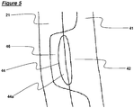
- the fastening point comprises a tab 42 having an opening 44 and a loop section 46.
- the pre-formed inner bag is positioned between the two layers of material that form the outer bag 20.
- the tabs 42 are located such that the loop section 46 and the outer region 44a of the aperture 44 are within the region that will become the welded portion 21 of the outer bag 20.
- the two layers of the outer bag 20 weld together through the outer region 44a of the aperture 44, thereby encapsulating the loop section 46 within the welded portion 21.
- the inner bag 40 is therefore securely fastened to the outer bag 20 even where the material of the inner bag 40 and the outer bag 20 do not weld strongly to one another.
Landscapes
- Health & Medical Sciences (AREA)
- Veterinary Medicine (AREA)
- Public Health (AREA)
- General Health & Medical Sciences (AREA)
- Animal Behavior & Ethology (AREA)
- Life Sciences & Earth Sciences (AREA)
- Hematology (AREA)
- Heart & Thoracic Surgery (AREA)
- Pharmacology & Pharmacy (AREA)
- Biomedical Technology (AREA)
- Anesthesiology (AREA)
- Engineering & Computer Science (AREA)
- Vascular Medicine (AREA)
- External Artificial Organs (AREA)
Claims (13)
- Flüssigkeitskonzentrierungsvorrichtung (200) zum Konzentrieren von Flüssigkeiten, die Teilchenmaterial umfassen, das in einem flüssigen Medium dispergiert ist, durch Entfernung eines Anteils des flüssigen Mediums, wobei die Vorrichtung einen äußeren Beutel (20), der aus einem undurchlässigen Material gebildet ist, und einen inneren Beutel (40) umfasst, der aus einem durchlässigen Material gebildet ist, dadurch gekennzeichnet, dass die Vorrichtung einen Anschluss (22) in dem äußeren Beutel zum Einleiten von Flüssigkeit in die Öffnung zwischen dem äußeren Beutel (20) und dem inneren Beutel (40) umfasst, wobei es das durchlässige Material dem flüssigen Medium, nicht jedoch dem Teilchenmaterial, ermöglicht, in den inneren Beutel (40) einzudringen, und wobei der innere Beutel (40) ein Füllmaterial (60) enthält und zur Verbindung mit einer Unterdruckquelle angepasst ist.
- Flüssigkeitskonzentrierungsvorrichtung (200) nach Anspruch 1, wobei der innere Beutel (40) über eine Leitung (54) mit der Unterdruckquelle verbunden ist.
- Flüssigkeitskonzentrierungsvorrichtung (200) nach einem der vorherigen Ansprüche, wobei der innere Beutel (40) an dem äußeren Beutel (20) befestigt und in diesem abgehängt ist.
- Flüssigkeitskonzentrierungsvorrichtung (200) nach einem der vorherigen Ansprüche, wobei die Materialien des inneren und äußeren Beutels (40, 20) flexibel sind.
- Flüssigkeitskonzentrierungsvorrichtung (200) nach einem der vorherigen Ansprüche, wobei die Materialien des inneren und äußeren Beutels (40, 20) wärmeschweißbar sind.
- Flüssigkeitskonzentrierungsvorrichtung (200) nach Anspruch 5, wobei der innere Beutel (40) und der äußere Beutel (20) aus zwei Materialbahnen gebildet sind, die durch Wärmeschweißen um ihre Enden aneinander befestigt sind.
- Flüssigkeitskonzentrierungsvorrichtung (200) nach einem der vorherigen Ansprüche, wobei das Material des äußeren Beutels (20) Polyvinylchlorid ist.
- Flüssigkeitskonzentrierungsvorrichtung (200) nach einem der vorherigen Ansprüche, wobei das Material des inneren Beutels (40) eine poröse Polycarbonatmembran ist.
- Flüssigkeitskonzentrierungsvorrichtung (200) nach einem der vorherigen Ansprüche, wobei die Poren des inneren Beutels (40) einen Durchmesser von zwischen 0,01 µm und 1 mm oder zwischen 0,01 µm und 5 µm oder zwischen 0,1µm und 2 µm oder etwa 1 µm aufweisen.
- Flüssigkeitskonzentrierungsvorrichtung (200) nach Anspruch 3, wobei der innere Beutel (40) an der inneren Wand des äußeren Beutels (20) an einem oder mehreren Befestigungspunkten befestigt ist.
- Flüssigkeitskonzentrierungsvorrichtung (200) nach Anspruch 10, wobei die einen oder mehreren Befestigungspunkte aus einer Lasche (42) bestehen, die von der Kante des inneren Beutels (40) hervorsteht und sandwichartig zwischen den zwei Schichten des äußeren Beutels (20) aufgenommen ist, wo diese zusammengeschweißt sind.
- Flüssigkeitskonzentrierungsvorrichtung (200) nach Anspruch 11, wobei jede Lasche (42) eine oder mehrere Öffnungen (44) aufweist.
- Verfahren zum Verarbeiten von Blut, wobei das Verfahren die folgenden Schritte umfasst:(i) Einleiten von Blut in die Öffnung zwischen dem äußeren Beutel (20) und dem inneren Beutel (40) der Flüssigkeitskonzentrierungsvorrichtung (200) nach einem der Ansprüche 1 bis 12; und(ii) Ausüben einer Druckdifferenz über das durchlässige Material des inneren Beutels (40), sodass Blutplasma durch das durchlässige Material gesogen wird.
Applications Claiming Priority (4)
| Application Number | Priority Date | Filing Date | Title |
|---|---|---|---|
| GBGB0920070.0A GB0920070D0 (en) | 2009-11-17 | 2009-11-17 | Method of processing blood |
| GBGB0920069.2A GB0920069D0 (en) | 2009-11-17 | 2009-11-17 | Reduced pressure fluid concentrator |
| GBGB0920072.6A GB0920072D0 (en) | 2009-11-17 | 2009-11-17 | Fluid concentrator |
| EP10781993.0A EP2501419B1 (de) | 2009-11-17 | 2010-11-17 | Vorrichtung zur flüssigkeitsverarbeitung |
Related Parent Applications (2)
| Application Number | Title | Priority Date | Filing Date |
|---|---|---|---|
| EP10781993.0A Division EP2501419B1 (de) | 2009-11-17 | 2010-11-17 | Vorrichtung zur flüssigkeitsverarbeitung |
| EP10781993.0A Division-Into EP2501419B1 (de) | 2009-11-17 | 2010-11-17 | Vorrichtung zur flüssigkeitsverarbeitung |
Publications (2)
| Publication Number | Publication Date |
|---|---|
| EP2921187A1 EP2921187A1 (de) | 2015-09-23 |
| EP2921187B1 true EP2921187B1 (de) | 2018-03-21 |
Family
ID=43590472
Family Applications (2)
| Application Number | Title | Priority Date | Filing Date |
|---|---|---|---|
| EP15163927.5A Active EP2921187B1 (de) | 2009-11-17 | 2010-11-17 | Vorrichtung und verfahren zur flüssigkeitsverarbeitung |
| EP10781993.0A Active EP2501419B1 (de) | 2009-11-17 | 2010-11-17 | Vorrichtung zur flüssigkeitsverarbeitung |
Family Applications After (1)
| Application Number | Title | Priority Date | Filing Date |
|---|---|---|---|
| EP10781993.0A Active EP2501419B1 (de) | 2009-11-17 | 2010-11-17 | Vorrichtung zur flüssigkeitsverarbeitung |
Country Status (6)
| Country | Link |
|---|---|
| US (1) | US9254354B2 (de) |
| EP (2) | EP2921187B1 (de) |
| AU (1) | AU2010320670B2 (de) |
| CA (1) | CA2766670C (de) |
| WO (1) | WO2011061533A1 (de) |
| ZA (1) | ZA201200068B (de) |
Families Citing this family (14)
| Publication number | Priority date | Publication date | Assignee | Title |
|---|---|---|---|---|
| GB2509780B (en) * | 2013-01-15 | 2019-08-28 | Brightwake Ltd | Fat Processing Device |
| GB2512841B (en) | 2013-04-08 | 2020-07-15 | Brightwake Ltd | Absorbent wound dressings |
| GB201313137D0 (en) * | 2013-07-23 | 2013-09-04 | Brightwake Ltd | Apparatus for blood concentration |
| US10159778B2 (en) | 2014-03-24 | 2018-12-25 | Fenwal, Inc. | Biological fluid filters having flexible walls and methods for making such filters |
| US9796166B2 (en) | 2014-03-24 | 2017-10-24 | Fenwal, Inc. | Flexible biological fluid filters |
| US9782707B2 (en) | 2014-03-24 | 2017-10-10 | Fenwal, Inc. | Biological fluid filters having flexible walls and methods for making such filters |
| US9968738B2 (en) | 2014-03-24 | 2018-05-15 | Fenwal, Inc. | Biological fluid filters with molded frame and methods for making such filters |
| US10376627B2 (en) | 2014-03-24 | 2019-08-13 | Fenwal, Inc. | Flexible biological fluid filters |
| WO2018111550A1 (en) * | 2016-12-12 | 2018-06-21 | Werd, Llc | A syringe for processing fat grafts and related methods |
| CA3054921A1 (en) | 2017-03-03 | 2018-09-07 | Rich Technologies Holding Company, Llc | Device for preserving blood products and cellular cultures in a gas medium under pressure |
| GB2573265B (en) * | 2018-03-12 | 2022-06-15 | Tsi Tech Limited | Apparatus for treating blood |
| FR3106064B1 (fr) * | 2020-01-14 | 2024-08-09 | Maco Pharma Sa | Système pour l’élimination sélective d’une substance cible dans un fluide biologique |
| JP6848108B1 (ja) * | 2020-06-30 | 2021-03-24 | テルモ株式会社 | 医療用バッグシステム及び遠心分離システム |
| EP4687806A1 (de) * | 2023-04-05 | 2026-02-11 | Rockfield Medical Devices Limited | Modulare pumpe zur enteralen ernährung |
Family Cites Families (34)
| Publication number | Priority date | Publication date | Assignee | Title |
|---|---|---|---|---|
| US3485751A (en) * | 1967-01-06 | 1969-12-23 | Walter L Herrmann | Dialyzer apparatus and method |
| US3742946A (en) | 1970-05-15 | 1973-07-03 | C Grossman | Apparatus for the in vivo treatment of blood containing harmful components resulting from chronic uremia and other conditions |
| SE441143B (sv) | 1976-09-02 | 1985-09-16 | Hoechst Ag | Membranenhet och anordning for avlegsnande av metaboliter ur blod |
| DE2722025A1 (de) | 1977-05-16 | 1978-11-30 | Hoechst Ag | Membraneinheit, vorrichtung mit membraneinheit und verfahren zur blutreinigung |
| GR76226B (de) | 1981-07-22 | 1984-08-04 | Du Pont | |
| US4631050A (en) | 1985-09-24 | 1986-12-23 | Reed Charles C | Autotransfusion system and method |
| FR2600537B1 (fr) | 1986-06-24 | 1990-02-16 | Evelyne Lasnier | Autotransfuseur. |
| US4966758A (en) | 1988-04-15 | 1990-10-30 | Becton, Dickinson And Company | Vacuum ampule filtration device |
| IT1241940B (it) | 1989-11-09 | 1994-02-01 | Grace W R & Co | Dispositivo di multiconcentrazione di liquidi a perdere. |
| US5215519A (en) | 1990-03-07 | 1993-06-01 | Shettigar U Ramakrishna | Autotransfusion membrane system with means for providing reverse filtration |
| US5211850A (en) | 1991-07-26 | 1993-05-18 | Research Medical, Inc. | Plasma filter sorbent system for removal of components from blood |
| JPH0751487B2 (ja) | 1993-05-10 | 1995-06-05 | 上野 素敬 | 抗菌シート及びこのシートを使用したカレンダー |
| GB9422504D0 (en) | 1994-11-08 | 1995-01-04 | Robertson Patricia M B | Blood testing |
| WO1997032653A1 (en) | 1996-03-08 | 1997-09-12 | Baxter Research Medical, Inc. | Selective membrane/sorption techniques for salvaging blood |
| JP2001503656A (ja) | 1996-11-08 | 2001-03-21 | ポール コーポレイション | 血漿を精製する方法およびそれに適する装置 |
| US5876611A (en) | 1997-06-16 | 1999-03-02 | Shettigar; U. Ramakrishna | Intraoperative blood salvaging system and method |
| FR2777786B1 (fr) | 1998-04-27 | 2000-08-11 | Maco Pharma Sa | Poche de filtration destinee a retenir par filtration les constituants cellulaires du plasma,ensemble de poches la contenant. |
| ES2243023T3 (es) | 1998-05-19 | 2005-11-16 | Terumo Kabushiki Kaisha | Metodo de eliminacion de globulos blancos. |
| BRPI0112205B8 (pt) | 2000-07-10 | 2021-06-22 | Asahi Kasei Kuraray Medical Co | filtro de processamento de sangue. |
| FR2814080B1 (fr) | 2000-09-20 | 2003-02-28 | Maco Pharma Sa | Dispositif de filtration a plusieurs milieux filtrants et systeme a poches le comprenant |
| FR2821762B1 (fr) | 2001-03-09 | 2003-11-28 | Maco Pharma Sa | Unite de filtration comprenant deux milieux filtrants distincts et systeme a poches le comprenant |
| JP2005519744A (ja) | 2002-03-14 | 2005-07-07 | バクスター・インターナショナル・インコーポレイテッド | 化合物除去器 |
| FR2842122B1 (fr) | 2002-07-10 | 2004-08-13 | Maco Pharma Sa | Unite de deleucocytation selective d'un produit plaquettaire |
| US7422726B2 (en) | 2002-10-23 | 2008-09-09 | Blood Cell Storage, Inc. | Integrated container for lyophilization, rehydration and processing of biological materials |
| WO2004052270A1 (ja) * | 2002-12-12 | 2004-06-24 | Asahi Kasei Kabushiki Kaisha | ウイルス除去バッグ及びそれを用いたウイルス除去方法 |
| US20040258765A1 (en) | 2003-06-23 | 2004-12-23 | Gee Gilbert C. | Method for treatment of sores and lesions of the skin |
| US20050186183A1 (en) * | 2003-12-08 | 2005-08-25 | Deangelo Joseph | Stabilized products, processes and devices for preparing same |
| US7332096B2 (en) | 2003-12-19 | 2008-02-19 | Fenwal, Inc. | Blood filter assembly having multiple filtration regions |
| TWI242460B (en) | 2003-12-23 | 2005-11-01 | Ind Tech Res Inst | Method and device for separating fibrin glue from blood plasma |
| FR2874327B1 (fr) | 2004-08-19 | 2007-10-05 | Direction Et Priorites Sa Sa | Procede d'autotransfusion et dispositif d'autotransfusion a separation de phases et concentration a poches amovibles |
| WO2006086201A2 (en) | 2005-02-07 | 2006-08-17 | Hanuman Llc | Platelet rich plasma concentrate apparatus and method |
| EP1897570A1 (de) | 2006-09-08 | 2008-03-12 | Gelanus B.V. | Gerät zur Blutrückgewinnung und Verfahren |
| US20090300933A1 (en) * | 2008-06-04 | 2009-12-10 | William Howe | Dispensing vessel for clothes dryer |
| GB0809092D0 (en) * | 2008-05-20 | 2008-06-25 | Univ Strathclyde | Fluid processing device |
-
2010
- 2010-11-17 WO PCT/GB2010/051916 patent/WO2011061533A1/en not_active Ceased
- 2010-11-17 EP EP15163927.5A patent/EP2921187B1/de active Active
- 2010-11-17 EP EP10781993.0A patent/EP2501419B1/de active Active
- 2010-11-17 CA CA2766670A patent/CA2766670C/en active Active
- 2010-11-17 AU AU2010320670A patent/AU2010320670B2/en not_active Ceased
- 2010-11-17 US US13/384,135 patent/US9254354B2/en active Active
-
2012
- 2012-01-05 ZA ZA2012/00068A patent/ZA201200068B/en unknown
Non-Patent Citations (1)
| Title |
|---|
| None * |
Also Published As
| Publication number | Publication date |
|---|---|
| CA2766670C (en) | 2018-07-10 |
| US9254354B2 (en) | 2016-02-09 |
| CA2766670A1 (en) | 2011-05-26 |
| EP2921187A1 (de) | 2015-09-23 |
| ZA201200068B (en) | 2015-07-29 |
| AU2010320670A1 (en) | 2012-02-02 |
| WO2011061533A1 (en) | 2011-05-26 |
| EP2501419A1 (de) | 2012-09-26 |
| EP2501419B1 (de) | 2015-06-03 |
| AU2010320670B2 (en) | 2015-10-29 |
| US20120175319A1 (en) | 2012-07-12 |
Similar Documents
| Publication | Publication Date | Title |
|---|---|---|
| EP2921187B1 (de) | Vorrichtung und verfahren zur flüssigkeitsverarbeitung | |
| KR100743483B1 (ko) | 바이러스 제거 백 및 그것을 이용한 바이러스 제거 방법 | |
| AU2003204942B2 (en) | A selective deleukocytation unit for a platelet product | |
| AU2001269492B2 (en) | Blood processing filter | |
| JP3517359B2 (ja) | 細胞分離・回収装置および細胞の分離・回収方法 | |
| CN1073614A (zh) | 从生物体液分离血浆的方法和装置 | |
| TW201412350A (zh) | 過濾裝置 | |
| WO2010026891A1 (ja) | 血液処理器具 | |
| EP2279239B1 (de) | Behälter mit wirbelbrecher und system dafür | |
| JP2011072816A (ja) | 血液処理フィルター、及び血液の濾過方法 | |
| WO2016047444A1 (ja) | 細胞分離材および細胞分離方法 | |
| JP2006158738A (ja) | 白血球除去システムの遠心方法 | |
| JP4986285B2 (ja) | 白血球除去フィルターを用いた血液または血液成分の濾過方法及び濾過装置 | |
| AU2009248556B2 (en) | Fluid processing device | |
| JP2005237791A (ja) | 血液の濾過方法および血液の濾過システム | |
| AU2003202448A1 (en) | Defibrination bag and method using a textile element | |
| JPH03173824A (ja) | 白血球分離器 | |
| JP4916831B2 (ja) | 血液処理フィルター及び血液処理方法 | |
| JP4130401B2 (ja) | 血液処理フィルター | |
| JP5749123B2 (ja) | 血液処理用フィルター、血液処理システム及び血液製剤の製造方法 | |
| JP2008086352A (ja) | 血液処理フィルター | |
| WO2017179705A1 (ja) | 細胞懸濁液調製用容器および細胞懸濁液の調製方法 | |
| AU2023382179A1 (en) | Fluid filtration apparatus and related methods | |
| JP2011212262A (ja) | 生物学的流体の濾過方法 | |
| JP2011235188A (ja) | 血液処理フィルター |
Legal Events
| Date | Code | Title | Description |
|---|---|---|---|
| PUAI | Public reference made under article 153(3) epc to a published international application that has entered the european phase |
Free format text: ORIGINAL CODE: 0009012 |
|
| AC | Divisional application: reference to earlier application |
Ref document number: 2501419 Country of ref document: EP Kind code of ref document: P |
|
| AK | Designated contracting states |
Kind code of ref document: A1 Designated state(s): AL AT BE BG CH CY CZ DE DK EE ES FI FR GB GR HR HU IE IS IT LI LT LU LV MC MK MT NL NO PL PT RO RS SE SI SK SM TR |
|
| 17P | Request for examination filed |
Effective date: 20160321 |
|
| RBV | Designated contracting states (corrected) |
Designated state(s): AL AT BE BG CH CY CZ DE DK EE ES FI FR GB GR HR HU IE IS IT LI LT LU LV MC MK MT NL NO PL PT RO RS SE SI SK SM TR |
|
| 17Q | First examination report despatched |
Effective date: 20160616 |
|
| STAA | Information on the status of an ep patent application or granted ep patent |
Free format text: STATUS: EXAMINATION IS IN PROGRESS |
|
| GRAP | Despatch of communication of intention to grant a patent |
Free format text: ORIGINAL CODE: EPIDOSNIGR1 |
|
| STAA | Information on the status of an ep patent application or granted ep patent |
Free format text: STATUS: GRANT OF PATENT IS INTENDED |
|
| INTG | Intention to grant announced |
Effective date: 20171005 |
|
| GRAS | Grant fee paid |
Free format text: ORIGINAL CODE: EPIDOSNIGR3 |
|
| GRAA | (expected) grant |
Free format text: ORIGINAL CODE: 0009210 |
|
| STAA | Information on the status of an ep patent application or granted ep patent |
Free format text: STATUS: THE PATENT HAS BEEN GRANTED |
|
| AC | Divisional application: reference to earlier application |
Ref document number: 2501419 Country of ref document: EP Kind code of ref document: P |
|
| AK | Designated contracting states |
Kind code of ref document: B1 Designated state(s): AL AT BE BG CH CY CZ DE DK EE ES FI FR GB GR HR HU IE IS IT LI LT LU LV MC MK MT NL NO PL PT RO RS SE SI SK SM TR |
|
| REG | Reference to a national code |
Ref country code: GB Ref legal event code: FG4D |
|
| REG | Reference to a national code |
Ref country code: CH Ref legal event code: EP |
|
| REG | Reference to a national code |
Ref country code: AT Ref legal event code: REF Ref document number: 980411 Country of ref document: AT Kind code of ref document: T Effective date: 20180415 |
|
| REG | Reference to a national code |
Ref country code: IE Ref legal event code: FG4D |
|
| REG | Reference to a national code |
Ref country code: DE Ref legal event code: R096 Ref document number: 602010049432 Country of ref document: DE |
|
| REG | Reference to a national code |
Ref country code: SE Ref legal event code: TRGR |
|
| REG | Reference to a national code |
Ref country code: NL Ref legal event code: FP |
|
| PG25 | Lapsed in a contracting state [announced via postgrant information from national office to epo] |
Ref country code: NO Free format text: LAPSE BECAUSE OF FAILURE TO SUBMIT A TRANSLATION OF THE DESCRIPTION OR TO PAY THE FEE WITHIN THE PRESCRIBED TIME-LIMIT Effective date: 20180621 Ref country code: CY Free format text: LAPSE BECAUSE OF FAILURE TO SUBMIT A TRANSLATION OF THE DESCRIPTION OR TO PAY THE FEE WITHIN THE PRESCRIBED TIME-LIMIT Effective date: 20180321 Ref country code: LT Free format text: LAPSE BECAUSE OF FAILURE TO SUBMIT A TRANSLATION OF THE DESCRIPTION OR TO PAY THE FEE WITHIN THE PRESCRIBED TIME-LIMIT Effective date: 20180321 Ref country code: HR Free format text: LAPSE BECAUSE OF FAILURE TO SUBMIT A TRANSLATION OF THE DESCRIPTION OR TO PAY THE FEE WITHIN THE PRESCRIBED TIME-LIMIT Effective date: 20180321 Ref country code: FI Free format text: LAPSE BECAUSE OF FAILURE TO SUBMIT A TRANSLATION OF THE DESCRIPTION OR TO PAY THE FEE WITHIN THE PRESCRIBED TIME-LIMIT Effective date: 20180321 |
|
| REG | Reference to a national code |
Ref country code: LT Ref legal event code: MG4D |
|
| REG | Reference to a national code |
Ref country code: AT Ref legal event code: MK05 Ref document number: 980411 Country of ref document: AT Kind code of ref document: T Effective date: 20180321 |
|
| PG25 | Lapsed in a contracting state [announced via postgrant information from national office to epo] |
Ref country code: BG Free format text: LAPSE BECAUSE OF FAILURE TO SUBMIT A TRANSLATION OF THE DESCRIPTION OR TO PAY THE FEE WITHIN THE PRESCRIBED TIME-LIMIT Effective date: 20180621 Ref country code: GR Free format text: LAPSE BECAUSE OF FAILURE TO SUBMIT A TRANSLATION OF THE DESCRIPTION OR TO PAY THE FEE WITHIN THE PRESCRIBED TIME-LIMIT Effective date: 20180622 Ref country code: LV Free format text: LAPSE BECAUSE OF FAILURE TO SUBMIT A TRANSLATION OF THE DESCRIPTION OR TO PAY THE FEE WITHIN THE PRESCRIBED TIME-LIMIT Effective date: 20180321 Ref country code: RS Free format text: LAPSE BECAUSE OF FAILURE TO SUBMIT A TRANSLATION OF THE DESCRIPTION OR TO PAY THE FEE WITHIN THE PRESCRIBED TIME-LIMIT Effective date: 20180321 |
|
| REG | Reference to a national code |
Ref country code: FR Ref legal event code: PLFP Year of fee payment: 9 |
|
| PG25 | Lapsed in a contracting state [announced via postgrant information from national office to epo] |
Ref country code: PL Free format text: LAPSE BECAUSE OF FAILURE TO SUBMIT A TRANSLATION OF THE DESCRIPTION OR TO PAY THE FEE WITHIN THE PRESCRIBED TIME-LIMIT Effective date: 20180321 Ref country code: ES Free format text: LAPSE BECAUSE OF FAILURE TO SUBMIT A TRANSLATION OF THE DESCRIPTION OR TO PAY THE FEE WITHIN THE PRESCRIBED TIME-LIMIT Effective date: 20180321 Ref country code: AL Free format text: LAPSE BECAUSE OF FAILURE TO SUBMIT A TRANSLATION OF THE DESCRIPTION OR TO PAY THE FEE WITHIN THE PRESCRIBED TIME-LIMIT Effective date: 20180321 Ref country code: RO Free format text: LAPSE BECAUSE OF FAILURE TO SUBMIT A TRANSLATION OF THE DESCRIPTION OR TO PAY THE FEE WITHIN THE PRESCRIBED TIME-LIMIT Effective date: 20180321 Ref country code: IT Free format text: LAPSE BECAUSE OF FAILURE TO SUBMIT A TRANSLATION OF THE DESCRIPTION OR TO PAY THE FEE WITHIN THE PRESCRIBED TIME-LIMIT Effective date: 20180321 Ref country code: EE Free format text: LAPSE BECAUSE OF FAILURE TO SUBMIT A TRANSLATION OF THE DESCRIPTION OR TO PAY THE FEE WITHIN THE PRESCRIBED TIME-LIMIT Effective date: 20180321 |
|
| PG25 | Lapsed in a contracting state [announced via postgrant information from national office to epo] |
Ref country code: CZ Free format text: LAPSE BECAUSE OF FAILURE TO SUBMIT A TRANSLATION OF THE DESCRIPTION OR TO PAY THE FEE WITHIN THE PRESCRIBED TIME-LIMIT Effective date: 20180321 Ref country code: AT Free format text: LAPSE BECAUSE OF FAILURE TO SUBMIT A TRANSLATION OF THE DESCRIPTION OR TO PAY THE FEE WITHIN THE PRESCRIBED TIME-LIMIT Effective date: 20180321 Ref country code: SM Free format text: LAPSE BECAUSE OF FAILURE TO SUBMIT A TRANSLATION OF THE DESCRIPTION OR TO PAY THE FEE WITHIN THE PRESCRIBED TIME-LIMIT Effective date: 20180321 Ref country code: SK Free format text: LAPSE BECAUSE OF FAILURE TO SUBMIT A TRANSLATION OF THE DESCRIPTION OR TO PAY THE FEE WITHIN THE PRESCRIBED TIME-LIMIT Effective date: 20180321 |
|
| PG25 | Lapsed in a contracting state [announced via postgrant information from national office to epo] |
Ref country code: PT Free format text: LAPSE BECAUSE OF FAILURE TO SUBMIT A TRANSLATION OF THE DESCRIPTION OR TO PAY THE FEE WITHIN THE PRESCRIBED TIME-LIMIT Effective date: 20180723 |
|
| REG | Reference to a national code |
Ref country code: DE Ref legal event code: R097 Ref document number: 602010049432 Country of ref document: DE |
|
| PLBE | No opposition filed within time limit |
Free format text: ORIGINAL CODE: 0009261 |
|
| STAA | Information on the status of an ep patent application or granted ep patent |
Free format text: STATUS: NO OPPOSITION FILED WITHIN TIME LIMIT |
|
| PG25 | Lapsed in a contracting state [announced via postgrant information from national office to epo] |
Ref country code: DK Free format text: LAPSE BECAUSE OF FAILURE TO SUBMIT A TRANSLATION OF THE DESCRIPTION OR TO PAY THE FEE WITHIN THE PRESCRIBED TIME-LIMIT Effective date: 20180321 |
|
| 26N | No opposition filed |
Effective date: 20190102 |
|
| PG25 | Lapsed in a contracting state [announced via postgrant information from national office to epo] |
Ref country code: SI Free format text: LAPSE BECAUSE OF FAILURE TO SUBMIT A TRANSLATION OF THE DESCRIPTION OR TO PAY THE FEE WITHIN THE PRESCRIBED TIME-LIMIT Effective date: 20180321 |
|
| REG | Reference to a national code |
Ref country code: CH Ref legal event code: PL |
|
| PG25 | Lapsed in a contracting state [announced via postgrant information from national office to epo] |
Ref country code: LU Free format text: LAPSE BECAUSE OF NON-PAYMENT OF DUE FEES Effective date: 20181117 Ref country code: MC Free format text: LAPSE BECAUSE OF FAILURE TO SUBMIT A TRANSLATION OF THE DESCRIPTION OR TO PAY THE FEE WITHIN THE PRESCRIBED TIME-LIMIT Effective date: 20180321 |
|
| REG | Reference to a national code |
Ref country code: BE Ref legal event code: MM Effective date: 20181130 |
|
| REG | Reference to a national code |
Ref country code: IE Ref legal event code: MM4A |
|
| PG25 | Lapsed in a contracting state [announced via postgrant information from national office to epo] |
Ref country code: LI Free format text: LAPSE BECAUSE OF NON-PAYMENT OF DUE FEES Effective date: 20181130 Ref country code: CH Free format text: LAPSE BECAUSE OF NON-PAYMENT OF DUE FEES Effective date: 20181130 |
|
| PG25 | Lapsed in a contracting state [announced via postgrant information from national office to epo] |
Ref country code: IE Free format text: LAPSE BECAUSE OF NON-PAYMENT OF DUE FEES Effective date: 20181117 |
|
| PG25 | Lapsed in a contracting state [announced via postgrant information from national office to epo] |
Ref country code: BE Free format text: LAPSE BECAUSE OF NON-PAYMENT OF DUE FEES Effective date: 20181130 |
|
| PG25 | Lapsed in a contracting state [announced via postgrant information from national office to epo] |
Ref country code: MT Free format text: LAPSE BECAUSE OF NON-PAYMENT OF DUE FEES Effective date: 20181117 |
|
| PG25 | Lapsed in a contracting state [announced via postgrant information from national office to epo] |
Ref country code: TR Free format text: LAPSE BECAUSE OF FAILURE TO SUBMIT A TRANSLATION OF THE DESCRIPTION OR TO PAY THE FEE WITHIN THE PRESCRIBED TIME-LIMIT Effective date: 20180321 |
|
| PG25 | Lapsed in a contracting state [announced via postgrant information from national office to epo] |
Ref country code: MK Free format text: LAPSE BECAUSE OF NON-PAYMENT OF DUE FEES Effective date: 20180321 Ref country code: HU Free format text: LAPSE BECAUSE OF FAILURE TO SUBMIT A TRANSLATION OF THE DESCRIPTION OR TO PAY THE FEE WITHIN THE PRESCRIBED TIME-LIMIT; INVALID AB INITIO Effective date: 20101117 |
|
| PG25 | Lapsed in a contracting state [announced via postgrant information from national office to epo] |
Ref country code: IS Free format text: LAPSE BECAUSE OF FAILURE TO SUBMIT A TRANSLATION OF THE DESCRIPTION OR TO PAY THE FEE WITHIN THE PRESCRIBED TIME-LIMIT Effective date: 20180721 |
|
| P01 | Opt-out of the competence of the unified patent court (upc) registered |
Free format text: CASE NUMBER: UPC_APP_326738/2023 Effective date: 20230524 |
|
| PGFP | Annual fee paid to national office [announced via postgrant information from national office to epo] |
Ref country code: GB Payment date: 20250918 Year of fee payment: 16 |
|
| PGFP | Annual fee paid to national office [announced via postgrant information from national office to epo] |
Ref country code: FR Payment date: 20250918 Year of fee payment: 16 |
|
| PGFP | Annual fee paid to national office [announced via postgrant information from national office to epo] |
Ref country code: NL Payment date: 20251107 Year of fee payment: 16 |
|
| PGFP | Annual fee paid to national office [announced via postgrant information from national office to epo] |
Ref country code: DE Payment date: 20251021 Year of fee payment: 16 |
|
| PGFP | Annual fee paid to national office [announced via postgrant information from national office to epo] |
Ref country code: SE Payment date: 20251111 Year of fee payment: 16 |