EP2923370B1 - Schaltgeräteanordnung - Google Patents
Schaltgeräteanordnung Download PDFInfo
- Publication number
- EP2923370B1 EP2923370B1 EP14700817.1A EP14700817A EP2923370B1 EP 2923370 B1 EP2923370 B1 EP 2923370B1 EP 14700817 A EP14700817 A EP 14700817A EP 2923370 B1 EP2923370 B1 EP 2923370B1
- Authority
- EP
- European Patent Office
- Prior art keywords
- contact piece
- movement
- rated current
- current contact
- switching device
- Prior art date
- Legal status (The legal status is an assumption and is not a legal conclusion. Google has not performed a legal analysis and makes no representation as to the accuracy of the status listed.)
- Not-in-force
Links
- 230000033001 locomotion Effects 0.000 claims description 215
- 230000005540 biological transmission Effects 0.000 claims description 102
- 230000008878 coupling Effects 0.000 claims description 13
- 238000010168 coupling process Methods 0.000 claims description 13
- 238000005859 coupling reaction Methods 0.000 claims description 13
- 239000011810 insulating material Substances 0.000 description 11
- 238000013519 translation Methods 0.000 description 9
- 238000013461 design Methods 0.000 description 8
- 238000006073 displacement reaction Methods 0.000 description 8
- 230000000712 assembly Effects 0.000 description 5
- 238000000429 assembly Methods 0.000 description 5
- 239000007789 gas Substances 0.000 description 5
- 238000000926 separation method Methods 0.000 description 5
- 238000010276 construction Methods 0.000 description 4
- 239000012530 fluid Substances 0.000 description 4
- 230000009467 reduction Effects 0.000 description 4
- 239000004020 conductor Substances 0.000 description 3
- 230000008602 contraction Effects 0.000 description 3
- 230000013011 mating Effects 0.000 description 3
- 230000002028 premature Effects 0.000 description 3
- 238000007493 shaping process Methods 0.000 description 3
- IJGRMHOSHXDMSA-UHFFFAOYSA-N Atomic nitrogen Chemical compound N#N IJGRMHOSHXDMSA-UHFFFAOYSA-N 0.000 description 2
- 230000009471 action Effects 0.000 description 2
- 230000015572 biosynthetic process Effects 0.000 description 2
- 230000000295 complement effect Effects 0.000 description 2
- 230000000694 effects Effects 0.000 description 2
- 239000012777 electrically insulating material Substances 0.000 description 2
- 238000005538 encapsulation Methods 0.000 description 2
- 230000007246 mechanism Effects 0.000 description 2
- 230000002441 reversible effect Effects 0.000 description 2
- 230000001360 synchronised effect Effects 0.000 description 2
- 238000012546 transfer Methods 0.000 description 2
- 230000001960 triggered effect Effects 0.000 description 2
- RYGMFSIKBFXOCR-UHFFFAOYSA-N Copper Chemical compound [Cu] RYGMFSIKBFXOCR-UHFFFAOYSA-N 0.000 description 1
- 229910018503 SF6 Inorganic materials 0.000 description 1
- 230000004913 activation Effects 0.000 description 1
- XAGFODPZIPBFFR-UHFFFAOYSA-N aluminium Chemical compound [Al] XAGFODPZIPBFFR-UHFFFAOYSA-N 0.000 description 1
- 229910052782 aluminium Inorganic materials 0.000 description 1
- 238000013459 approach Methods 0.000 description 1
- 230000004888 barrier function Effects 0.000 description 1
- 230000008901 benefit Effects 0.000 description 1
- 229910010293 ceramic material Inorganic materials 0.000 description 1
- 230000008859 change Effects 0.000 description 1
- 238000006243 chemical reaction Methods 0.000 description 1
- 238000004891 communication Methods 0.000 description 1
- 229910052802 copper Inorganic materials 0.000 description 1
- 239000010949 copper Substances 0.000 description 1
- 230000003247 decreasing effect Effects 0.000 description 1
- 238000012217 deletion Methods 0.000 description 1
- 230000037430 deletion Effects 0.000 description 1
- 230000001419 dependent effect Effects 0.000 description 1
- 238000011161 development Methods 0.000 description 1
- 238000010292 electrical insulation Methods 0.000 description 1
- 150000002148 esters Chemical class 0.000 description 1
- 230000002349 favourable effect Effects 0.000 description 1
- 239000011152 fibreglass Substances 0.000 description 1
- 238000003780 insertion Methods 0.000 description 1
- 230000037431 insertion Effects 0.000 description 1
- 239000012212 insulator Substances 0.000 description 1
- 230000003993 interaction Effects 0.000 description 1
- 239000007788 liquid Substances 0.000 description 1
- 230000007257 malfunction Effects 0.000 description 1
- 238000000034 method Methods 0.000 description 1
- 239000000203 mixture Substances 0.000 description 1
- 229910052757 nitrogen Inorganic materials 0.000 description 1
- 230000008569 process Effects 0.000 description 1
- 230000002250 progressing effect Effects 0.000 description 1
- 229920005989 resin Polymers 0.000 description 1
- 239000011347 resin Substances 0.000 description 1
- 230000004044 response Effects 0.000 description 1
- 239000007787 solid Substances 0.000 description 1
- 230000006641 stabilisation Effects 0.000 description 1
- 238000011105 stabilization Methods 0.000 description 1
- SFZCNBIFKDRMGX-UHFFFAOYSA-N sulfur hexafluoride Chemical compound FS(F)(F)(F)(F)F SFZCNBIFKDRMGX-UHFFFAOYSA-N 0.000 description 1
- 229960000909 sulfur hexafluoride Drugs 0.000 description 1
- 239000013589 supplement Substances 0.000 description 1
- 230000008093 supporting effect Effects 0.000 description 1
- 230000009466 transformation Effects 0.000 description 1
- 230000007704 transition Effects 0.000 description 1
Images







Classifications
-
- H—ELECTRICITY
- H01—ELECTRIC ELEMENTS
- H01H—ELECTRIC SWITCHES; RELAYS; SELECTORS; EMERGENCY PROTECTIVE DEVICES
- H01H33/00—High-tension or heavy-current switches with arc-extinguishing or arc-preventing means
- H01H33/02—Details
- H01H33/025—Terminal arrangements
-
- H—ELECTRICITY
- H01—ELECTRIC ELEMENTS
- H01H—ELECTRIC SWITCHES; RELAYS; SELECTORS; EMERGENCY PROTECTIVE DEVICES
- H01H33/00—High-tension or heavy-current switches with arc-extinguishing or arc-preventing means
- H01H33/02—Details
- H01H33/04—Means for extinguishing or preventing arc between current-carrying parts
- H01H33/12—Auxiliary contacts on to which the arc is transferred from the main contacts
- H01H33/121—Load break switches
- H01H33/123—Load break switches in which the auxiliary contact pivots on the main contact-arm and performs a delayed and accelerated movement
-
- H—ELECTRICITY
- H01—ELECTRIC ELEMENTS
- H01H—ELECTRIC SWITCHES; RELAYS; SELECTORS; EMERGENCY PROTECTIVE DEVICES
- H01H33/00—High-tension or heavy-current switches with arc-extinguishing or arc-preventing means
- H01H33/02—Details
- H01H33/04—Means for extinguishing or preventing arc between current-carrying parts
- H01H33/06—Insulating body insertable between contacts
-
- H—ELECTRICITY
- H01—ELECTRIC ELEMENTS
- H01H—ELECTRIC SWITCHES; RELAYS; SELECTORS; EMERGENCY PROTECTIVE DEVICES
- H01H33/00—High-tension or heavy-current switches with arc-extinguishing or arc-preventing means
- H01H33/02—Details
- H01H33/24—Means for preventing discharge to non-current-carrying parts, e.g. using corona ring
- H01H33/245—Means for preventing discharge to non-current-carrying parts, e.g. using corona ring using movable field electrodes
-
- H—ELECTRICITY
- H01—ELECTRIC ELEMENTS
- H01H—ELECTRIC SWITCHES; RELAYS; SELECTORS; EMERGENCY PROTECTIVE DEVICES
- H01H33/00—High-tension or heavy-current switches with arc-extinguishing or arc-preventing means
- H01H33/02—Details
- H01H33/42—Driving mechanisms
-
- H—ELECTRICITY
- H01—ELECTRIC ELEMENTS
- H01H—ELECTRIC SWITCHES; RELAYS; SELECTORS; EMERGENCY PROTECTIVE DEVICES
- H01H33/00—High-tension or heavy-current switches with arc-extinguishing or arc-preventing means
- H01H33/02—Details
- H01H2033/028—Details the cooperating contacts being both actuated simultaneously in opposite directions
-
- H—ELECTRICITY
- H01—ELECTRIC ELEMENTS
- H01H—ELECTRIC SWITCHES; RELAYS; SELECTORS; EMERGENCY PROTECTIVE DEVICES
- H01H2221/00—Actuators
- H01H2221/008—Actuators other then push button
- H01H2221/016—Lever; Rocker
-
- H—ELECTRICITY
- H01—ELECTRIC ELEMENTS
- H01H—ELECTRIC SWITCHES; RELAYS; SELECTORS; EMERGENCY PROTECTIVE DEVICES
- H01H2221/00—Actuators
- H01H2221/024—Transmission element
-
- H—ELECTRICITY
- H01—ELECTRIC ELEMENTS
- H01H—ELECTRIC SWITCHES; RELAYS; SELECTORS; EMERGENCY PROTECTIVE DEVICES
- H01H3/00—Mechanisms for operating contacts
- H01H3/32—Driving mechanisms, i.e. for transmitting driving force to the contacts
- H01H3/40—Driving mechanisms, i.e. for transmitting driving force to the contacts using friction, toothed, or screw-and-nut gearing
Definitions
- the invention relates to a switching device arrangement with a first contact set, which is movable relative to a second contact set for producing a switching path, wherein the first contact set comprises a first arcing contact piece and a first rated current contact piece, which are movable relative to each other and one with the first rated current contact piece connected kinematic chain to impart a movement on the first rated current contact piece, wherein via a first gear, a relative movement between the first rated current contact piece and the first arcing contact piece is effected.
- Such a switching device arrangement is for example from the document EP 1 124 243 A2 known.
- Another switching device arrangement is from the Korean patent application KR 10-2007-0008041 also known.
- a switching device arrangement which has a first and a second contact set.
- the two contact sets are movable relative to each other to form a switching path.
- the first contact set is equipped with a first arcing contact piece and with a first rated current contact piece, wherein the first rated current contact piece and the first arcing contact piece are movable relative to each other.
- the use of a kinematic chain is provided in order to impart a movement to the first rated current contact piece.
- a gear By means of a gear, a relative movement between the first rated current contact piece and the second rated current contact piece is effected.
- a fork lever is used, by means of which a reversal of motion is enforced.
- the fork lever is engageable with a drive rod of the kinematic chain.
- driving bolts are arranged to retract, if necessary, in a fork opening or strike a fork end.
- the disadvantage of this construction is that the fork lever is not permanently secured Position is located. In the course of a switching movement, conditions occur instead in which the fork lever, free from any driving pin of the drive rod is free to pivot.
- a switching device arrangement with a first contact set and a second contact set is advantageously equipped at least at one contact set, in particular in each case at both contact sets, with an arcing contact piece and a rated current contact piece.
- the first contact set may have a first arcing contact piece and a first rated current contact piece
- the second contact set may have a second arcing contact piece and a second rated current contact piece.
- the first and second arcing contact pieces and first and second rated current contact pieces are formed complementary to each other, so that they can enter into galvanic contacting and a continuous current path can be produced by means of the switching device arrangement.
- the contact sets are arranged to be movable relative to one another, ie, at least one of the contact sets, in particular both contact sets, can be movably positioned.
- the switching device arrangement as a circuit breaker switchgear assembly is given the opportunity, for example, even in case of error z. B. in the event of a short circuit repeatedly interrupt a short-circuit current safely.
- arcing contact pieces and rated current contact pieces it is possible to optimize the rated current contact pieces with regard to their current carrying capacity in order to be able to conduct low-loss currents at low impedances.
- the arcing contact pieces can be optimized in terms of their resistance to thermal influences of switching arcs, in particular of Ausschaltlichtbögen. Accordingly, the arc contact pieces are to contact leading in a power-up first, followed by contacting the rated current contact pieces is provided. Thus Einschaltlichtbögen occur preferably at the arcing contact pieces. In a turn-off, however, a premature opening or separation of the rated current contact pieces is provided, whereby a facilitator current commutated by the Nennstromnapsmaschinebahn on the arc contact flow path and a Ausschaltlichtbogen is preferably performed between the arcing contact pieces after separation of the arcing contact pieces. In order to enable commutation, the first rated current contact piece and the first arcing contact piece or the second rated current contact piece and the second arcing contact piece should each lead permanently to the same electrical potential and be electrically conductively connected thereto.
- the contact sets are mounted axially displaceable, so that a relative movement in the form of an axial movement of at least one of the contact sets is caused.
- the respective rated current contact pieces and arcing contact pieces are arranged coaxially with one another, wherein the contact sets are arranged opposite one another on the front side. It is thus possible, for example, to make an arcing contact piece in the form of a bolt and an opposite arcing contact piece in the form of a bush, so that the arcing contact pieces can be formed by a relative linear movement are contactable or separable from each other.
- the nominal current contact pieces may be formed complementary in shape and be arranged opposite one another at the front side.
- the rated current contact pieces and the arcing contact pieces can be made substantially rotationally symmetrical and can be arranged in each case coaxially to a displacement axis.
- An advantageous embodiment variant may provide that an arcing contact piece of a contact set on the outer shell side is encompassed by a rated current contact piece, so that a contact set is formed substantially rotationally symmetrical and has a compact and moreover dielectrically favorable rounded shape.
- rated current contact pieces on the first contact set a relative movement between a rated current contact piece and an arcing contact piece may be provided. This makes it possible, for example, to provide a leading contact the arcing contact pieces during a switch-on and to generate a lagging separation of the arcing contact pieces during a switch-off. For example, it can be provided that a relative movement between the rated current contact piece and the arcing contact piece of a contact set takes place such that the rated current contact piece is moved with a first movement profile, whereas the second arcing contact piece is moved with a second movement profile.
- the two movement profiles can overlap in such a way that the arcing contact piece is moved at least in sections at a higher speed than the rated current contact piece.
- the first arcing contact piece is additionally moved and an increased contact or contact separation speed of the arcing contact piece against the movement of the first rated current contact piece is forced.
- a movement can be impressed on the first arcing contact piece, so that in a supplement to the common movements of the first rated current contact piece and the first arcing contact piece, a resulting movement on the first arcing contact piece occurs.
- the first rated current contact piece and the second arcing contact piece are deviating from each other movable, wherein a movement of the first rated current contact piece is part of the movement of the first arcing contact piece.
- a forward or lagging of the arcing contact pieces in the above manner can be generated.
- this can cause a rapid dielectric hardening of the switching path, in particular during a turn-off operation.
- the first arcing contact piece in a switch-off process by a superposition of the movements of arcing contact piece and rated current contact piece can be quickly attributed to a field shadow of the first rated current contact piece.
- a base is provided on the switching device arrangement, to which the other moving parts are relatively movable. Accordingly, a reference point can be created on this basis, via which an activation of the first transmission is controlled.
- a fixed positioning of the thrust bearing a fixed reference is given at any time of a switching movement, compared to which, for example the first arcing contact piece can be fixed. A movement emanating from the first arcing contact piece can not lead to a movement on the first transmission, since this is inhibited. Any loosening or moving out, turning over, etc. of the first gear from the stationary counter bearing is prevented.
- a force flow is given between the fixed abutment and the first arcing contact piece, which always defines the position of the arcing contact piece clearly.
- the fixed abutment inhibits a return of the first transmission.
- the arcing contact piece can be fixed relative to the anvil as well as relative to the rated current contact piece in each case in a defined position. Regardless of a switching operation or a movement of the rated current contact piece, a backup of the first transmission can be made via the counter bearing, so that a self-locking drive of the arcing contact piece is given.
- the stationary abutment is able to control the ratio of the relative movements of the rated current contact piece and the first arcing contact piece.
- Both the first arcing contact piece and the first rated current contact piece are movably mounted to the stationary counterbearing.
- the fixed abutment forms a stop to exert an additional force on the first arcing contact piece from a movement of the first rated current contact piece and to force a movement of the first arcing contact piece relative to the second rated current contact piece.
- the fixed abutment forms a stop for a moving part of the first transmission.
- a counterforce can be generated to produce a movement on the first gear.
- An operative connection between the fixed abutment and the first arcing contact allows a movement of the first rated current contact piece as a triggering movement to use for a movement of the first arcing contact piece.
- Drive energy for generating the relative movement between the first rated current contact piece and the first arcing contact piece on the first contact set is coupled out of the movement of the first rated current contact piece.
- the fixed abutment generates a counterforce for a relative to this first movable transmission.
- a gear element can interact with the stationary counter bearing.
- the transmission element can be hinged to the stationary counter-bearing.
- An operative connection for the transmission of forces between a transmission element and the fixed counter bearing can be permanently or temporarily present during a switching movement.
- the stationary abutment controls the transmission behavior of the first transmission.
- the fixed abutment is part of a base to which moving parts of the first contact set are relatively movable.
- the stationary abutment may be formed, for example, as a stop, as a cam, as a bolt, as a gate, as a groove, etc.
- the fixed abutment serves to trigger a movement in response to a relative movement between the first rated current contact piece and fixed counter bearing.
- the transmission behavior of the first transmission can be defined and controlled. It is thus possible, for example, to fix a ratio of the movement of the moving parts (eg first arcing contact piece and first rated current contact piece) to one another by means of an adjustment / special shaping of the fixed counter bearing.
- a transmission element of the first transmission in dependence on the storage of this - gear element and depending on the relative movement of the bearing of the transmission element can be forced into a certain trajectory or through an interaction with the stationary abutment a driving force within the first Gear are constructed so that in addition to a movement of the first rated current contact piece and a movement of the first arcing contact piece, which takes place both relative to the first rated current contact piece and relative to the stationary abutment.
- the abutment can be used to make a superposition of the movements of the first rated current contact piece and the first arcing contact piece in dependence of the progress of a movement of the first rated current contact piece.
- the first arcing contact piece may have an increased speed with respect to the stationary bearing support base relative to the first rated current contact piece.
- the first gear is mounted on the first contact set, in particular on the first rated current contact piece.
- a bearing of the gearbox on the first contact set makes it possible to move the gearbox or the bearing of the gearbox together with it during a movement of the first contact set.
- the first gear is preferably stored stationary on the first set of contacts.
- the first gear may be stationarily mounted on the first rated current contact piece of the first contact set.
- a shaft may be rotatably mounted on the first contact set or on the first rated current contact piece.
- the first contact set, as well as the first rated current contact piece can be constructed in several parts, so that the gear bearing can also be indirectly connected to the first rated current contact piece / the first contact set.
- the anvil thus forms a reference point to use the movement of the first rated current contact piece and to initiate this movement in the first arcing contact piece using the ratio of the first gear and so to force a movement of the first arcing contact piece, which preferably from an addition of the movement of the first gear is impressed on the first arcing contact piece and the movement, which completes the first rated current contact piece emerges.
- a further advantageous embodiment may provide that the first rated current contact piece is movably mounted relative to the fixed abutment.
- the first rated current contact piece should be movably mounted relative to the stationary abutment, so that in addition a relative movement between the stationary abutment and the first arcing contact piece can take place.
- the first rated current contact piece which is also arranged movable relative to the fixed abutment, so the stationary abutment can be used as a deflection point or as a reference for generating an additional movement of the first arcing contact piece.
- the first rated current contact piece for example, relative to a base, which has the fixed abutment, be movably mounted.
- the first rated current contact piece can be positioned axially displaceable.
- the first arcing contact piece can also be mounted to be axially displaceable, with the displacement axes preferably being arranged congruently or in parallel.
- both the first rated current contact piece and the first arcing contact piece of the first contact set with respect to the fixed thrust bearing are designed to be movable.
- both the first rated current contact piece and the second arcing contact piece with a progress of a movement in each of their positions, which are traversed during an on or off operation be fixed.
- the first gear sets the relative position of the first arcing contact piece and second rated current contact piece depending on the position of the first rated current contact piece.
- the relative position is additionally determined by operative connection of the first gear to the stationary bearing point relative to the base. Accordingly, the positions of the first rated current contact piece and the first arcing contact piece are fixed to one another and in each case to the stationary bearing point.
- a control of the first transmission may, for example, be in operative connection with the stationary counter bearing.
- the control can be executed in one or more parts. For example, by means of the control element, a force connection between the fixed abutment and the movable first arcing contact piece or first rated current contact piece can be forced and a driving force can be introduced into the first arcing contact piece. This creates a mechanical connection between the first contact set or the first arcing contact piece or the first rated current contact piece, so that a backup of the individual movement positions, in particular of the first arcing contact piece, can be made via the control element.
- the first gear inhibits free movement of the first arcing contact piece.
- the control it is possible to transmit an impressed example on the first rated current contact piece movement in the mounted on the rated current contact piece first gear and to develop a force on the first arcing contact piece to a base (the stationary abutment).
- a desired transmission of the movement through the first transmission can be achieved.
- the control can be executed in the form of a spur gear with corresponding teeth, so that a reduction of a relative movement of the rated current contact piece is carried out.
- a reversal of a movement direction can be provided on the control, so that, for example, opposing movements between the first rated current contact piece and the first arcing contact piece can be triggered.
- the control cooperate with the fixed abutment such that, depending on the progress of a movement of the rated current contact piece, the arcing contact piece is moved with a certain movement profile in the course of a switching movement.
- the arc contact piece can first be driven at a low speed (optionally remain at rest relative to the first rated current contact piece) and driven at high speed during an intermediate phase , As a result, a rapid retraction of the first arcing contact piece is effected in a shape-complementary arcing contact piece.
- a speed reduction for example, a bouncing of the arcing contact pieces and thus a premature wear.
- control is permanently in operative connection with the stationary counter bearing. It may also be provided that the stationary counter bearing is only temporarily in engagement with the control element. For example, may be present during a switching operation in dependence on the progress of a switching movement, a continuous connection, so that a guide of the control takes place at the fixed abutment. However, it can also be provided that only a temporary leadership of the control takes place on the abutment.
- control element is designed, for example, in the form of a deflecting element, which engages only temporarily with the stationary counterbearing is, for example, only at the beginning, only to the end or even only during a central portion of a switching movement.
- a permanent bond between fixed abutment and control is given for example by a rotary joint.
- a permanent connection / guidance of the control element with the abutment can be provided (temporarily) exposure of a transfer function (for example, by the use of dead time elements).
- the stationary abutment is coupled to the first gear via a sliding gear.
- the stationary counter bearing and the control element can be connected to one another, for example, via a scannable sliding passage.
- the slide gate can be located, for example, on the control.
- the control may have a fork lever.
- An equipment of the fixed abutment or the first gear with a sliding gate makes it possible to equip the operative connection between the first gear and stationary thrust bearing with a variable transmission behavior.
- a sliding gear is, for example, a path to be scanned or detected by a control element of the first transmission. It can also be provided that the sliding gear is arranged on a transmission element, in particular a control element of the first transmission, which in turn is scanned by the stationary counter bearing.
- the sliding gear for example in the form of a cam, a groove, a thread, etc. may be formed.
- the link gear for example, cause a stronger or weaker gear ratio on the first gear.
- the sliding gear can have so-called dead time ranges, in which as far as possible no movement is transmitted from the first gear to the first arcing contact piece.
- it may also be provided that by a corresponding shaping and position of the sliding gear gain of the Translation of the transmission or a reduction of the ratio of the first transmission takes place.
- the sliding gear has a radical recess, in which engages a control of the first transmission. For example, this control can scan the recess bounding cheeks.
- the slide passage is formed in the form of a groove through which a sliding block can be moved through, the sliding block with the first gear, respectively, whose control should be in communication.
- a sliding gear on a control can be provided which is scanned by the abutment.
- a further advantageous embodiment may provide that the first transmission has a pivoting element, which is hinged on the first rated current contact piece pivotally.
- a pivoting element of the first transmission is advantageously rotatably struck on the first rated current contact piece, so that a pivot point of the pivoting element is moved together with the rated current contact piece.
- the stationary pivot point is thus arranged to be movable relative to the stationary counter contact together with the rated current contact piece.
- the pivoting element it is possible to set a translation behavior on the first transmission due to the design example of swivel arms or swivel radii.
- the pivoting element can, for example, itself serve as a control element or as part of a control element, so that the pivoting element is indirectly or directly coupled to the stationary counterbearing.
- pivoting element In a linearly displaceable mounting of the first rated current contact piece and a pivotally mounted thereon pivoting element is this in cooperation with the stationary abutment in the enforcement of a switching movement of the first rated current contact piece to put into a pivoting movement.
- This is advantageous by a relative mobility of stationary abutment and pivot point of the pivot element causes the first rated current contact piece.
- a reversal of movement compared to the first rated current contact piece on the first arcing contact piece or with respect to the fixed abutment a total increased speed at the first arcing contact piece can be achieved. This is particularly advantageous when the movement of the first rated current contact piece is used to initiate a drive force in the first gear and transform there about this movement and to transmit additional movement to the arcing contact piece.
- the first transmission has a lever arrangement.
- a lever assembly is a mechanically simple construction to adjust the gear ratio on the first gear.
- the lever arrangement may for example be designed in the form of a one- or two-armed lever. By varying the effective lengths of the lever arms on the lever arrangement, in addition to a directional transformation, it is also possible to carry out a speed conversion with the lever arrangement.
- a lever arrangement may be in the form of a two-armed lever or in the form of a one-armed lever.
- the lever arrangement can also have angle levers, for example S-shaped levers, L-shaped levers or Z-shaped levers.
- a gear can be seen, on which, for example, racks or the like attack.
- the lever arrangement can serve as a pivoting element.
- the pivoting element can be embodied, for example, as a one-armed lever, two-armed lever, rotating or pivotably arranged toothed wheel, friction wheel, cable wheel, etc.
- a further advantageous embodiment can provide that the kinematic chain has a second transmission for coupling in a movement onto the first rated current contact piece.
- a kinematic chain has a number of transmission elements to transmit motion from a source to a sink.
- the kinematic chain can be constructed in various ways.
- drive rods, drive chains, drive spindles, hydraulic and pneumatic transmitters, etc. may be provided in the kinematic chain.
- the kinematic chain thus connects, for example, a drive device to which z. B. electrical energy is converted into mechanical energy, said drive energy is converted into a movement on the first rated current contact piece and transmitted.
- the kinematic chain defines the transmission path from the drive device to the first rated current contact piece.
- the use of a second transmission within this kinematic chain makes it possible to adjust the movement of the rated current contact piece via the second transmission.
- the second transmission may be a lever mechanism with fixed lever arms or variable lever arms.
- the second transmission may be, for example, a gear transmission, a friction gear, a belt transmission, a chain transmission, etc.
- the second transmission is mounted stationary.
- a stationary mounting of the second transmission makes it possible to couple with respect to the fixed abutment movement on the rated current contact piece, wherein due to the stationary mounting of the second transmission and the stationary mounting of the fixed abutment on the same base of Switching device arrangement a defined movement is enforced on the first rated current contact piece and as a result also on the first arcing contact piece.
- a defined movement is enforced on the first rated current contact piece and as a result also on the first arcing contact piece.
- the first gearbox should be stationarily mounted with respect to the first rated current contact piece on the rated current contact piece and be movable together with this.
- the second gear should be stationary at the base, on which also the stationary abutment is positioned, be stored.
- a possibility is given to provide a simple way of movement of both the first rated current contact piece and the first arcing contact piece, wherein rated current contact piece and arcing contact piece with mutually different motion profiles are movable.
- the movements which are initiated by the first or the second gear can overlap and thus lead to a speed-increased switching on or off movement of the first arcing contact piece with respect to the first rated current contact piece.
- a further advantageous embodiment can provide that the kinematic chain has an electrically insulating transmission element.
- an electrically insulating transmission element prevents the occurrence of a continuous short-circuit current path via the kinematic chain. For example, it is possible for the kinematic chain to connect areas on the switchgear assembly that carry different electrical potentials.
- the electrically insulating transmission element separates these electrical potentials from each other and prevents the formation of a shorting bridge.
- an electrically insulating transmission element for example, electrically insulating rods, electrically insulating sleeves, electrically insulating straps, etc. find use.
- the kinematic chain represents a connection between the first contact set and the second contact set and thus spans a switching path between the two contact sets.
- an electrically insulating element in the region of the switching path shorting of the switching path is prevented.
- the emergence of stray current paths in the kinematic chain can be prevented by the insertion of an electrically insulating transmission element.
- discharges that might occur, for example, within the kinematic chain can be suppressed.
- rotatably interconnected elements may tend to build up changing electrical potentials such that discharge phenomena may occur in the region of a joint gap.
- An electrically insulating transmission element can counteract the emergence of discharge phenomena.
- a further advantageous embodiment can provide that the electrically insulating transmission element is an insulating nozzle projecting into the switching path.
- An insulating material nozzle is used to serve in the switching path of a guide of switching gases.
- a guide of switching gases For example, be provided that the arc generated due to its thermal properties heated gas in the switching path.
- an insulating nozzle is used. This directs the switching gas in non-critical areas, so that a safe switching off and thus safe deletion of a switching arc is possible.
- a further advantageous embodiment can provide that the two contact sets are driven by a common drive device.
- a common drive unit makes it possible in a simple manner to synchronize the movements on the first or the second set of contacts to one another and thus to effect an exact retraction or extension of the contact pieces. Furthermore, a movement can be effected by the use of a kinematic chain both on the one contact side and on the other contact side of the contact gap.
- gearboxes for example a first and a second gearbox, makes it possible, despite the use of one and the same drive device, to apply different movement profiles to different contact pieces.
- the use of an electrically insulating transmission element within the kinematic chain is advantageous, since a short-circuit bridge between the first contact set and the second contact set is thus avoided.
- a further advantageous embodiment can provide that the first transmission and the second transmission is arranged in the direction of force flow behind one another.
- first and second gearbox When in power flow direction behind one another arrangement of first and second gearbox, it is possible, for example, a movement, for example from the kinematic Coupling chain in the second gear, convert it in the second gear and optionally apply to a first rated current contact piece and use the output from the second gearbox movement as an input of the first transmission, reshape them in the first gear and in turn impose as output on the first arcing contact piece.
- the possibility is given to synchronize the movements on the first contact set relative to each other and cause almost any number of repetitions of the sequence of movements with a low cost.
- the mechanical coupling given the assurance that in case of failure of the drive device is a complete stop both on the first and on the second gear.
- a relative mobility of the transmission to each other makes it possible to decouple a movement at each of the transmission, wherein one of the movements may result from a composition of individual movements of the transmission.
- the second transmission has a stationary mounted rotational element.
- a stationary mounted rotary member is for example fixedly positioned on the base, on which also the stationary abutment is arranged.
- rotation elements various devices can be used.
- a rotary bearing of a shaft of the rotary element should be arranged at a fixed angle to the stationary bearing point.
- a further advantageous embodiment can provide that the rotation element is a gear.
- a gear wheel makes it possible, for example by the use of several coupled on a shaft gears in a simple manner to generate a translation in the second transmission, so that input and output movements differ on the second gearbox. It can also be provided that a toothed wheel is formed only in sections, for example in the form of a circular sector, so that a pivoting movement about the pivot angle of the circular sector can be performed. Thus, for example, be provided that by means of racks a coupling or decoupling of movement is made possible on / from the pivoting element.
- the rotation element is a pivot lever.
- a pivot lever may be, for example, a one- or two-armed lever, are struck on the connecting rods.
- the pivot lever is designed at least with a pivoting arm in the form of a sliding cam, wherein the effective length of a lever arm varies depending on the completion of a movement of the pivoting element.
- a pivoting arm in the form of a sliding cam, wherein the effective length of a lever arm varies depending on the completion of a movement of the pivoting element.
- a larger ratio can be provided on the first transmission than at the end of a pivoting movement of the pivoting element.
- a further advantageous embodiment may provide that one of the transmission, in particular the second transmission, a driving movement in an oppositely driven movement transforms and the other transmission, in particular the first transmission, the opposing movement reinforced.
- the second transmission to reverse a sense of motion of a coupled motion
- the possibility is given, for example, when using a common drive to drive the first and the second contact set to generate an opposite movement between the two contact sets.
- the rated current contact pieces takes place and a switch-off a synchronized removal of the rated current contact pieces is provided from each other.
- the basic movement of the rated current contact pieces by driving at least the first arcing contact piece via the first gear before or after the first arcing contact piece against the first rated current contact piece can be forced.
- the arcing contact pieces of the first and second contact sets are movable relative to each other at a higher contacting speed or contract separating speed than the rated current contact pieces of the first and second contact set.
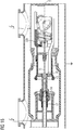
- FIGS. 1 to 16 are different embodiments of Heidelbergierian füren darg Hor.
- the switching device arrangements are constructed in principle similar.
- the respective functional assemblies eg gearboxes
- the differently designed functional modules can be exchanged with each other in the individual variants of the switching device arrangements.
- FIGS. 1 to 5 First, the basic structure and the basic operation of a switching device arrangement will be described in a first embodiment.
- the fifth embodiment variant shown differ in terms of the design of individual functional assemblies, whereby function and structure are fundamentally preserved. Individual functional assemblies (eg gears) of the different variants are interchangeable.
- the in the FIG. 1 shown first embodiment of a switching device arrangement has an encapsulating 1.
- the encapsulating housing 1 is formed from electrically conductive materials, the encapsulating housing itself being grounded. However, it can also be provided that the encapsulating housing is at least partially or completely formed from an electrically insulating material.
- the encapsulating housing 1 forms a barrier around an internal volume to enclose an electrically insulating fluid within the encapsulating housing 1.
- This electrically insulating fluid should preferably be in a gaseous state.
- the interior of the encapsulating housing 1 is filled with an insulating liquid such as an insulating oil or an insulating ester.
- an insulating liquid such as an insulating oil or an insulating ester.
- the encapsulating housing 1 is to be designed as a pressure vessel which withstands a differential pressure between the interior and the exterior of the encapsulation housing 1.
- atmospheric air is located, which is under atmospheric pressure.
- an interrupter unit of the switching device arrangement is arranged within the encapsulating housing 1 within the encapsulating housing 1 within the encapsulating housing 1 arranged.
- the interrupter unit is electrically isolated from the encapsulating housing 1 supported.
- solid insulators can be used, which cause a supporting effect against the encapsulating 1.
- FIG. 1 For reasons of clarity, an illustration of the support of the interrupter unit in the interior of the encapsulating housing 1 has been dispensed with.
- a single interrupter unit or a plurality of mutually electrically isolated interrupter units are arranged in the interior of the encapsulating housing 1.
- a plurality of interrupter units are arranged within a common encapsulating housing, which serve to switch several phases of a polyphase electrical energy transmission system.
- a single interrupter unit within a single encapsulating housing 1 (as in Fig. 1 shown)
- a plurality of encapsulating housings 1 are provided with a plurality of breaker units to form a switchgear assembly, which can also switch multiphase electric power transmission systems.
- the interrupter unit as in the FIG. 1 ff., is an interrupter unit of a high-voltage circuit breaker which serves to interrupt an electric current.
- the interrupter unit according to the FIG. 1 ff. serves to interrupt or produce a current path.
- the interrupter unit has a switching path 2.
- the switching path 2 divides the interrupter unit into a first contact side 3 and a second contact side 4.
- the two contact sides 3, 4 are arranged substantially coaxially to a longitudinal axis 5.
- the two contact sides 3, 4 each have parts of the current path to be interrupted, wherein the electrically conductive parts of the respective contact sides 3, 4 preferably permanently lead to the same electrical potential.
- the two contact sides 3, 4 are electrically isolated from each other, so that over the switching path 2, a potential difference can be kept electrically isolated.
- the first contact side 3 is connected to a first connecting line 6.
- the second contact side 4 is connected to a second connecting line 7.
- the two connection lines 6, 7 are each electrically insulated via jacket side arranged in the encapsulating housing 1 nozzle through a wall of the encapsulating 1 performed. At the nozzle bushing assemblies not shown in the figures are arranged. It is thus possible to insert a connecting line 6, 7 into the interior of the encapsulating housing 1 through an electrically conductive encapsulating housing 1.
- the first contact side 3 has a first fitting body 8.
- the first fitting body 8 is designed in several parts, wherein the first fitting body 8 is a substantially hollow rotational body, which is aligned coaxially with the longitudinal axis 5.
- the first fitting body 8 In its interior, the first fitting body 8 has a receiving space in which, for example, a transmission can be arranged.
- the interior of the first fitting body 8 is dielectrically shielded, since the first fitting body 8 is formed of an electrically conductive material.
- the first fitting body 8 can also be made in one piece. Connected to the first fitting body 8 is the first connecting line 6, so that an electrical potential can be transmitted to the first fitting body 8 and the first fitting body 8 is part of a switchable current path.
- the first fitting body 8 is mounted stationary and forms a stationary base.
- the second contact side 4 has a second fitting body 9.
- the second fitting body 9 differs in its shape from the first fitting body 8.
- the second fitting body 9 is designed in the same way as the first fitting body 8 in several parts, wherein the second fitting body 9 is preferably formed as a substantially rotationally symmetrical hollow body, which provides a receiving space in its interior.
- the second fitting body 9 should be aligned with its axis of rotation coaxially with the longitudinal axis 5.
- end faces of the first fitting body 8 and the second fitting body 9 should face each other. It can be provided that the mutually facing end faces of the two fitting body 8, 9 are connected to each other via an electrically insulating member 10.
- the electrically insulating component 10 may, for example in the form of one or more insulating rods, a mechanical stiffening between the two valve bodies 8, 9 of the first contact side 3 as well make the second contact page 4.
- the electrically insulating component 10 is arranged, for example in the manner of a pipe coaxial with the longitudinal axis 5, wherein the opposite end faces of such a pipe are respectively connected to the first and the second valve body 8, 9.
- deviating shapes of the electrically insulating component 10 are provided.
- electrically insulating materials for forming the electrically insulating component 10 are, for example, ceramic materials, glass fiber reinforced plastics, insulating resins, etc.
- the two fitting body 8, 9 of the first and the second contact side 3, 4 each limit the outer envelope contour of the interrupter unit.
- the two fitting body 8, 9 are arranged rigid angle to each other and form a stationary base.
- the two fitting body 8, 9 are preferably formed of an electrically conductive material, such as aluminum or copper, which on the one hand form a current path portion of the switchable current path and on the other cause mechanical stabilization of the interrupter unit.
- On the first fitting body 8 and on the second fitting body 9, a first contact set 11 and a second contact set 12 are movably mounted.
- the two contact sets 11, 12 are each electrically connected to the respective valve body 8, 9.
- the first contact set 11 has a first rated current contact piece 13.
- the first rated current contact piece 13 is substantially tubular in shape and arranged coaxially with the longitudinal axis 5. Furthermore, the first rated current contact piece 13 is mounted displaceably on the first valve body 8 along the axis 5. The first fitting body 8 thus forms a stationary base for the first rated current contact piece 13. At its end facing the second fitting body 9, the first rated current contact piece 13 is flexible deformable contact fingers 13a equipped. The flexible deformable contact fingers 13a are adapted to drive on a counter-shaped contact piece. Such a counter-shaped contact piece is formed on the second contact arrangement 12 in the form of a substantially tubular second rated current contact piece 14.
- both the first rated current contact piece 13 and the second rated current contact piece 14 are movably mounted so that the two rated current contact pieces 13, 14 are moved during a switching movement of the interrupter unit of the switching device arrangement.
- the second rated current contact piece 14 is formed substantially rotationally symmetrical and arranged coaxially to the longitudinal axis 5.
- the shell-side cross section of the second rated current contact piece 14 is formed opposite to the flexible contact fingers 13a of the first rated current contact piece 13, so that the contact fingers 13a can slide on the outer shell side of the substantially tubular rated current contact piece 14.
- the second rated current contact piece 14 is guided longitudinally displaceably in a tubular extension of the second fitting body 9 along the longitudinal axis 5.
- the tubular extension of the second fitting body 9 is designed bead-shaped thickened at its end facing the first fitting body 8, so that a dielectrically shielding shaping in the region of the switching path 2 is achieved.
- a toroidal extension on the first rated current contact piece 13 is provided on the outer circumference of the first rated current contact piece 13 in the region of the flexible contact fingers 13a, which serves for a dielectric shielding of the contact gap 2.
- the first rated current contact piece 13 is assigned a first arcing contact piece 15.
- the first arcing contact piece 15 is designed bolt-shaped and slidably mounted on the first rated current contact piece 13.
- the first rated current contact piece 13 surrounds the first arcing contact piece 15, wherein the first arcing contact piece 15 and the first rated current contact piece 13 are aligned coaxially with one another and with respect to the longitudinal axis 5.
- the first rated current contact piece 13 is equipped with a guide bush 16.
- the second rated current contact piece 14 is equipped with a second arcing contact piece 17.
- the second arcing contact piece 17 has a substantially bush-shaped design and is arranged opposite to the bolt-shaped first arcing contact piece 15.
- the bolt-shaped first arcing contact piece 15 enters the socket opening of the second arcing contact piece 17.
- the second arcing contact piece 17 is arranged coaxially with the longitudinal axis 5 and coaxially with the second rated current contact piece 14. It is provided that the second arcing contact piece 17 has the same electrical potential as the second rated current contact piece 14. In the present case, the second rated current contact piece is rigidly connected to the second arcing contact piece 17.
- the first rated current contact piece 13 and the first arcing contact piece 15 are arranged to be movable relative to one another and permanently lead to the same electrical potential. At the second rated current contact piece 14 a Isolierstoffdüse 18 is posted.
- the insulating material nozzle 18 is attached to the inner side of the second rated current contact piece 14 and surrounds the contact region of the second arcing contact piece 17.
- the Isolierstoffdüse 18 is formed as a rotationally symmetrical body and has a Isolierstoffdüsenkanal, within which also extends part of the switching path 2. In the Isolierstoffdüsenkanal also extends the contact region of the first arcing contact piece 15, wherein the end of the insulating material 18, which projects in the direction of the second valve body 9, in turn, at least partially encompassed by the first rated current contact piece 13.
- an annular coupling element 19 is further arranged.
- a movement of the second rated current contact piece 14 is also transmitted to the insulating material 18.
- the Isolierstoffdüse 18 in turn is coupled to a connecting rod 20, which transmits an axial movement of the insulating 18.
- the connecting rod 20 With its end remote from the insulating nozzle 18 end, the connecting rod 20 is connected to a pivot member 21 of a second transmission.
- the pivoting element 21 and the second gear are fixedly mounted on the first valve body 8. In the present embodiment, it is provided to store a pivot point (shaft bearing) of the pivoting element 21 in an electrically insulated manner via an insulating body 22 on the first fitting body 8.
- the insulating body 22 is formed substantially conical, wherein it is arranged coaxially to the longitudinal axis 5.
- a pivot point of the pivoting element 21 of the second transmission is arranged perpendicular to the longitudinal axis 5.
- the connecting rod 20 is connected to a lever arm of the pivoting element 21, so that a movement of the rated current contact piece 14 in the direction of the longitudinal axis 5 via the insulating material 18 and the hinged to the insulating nozzle 18 connecting rod 20 can be converted into a pivoting movement of the pivot member 21.
- the pivoting element 21 has a sliding cam 23, in which a bolt engages. The bolt, which engages in the slide passage 23, is aligned transversely to the longitudinal axis 5 and displaceable in the direction of the longitudinal axis 5.
- the engaging in the slide passage 23 bolt is connected at a fixed angle with a sleeve 24 of the first rated current contact piece 13.
- the sleeve 24 forms with the first rated current contact piece 13 a rigid angle unit.
- an axial movement of the second rated current contact piece 14 via the connecting rod 20, the pivot member 21 and the sliding gear 23 to convert into a pivoting movement and in turn to transform this pivotal movement in a linear movement of the sleeve 24 and the first rated current contact piece 13.
- the second gear with the pivot member 21 thus shapes the outgoing from the second rated current contact piece 14 linear movement in a linear movement with a reverse direction sense. Due to the shape of the sliding gear 23, this is associated with a reduction of the movement, so that the opposing movement, which is transmitted to the first rated current contact piece 13, has a relation to the movement profile of the second rated current contact piece 14 varying movement profile.
- the first fitting body 8 is equipped with an auxiliary console 25.
- the auxiliary console 25 of the first fitting body 8 as well as the first fitting body 8 itself forms a stationary counter bearing.
- a linear sliding passage 26 is arranged, in which guide elements of the sleeve 24 engage, so that a linear displaceability of the sleeve 24 is given.
- the guide elements can be designed as a bolt, which protrude into one and the same cam gear 26 and are spaced from each other. Accordingly, the two bolts are stops, so that the axial displaceability of the sleeve 24 (and thus of the first rated current contact piece 13) is limited.
- two parallel sliding surfaces 27, 28 are arranged, which are aligned in opposite directions and in alignment with the longitudinal axis 5.
- a hammer head 29 of the first arcing contact piece 15 is arranged.
- the hammer head 29 scans the two sliding surfaces 27, 28 and guides the first arcing contact piece 15 together with the guide bush 16 and ensures a linear movement of the first arcing contact piece 15 along the longitudinal axis 5.
- a second transmission is provided to a relative movement of the first arcing contact piece 15 to force the first rated current contact piece 13, a second transmission is provided.
- the second gear is mounted on the first rated current contact piece 13, in particular on the sleeve 24 of the second rated current contact piece 14.
- a pivot point is posted, in which a pivoting element in the form of a fork lever 30 is movable.
- the fork lever 30 protrudes freely with its fork end into the space, wherein the fork end of the fork lever 30 is adapted to engage with a stationary counter-bearing 31.
- the fork end acts as a sliding gate.
- the fixed abutment 31 is designed in the form of a bolt which is aligned perpendicular to the longitudinal axis 5 aligned with the auxiliary console 25.
- With its second end of the fork lever 30 is slidably guided in a slot 29 of the hammer head 29.
- the slot of the hammer head 29 is aligned substantially transversely to the longitudinal axis 5, so that an overstroke of the fork lever 30 can be compensated.
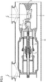
- FIGS. 1 . 2 . 3 . 4 and 5 an overpass in the FIG. 1 shown switching device arrangement of its off position ( Fig. 1 ) into its closed position ( Fig. 5 ) to be discribed.
- a movement of the second rated current contact piece 14 and the second arcing contact piece 17 by a in the FIG. 1 the insulating material 18 is moved and this transmits its linear movement via the connecting rod 20 to the pivot member 21 of the second transmission.
- About the pivotal movement of the pivot member 21 of the second transmission movement is transmitted to the first rated current contact piece 13.
- the Isolierstoffdüse 18 thus bridges electrically isolated the switching path between the two contact sides 3, 4 and acts as an electrically insulating element in a kinematic chain, which serves to cause a movement of the first rated current contact piece 13.
- the contacting speed is increased by the oppositely directed movement of the first rated current contact piece 13.
- the annular coupling element 19 is connected to the insulating material nozzle 18, the annular coupling element 19 is moved together with the insulating material 18. Due to the rotatable mounting of the pivoting element 30 on the first rated current contact piece 13, the first gear is moved along with the movement of the first rated current contact piece 13.
- the fixed abutment 31 located on the auxiliary console 25 slides in the form of a bolt through the fork end of the fork lever 30.
- the fork lever 30 is moved past the stationary abutment 31 and reversed by the operative connection between stationary abutment 31 and the first transmission. Accordingly, due to the connection of the fork lever 30 with the hammer head 29 of the first arcing contact piece 13, the relative movement of the fixed abutment 31 is converted to the first rated current contact piece 13 in a movement of the first arcing contact piece 15.
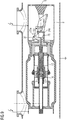
- FIG. 2 In the FIG. 2 is shown a progression of the movement of the second rated current contact piece 14 and the second arcing contact piece 17.
- the Isolierstoffdüse 18 has pushed over the connecting rod 20, the pivot member 21 so far that the first rated current contact piece 13 has already completed a movement from its rest position out.
- the fixed abutment 31 is in engagement with the pivot member 30 of the first transmission.
- a movement of the first arcing contact piece 15, superimposing the movement of the first rated current contact piece 13, proceeds.
- FIG. 3 shows a further progression of the relative movement of the rated current contact pieces 13, 14 and the arcing contact pieces 15, 17.
- the serving as a pivoting element fork lever 30 is turned over.
- the two arcing contact pieces 15, 17 have already touched each other. Based on the initial approximation of the two rated current contact pieces 13, 14, a premature contact of the arcing contact pieces 15, 17 is ensured by a superposition of the additional movement of the first arcing contact piece 15.
- the relative movement ie the approach of the rated current contact pieces 13, 14, is continued.
- a further translation of an additional movement on the first arcing contact piece 15 via the first transmission is no longer necessary, since a contacting of the arcing contact pieces 15, 17 is already effected.
- the first gear can be fixed in this position, so that unintentional movement of the first arcing contact piece 15 can not take place.
- the fork of the fork lever 30 acts as a sliding gate. In the further progression of the movement, the countermovement of the first rated current contact piece 13 is further advanced via the second transmission. In the FIG. 4 the moment of contacting the rated current contact pieces 13, 14 is shown. Further progress of the movement of the rated current contact pieces 13, 14 leads to a movement of the second gear in an extended position.
- the bolt of the thrust bearing 31 is still in the fork of the fork lever 30, so that a backup of the position of the position of the first rated current contact piece 13 is given via the first transmission.
- FIGS. 6 . 7 . 8th . 9 and 10 a second embodiment of a switching device arrangement is shown. Except for the design of the first gear, the mode of action and the movement corresponds to the above to the FIGS. 1 to 5 Executed. The following is therefore only on the different configuration of the second transmission will be received.
- an alternative embodiment of an auxiliary console 25a and a sleeve 24a is provided.
- the sleeve 24a according to the second embodiment is equipped with a bearing point which lies outside the envelope of the sleeve 24a.
- an L-shaped lever 32 is mounted, which has a first and a second lever arm. With its first lever arm, which is longer than the second lever arm, the L-shaped lever with a slot of the hammer head 29 of the first arcing contact piece 15 is connected.
- the second lever arm which is shorter than the first lever arm of the L-shaped lever 32 is guided in a sliding passage 33 of the auxiliary console 25a.
- the second lever arm is equipped with a bolt which projects into the sliding passage 33 of the auxiliary console 25a.
- the sliding gear 33 is formed stepwise, with a gradation transverse to the longitudinal axis 5, so that at the beginning of a movement of the first rated current contact piece 13 (movement of Fig. 6 to Fig. 7 ) initially no transmission of an additional movement by the first gear on the first arcing contact piece 15 takes place.
- a translation of a movement of the first gear on the stationary counter bearing here the slide passage 33 of the auxiliary console 25a
- FIG. 11 and 12 a development of the second embodiment of a switching device arrangement is shown, wherein the first transmission continues to use an L-shaped Levers 32 (two-armed lever) and the auxiliary console 25a holds, but now varies the configuration of the second transmission.
- the insulating material nozzle 18 is rigidly connected to a first rack 34.
- the first rack 34 is guided linearly displaceable parallel to the longitudinal axis 5, so that a displacement of the insulating material 18 is accompanied by a displacement of the first rack 34.
- Via a first gear 35 of the stationary second gear the linear movement of the first rack 34 is converted into a pivoting movement.
- the first gear 35 and the shaft of the first gear 35 is thus a pivoting element.
- a second gear 36 is provided which has a reduced diameter relative to the diameter of the first gear 35. Via a rigid coupling of the two gears 35, 36, a translation of the output from the first rack 34 movement can be made.
- a second rack 37 couples a tapped by the second gear 36 movement on the first rated current contact piece 13 and on a sleeve 24b of the first rated current contact piece 13.
- the first and the second rack 35, 37 are diametrically opposite to the respective gear 35, 36th arranged in engagement, so that over the pivot member of the second transmission, a reversal of the sense of movement of the insulating material 13 and the second arcing contact piece 17 and the second rated current contact piece 14 takes place.
- the L-shaped lever 32 is inserted on the first gear.
- a pivoting element for example, in the third embodiment according to the Figures 11 and 12 a fork lever 30 as used in the first embodiment.
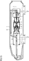
- FIG. 13 shows a third embodiment of a switching device arrangement. Notwithstanding the variants one, two and three after the FIGS. 1 to 12 However, here is the use of the insulating 18 as electrical insulating element in a kinematic chain for driving the first rated current contact piece 13 and the first arcing contact piece 15 is omitted. Instead, a movement is already decoupled via a second gear, which has a pivoting element 38, on the second contact side 4, wherein the stationary base (second valve body 9) of the first contact side 3 and the second contact side 4 (first valve body 8) are used synonymously can. A movement is coupled to the second rated current contact piece 14 and the second arcing contact piece 17.
- the first rated current contact piece 13 and the rod coupled to the pivoting element 38 are connected to one another in an angularly rigid manner, so that the electrically insulating rod and the first rated current contact piece 13 perform the same movement.
- the first rated current contact piece 13 in turn has a sleeve 24c, in which the hammer head 29 of the first arcing contact piece 15 is guided axially displaceably.
- an L-shaped lever 32a is rotatably supported.
- the L-shaped lever 32a is slidably guided with its first lever arm in a sliding passage 33a.
- the sliding gear 33a forms a stationary counter bearing for the first transmission.
- the pivoting element in the form of the L-shaped lever 32 a is guided with its other lever arm in a slot of the hammer head 29 of the first arcing contact piece 15.
- the fixed abutment in the form of the sliding gear 33a causes a formation of an operative connection between the fixed abutment and the first gear.
- the first valve body 8 can be understood, wherein the first valve body 8 and the second valve body 9 are coupled together rigid angle and thus set the same stationary base.
- L-shaped lever 32 Analogous to the deflection of the two and three known from the embodiments L-shaped lever 32 is the L-shaped lever 32a according to the fourth embodiment in operative connection with the stationary abutment in the form of a sliding gear 33a.
- FIGS. 15 and 16 shown fifth embodiment of a switching device arrangement is an alternative to that of the FIGS. 1 . 2 . 3 . 4 . 5 . 6 . 7 . 8th . 9 . 10 . 11 . 12 . 13 and 14 used known first gearboxes.
- the fifth embodiment uses for the first gear lever arrangement with a two-armed lever 32b, which is part of a scissors gear.
- a scissors gear is a lever assembly having a plurality of rotatably coupled together lever, which cause an axial displacement of hinge points of the lever.
- the first gear / lever assembly is fixedly connected to the first contact side 3, in particular to the first rated current contact piece 13.
- a central scissors of the scissors gear which has the two-armed lever 32b is coupled at the ends with other levers, which limit the central scissors.
- the end levers limit the central scissors in the manner of toggle mechanisms.
- two parallelograms are formed, which can vary their internal angles at constant side lengths.
- a crosspoint between levers of the scissors gear is stationary / fixed angle mounted with the first rated current contact piece 13.
- This coupling point should lie on an axis of the linear displacement of the scissors gear.
- the stationarily mounted crosspoint is fixedly connected to the first rated current contact piece 13 of the first contact side 3.
- An end parallelogram-like conclusion of the scissors gear is positioned on the side facing away from the first arcing contact piece 15 side fixed to the first rated current contact piece.
- the first arcing contact piece 15 is connected to the scissors gear (with the parallelogram-like completion of the scissors gear, which faces the first arcing contact piece 15).
- the first arcing contact piece 15 can be coupled in a rotary joint to the scissors gear, since the scissors gear couples a linear movement on the first arcing contact piece 15.
- the scissors gear with the local levers is fixedly connected to the first rated current contact piece 13 and to the first contact side 3.
- at least one of the scissor elements is guided in a control link 34 which is stationarily positioned on an auxiliary console.
- the auxiliary console remains independent of a movement of the rated current contact pieces 13, 14 and the arcing contact pieces 15, 17 are unmoved.
- the scissors gear together with the lever of the scissors gear (due to its stationary mounting on the first rated current contact piece 13) is initially moved with the rated current contact piece 13.
- the control link 34 an extension of the scissors gear is forced in the course of a switch-on, ie, the first arcing contact piece 15 is moved from a disconnected position to a contacting position.
- the stretching of the scissors gear is returned. Based on the movement (on or off movement) of the first rated current contact piece 13, an additional speed-increasing movement is enforced on the first arcing contact piece 15.
- the control link 34 is aligned substantially flush with the axis of movement of the first arcing contact piece 15 and extends the distance between the axis of motion at least partially decreasing, sloping in the direction of the axis of movement of the first rated current contact piece 15.
- the control link is scanned by a lever 32a of the scissors gear, so that scanning hinge point in the control link 34 is moved transversely to the linear displacement axis of the first arcing contact piece 15 and a pivoting of the lever 32 a is forced. Due to the transverse offset results in an extension / contraction of the scissors gear, with hinge points (scissor joints) move linearly.
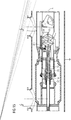
- FIG. 15 is the fifth embodiment of a switching device arrangement shown in closed position, ie, the arcing contact pieces 15, 17 touch each other. Likewise, the rated current contact pieces 13, 14 touch each other.
- the first gear here in the form of a scissors gear, is in an extended position. In an off position according to FIG. 16 the first gear is in the contraction position, so that the rated current contact pieces 13, 14 and the arcing contact pieces 15, 17 are separated from each other.
- a switch-on position Fig. 15
- Fig. 15 a transfer of a switch-on position in an off position
- the second gear corresponds to that in the Figures 11 and 12 illustrated second transmission of the third embodiment.
- the second gear drives the first rated current contact piece 13.
- the stationary mounted on the first rated current contact piece 13 first gear is moved.
- the control link 34 serves as a stationary counter bearing.
- the scissors gear / a control of the first transmission is coupled to the fixed counter bearing.
- first transmission as well as the second transmission according to the fifth embodiment variant can also be used in the further embodiment variants 1, 2, 3 and 4, so that different embodiments of the first transmission as well as different embodiments of the second transmission can be combined with each other as desired.
Landscapes
- Arc-Extinguishing Devices That Are Switches (AREA)
- Contacts (AREA)
- Driving Mechanisms And Operating Circuits Of Arc-Extinguishing High-Tension Switches (AREA)
Description
- Die Erfindung bezieht sich auf eine Schaltgeräteanordnung mit einem ersten Kontaktsatz, welcher zur Herstellung einer Schaltstrecke relativ zu einem zweiten Kontaktsatz bewegbar ist, wobei der erste Kontaktsatz ein erstes Lichtbogenkontaktstück und ein erstes Nennstromkontaktstück aufweist, die relativ zueinander bewegbar sind und mit einer mit dem ersten Nennstromkontaktstück verbundenen kinematischen Kette, um eine Bewegung auf das erste Nennstromkontaktstück aufzuprägen, wobei über ein erstes Getriebe eine Relativbewegung zwischen erstem Nennstromkontaktstück und erstem Lichtbogenkontaktstück bewirkt wird.
- Eine derartige Schaltgeräteanordnung ist beispielsweise aus der Druckschrift
EP 1 124 243 A2 bekannt. - Eine weitere Schaltgeräteanordnung ist aus der koreanischen Schutzrechtsanmeldung
KR 10-2007-0008041 - Somit ergibt sich als Aufgabe der Erfindung, eine Schaltgeräteanordnung anzugeben, welche eine sichere Relativbewegung eines Kontaktsatzes ermöglicht.
- Erfindungsgemäß wird die Aufgabe durch die Schaltgeräteanordnung gemäß dem unabhängigen Anspruch 1 gelöst. Vorteilhafte Ausgestaltungen sind Gegenstand der abhängigen Ansprüche.
- Eine Schaltgeräteanordnung mit einem ersten Kontaktsatz und einem zweiten Kontaktsatz ist vorteilhafterweise zumindest an einem Kontaktsatz, insbesondere jeweils an beiden Kontaktsätzen, mit einem Lichtbogenkontaktstück sowie einem Nennstromkontaktstück ausgestattet. Dabei kann der erste Kontaktsatz ein erstes Lichtbogenkontaktstück und ein erstes Nennstromkontaktstück und der zweite Kontaktsatz ein zweites Lichtbogenkontaktstück und ein zweites Nennstromkontaktstück aufweisen. Die ersten und zweiten Lichtbogenkontaktstücke bzw. ersten und zweiten Nennstromkontaktstücke sind dabei komplementär zueinander ausgeformt, so dass diese in galvanische Kontaktierung treten können und eine durchgängige Strombahn mittels der Schaltgeräteanordnung herstellbar ist. Dabei sind die Kontaktsätze relativ zueinander bewegbar angeordnet, d. h., zumindest einer der Kontaktsätze, insbesondere beide Kontaktsätze, können bewegbar positioniert sein. Somit ist es möglich, bedarfsweise eine elektrische Strombahn über die Schaltgeräteanordnung herzustellen bzw. diese Strombahn bedarfsweise zu unterbrechen. Insbesondere bei Ausgestaltungen der Schaltgeräteanordnung als Leistungsschalter-Schaltgeräteanordnung ist so die Möglichkeit gegeben, beispielsweise auch im Fehlerfall z. B. im Kurzschlussfall wiederholt einen Kurzschlussstrom sicher zu unterbrechen. Durch die Nutzung von Lichtbogenkontaktstücken und Nennstromkontaktstücken ist es möglich, die Nennstromkontaktstücke hinsichtlich ihrer Stromtragfähigkeit zu optimieren, um bei geringen Impedanzen Ströme verlustarm führen zu können. Die Lichtbogenkontaktstücke können hinsichtlich ihrer Widerstandsfähigkeit gegenüber thermischen Einflüssen von Schaltlichtbögen, insbesondere von Ausschaltlichtbögen, optimiert werden. Entsprechend sind bei einem Einschaltvorgang zunächst die Lichtbogenkontaktstücke voreilend zu kontaktieren, worauf folgend ein Kontaktieren der Nennstromkontaktstücke vorgesehen ist. Somit treten Einschaltlichtbögen bevorzugt an den Lichtbogenkontaktstücken auf. Bei einem Ausschaltvorgang hingegen ist ein voreilendes Öffnen bzw. Trennen der Nennstromkontaktstücke vorgesehen, wodurch ein auszuschaltender Strom von der Nennstromkontaktstrombahn auf die Lichtbogenkontaktstrombahn kommutiert und ein Ausschaltlichtbogen nach einer Trennung der Lichtbogenkontaktstücke bevorzugt zwischen den Lichtbogenkontaktstücken geführt ist. Um ein Kommutieren zu ermöglichen, sollte das erste Nennstromkontaktstück und das erste Lichtbogenkontaktstück bzw. das zweite Nennstromkontaktstück und das zweite Lichtbogenkontaktstück jeweils dauerhaft das gleiche elektrische Potential führen und dazu entsprechend elektrisch leitend verbunden sein.
- Besonders vorteilhaft ist es dabei, wenn die Kontaktsätze axial verschieblich gelagert sind, so dass eine Relativbewegung in Form einer Axialbewegung zumindest eines der Kontaktsätze hervorgerufen wird. Vorteilhafterweise kann vorgesehen sein, dass die jeweiligen Nennstromkontaktstücke und Lichtbogenkontaktstücke koaxial zueinander angeordnet sind, wobei die Kontaktsätze einander stirnseitig gegenüberstehend angeordnet sind. So ist es beispielsweise möglich, ein Lichtbogenkontaktstück bolzenförmig und ein gegenüberliegendes Lichtbogenkontaktstück buchsenförmig auszuführen, so dass durch eine relative Linearbewegung die Lichtbogenkontaktstücke kontaktierbar bzw. voneinander trennbar sind. In analoger Weise können auch die Nennstromkontaktstücke formkomplementär ausgebildet sein und einander stirnseitig gegenüberstehend angeordnet sein. Dabei können die Nennstromkontaktstücke und die Lichtbogenkontaktstücke im Wesentlichen rotationssymmetrisch ausgeführt sein und jeweils koaxial zu einer Verschiebeachse angeordnet sein. Eine vorteilhafte Ausführungsvariante kann dabei vorsehen, dass ein Lichtbogenkontaktstück eines Kontaktsatzes außenmantelseitig von einem Nennstromkontaktstück umgriffen ist, so dass ein Kontaktsatz im Wesentlichen rotationssymmetrisch gebildet ist und eine kompakte und darüber hinaus dielektrisch günstige gerundete Formgebung aufweist.
- Darüber hinaus kann zu einer Erhöhung der Kontakttrenngeschwindigkeit bzw. zu einem Steuern der Schaltreihenfolge von Lichtbogenkontaktstücken, Nennstromkontaktstücken am ersten Kontaktsatz eine Relativbewegung zwischen einem Nennstromkontaktstück sowie einem Lichtbogenkontaktstück vorgesehen sein. Dadurch ist es beispielsweise möglich, ein voreilendes Kontaktieren der Lichtbogenkontaktstücke während eines Einschaltvorganges vorzusehen und während eines Ausschaltvorganges ein nacheilendes Trennen der Lichtbogenkontaktstücke zu erzeugen. Beispielsweise kann vorgesehen sein, dass eine Relativbewegung zwischen Nennstromkontaktstück und Lichtbogenkontaktstück eines Kontaktsatzes derart erfolgt, dass das Nennstromkontaktstück mit einem ersten Bewegungsprofil bewegt wird, wohingegen das zweite Lichtbogenkontaktstück mit einem zweiten Bewegungsprofil bewegt wird. Vorteilhafterweise können sich die beiden Bewegungsprofile derart überlagern, dass das Lichtbogenkontaktstück zumindest abschnittsweise mit einer höheren Geschwindigkeit bewegt wird als das Nennstromkontaktstück. So ist es beispielsweise möglich, dass, initiiert von einer Bewegung des Nennstromkontaktstückes, das erste Lichtbogenkontaktstück zusätzlich bewegt wird und eine erhöhte Kontaktierung bzw. Kontaktstrenngeschwindigkeit des Lichtbogenkontaktstückes gegenüber der Bewegung des ersten Nennstromkontaktstückes erzwungen ist. Beispielsweise kann das erste Lichtbogenkontaktstück bei einer Bewegung des ersten Nennstromkontaktstückes mitbewegt werden. Zusätzlich kann eine Bewegung auf das erste Lichtbogenkontaktstück aufgeprägt werden, so dass in einer Ergänzung der gemeinsamen Bewegungen von erstem Nennstromkontaktstück und erstem Lichtbogenkontaktstück eine resultierende Bewegung am ersten Lichtbogenkontaktstück auftritt. Relativ zu einem ortsfesten Gegenlager sind das erste Nennstromkontaktstück und das zweite Lichtbogenkontaktstück abweichend voneinander bewegbar, wobei eine Bewegung des ersten Nennstromkontaktstückes Teil der Bewegung des ersten Lichtbogenkontaktstückes ist. Somit kann zum einen ein Vor- bzw. Nacheilen der Lichtbogenkontaktstücke in oben stehender Art und Weise erzeugt werden. Zum anderen kann dadurch eine schnelle dielektrische Verfestigung der Schaltstrecke, insbesondere bei einem Ausschaltvorgang hervorgerufen werden. Beispielsweise kann das erste Lichtbogenkontaktstück bei einem Ausschaltvorgang durch eine Überlagerung der Bewegungen von Lichtbogenkontaktstück und Nennstromkontaktstück schnell in einen Feldschatten des ersten Nennstromkontaktstückes zurückgeführt werden. Ebenso kann bei einem Einschaltvorgang ein schnelles Heraustreten des ersten Lichtbogenkontaktstückes aus einem Feldschatten des ersten Nennstromkontaktstückes erzielt werden. Somit sind die Übergänge von einem Trennzustand in einen Einschaltzustand und umgekehrt in einer kurzen Zeitspanne auszuführen, so dass befürchtete Feldstärkenüberhöhungen rasch neutralisiert werden und so die Gefahr eines unkontrollierten Entstehens von Entladungserscheinungen an der Schaltgeräteanordnung reduziert ist.
- Durch das Vorsehen eines ortsfesten Gegenlagers für das erste Getriebe ist an der Schaltgeräteanordnung eine Basis geschaffen, zu welcher die weiteren Bewegtteile relativ bewegbar sind. Entsprechend kann an dieser Basis ein Bezugspunkt geschaffen werden, über welchen eine Aktivierung des ersten Getriebes gesteuert wird. Durch eine ortsfeste Positionierung des Gegenlagers ist zu jedem Zeitpunkt einer Schaltbewegung eine feste Bezugsgröße gegeben, gegenüber welcher beispielsweise das erste Lichtbogenkontaktstück fixiert werden kann. Eine von dem ersten Lichtbogenkontaktstück ausgehende Bewegung kann nicht zu einer Bewegung am ersten Getriebe führen, da dieses gehemmt ist. Ein beliebiges Lösen bzw. Herausbewegen, Umschlagen usw. des ersten Getriebes aus dem ortsfesten Gegenlager ist verhindert. Entsprechend ist zwischen dem ortsfesten Gegenlager und dem ersten Lichtbogenkontaktstück ein Kraftfluss gegeben, welcher die Position des Lichtbogenkontaktstückes stets eindeutig definiert. Das ortsfeste Gegenlager hemmt einen Rücklauf des ersten Getriebes. Beispielsweise kann in Abhängigkeit eines Voranschreitens einer Schaltbewegung das Lichtbogenkontaktstück relativ zum Gegenlager als auch relativ zum Nennstromkontaktstück in jeweils einer definierten Position festgelegt sein. Unabhängig von einem Schaltvorgang bzw. einer Bewegung des Nennstromkontaktstückes kann über das Gegenlager eine Sicherung des ersten Getriebes vorgenommen werden, so dass ein selbsthemmender Antrieb des Lichtbogenkontaktstückes gegeben ist. Insbesondere kann in Abhängigkeit eines Voranschreitens einer Bewegung des ersten Nennstromkontaktstückes eine zusätzliche Bewegung des ersten Lichtbogenkontaktstückes bewirkt werden. Das ortsfeste Gegenlager ist dabei in der Lage, das Verhältnis der Relativbewegungen von Nennstromkontaktstück und erstem Lichtbogenkontaktstück zu steuern. Zu dem ortsfesten Gegenlager ist sowohl das erste Lichtbogenkontaktstück als auch das erste Nennstromkontaktstück beweglich gelagert. Das ortsfeste Gegenlager bildet einen Anschlag, um von einer Bewegung des ersten Nennstromkontaktstückes ausgehend eine zusätzliche Kraftwirkung auf das erste Lichtbogenkontaktstück auszuüben und eine Bewegung des ersten Lichtbogenkontaktstückes relativ zum zweiten Nennstromkontaktstück zu erzwingen. Das ortsfeste Gegenlager bildet einen Anschlag für ein Bewegtteil des ersten Getriebes. Am Gegenlager kann eine Gegenkraft erzeugt werden, um eine Bewegung am ersten Getriebe zu erzeugen.
- Eine Wirkverbindung zwischen dem ortsfesten Gegenlager und dem ersten Lichtbogenkontaktstück ermöglicht es, eine Bewegung des ersten Nennstromkontaktstückes als auslösende Bewegung für eine Bewegung des ersten Lichtbogenkontaktstückes zu nutzen. Antriebsenergie zur Erzeugung der Relativbewegung zwischen erstem Nennstromkontaktstück und erstem Lichtbogenkontaktstück am ersten Kontaktsatz wird aus der Bewegung des ersten Nennstromkontaktstückes ausgekoppelt. Das ortsfeste Gegenlager erzeugt eine Gegenkraft für ein relativ zu diesem bewegbares erstes Getriebe. Zum Ausbilden einer Wirkverbindung zwischen dem ersten Getriebe und dem ortsfesten Gegenlager kann ein Getriebeelement mit dem ortsfesten Gegenlager in Wechselwirkung treten. Das Getriebeelement kann beweglich am ortsfesten Gegenlager angeschlagen sein. Eine Wirkverbindung zur Übertragung von Kräften zwischen einem Getriebeelement und dem ortsfesten Gegenlager kann während einer Schaltbewegung dauerhaft oder auch temporär vorhanden sein.
- Weiterhin kann dabei vorteilhaft vorgesehen sein, dass das ortsfeste Gegenlager das Übertragungsverhalten des ersten Getriebes steuert.
- Das ortsfeste Gegenlager ist Teil einer Basis, zu welcher Bewegtteile des ersten Kontaktsatzes relativ bewegbar sind. Das ortsfeste Gegenlager kann beispielsweise als Anschlag, als Nocken, als Bolzen, als Kulisse, als Nut etc. ausgebildet sein. Das ortsfeste Gegenlager dient einer Auslösung einer Bewegung in Abhängigkeit einer Relativbewegung zwischen erstem Nennstromkontaktstück und ortsfestem Gegenlager. Durch ein ortsfestes Gegenlager kann das Übertragungsverhalten des ersten Getriebes definiert und gesteuert werden. So ist es beispielsweise möglich, durch eine Justage/spezielle Ausformung des ortsfesten Gegenlagers auch ein Verhältnis der Bewegung der Bewegtteile (z. B. erstes Lichtbogenkontaktstück und erstes Nennstromkontaktstück) zueinander festzulegen. Beispielsweise kann über das Gegenlager ein Getriebeelement des ersten Getriebes in Abhängigkeit der Lagerung dieses - Getriebeelementes und in Abhängigkeit der Relativbewegung der Lagerung des Getriebeelementes in eine bestimmte Bewegungsbahn gezwungen werden bzw. durch eine Interaktion mit dem ortsfesten Gegenlager eine Antriebskraft innerhalb des ersten Getriebes aufgebaut werden, so dass neben einer Bewegung des ersten Nennstromkontaktstückes auch eine Bewegung des ersten Lichtbogenkontaktstückes erfolgt, die sowohl relativ zum ersten Nennstromkontaktstück als auch relativ zum ortsfesten Gegenlager erfolgt. Besonders vorteilhaft kann das Gegenlager dazu genutzt werden, eine Überlagerung der Bewegungen des ersten Nennstromkontaktstückes und des ersten Lichtbogenkontaktstückes in Abhängigkeit des Voranschreitens einer Bewegung des ersten Nennstromkontaktstückes vorzunehmen. Das erste Lichtbogenkontaktstück kann sich mit einer gegenüber dem ersten Nennstromkontaktstück im Verhältnis zu der das ortsfeste Gegenlager tragenden Basis eine vergrößerte Geschwindigkeit aufweisen.
- Weiterhin kann vorteilhaft vorgesehen sein, dass das erste Getriebe am ersten Kontaktsatz, insbesondere am ersten Nennstromkontaktstück gelagert ist.
- Eine Lagerung des Getriebes am ersten Kontaktsatz ermöglicht es, das Getriebe bzw. das Lager des Getriebes bei einer Bewegung des ersten Kontaktsatzes gemeinsam mit diesem mitzubewegen. Somit ist das erste Getriebe vorzugsweise ortsfest am ersten Kontaktsatz gelagert. Insbesondere kann das erste Getriebe ortsfest am ersten Nennstromkontaktstück des ersten Kontaktsatzes gelagert sein. Vorteilhafterweise kann beispielsweise eine Welle drehbeweglich am ersten Kontaktsatz respektive am ersten Nennstromkontaktstück gelagert sein. Somit ist es möglich, durch eine Bewegung des ersten Nennstromkontaktstückes relativ zum ortsfesten Gegenlager eine Antriebskraft in das erste Getriebe einzuleiten. Der erste Kontaktsatz, ebenso wie das erste Nennstromkontaktstück können dabei mehrteilig aufgebaut sein, so dass das Getriebelager auch mittelbar mit dem ersten Nennstromkontaktstück/dem ersten Kontaktsatz verbunden sein kann. Vorteilhaft sollte zumindest eine winkelstarre Verbindung zwischen Lagerpunkt(en) des ersten Getriebes und dem ersten Nennstromkontaktstück/dem ersten Kontaktsatz gegeben sein.
- Das Gegenlager bildet somit einen Bezugspunkt um die Bewegung des ersten Nennstromkontaktstückes zu nutzen und diese Bewegung in das erste Lichtbogenkontaktstück unter Nutzung der Übersetzung des ersten Getriebes einzuleiten und so eine Bewegung des ersten Lichtbogenkontaktstückes zu erzwingen, welche bevorzugt aus einer Addition der Bewegung, die von dem ersten Getriebe auf das erste Lichtbogenkontaktstück aufgeprägt wird und der Bewegung, welche das erste Nennstromkontaktstück vollzieht, hervorgeht.
- Eine weitere vorteilhafte Ausgestaltung kann vorsehen, dass das erste Nennstromkontaktstück gegenüber dem ortsfesten Gegenlager beweglich gelagert ist.
- Das erste Nennstromkontaktstück sollte gegenüber dem ortsfesten Gegenlager beweglich gelagert sein, so dass zusätzlich eine Relativbewegung zwischen dem ortsfesten Gegenlager und erstem Lichtbogenkontaktstück erfolgen kann. Ebenso wie das erste Nennstromkontaktstück, welches ebenfalls gegenüber dem ortsfesten Gegenlager beweglich angeordnet ist, kann so das ortsfeste Gegenlager als Umlenkpunkt bzw. als Bezugsgröße zur Erzeugung einer Zusatzbewegung am ersten Lichtbogenkontaktstück genutzt werden. Das erste Nennstromkontaktstück kann beispielsweise gegenüber einer Basis, welche das ortsfeste Gegenlager aufweist, beweglich gelagert sein. Beispielsweise kann das erste Nennstromkontaktstück axial verschiebbar positioniert sein. Entsprechend kann auch das erste Lichtbogenkontaktstück axial verschiebbar gelagert sein, wobei die Verschiebeachsen bevorzugt deckungsgleich oder parallel angeordnet sind. Somit sind sowohl das erste Nennstromkontaktstück sowie das erste Lichtbogenkontaktstück des ersten Kontaktsatzes bezüglich des ortsfesten Gegenlagers bewegbar ausgeführt. Durch eine relativ zum ortsfesten Gegenlager vorgenommene Führung von Gegenkontaktstück und Lichtbogenkontaktstück können sowohl das erste Nennstromkontaktstück als auch das zweite Lichtbogenkontaktstück bei einem Voranschreiten einer Bewegung in jeder ihrer Positionen, die während eines Ein- bzw. Ausschaltvorganges durchlaufen werden, fixiert werden. Das erste Getriebe legt die Relativlage von erstem Lichtbogenkontaktstück und zweitem Nennstromkontaktstück in Abhängigkeit der Lage des ersten Nennstromkontaktstückes fest. Dabei wird die Relativlage durch Wirkverbindung des ersten Getriebes zum ortsfesten Lagerpunkt zusätzlich relativ zur Basis festgelegt. Entsprechend sind die Positionen der von erstem Nennstromkontaktstück und erstem Lichtbogenkontaktstück zueinander als auch jeweils zum ortsfesten Lagerpunkt fixiert.
- Es kann vorteilhaft vorgesehen sein, dass an dem ortsfesten Gegenlager ein Steuerelement des ersten Getriebes geführt ist.
- Ein Steuerelement des ersten Getriebes kann beispielsweise mit dem ortsfesten Gegenlager in Wirkverbindung stehen. Das Steuerelement kann dabei ein- oder mehrteilig ausgeführt sein. Beispielsweise kann mittels des Steuerelementes ein Kraftverbund zwischen dem ortsfesten Gegenlager und dem bewegbaren ersten Lichtbogenkontaktstück bzw. ersten Nennstromkontaktstück erzwungen und eine Antriebskraft in das erste Lichtbogenkontaktstück eingeleitet werden. Damit ist eine mechanische Verbindung zwischen dem ersten Kontaktsatz respektive dem ersten Lichtbogenkontaktstück bzw. dem ersten Nennstromkontaktstück geschaffen, so dass über das Steuerelement eine Sicherung der einzelnen Bewegungslagen, insbesondere des ersten Lichtbogenkontaktstückes vorgenommen werden kann. Das erste Getriebe hemmt eine freie Bewegung des ersten Lichtbogenkontaktstückes. Über die Gestaltung des Steuerelementes ist es möglich, eine beispielsweise auf das erste Nennstromkontaktstück aufgeprägte Bewegung auch in das am Nennstromkontaktstück gelagerte erste Getriebe zu übertragen und zu einer Basis (dem ortsfesten Gegenlager) eine Kraftwirkung am ersten Lichtbogenkontaktstück zu entfalten. Je nach Ausgestaltung der Führung des Steuerelementes am ersten Gegenkontakt kann eine gewünschte Übersetzung der Bewegung durch das erste Getriebe erzielt werden. So ist es beispielsweise möglich, das erste Lichtbogenkontaktstück mit unterschiedlichen Geschwindigkeiten anzutreiben. Beispielsweise kann das Steuerelement in Form eines Stirnradgetriebes mit entsprechender Verzahnung ausgeführt sein, so dass eine Untersetzung einer Relativbewegung des Nennstromkontaktstückes erfolgt. Gegebenenfalls kann über das Steuerelement beispielsweise eine Umkehr einer Bewegungsrichtung vorgesehen sein, so dass beispielsweise gegensinnige Bewegungen zwischen erstem Nennstromkontaktstück und erstem Lichtbogenkontaktstück ausgelöst werden können. Vorteilhaft kann das Steuerelement derart mit dem ortsfesten Gegenlager zusammenwirken, dass in Abhängigkeit des Voranschreitens einer Bewegung des Nennstromkontaktstückes das Lichtbogenkontaktstück mit einem bestimmten Bewegungsprofil im Verlauf einer Schaltbewegung bewegt wird. So ist es beispielsweise möglich, zu Beginn und zum Ende einer Bewegung, beispielsweise während eines Einschalt- oder eines Ausschaltvorganges, das Lichtbogenkontaktstück zunächst mit einer geringen Geschwindigkeit anzutreiben (gegebenenfalls relativ zum ersten Nennstromkontaktstück in Ruhe verbleiben) und während einer Zwischenphase mit einer hohen Geschwindigkeit anzutreiben. Dadurch wird ein rasches Einfahren des ersten Lichtbogenkontaktstückes in ein formkomplementäres Lichtbogenkontaktstück bewirkt. Zu Beginn und zum Ende einer Bewegung kann durch eine Geschwindigkeitsreduzierung beispielsweise einem Prellen der Lichtbogenkontaktstücke und damit einem vorzeitiger Verschleiß entgegengewirkt werden.
- Es kann dabei vorgesehen sein, dass das Steuerelement dauerhaft mit dem ortsfesten Gegenlager in Wirkverbindung steht. Es kann auch vorgesehen sein, dass das ortsfeste Gegenlager lediglich vorübergehend mit dem Steuerelement in Eingriff steht. Beispielsweise kann während eines Schaltvorganges in Abhängigkeit des Voranschreitens einer Schaltbewegung eine andauernde Verbindung vorliegen, damit eine Führung des Steuerelementes am ortsfesten Gegenlager erfolgt. Es kann jedoch auch vorgesehen sein, dass lediglich zeitweise eine Führung des Steuerelementes am Gegenlager erfolgt. So kann beispielsweise vorgesehen sein, dass das Steuerelement beispielsweise in Form eines Umlenkelementes ausgebildet ist, welches lediglich zeitweise mit dem ortsfesten Gegenlager in Eingriff steht, beispielsweise nur zum Beginn, nur zum Ende oder auch nur während eines zentralen Abschnittes einer Schaltbewegung. Es kann jedoch auch vorgesehen sein, dass ein dauerhafter Verbund zwischen ortsfestem Gegenlager und Steuerelement beispielsweise durch eine Drehverbindung gegeben ist. Selbst bei einer dauerhaften Verbindung/Führung des Steuerelementes mit dem Gegenlager kann ein (zeitweises) Aussetzen einer Übertragungsfunktion (beispielsweise durch die Nutzung von Totzeitelementen) vorgesehen sein.
- Es wird erfinderisch vorgesehen, dass das ortsfeste Gegenlager mit dem ersten Getriebe über einen Kulissengang gekoppelt ist.
- Zur Ausbildung einer Wirkverbindung können das ortsfeste Gegenlager und das Steuerelement beispielsweise über einen abtastbaren Kulissengang miteinander verbunden sein. Der Kulissengang kann sich beispielsweise an dem Steuerelement befinden. So kann das Steuerelement beispielsweise einen Gabelhebel aufweisen. Eine Ausstattung des ortsfesten Gegenlagers oder des ersten Getriebes mit einem Kulissengang ermöglicht es, die Wirkverbindung zwischen dem ersten Getriebe und ortsfesten Gegenlager mit einem variablen Übertragungsverhalten auszustatten. Ein Kulissengang ist beispielsweise ein von einem Steuerelement des ersten Getriebes abzutastender bzw. zu erfassender Weg. Es kann auch vorgesehen sein, dass der Kulissengang an einem Getriebeelement, insbesondere einem Steuerelement des ersten Getriebes angeordnet ist, der seinerseits von dem ortsfesten Gegenlager abgetastet wird. So kann der Kulissengang beispielsweise in Form einer Kurvenscheibe, einer Nut, eines Gewindeganges usw. ausgeformt sein. Der Kulissengang kann beispielsweise eine stärkere oder schwächere Übersetzung am ersten Getriebe bewirken. Beispielsweise kann der Kulissengang so genannte Totzeitbereiche aufweisen, in welchen möglichst keine Bewegung von dem ersten Getriebe auf das erste Lichtbogenkontaktstück übertragen wird. Es kann jedoch auch vorgesehen sein, dass durch eine entsprechende Formgebung und Lage des Kulissenganges eine Verstärkung der Übersetzung des Getriebes bzw. eine Abschwächung der Übersetzung des ersten Getriebes erfolgt. Besonders vorteilhaft kann vorgesehen sein, wenn der Kulissengang eine durchgreifende Ausnehmung aufweist, in welcher ein Steuerelement des ersten Getriebes eingreift. Beispielsweise kann dieses Steuerelement die Ausnehmung begrenzenden Wangen abtasten. Alternativ kann beispielsweise auch vorgesehen sein, dass der Kulissengang in Form einer Nut ausgebildet ist, durch welche ein Nutenstein hindurchbewegt werden kann, wobei der Nutenstein mit dem ersten Getriebe respektive dessen Steuerelement in Verbindung stehen sollte. In äquivalenter Weise kann auch eine alternative Positionierung eines Kulissenganges an einem Steuerelement vorgesehen sein, welcher von dem Gegenlager abgetastet wird.
- Eine weitere vorteilhafte Ausgestaltung kann vorsehen, dass das erste Getriebe ein Schwenkelement aufweist, welches schwenkbeweglich am ersten Nennstromkontaktstück angeschlagen ist.
- Ein Schwenkelement des ersten Getriebes ist vorteilhafterweise am ersten Nennstromkontaktstück drehbeweglich angeschlagen, so dass ein Drehpunkt des Schwenkelementes gemeinsam mit dem Nennstromkontaktstück mitbewegt wird. Der ortsfeste Drehpunkt ist damit gemeinsam mit dem Nennstromkontaktstück relativ zum ortsfesten Gegenkontakt bewegbar angeordnet. Über das Schwenkelement ist es möglich, aufgrund der Ausgestaltung beispielsweise von Schwenkarmen bzw. Schwenkradien ein Übersetzungsverhalten am ersten Getriebe einzustellen. Das Schwenkelement kann beispielsweise selbst als Steuerelement bzw. als Teil eines Steuerelementes dienen, so dass das Schwenkelement mittelbar oder unmittelbar mit dem ortsfesten Gegenlager gekoppelt ist. Bei einer linear verschieblichen Lagerung des ersten Nennstromkontaktstückes und einem ortsfest daran angeordneten Schwenkelement ist dieses im Zusammenwirken mit dem ortsfesten Gegenlager beim Vollzug einer Schaltbewegung des ersten Nennstromkontaktstückes in eine Schwenkbewegung zu versetzen. Dies wird vorteilhaft durch eine relative Bewegbarkeit von ortsfestem Gegenlager und Drehpunkt des Schwenkelementes am ersten Nennstromkontaktstück bewirkt. Mittels des Schwenkelementes ist es beispielsweise möglich, eine Bewegung an verschiedenen Positionen und auf unterschiedlichen Schwenkradien von dem Schwenkelement abzugreifen und so verschiedenartige Bewegungen aus dem Schwenkelement auszuleiten. Je nach Ausgestaltung des Schwenkelementes kann dadurch beispielsweise eine Bewegungsrichtungsumkehr im Vergleich zum ersten Nennstromkontaktstück am ersten Lichtbogenkontaktstück erzielt werden oder auch bezüglich des ortsfesten Gegenlagers eine in Summe vergrößerte Geschwindigkeit am ersten Lichtbogenkontaktstück erzielt werden. Dies ist insbesondere dann von Vorteil, wenn die Bewegung des ersten Nennstromkontaktstückes genutzt wird, um über diese Bewegung eine Antriebskraft in das erste Getriebe einzuleiten und dort umzuformen und eine zusätzliche Bewegung auf das Lichtbogenkontaktstück zu übertragen.
- Vorteilhafterweise kann weiter vorgesehen sein, dass das erste Getriebe eine Hebelanordnung aufweist.
- Eine Hebelanordnung ist eine mechanisch einfache Konstruktion, um am ersten Getriebe dessen Übersetzungsverhältnis einzustellen. Die Hebelanordnung kann beispielsweise in Form eines ein- oder zweiarmigen Hebels ausgeführt sein. Durch eine Variation der wirksamen Längen der Hebelarme an der Hebelanordnung kann neben einer Richtungsumformung auch eine Geschwindigkeitsumsetzung mit der Hebelanordnung vorgenommen werden. Beispielsweise kann eine Hebelanordnung in Form eines zweiarmigen Hebels oder auch in Form eines einarmigen Hebels ausgeführt sein. Weiterhin kann die Hebelanordnung auch Winkelhebel, beispielsweise S-förmige Hebel, L-förmige Hebel oder Z-förmige Hebel aufweisen. Darüber hinaus kann als Hebelanordnung beispielsweise auch ein Zahnrad gesehen werden, an welchem beispielsweise Zahnstangen oder ähnliches angreifen.
- In bevorzugter Weise kann die Hebelanordnung als Schwenkelement dienen. Das Schwenkelement kann beispielsweise als einarmiger Hebel, zweiarmiger Hebel, rotierendes bzw. schwenkbar angeordnetes Zahnrad, Reibrad, Seilrad usw. ausgeführt sein.
- Eine weitere vorteilhafte Ausgestaltung kann vorsehen, dass die kinematische Kette zu einem Einkoppeln einer Bewegung auf das erste Nennstromkontaktstück ein zweites Getriebe aufweist.
- Eine kinematische Kette weist eine Anzahl von Übertragungselementen auf, um eine Bewegung von einer Quelle zu einer Senke zu übertragen. Bedarfsweise kann die kinematische Kette verschiedenartig aufgebaut sein. Beispielsweise können in der kinematischen Kette Antriebsstangen, Antriebsketten, Antriebsspindeln, hydraulische und pneumatische Übertrager usw. vorgesehen sein. Die kinematische Kette verbindet damit beispielsweise eine Antriebseinrichtung, an welcher z. B. elektrische Energie in mechanische Energie gewandelt wird, wobei diese Antriebsenergie in eine Bewegung auf das erste Nennstromkontaktstück umgesetzt und übertragen wird. Die kinematische Kette definiert dabei den Übertragungsweg von der Antriebseinrichtung bis zum ersten Nennstromkontaktstück. Der Einsatz eines zweiten Getriebes innerhalb dieser kinematischen Kette ermöglicht es, die Bewegung des Nennstromkontaktstückes über das zweite Getriebe anzupassen. Beispielsweise kann das zweite Getriebe ein Hebelgetriebe mit fixierten Hebelarmen oder variierbaren Hebelarmen sein. Das zweite Getriebe kann beispielsweise ein Zahnradgetriebe, ein Reibradgetriebe, ein Riemengetriebe, ein Kettengetriebe usw. sein. Vorteilhafterweise kann dabei vorgesehen sein, dass das zweite Getriebe ortsfest gelagert ist.
- Eine ortsfeste Lagerung des zweiten Getriebes ermöglicht es, in Bezug auf das ortsfeste Gegenlager eine Bewegung auf das Nennstromkontaktstück einzukoppeln, wobei aufgrund der ortsfesten Lagerung des zweiten Getriebes und der ortsfesten Lagerung des ortsfesten Gegenlagers an derselben Basis der Schaltgeräteanordnung eine definierte Bewegung am ersten Nennstromkontaktstück und infolge dessen auch an dem ersten Lichtbogenkontaktstück erzwungen ist. Somit ist es in einfacher Weise möglich, sowohl das erste Nennstromkontaktstück als auch das erste Lichtbogenkontaktstück stets in einer stabilen Position zu halten und eine beliebige Bewegung des ersten Nennstromkontaktstückes bzw. des ersten Lichtbogenkontaktstückes zu sperren. In der kinematischen Kette sollte daher auf Freiläufe verzichtet werden. Das erste Getriebe sollte in Bezug auf das erste Nennstromkontaktstück am Nennstromkontaktstück ortsfest gelagert und gemeinsam mit diesem bewegbar sein. Das zweite Getriebe sollte ortsfest an der Basis, an welcher auch das ortsfeste Gegenlager positioniert ist, gelagert sein. Somit ist eine Möglichkeit gegeben, in einfacher Weise eine Bewegung sowohl des ersten Nennstromkontaktstückes als auch des ersten Lichtbogenkontaktstückes vorzusehen, wobei Nennstromkontaktstück und Lichtbogenkontaktstück mit voneinander abweichenden Bewegungsprofilen bewegbar sind. Gegebenenfalls können sich so die Bewegungen, welche von dem ersten bzw. dem zweiten Getriebe initiiert werden, überlagern und so zu einer geschwindigkeitserhöhten Ein- bzw. Ausschaltbewegung des ersten Lichtbogenkontaktstückes gegenüber dem ersten Nennstromkontaktstück führen.
- Eine weitere vorteilhafte Ausgestaltung kann vorsehen, dass die kinematische Kette ein elektrisch isolierendes Übertragungselement aufweist.
- Durch den Einsatz eines elektrisch isolierenden Übertragungselementes ist das Entstehen einer durchgängigen Kurzschlussstrombahn über die kinematische Kette verhindert. So ist es beispielsweise möglich, dass die kinematische Kette Bereiche an der Schaltgeräteanordnung verbindet, die unterschiedliche elektrische Potentiale führen. Das elektrisch isolierende Übertragungselement separiert diese elektrischen Potentiale voneinander und verhindert das Entstehen einer Kurzschlussbrücke. Als elektrisch isolierendes Übertragungselement können beispielsweise elektrisch isolierende Stangen, elektrisch isolierende Hülsen, elektrisch isolierende Riemen usw. Einsatz finden.
- Insbesondere kann vorgesehen sein, dass die kinematische Kette eine Verbindung zwischen dem ersten Kontaktsatz und dem zweiten Kontaktsatz darstellt und somit eine Schaltstrecke zwischen den beiden Kontaktsätzen überspannt. Durch das Anordnen eines elektrisch isolierenden Elementes im Bereich der Schaltstrecke wird ein Kurzschließen der Schaltstrecke verhindert. Neben einem elektrisch isolierten Überspannen der Schaltstrecke kann durch das Einsetzen eines elektrisch isolierenden Übertragungselementes das Entstehen von Streustrombahnen in der kinematischen Kette verhindert werden. Somit können Entladungen, welche beispielsweise innerhalb der kinematischen Kette auftreten könnten, unterdrückt werden. Zum Beispiel können drehbeweglich miteinander verbundene Elemente dazu neigen, wechselnde elektrische Potentiale aufzubauen, so dass im Bereich eines Fügespaltes Entladungserscheinungen auftreten können. Ein elektrisch isolierendes Übertragungselement kann einem Entstehen von Entladungserscheinungen entgegenwirken.
- Eine weitere vorteilhafte Ausgestaltung kann vorsehen, dass das elektrisch isolierende Übertragungselement eine in die Schaltstrecke ragende Isolierstoffdüse ist.
- Eine Isolierstoffdüse ist eingesetzt, um im Bereich der Schaltstrecke einer Führung von Schaltgasen zu dienen. So kann beispielsweise vorgesehen sein, dass der Lichtbogen aufgrund seiner thermischen Eigenschaften erhitztes Gas in der Schaltstrecke generiert. Um nunmehr ein beliebiges Abdriften dieses Gases zu verhindern, ist eine Isolierstoffdüse eingesetzt. Diese lenkt das Schaltgas in unkritische Bereiche, so dass ein sicheres Ausschalten und damit sicheres Löschen eines Schaltlichtbogens ermöglicht ist.
- Eine weitere vorteilhafte Ausgestaltung kann vorsehen, dass die beiden Kontaktsätze von einer gemeinsamen Antriebseinrichtung getrieben sind.
- Eine Nutzung einer gemeinsamen Antriebseinrichtung zum Antreiben beider Kontaktsätze ermöglicht es zum einen am ersten Kontaktsatz eine Bewegung des ersten Nennstromkontaktstückes sowie eine Bewegung des ersten Lichtbogenkontaktstückes relativ zu den Gegenkontaktstücken am zweiten Kontaktsatz zu erzwingen. Durch eine Bewegung sowohl der Lichtbogenkontaktstücke als auch der Nennstromkontaktstücke am ersten sowie am zweiten Kontaktsatz ist eine Erhöhung der Relativgeschwindigkeiten zwischen den Kontaktsätzen ermöglicht. Eine gemeinsame Antriebseinheit ermöglicht es in einfacher Art und Weise die Bewegungen am ersten bzw. am zweiten Kontaktsatz zueinander zu synchronisieren und so ein exaktes Ein- bzw. Ausfahren der Kontaktstücke zu bewirken. Des Weiteren kann durch den Einsatz einer kinematischen Kette sowohl auf der einen Kontaktseite als auch auf der anderen Kontaktseite der Schaltstrecke eine Bewegung bewirkt werden. Der Einsatz von Getrieben, beispielsweise eines ersten sowie eines zweiten Getriebes, gestattet es, trotz der Verwendung ein und derselben Antriebseinrichtung verschiedene Bewegungsprofile auf verschiedene Kontaktstücke aufzubringen.
- Insbesondere bei der Nutzung einer gemeinsamen Antriebseinrichtung ist der Einsatz eines elektrisch isolierenden Übertragungselementes innerhalb der kinematischen Kette von Vorteil, da so eine Kurzschlussbrücke zwischen dem ersten Kontaktsatz und dem zweiten Kontaktsatz vermieden ist.
- Eine weitere vorteilhafte Ausgestaltung kann vorsehen, dass das erste Getriebe und das zweite Getriebe in Kraftflussrichtung hintereinander liegend angeordnet ist.
- Bei in Kraftflussrichtung hintereinander liegender Anordnung von erstem und zweitem Getriebe ist es beispielsweise möglich, eine Bewegung, beispielsweise aus der kinematischen Kette in das zweite Getriebe einzukoppeln, im zweiten Getriebe umzuwandeln und gegebenenfalls auf ein erstes Nennstromkontaktstück aufzubringen und die von dem zweiten Getriebe abgegebene Bewegung als Eingangsgröße des ersten Getriebes zu nutzen, diese im ersten Getriebe umzuformen und wiederum als Ausgangsgröße auf das erste Lichtbogenkontaktstück aufzuprägen. Durch eine derartige Kombination ist die Möglichkeit gegeben, die Bewegungen am ersten Kontaktsatz relativ zueinander zu synchronisieren und mit einem geringen Kostenaufwand nahezu beliebig oft eine Wiederholung des Bewegungsablaufes hervorzurufen. Weiterhin ist bei einer derartigen Anordnung durch die mechanische Koppelung die Sicherheit gegeben, dass bei einem Ausfall der Antriebseinrichtung ein vollständiger Stillstand sowohl am ersten als auch am zweiten Getriebe erfolgt. Somit ist einem isolierten Wirken von erstem oder zweitem Getriebe entgegengewirkt. Damit sind undefinierte Schaltzustände an der Schaltgeräteanordnung verhindert, die gegebenenfalls zu Störungen führen könnten. Insbesondere eine relative Bewegbarkeit der Getriebe zueinander (insbesondere von Drehpunkten der Getriebe) ermöglicht es, an jedem der Getriebe eine Bewegung auszukoppeln, wobei eine der Bewegungen aus einer Zusammensetzung von Einzelbewegungen der Getriebe hervorgehen kann.
- Es kann vorteilhaft vorgesehen sein, dass das zweite Getriebe ein ortsfest gelagertes Rotationselement aufweist.
- Ein ortsfest gelagertes Rotationselement ist beispielsweise ortsfest an der Basis positioniert, an welcher auch das ortsfeste Gegenlager angeordnet ist. Somit ist es möglich, in einfacher Art und Weise eine Rotationsbewegung umzusetzen und diese synchron zur Bewegung des ersten Getriebes auszuführen. Als Rotationselemente können verschiedenartige Vorrichtungen zum Einsatz kommen.
- Ein Drehlager einer Welle des Rotationselementes sollte winkelstarr zum ortsfesten Lagerpunkt angeordnet sein.
- Eine weitere vorteilhafte Ausgestaltung kann vorsehen, dass das Rotationselement ein Zahnrad ist.
- Ein Zahnrad ermöglicht es, beispielsweise durch den Einsatz von mehreren auf einer Welle gekoppelten Zahnrädern in einfacher Weise eine Übersetzung im zweiten Getriebe zu erzeugen, so dass Ein- und Ausgangsbewegungen am zweiten Getriebe voneinander abweichen. Es kann auch vorgesehen sein, dass ein Zahnrad lediglich abschnittsweise, beispielsweise in Form eines Kreissektors ausgeformt ist, so dass eine Schwenkbewegung um den Schwenkwinkel des Kreissektors vollzogen werden kann. So kann beispielsweise vorgesehen sein, dass mittels Zahnstangen ein Einkoppeln bzw. Auskoppeln von Bewegung auf das/aus dem Schwenkelement ermöglicht ist.
- Weiterhin kann vorteilhaft vorgesehen sein, dass das Rotationselement ein Schwenkhebel ist.
- Ein Schwenkhebel kann beispielsweise ein ein- oder zweiarmiger Hebel sein, an den Pleuelstangen angeschlagen sind. Es kann jedoch auch vorgesehen sein, dass der Schwenkhebel zumindest mit einem Schwenkarm in Form eines Kulissenganges ausgeführt ist, wobei die wirksame Länge eines Hebelarmes in Abhängigkeit des Vollzuges einer Bewegung des Schwenkelementes variiert. So ist es beispielsweise möglich, in Abhängigkeit des Vollzuges einer Schwenkbewegung des Schwenkelementes dessen Übersetzung zu verändern. So kann beispielsweise zu Beginn einer auf das Schwenkelement eingekoppelten Bewegung eine größere Übersetzung am ersten Getriebe vorgesehen sein, als zum Ende einer Schwenkbewegung des Schwenkelementes.
- Darüber hinaus können auch weitere Konstruktionen und Kombinationen verschiedener Maschinenbauelemente zur Ausbildung eines Rotationselementes, das ortsfest gelagert ist, gewählt werden.
- Eine weitere vorteilhafte Ausgestaltung kann vorsehen, dass eines der Getriebe, insbesondere das zweite Getriebe, eine treibende Bewegung in eine gegensinnige getriebene Bewegung umformt und das andere Getriebe, insbesondere das erste Getriebe, die gegensinnige Bewegung verstärkt.
- Insbesondere durch den Einsatz des zweiten Getriebes zur Umkehrung eines Bewegungssinnes einer eingekoppelten Bewegung, ist die Möglichkeit gegeben, beispielsweise bei Nutzung eines gemeinsamen Antriebes zum Antrieb des ersten sowie des zweiten Kontaktsatzes eine gegensinnige Bewegung zwischen den beiden Kontaktsätze zu erzeugen. So ist es möglich, dass bei einem Einschaltvorgang ein synchronisiertes Aufeinanderzubewegen der Nennstromkontaktstücke erfolgt und bei einem Ausschaltvorgang eine synchronisierte Entfernung der Nennstromkontaktstücke voneinander vorgesehen ist. Nutzt man weiterhin das erste Getriebe, um die gegensinnige Bewegung zu verstärken, so kann die Grundbewegung der Nennstromkontaktstücke durch ein Antreiben zumindest des ersten Lichtbogenkontaktstückes über das erste Getriebe ein Vor- bzw. Nacheilen des ersten Lichtbogenkontaktstückes gegenüber dem ersten Nennstromkontaktstück erzwungen werden. Somit ist es möglich, dass die Lichtbogenkontaktstücke von erstem und zweitem Kontaktsatz mit einer höheren Kontaktierungsgeschwindigkeit bzw. Kontrakttrenngeschwindigkeit relativ zueinander bewegbar sind, als die Nennstromkontaktstücke von erstem und zweitem Kontaktsatz.
- Im Folgenden wird ein Ausführungsbeispiel der Erfindung in einer Zeichnung gezeigt und nachfolgend näher beschrieben.
- Dabei zeigen die
- Figuren 1 bis 5
- eine erste Ausführungsvariante einer Schaltgeräteanordnung, die
- Figuren 6 bis 10
- eine zweite Ausführungsvariante einer Schaltgeräteanordnung, die
- Figuren 11 bis 12
- eine dritte Ausführungsvariante einer Schaltgeräteanordnung, die
- Figuren 13 bis 14
- eine vierte Ausführungsvariante einer Schaltgeräteanordnung und die
- Figuren 15 bis 16
- eine fünfte Ausführungsvariante einer Schaltgeräteanordnung.
- In den
Figuren 1 bis 16 sind verschiedene Ausführungsvarianten von Schaltgeräteanordnungen dargstellt. Dabei sind die Schaltgeräteanordnungen prinzipiell gleichartig aufgebaut. Die jeweiligen funktionellen Baugruppen (z. B. Getriebe) sind jedoch gegebenenfalls in unterschiedliche Ausgestaltungen ausgeführt. Die unterschiedlich ausgestalteten funktionellen Baugruppen können in den einzelnen Ausführungsvarianten der Schaltgeräteanordnungen jeweils untereinander ausgetauscht werden. Anhand derFiguren 1 bis 5 werden zunächst der prinzipielle Aufbau und die prinzipielle Funktionsweise einer Schaltgeräteanordnung in einer ersten Ausführungsvariante beschrieben. Die in denFiguren 6 bis 10 gezeigte zweite Ausführungsvariante, die in denFiguren 11 und12 gezeigte dritte Ausführungsvariante sowie die in denFiguren 13 und14 gezeigte vierte Ausführungsvariante und die in denFiguren 15 und16 gezeigte fünfte Ausführungsvariante unterscheiden sich hinsichtlich der Auslegung einzelner funktioneller Baugruppen, wobei Funktion und Struktur grundlegend erhalten bleiben. Einzelne funktionelle Baugruppen (z. B. Getriebe) der unterschiedlichen Ausführungsvarianten sind gegeneinander austauschbar. - Die in der
Figur 1 gezeigte erste Ausführungsvariante einer Schaltgeräteanordnung weist ein Kapselungsgehäuse 1 auf. Das Kapselungsgehäuse 1 ist vorliegend aus elektrisch leitenden Materialien gebildet, wobei das Kapselungsgehäuse selbst geerdet ist. Es kann jedoch auch vorgesehen sein, dass das Kapselungsgehäuse zumindest abschnittsweise bzw. vollständig aus einem elektrisch isolierenden Material gebildet ist. Das Kapselungsgehäuse 1 bildet eine Barriere um ein Innenvolumen, um innerhalb des Kapselungsgehäuses 1 ein elektrisch isolierendes Fluid einzuschließen. Dieses elektrisch isolierende Fluid sollte vorzugsweise in gasförmigem Zustand vorliegen. So ist es beispielsweise vorteilhaft, ein Gas wie Schwefelhexafluorid, Stickstoff oder CO2 im Innern des Kapselungsgehäuses 1 einzuschließen. Alternativ kann jedoch auch vorgesehen sein, dass das Innere des Kapselungsgehäuses 1 mit einer Isolierflüssigkeit wie einem Isolieröl oder einem Isolierester befüllt ist. Zur Erhöhung der elektrischen Isolationsfestigkeit des Fluids im Innern des Kapselungsgehäuses 1 ist es vorteilhaft, das Fluid unter einen Überdruck zu setzen, so dass das Kapselungsgehäuse 1 als Druckbehälter auszuführen ist, welcher einem Differenzdruck zwischen dem Inneren und dem Äußeren des Kapselungsgehäuses 1 standhält. Bevorzugt ist außerhalb des Kapselungsgehäuses 1 atmosphärische Luft befindlich, die unter atmosphärischen Druck steht. - Innerhalb des Kapselungsgehäuses 1 ist eine Unterbrechereinheit der Schaltgeräteanordnung angeordnet. Die Unterbrechereinheit ist elektrisch isoliert gegenüber dem Kapselungsgehäuse 1 abgestützt. Zur Abstützung der Unterbrechereinheit können beispielsweise Feststoffisolatoren verwendet werden, die eine Stützwirkung gegenüber dem Kapselungsgehäuse 1 bewirken. In der
Figur 1 ist aus Gründen der Übersichtlichkeit auf eine Darstellung der Abstützung der dortigen Unterbrechereinheit im Innern des Kapselungsgehäuses 1 verzichtet worden. - Es kann vorgesehen sein, dass im Innern des Kapselungsgehäuses 1 lediglich eine einzelne Unterbrechereinheit oder mehrere gegeneinander elektrisch isolierte Unterbrechereinheiten angeordnet sind. So ist es beispielsweise möglich, innerhalb eines gemeinsamen Kapselungsgehäuses mehrere Unterbrechereinheiten anzuordnen, die einem Schalten mehrerer Phasen eines mehrphasigen Elektroenergieübertragungssystems dienen. Bei einer Anordnung einer einzelnen Unterbrechereinheit innerhalb eines einzelnen Kapselungsgehäuses 1 (wie in der
Fig. 1 dargestellt), sind entsprechend mehrere Kapselungsgehäuse 1 mit mehreren Unterbrechereinheiten vorzusehen, um eine Schaltgeräteanordnung auszubilden, welche auch mehrphasige Elektroenergieübertragungssysteme schalten kann. - Die Unterbrechereinheit, wie in der
Figur 1 ff. gezeigt, ist eine Unterbrechereinheit eines Hochspannungs-Leistungsschalters, welcher dazu dient, einen elektrischen Strom zu unterbrechen. Die Unterbrechereinheit gemäß derFigur 1 ff. dient einer Unterbrechung bzw. einer Herstellung eines Strompfades. Die Unterbrechereinheit weist eine Schaltstrecke 2 auf. Die Schaltstrecke 2 unterteilt die Unterbrechereinheit in eine erste Kontaktseite 3 sowie eine zweite Kontaktseite 4. Die beiden Kontaktseiten 3, 4 sind dabei im Wesentlichen koaxial zu einer Längsachse 5 angeordnet. Die beiden Kontaktseiten 3, 4 weisen jeweils Teile des zu unterbrechenden Strompfades auf, wobei die elektrisch leitfähigen Teile der jeweiligen Kontaktseiten 3, 4 bevorzugt dauerhaft das gleiche elektrische Potential führen. In Trennstellung der Schaltstrecke 2 sind die beiden Kontaktseiten 3, 4 voneinander elektrisch isoliert, so dass über der Schaltstrecke 2 eine Potentialdifferenz elektrisch isoliert gehalten werden kann. Zur Einbindung der Unterbrechereinheit der Schaltgeräteanordnung ist die erste Kontaktseite 3 mit einer ersten Anschlussleitung 6 verbunden. In analoger Weise ist auch die zweite Kontaktseite 4 mit einer zweiten Anschlussleitung 7 verbunden. Die beiden Anschlussleitungen 6, 7 sind jeweils elektrisch isoliert über mantelseitig im Kapselungsgehäuse 1 angeordnete Stutzen durch eine Wandung des Kapselungsgehäuses 1 durchgeführt. An den Stutzen sind in den Figuren nicht gezeigte Durchführungsbaugruppen angeordnet. So ist es möglich, durch ein elektrisch leitendes Kapselungsgehäuse 1 eine Anschlussleitung 6, 7 in das Innere des Kapselungsgehäuses 1 einzuführen. Somit ist es möglich, den Strompfad, welcher über die Unterbrechereinheit schaltbar ist, außerhalb des Kapselungsgehäuses 1 in ein Elektroenergieübertragungsnetz einzubinden. Dazu können beispielsweise auf den Stutzen des Kapselungsgehäuses 1 als Durchführungsbaugruppen Freiluftdurchführungen angeordnet sein, welche über Freileitungsseile mit entsprechenden Freileitungen verbindbar sind. - Die erste Kontaktseite 3 weist einen ersten Armaturkörper 8 auf. Der erste Armaturkörper 8 ist vorliegend mehrteilig ausgebildet, wobei der erste Armaturkörper 8 ein im Wesentlichen hohler Rotationskörper ist, welcher koaxial zur Längsachse 5 ausgerichtet ist. In seinem Inneren weist der erste Armaturkörper 8 einen Aufnahmeraum auf, in welchem beispielsweise ein Getriebe angeordnet sein kann. Das Innere des ersten Armaturkörpers 8 ist dielektrisch geschirmt, da der erste Armaturkörper 8 aus einem elektrisch leitfähigen Material geformt ist. Alternativ zu einer mehrteiligen Ausgestaltung kann der erste Armaturkörper 8 auch einteilig ausgeführt sein. Mit dem ersten Armaturkörper 8 ist die erste Anschlussleitung 6 verbunden, so dass ein elektrisches Potential auf den ersten Armaturkörper 8 übertragen werden kann und der erste Armaturkörper 8 Teil eines schaltbaren Strompfades ist. Der erste Armaturkörper 8 ist ortsfest gelagert und bildet eine ortsfeste Basis.
- Die zweite Kontaktseite 4 weist einen zweiten Armaturkörper 9 auf. Der zweite Armaturkörper 9 weicht in seiner Formgebung von dem ersten Armaturkörper 8 ab. Der zweite Armaturkörper 9 ist jedoch ebenso wie der erste Armaturkörper 8 mehrteilig ausgebildet, wobei auch der zweite Armaturkörper 9 bevorzugt als im Wesentlichen rotationssymmetrischer Hohlkörper ausgeformt ist, welcher in seinem Inneren einen Aufnahmeraum zur Verfügung stellt. Der zweite Armaturkörper 9 sollte mit seiner Rotationsachse koaxial zur Längsachse 5 ausgerichtet sein. Dabei sollten Stirnseiten von dem ersten Armaturkörper 8 und dem zweiten Armaturkörper 9 einander zugewandt sein. Es kann vorgesehen sein, dass die einander zugewandten Stirnseiten der beiden Armaturkörper 8, 9 über ein elektrisch isolierendes Bauteil 10 miteinander verbunden sind. Das elektrisch isolierende Bauteil 10 kann beispielsweise in Form eines oder mehrerer Isolierstäbe eine mechanische Versteifung zwischen den beiden Armaturkörpern 8, 9 der ersten Kontaktseite 3 sowie der zweiten Kontaktseite 4 herstellen. Darüber hinaus kann auch vorgesehen sein, dass das elektrisch isolierende Bauteil 10 beispielsweise nach Art eines Rohres koaxial zu der Längsachse 5 angeordnet ist, wobei die voneinander abgewandten Stirnseiten eines derartigen Rohres jeweils mit dem ersten bzw. mit dem zweiten Armaturkörper 8, 9 verbunden sind. Es kann jedoch auch vorgesehen sein, dass abweichende Formgebungen des elektrisch isolierenden Bauteiles 10 vorgesehen sind. Als elektrisch isolierende Materialien zur Ausformung des elektrisch isolierenden Bauteiles 10 eignen sich beispielsweise keramische Materialien, glasfaserverstärkte Kunststoffe, Isolierharze usw. Durch ein elektrisch isolierendes Bauteil 10 kann ein geschlossenes Schaltgefäß an der Unterbrechereinheit einer Schaltgeräteanordnung ausgeformt werden.
- Die beiden Armaturkörper 8, 9 der ersten und der zweiten Kontaktseite 3, 4 begrenzen jeweils die äußere Hüllkontur der Unterbrechereinheit. Die beiden Armaturkörper 8, 9 sind winkelstarr zueinander angeordnet und bilden eine ortsfeste Basis. Die beiden Armaturkörper 8, 9 sind bevorzugt aus einem elektrisch leitenden Material, beispielsweise Aluminium oder Kupfer gebildet, welche zum einen einen Strombahnabschnitt des schaltbaren Strompfades bilden und zum anderen eine mechanische Stabilisierung der Unterbrechereinheit bewirken. An dem ersten Armaturkörper 8 sowie an dem zweiten Armaturkörper 9 sind ein erster Kontaktsatz 11 sowie ein zweiter Kontaktsatz 12 beweglich gelagert. Die beiden Kontaktsätze 11, 12 sind jeweils elektrisch leitend mit dem jeweiligen Armaturkörper 8, 9 verbunden. Der erste Kontaktsatz 11 weist ein erstes Nennstromkontaktstück 13 auf. Das erste Nennstromkontaktstück 13 ist im Wesentlichen rohrförmig ausgeformt und koaxial zur Längsachse 5 angeordnet. Weiterhin ist das erste Nennstromkontaktstück 13 längs der Achse 5 verschieblich an dem ersten Armaturkörper 8 gelagert. Der erste Armaturkörper 8 bildet somit eine ortsfeste Basis für das erste Nennstromkontaktstück 13. An seinem dem zweiten Armaturkörper 9 zugewandten Ende ist das erste Nennstromkontaktstück 13 mit flexibel verformbaren Kontaktfingern 13a ausgestattet. Die flexiblen verformbaren Kontaktfinger 13a sind dazu eingerichtet, auf ein gegengleich geformtes Kontaktstück aufzufahren. Ein derart gegengleich ausgeformtes Kontaktstück ist an der zweiten Kontaktanordnung 12 in Form eines im Wesentlichen rohrförmigen zweiten Nennstromkontaktstückes 14 ausgebildet. Vorliegend ist sowohl das erste Nennstromkontaktstück 13 als auch das zweite Nennstromkontaktstück 14 bewegbar gelagert, so dass während einer Schaltbewegung der Unterbrechereinheit der Schaltgeräteanordnung die beiden Nennstromkontaktstücke 13, 14 bewegt werden. Das zweite Nennstromkontaktstück 14 ist dabei im Wesentlichen rotationssymmetrisch ausgeformt und koaxial zur Längsachse 5 angeordnet. Der mantelseitige Querschnitt des zweiten Nennstromkontaktstückes 14 ist dabei gegengleich zu den flexiblen Kontaktfingern 13a des ersten Nennstromkontaktstückes 13 ausgeformt, so dass die Kontaktfinger 13a auf die Außenmantelseite des im Wesentlichen rohrförmigen Nennstromkontaktstückes 14 aufgleiten können. Das zweite Nennstromkontaktstück 14 ist in einem rohrförmigen Ansatz des zweiten Armaturkörpers 9 entlang der Längsachse 5 längs verschieblich geführt. Der rohrförmige Ansatz des zweiten Armaturkörpers 9 ist an seinem dem ersten Armaturkörper 8 zugewandten Ende wulstförmig verdickt ausgeführt, so dass eine dielektrisch schirmende Formgebung im Bereich der Schaltstrecke 2 erzielt wird. In analoger Weise ist am äußeren Umfang des ersten Nennstromkontaktstückes 13 im Bereich der flexiblen Kontaktfinger 13a eine toroidförmige Erweiterung am ersten Nennstromkontaktstück 13 vorgesehen, welche einer dielektrischen Schirmung der Schaltstrecke 2 dient.
- Dem ersten Nennstromkontaktstück 13 ist ein erstes Lichtbogenkontaktstück 15 zugeordnet. Das erste Lichtbogenkontaktstück 15 ist dabei bolzenförmig ausgeführt und gleitend an dem ersten Nennstromkontaktstück 13 gelagert. Das erste Nennstromkontaktstück 13 umgreift das erste Lichtbogenkontaktstück 15, wobei das erste Lichtbogenkontaktstück 15 und das erste Nennstromkontaktstück 13 koaxial zueinander und zur Längsachse 5 ausgerichtet sind. Zur gleitenden Führung des ersten Lichtbogenkontaktstückes 15 ist das erste Nennstromkontaktstück 13 mit einer Führungsbuchse 16 ausgestattet. Das zweite Nennstromkontaktstück 14 ist mit einem zweiten Lichtbogenkontaktstück 17 ausgestattet. Das zweite Lichtbogenkontaktstück 17 ist im Wesentlichen buchsenförmig ausgeformt und gegengleich zu dem bolzenförmigen ersten Lichtbogenkontaktstück 15 angeordnet. Somit ist es möglich, dass das bolzenförmige erste Lichtbogenkontaktstück 15 in die Buchsenöffnung des zweiten Lichtbogenkontaktstückes 17 einfährt. Das zweite Lichtbogenkontaktstück 17 ist koaxial zur Längsachse 5 und koaxial zum zweiten Nennstromkontaktstück 14 angeordnet. Dabei ist vorgesehen, dass das zweite Lichtbogenkontaktstück 17 das gleiche elektrische Potential wie das zweite Nennstromkontaktstück 14 führt. Vorliegend ist das zweite Nennstromkontaktstück winkelstarr mit dem zweiten Lichtbogenkontaktstück 17 verbunden. Das erste Nennstromkontaktstück 13 sowie das erste Lichtbogenkontaktstück 15 sind relativ zueinander beweglich angeordnet und führen dauerhaft das gleiche elektrische Potential. An dem zweiten Nennstromkontaktstück 14 ist eine Isolierstoffdüse 18 angeschlagen. Die Isolierstoffdüse 18 ist innenmantelseitig am zweiten Nennstromkontaktstück 14 befestigt und umgibt den Kontaktbereich des zweiten Lichtbogenkontaktstückes 17. Die Isolierstoffdüse 18 ist dabei als rotationssymmetrischer Körper ausgebildet und weist einen Isolierstoffdüsenkanal auf, innerhalb welchem sich auch ein Teil der Schaltstrecke 2 erstreckt. In den Isolierstoffdüsenkanal ragt auch der Kontaktbereich des ersten Lichtbogenkontaktstückes 15 hinein, wobei das Ende der Isolierstoffdüse 18, welches in Richtung des zweiten Armaturkörpers 9 ragt, seinerseits vom ersten Nennstromkontaktstück 13 zumindest abschnittsweise umgriffen ist. An der Isolierstoffdüse 18 ist weiterhin ein ringförmiges Koppelelement 19 angeordnet.
- An dem zweiten Lichtbogenkontaktstück 17 bzw. an dem zweiten Nennstromkontaktstück 14 ist eine Antriebseinrichtung angeschlagen, welche eine Verschiebebewegung des zweiten Nennstromkontaktstückes 14 sowie des zweiten Lichtbogenkontaktstückes 17 in Richtung der Längsachse 5 bewirken kann. Um die Unterbrechereinheit von der in der
Figur 1 gezeigten Ausschaltstellung in eine Einschaltstellung (vgl.Fig. 5 ) zu überführen, wird eine Axialbewegung des zweiten Lichtbogenkontaktstückes 17 bzw. des zweiten Nennstromkontaktstückes 14 in Richtung des zweiten Armaturkörpers 9 vollzogen. Der erste und der zweite Armaturkörper 8, 9 bleiben dabei in Ruhe und bilden jeweils die Basis für die Bewegtteile, welche an/in dem ersten bzw. zweiten Armaturkörper 8, 9 angeordnet sind. - Eine Bewegung des zweiten Nennstromkontaktstückes 14 wird auch auf die Isolierstoffdüse 18 übertragen. Die Isolierstoffdüse 18 ihrerseits ist mit einem Pleuel 20 gekoppelt, welches eine Axialbewegung der Isolierstoffdüse 18 überträgt. Mit seinem von der Isolierstoffdüse 18 abgewandten Ende ist das Pleuel 20 mit einem Schwenkelement 21 eines zweiten Getriebes verbunden. Das Schwenkelement 21 respektive das zweite Getriebe sind dabei ortsfest an dem ersten Armaturkörper 8 gelagert. In der vorliegenden Ausführungsvariante ist dazu vorgesehen, einen Drehpunkt (Wellenlager) des Schwenkelementes 21 elektrisch isoliert über einen Isolierkörper 22 an dem ersten Armaturkörper 8 zu lagern. Der Isolierkörper 22 ist im Wesentlichen kegelförmig ausgebildet, wobei er koaxial zur Längsachse 5 angeordnet ist. Ein Drehpunkt des Schwenkelementes 21 des zweiten Getriebes ist lotrecht auf der Längsachse 5 angeordnet. Das Pleuel 20 ist mit einem Hebelarm des Schwenkelementes 21 verbunden, so dass eine Bewegung des Nennstromkontaktstückes 14 in Richtung der Längsachse 5 über die Isolierstoffdüse 18 und das an der Isolierstoffdüse 18 angeschlagene Pleuel 20 in eine Schwenkbewegung des Schwenkelementes 21 umgeformt werden kann. Das Schwenkelement 21 weist einen Kulissengang 23 auf, in welchen ein Bolzen eingreift. Der Bolzen, welcher in den Kulissengang 23 eingreift, ist quer zur Längsachse 5 ausgerichtet und in Richtung der Längsachse 5 verschieblich. Der in den Kulissengang 23 eingreifende Bolzen ist dabei winkelstarr mit einer Hülse 24 des ersten Nennstromkontaktstückes 13 verbunden. Die Hülse 24 bildet mit dem ersten Nennstromkontaktstück 13 eine winkelstarre Einheit. Somit ist es möglich, eine Axialbewegung des zweiten Nennstromkontaktstückes 14 über das Pleuel 20, das Schwenkelement 21 sowie den Kulissengang 23 in eine Schwenkbewegung zu wandeln und diese Schwenkbewegung wiederum in eine Linearbewegung der Hülse 24 bzw. des ersten Nennstromkontaktstückes 13 umzuformen. Das zweite Getriebe mit dem Schwenkelement 21 formt somit die von dem zweiten Nennstromkontaktstück 14 ausgehende lineare Bewegung in eine lineare Bewegung mit einem umgekehrten Richtungssinn um. Aufgrund der Formgebung des Kulissenganges 23 ist dies mit einer Untersetzung der Bewegung verbunden, so dass die gegensinnige Bewegung, welche auf das erste Nennstromkontaktstück 13 übertragen wird, ein gegenüber dem Bewegungsprofil des zweiten Nennstromkontaktstück 14 variierendes Bewegungsprofil aufweist.
- Zur Unterstützung der Linearführung der Hülse 24 bzw. des ersten Nennstromkontaktstückes 13 ist der erste Armaturkörper 8 mit einer Hilfskonsole 25 ausgestattet. Die Hilfskonsole 25 des ersten Armaturkörpers 8 bildet ebenso wie der erste Armaturkörper 8 selbst ein ortsfestes Gegenlager. In der Hilfskonsole 25 ist ein linearer Kulissengang 26 angeordnet, in welchen Führungselemente der Hülse 24 eingreifen, so dass eine lineare Verschieblichkeit der Hülse 24 gegeben ist. Bevorzugt können die Führungselemente als Bolzen ausgeführt sein, welche in ein und denselben Kulissengang 26 hineinragen und beabstandet zueinander sind. Entsprechend stellen die beiden Bolzen Anschläge dar, so dass die axiale Verschiebbarkeit der Hülse 24 (und damit des ersten Nennstromkontaktstückes 13) begrenzt ist.
- In der Hülse 24 sind zwei parallele Gleitflächen 27, 28 angeordnet, die zueinander gegensinnig und fluchtend zur Längsachse 5 ausgerichtet sind. In der Hülse 24 ist ein Hammerkopf 29 des ersten Lichtbogenkontaktstückes 15 angeordnet. Der Hammerkopf 29 tastet die beiden Gleitflächen 27, 28 ab und führt das erste Lichtbogenkontaktstück 15 gemeinsam mit der Führungsbuchse 16 und stellt eine lineare Bewegung des ersten Lichtbogenkontaktstückes 15 entlang der Längsachse 5 sicher. Um eine Relativbewegung des ersten Lichtbogenkontaktstückes 15 zu dem ersten Nennstromkontaktstück 13 zu erzwingen, ist ein zweites Getriebe vorgesehen. Das zweite Getriebe ist am ersten Nennstromkontaktstück 13 gelagert, insbesondere an der Hülse 24 des zweiten Nennstromkontaktstückes 14. Dort ist ein Drehpunkt angeschlagen, in welchem ein Schwenkelement in Form eines Gabelhebels 30 bewegbar ist. Der Gabelhebel 30 ragt mit seinem Gabelende frei in den Raum, wobei das Gabelende des Gabelhebels 30 dazu eingerichtet ist, mit einem ortsfesten Gegenlager 31 in Eingriff zu treten. Das Gabelende wirkt als Kulissengang. Das ortsfeste Gegenlager 31 ist in Form eines Bolzens ausgeführt, welcher lotrecht zur Längsachse 5 ausgerichtet an der Hilfskonsole 25 angeschlagen ist. Mit seinem zweiten Ende ist der Gabelhebel 30 in einem Langloch des Hammerkopfes 29 verschieblich geführt. Das Langloch des Hammerkopfes 29 ist dabei im Wesentlichen quer zur Längsachse 5 ausgerichtet, so dass ein Überhub des Gabelhebels 30 ausgeglichen werden kann.
- Im Folgenden soll anhand der Abfolge der
Figuren 1 ,2 ,3 ,4 und5 eine Überführung der in derFigur 1 gezeigten Schaltgeräteanordnung von ihrer Ausschaltstellung (Fig. 1 ) in ihre Einschaltstellung (Fig. 5 ) beschrieben werden. Zunächst erfolgt eine Bewegung des zweiten Nennstromkontaktstückes 14 respektive des zweiten Lichtbogenkontaktstückes 17 durch eine in derFigur 1 nicht dargestellte Antriebseinrichtung in Richtung des ersten Nennstromkontaktstückes 13 bzw. des ersten Lichtbogenkontaktstückes 15. Bei dieser Bewegung wird die Isolierstoffdüse 18 mitbewegt und diese überträgt ihre lineare Bewegung über das Pleuel 20 auf das Schwenkelement 21 des zweiten Getriebes. Über die Schwenkbewegung des Schwenkelementes 21 des zweiten Getriebes wird eine Bewegung auf das erste Nennstromkontaktstück 13 übertragen. Die Isolierstoffdüse 18 überbrückt somit elektrisch isoliert die Schaltstrecke zwischen den beiden Kontaktseiten 3, 4 und wirkt als elektrisch isolierendes Element in einer kinematischen Kette, welche einem Hervorrufen einer Bewegung des ersten Nennstromkontaktstückes 13 dient. Bei einer Bewegung des zweiten Nennstromkontaktstückes 14 auf das erste Nennstromkontaktstück 13 zu, wird die Kontaktierungsgeschwindigkeit durch die entgegengesetzt gerichtete Bewegung des ersten Nennstromkontaktstückes 13 vergrößert. Da das ringförmige Koppelelement 19 mit der Isolierstoffdüse 18 verbunden ist, wird das ringförmige Koppelelement 19 mit der Isolierstoffdüse 18 mitbewegt. Aufgrund der drehbeweglichen Lagerung des Schwenkelementes 30 am ersten Nennstromkontaktstück 13 wird das erste Getriebe mit der Bewegung des ersten Nennstromkontaktstückes 13 mitbewegt. Dabei gleitet das an der Hilfskonsole 25 befindliche ortsfeste Gegenlager 31 in Form eines Bolzens durch das Gabelende des Gabelhebels 30. Der Gabelhebel 30 wird an dem ortsfesten Gegenlager 31 vorbeibewegt und dabei durch die Wirkverbindung zwischen ortsfestem Gegenlager 31 und dem ersten Getriebe umgesteuert. Entsprechend wird aufgrund der Verbindung des Gabelhebels 30 mit dem Hammerkopf 29 des ersten Lichtbogenkontaktstückes 13 die Relativbewegung des ortsfesten Gegenlagers 31 zu dem ersten Nennstromkontaktstück 13 in eine Bewegung des ersten Lichtbogenkontaktstückes 15 umgeformt. Aufgrund der verschiebbaren Lagerung des ersten Getriebes überlagert die Bewegung des ersten Lichtbogenkontaktstückes 15 die Bewegung des ersten Nennstromkontaktstückes 13, so dass die Geschwindigkeit der Bewegung des ersten Lichtbogenkontaktstückes 15 bezüglich der Basis des ortsfesten Gegenlagers 31 respektive des ersten Armaturkörpers 8 oder des zweiten Armaturkörpers 9 mit einer größeren Geschwindigkeit erfolgt, als die Bewegung des ersten Nennstromkontaktstückes 13. - In der
Figur 2 ist ein Voranschreiten der Bewegung des zweiten Nennstromkontaktstückes 14 sowie des zweiten Lichtbogenkontaktstückes 17 gezeigt. Die Isolierstoffdüse 18 hat über das Pleuel 20 das Schwenkelement 21 soweit herumgestoßen, dass das erste Nennstromkontaktstück 13 bereits eine Bewegung aus seiner Ruheposition heraus vollzogen hat. Das ortsfeste Gegenlager 31 ist in Eingriff mit dem Schwenkelement 30 des ersten Getriebes. Eine Bewegung des ersten Lichtbogenkontaktstückes 15, die Bewegung des ersten Nennstromkontaktstückes 13 überlagernd, schreitet voran. - Die
Figur 3 zeigt ein weiteres Voranschreiten der Relativbewegung der Nennstromkontaktstücke 13, 14 sowie der Lichtbogenkontaktstücke 15, 17. Der als Schwenkelement dienende Gabelhebel 30 ist umgeschlagen. Die beiden Lichtbogenkontaktstücke 15, 17 haben einander bereits berührt. Ausgehend von der zunächst erfolgten Annäherung der beiden Nennstromkontaktstücke 13, 14 ist durch eine Überlagerung der zusätzlichen Bewegung des ersten Lichtbogenkontaktstückes 15 ein voreilendes Kontaktieren der Lichtbogenkontaktstücke 15, 17 sichergestellt. Nachdem die Kontaktierung der Lichtbogenkontaktstücke 15, 17 erfolgt ist, wird die Relativbewegung, d. h. die Annäherung der Nennstromkontaktstücke 13, 14 fortgesetzt. Eine weitere Übersetzung einer zusätzlichen Bewegung auf das erste Lichtbogenkontaktstück 15 über das erste Getriebe ist nicht mehr erforderlich, da eine Kontaktierung der Lichtbogenkontaktstücke 15, 17 bereits bewirkt ist. Das erste Getriebe kann in dieser Position festgelegt sein, so dass eine unbeabsichtigte Bewegung des ersten Lichtbogenkontaktstückes 15 nicht erfolgen kann. Die Gabel des Gabelhebels 30 wirkt als Kulissengang. Im weiteren Voranschreiten der Bewegung wird über das zweite Getriebe die Gegenbewegung des ersten Nennstromkontaktstückes 13 weiter vorangetrieben. In derFigur 4 ist der Moment der Kontaktierung der Nennstromkontaktstücke 13, 14 dargestellt. Ein weiteres Voranschreiten der Bewegung der Nennstromkontaktstücke 13, 14 führt zu einem Bewegen des zweiten Getriebes in eine Strecklage. Der Bolzen des Gegenlagers 31 liegt noch in der Gabel des Gabelhebels 30, so dass eine Sicherung der Position der Lage des ersten Nennstromkontaktstückes 13 über das erste Getriebe gegeben ist. - In den
Figuren 6 ,7 ,8 ,9 und10 ist eine zweite Ausführungsvariante einer Schaltgeräteanordnung dargestellt. Bis auf die Ausgestaltung des ersten Getriebes entspricht die Wirkungsweise sowie der Bewegungsablauf dem vorstehend zu denFiguren 1 bis 5 Ausgeführten. Im Folgenden soll daher lediglich auf die abweichende Ausgestaltung des zweiten Getriebes eingegangen werden. - Bei der zweiten Ausführungsvariante ist eine alternative Ausgestaltung einer Hilfskonsole 25a sowie einer Hülse 24a vorgesehen. Die Hülse 24a gemäß zweiter Ausführungsvariante ist mit einem Lagerpunkt ausgestattet, der außerhalb der Umhüllung der Hülse 24a liegt. An diesem Lagerpunkt ist ein L-förmiger Hebel 32 gelagert, welcher einen ersten sowie einen zweiten Hebelarm aufweist. Mit seinem ersten Hebelarm, welcher länger ist als der zweite Hebelarm, ist der L-förmige Hebel mit einem Langloch des Hammerkopfes 29 des ersten Lichtbogenkontaktstückes 15 verbunden. Um das Übersetzungsverhalten des ersten Getriebes positiv zu beeinflussen, ist der zweite Hebelarm, welcher kürzer ist als der erste Hebelarm des L-förmigen Hebels 32 in einem Kulissengang 33 der Hilfskonsole 25a geführt. Dazu ist der zweite Hebelarm mit einem Bolzen ausgestattet, welcher in den Kulissengang 33 der Hilfskonsole 25a hineinragt. Der Kulissengang 33 ist dabei stufenartig ausgeformt, wobei eine Stufung quer zu der Längsachse 5 erfolgt, so dass zu Beginn einer Bewegung des ersten Nennstromkontaktstückes 13 (Bewegungsverlauf von
Fig. 6 nachFig. 7 ) zunächst keine Übertragung einer zusätzlichen Bewegung durch das erste Getriebe auf das erste Lichtbogenkontaktstück 15 erfolgt. Mit einem Passieren der Stufe erfolgt eine Übersetzung einer Bewegung des ersten Getriebes an dem ortsfesten Gegenlager (hier der Kulissengang 33 der Hilfskonsole 25a) auf das erste Lichtbogenkontaktstück 15. Nach einem Kontaktieren der beiden Lichtbogenkontaktstücke 15, 17 ist der Kulissengang derart ausgebildet, dass eine weitere Übersetzung einer Bewegung über den L-förmigen Hebel 32 des ersten Getriebes nicht erfolgt. Das erste Lichtbogenkontaktstück 15 bleibt relativ zum ersten Nennstromkontaktstück 13 in Ruhe und wird mit diesem mitbewegt. - In den
Figuren 11 und12 ist eine Fortbildung der zweiten Ausführungsvariante einer Schaltgeräteanordnung dargestellt, wobei das erste Getriebe weiterhin an der Nutzung eines L-förmigen Hebels 32 (zweiarmiger Hebel) sowie der Hilfskonsole 25a festhält, wobei nunmehr jedoch die Ausgestaltung des zweiten Getriebes variiert. Die Isolierstoffdüse 18 ist mit einer ersten Zahnstange 34 winkelstarr verbunden. Die erste Zahnstange 34 ist parallel zur Längsachse 5 linear verschieblich geführt, so dass eine Verschiebung der Isolierstoffdüse 18 von einer Verschiebung der ersten Zahnstange 34 begleitet ist. Über ein erstes Zahnrad 35 des ortsfesten zweiten Getriebes wird die Linearbewegung der ersten Zahnstange 34 in eine Schwenkbewegung gewandelt. Das erste Zahnrad 35 bzw. die Welle des ersten Zahnrades 35 ist somit ein Schwenkelement. Zur Übersetzung der Bewegung ist ein zweites Zahnrad 36 vorgesehen, welches einen gegenüber dem Durchmesser des ersten Zahnrades 35 verringerten Durchmesser aufweist. Über eine starre Kopplung der beiden Zahnräder 35, 36 kann so eine Übersetzung der von der ersten Zahnstange 34 abgegebenen Bewegung vorgenommen werden. Eine zweite Zahnstange 37 koppelt eine von dem zweiten Zahnrad 36 abgegriffene Bewegung auf das erste Nennstromkontaktstück 13 bzw. auf eine Hülse 24b des ersten Nennstromkontaktstückes 13. Die erste sowie die zweite Zahnstange 35, 37 sind jeweils an diametral entgegengesetzt mit dem jeweiligen Zahnrad 35, 36 in Eingriff stehend angeordnet, so dass über das Schwenkelement des zweiten Getriebes eine Umkehr des Bewegungssinnes der Isolierstoffdüse 13 bzw. des zweiten Lichtbogenkontaktstückes 17 bzw. des zweiten Nennstromkontaktstückes 14 erfolgt. In der dritten Ausführungsvariante gemäß denFiguren 11 und12 ist wiederum der L-förmige Hebel 32 am ersten Getriebe eingesetzt. Es kann jedoch die Ausgestaltung und Nutzung eines Schwenkelementes in alternativer Form vorgesehen sein. Beispielsweise kann auch bei der dritten Ausführungsvariante nach denFiguren 11 und12 ein Gabelhebel 30 wie bei der ersten Ausführungsvariante zum Einsatz gelangen. - Die
Figur 13 zeigt eine dritte Ausführungsvariante einer Schaltgeräteanordnung. Abweichend von den Ausführungsvarianten eins, zwei und drei nach denFiguren 1 bis 12 ist hier jedoch auf die Nutzung der Isolierstoffdüse 18 als elektrisch isolierendes Element in einer kinematischen Kette zum Antrieb des ersten Nennstromkontaktstückes 13 bzw. des ersten Lichtbogenkontaktstückes 15 verzichtet. Stattdessen wird über ein zweites Getriebe, welches ein Schwenkelement 38 aufweist, eine Bewegung bereits auf der zweiten Kontaktseite 4 ausgekoppelt, wobei die ortsfeste Basis (zweiter Armaturkörper 9) der ersten Kontaktseite 3 bzw. der zweiten Kontaktseite 4 (erster Armaturkörper 8) synonym genutzt werden kann. Eine Bewegung wird auf das zweite Nennstromkontaktstück 14 bzw. das zweite Lichtbogenkontaktstück 17 eingekoppelt. Von dem Einkoppelpunkt am zweiten Lichtbogenkontaktstück 17 bzw. am zweiten Nennstromkontaktstück 14 wird eine Linearbewegung über das Schwenkelement 38 des zweiten Getriebes in eine Drehbewegung gewandelt. Aufgrund der Ausgestaltung des Schwenkelementes 38 als zweiarmiger Hebel kann eine am ersten Hebelarm eingekoppelte Bewegung am zweiten Hebelarm mit entgegengesetztem Richtungssinn ausgekoppelt werden. Eine parallel zur Längsachse 5 geführte elektrisch isolierende Stange, die ebenfalls verschieblich gelagert ist, überträgt die Bewegung parallel neben der Unterbrechereinheit innerhalb des Kapselungsgehäuses 1. Über die elektrisch isolierende Stange ist eine Einkopplung der Bewegung auf das erste Nennstromkontaktstück 13 vorgesehen. Das erste Nennstromkontaktstück 13 sowie die mit dem Schwenkelement 38 gekoppelte Stange sind winkelstarr miteinander verbunden, so dass die elektrisch isolierende Stange und das erste Nennstromkontaktstück 13 die gleiche Bewegung vollziehen. Das erste Nennstromkontaktstück 13 weist wiederum eine Hülse 24c auf, in welcher der Hammerkopf 29 des ersten Lichtbogenkontaktstückes 15 axial verschieblich geführt ist. An der Hülse 24c des ersten Nennstromkontaktstückes 13 ist ein L-förmiger Hebel 32a drehbeweglich abgestützt. Der L-förmige Hebel 32a ist mit seinem ersten Hebelarm in einem Kulissengang 33a gleitend geführt. Der Kulissengang 33a bildet ein ortsfestes Gegenlager für das erste Getriebe aus. Das Schwenkelement in Form des L-förmigen Hebels 32a ist mit seinem anderen Hebelarm in einem Langloch des Hammerkopfes 29 des ersten Lichtbogenkontaktstückes 15 geführt. Eine Bewegung des ersten Nennstromkontaktstückes 13, welches über das Schwenkelement 38 des zweiten Getriebes übertragen wird, führt zu einer Bewegung des Drehpunktes des Schwenkelementes 32a des ersten Getriebes relativ zum ortsfesten Gegelager. Das ortsfeste Gegenlager in Form des Kulissenganges 33a bewirkt ein Ausbilden einer Wirkverbindung zwischen dem ortsfesten Gegenlager sowie dem ersten Getriebe. Als ortsfestes Gegenlager kann hier der erste Armaturkörper 8 verstanden werden, wobei der erste Armaturkörper 8 und der zweite Armaturkörper 9 winkelstarr miteinander gekoppelt sind und so dieselbe ortsfeste Basis festlegen. Analog zum Umlenken des aus den Ausführungsvarianten zwei und drei bekannten L-förmigen Hebels 32 steht der L-förmige Hebel 32a gemäß der vierten Ausführungsvariante in Wirkverbindung mit dem ortsfesten Gegenlager in Form eines Kulissenganges 33a. Es erfolgt eine Überlagerung der Bewegung des ersten Nennstromkontaktstückes 13 durch eine Bewegung des von dem ersten Getriebe zusätzlich angetriebenen Lichtbogenkontaktstückes 15. Wie man in der Figur 14 erkennt, ist zum Ende einer (Ein-)Schaltbewegung der Kulissengang 33a mit einem im Wesentlichen parallel zur Längsachse 5 verlaufenden Bahn versehen, so dass in diesem Totzeitglied keine weitere Übersetzung einer Bewegung auf das erste Lichtbogenkontaktstück 15 erfolgt. - Bei der in den
Figuren 15 und16 gezeigten fünften Ausführungsvariante einer Schaltgeräteanordnung ist eine Alternative zu den aus denFiguren 1 ,2 ,3 ,4 ,5 ,6 ,7 ,8 ,9 ,10 ,11 ,12 ,13 und14 bekannten ersten Getrieben genutzt. Die fünfte Ausführungsvariante nutzt für das erste Getriebe eine Hebelanordnung mit einem zweiarmigen Hebel 32b, welcher Teil eines Scherengetriebes ist. Ein Scherengetriebe ist eine Hebelanordnung, welche mehrere miteinander drehbeweglich gekoppelte Hebel aufweist, die eine axiale Verschiebung von Gelenkpunkten der Hebel bewirken. Das erste Getriebe/die Hebelanordnung ist ortsfest mit der ersten Kontaktseite 3, insbesondere mit dem ersten Nennstromkontaktstück 13 verbunden. In denFiguren 15 und16 ist ein zweiarmiger Hebel 32b gezeigt, dessen zentraler Drehpunkt axial verschieblich in einer Kulisse 33 geführt ist. Die Kulisse 33 weist eine lineare Form auf und ist parallel zur Bewegungsachse des ersten Lichtbogenkontaktstückes 15 ausgerichtet. Eine zentrale Schere des Scherengetriebes, welche den zweiarmigen Hebel 32b aufweist, ist endseitig mit weiteren Hebeln gekoppelt, welche die zentrale Schere begrenzen. Die endseitigen Hebel begrenzen die zentrale Schere nach Art von Kniehebelmechanismen. So sind benachbart zu der zentralen Schere, die den zweiarmigen Hebel 32b aufweist, zwei Parallelogramme gebildet, welche bei konstanten Seitenlängen ihre Innenwinkel variieren können. Durch die kreuzweise Verbindung von Hebeln innerhalb des Scherengetriebes ist eine lineare Streckung des Scherengetriebes ermöglicht. Dabei ist ein Koppelpunkt zwischen Hebeln des Scherengetriebes ortsfest/winkelstarr mit dem ersten Nennstromkontaktstück 13 gelagert. Dieser Koppelpunkt sollte auf einer Achse des linearen Verschiebeweges des Scherengetriebes liegen. Der ortsfest gelagerte Koppelpunkt ist ortsfest mit dem ersten Nennstromkontaktstück 13 der ersten Kontaktseite 3 verbunden. Ein endseitiger parallelogrammartiger Abschluss des Scherengetriebes ist auf der von dem ersten Lichtbogenkontaktstück 15 abgewandten Seite endseitig ortsfest am ersten Nennstromkontaktstück positioniert. Das erste Lichtbogenkontaktstück 15 ist mit dem Scherengetriebe verbunden (mit dem parallelogrammartigen Abschluss des Scherengetriebes, welcher dem ersten Lichtbogenkontaktstück 15 zugewandt ist). Vorteil einer derartigen Konstruktion ist, dass das erste Lichtbogenkontaktstück 15 in einem Drehgelenk an das Scherengetriebe angekoppelt werden kann, da das Scherengetriebe eine lineare Bewegung auf das erste Lichtbogenkontaktstück 15 einkoppelt. Das Scherengetriebe mit den dortigen Hebeln ist ortsfest mit dem ersten Nennstromkontaktstück 13 bzw. mit der ersten Kontaktseite 3 verbunden. Um im Zuge einer Bewegung des ersten Nennstromkontaktstückes 13 eine Betätigung des Scherengetriebes zu bewirken, ist zumindest eines der Scherenelemente (zweiarmiger Hebel 32b) in eine Steuerkulisse 34 geführt, die ortsfest an einer Hilfskonsole positioniert ist. Die Hilfskonsole bleibt dabei unabhängig von einer Bewegung der Nennstromkontaktstücke 13, 14 bzw. der Lichtbogenkontaktstücke 15, 17 unbewegt. Bei einer Bewegung der ersten Kontaktseite 3 respektive des ersten Nennstromkontaktstückes 13, wird das Scherengetriebe nebst der Hebel des Scherengetriebes (aufgrund dessen ortsfester Lagerung am ersten Nennstromkontaktstück 13) zunächst mit dem Nennstromkontaktstück 13 mitbewegt. Durch die Steuerkulisse 34 wird im Zuge einer Einschaltbewegung eine Streckung des Scherengetriebes erzwungen, d. h., das erste Lichtbogenkontaktstück 15 wird von einer Trennstellung in eine Kontaktierungsstellung bewegt. Umgekehrt wird bei einer Entfernung der Lichtbogenkontaktstücke 15, 17 bzw. der Nennstromkontaktstücke 13, 14 die Streckung des Scherengetriebes zurückgeführt. Ausgehend von der Bewegung (Ein- oder Ausschaltbewegung) des ersten Nennstromkontaktstückes 13, wird eine zusätzliche geschwindigkeitserhöhende Bewegung am ersten Lichtbogenkontaktstück 15 erzwungen. Die Steuerkulisse 34 ist dazu im Wesentlichen fluchtend zur Bewegungsachse des ersten Lichtbogenkontaktstückes 15 ausgerichtet und verläuft den Abstand zwischen der Bewegungsachse zumindest abschnittsweise verringernd, abfallend in Richtung der Bewegungsachse des ersten Nennstromkontaktstückes 15. Die Steuerkulisse wird von einem Hebel 32a des Scherengetriebes abgetastet, so dass der abtastende Gelenkpunkt in der Steuerkulisse 34 quer zur linearen Verschiebeachse des ersten Lichtbogenkontaktstückes 15 verschoben und ein Schwenken des Hebels 32a erzwungen wird. Aufgrund der Querversschiebung ergibt sich eine Streckung/Kontraktion des Scherengetriebes, wobei sich Gelenkpunkte (Scherengelenke) linear verschieben. Quer zur Längsachse 5 bewegliche Gelenkpunkte (Außengelenke) an den Hebeln des Scherengetriebes werden in axialer Richtung und zusätzlich quer zur Längsachse 5 bewegt. In derFigur 15 ist die fünfte Ausführungsvariante einer Schaltgeräteanordnung in Einschaltstellung gezeigt, d. h., die Lichtbogenkontaktstücke 15, 17 berühren einander. Ebenso berühren die Nennstromkontaktstücke 13, 14 einander. Das erste Getriebe, hier in Form eines Scherengetriebes, befindet sich in Strecklage. In einer Ausschaltstellung gemäßFigur 16 befindet sich das erste Getriebe in Kontraktionslage, so dass die Nennstromkontaktstücke 13, 14 sowie die Lichtbogenkontaktstücke 15, 17 voneinander getrennt sind. Bei einer Überführung von einer Einschaltstellung (Fig. 15 ) in eine Ausschaltstellung (Fig. 16 ) wird eine Bewegung über eine Isolierstoffdüse 18 auf ein zweites Getriebe übertragen. Das zweite Getriebe entspricht dem in denFiguren 11 und12 dargestellten zweiten Getriebe der dritten Ausführungsvariante. Das zweite Getriebe treibt das erste Nennstromkontaktstück 13 an. Mit dem ersten Nennstromkontaktstück 13 wird das an dem ersten Nennstromkontaktstück 13 ortsfest gelagerte erste Getriebe mitbewegt. Durch eine Relativbewegung zwischen der Hilfskonsole und der daran befindlichen Steuerkulisse 34 wird in Abhängigkeit der Bewegungsrichtung des ersten Nennstromkontaktstückes 3 eine Streckung oder Kontraktion des Scherengetriebes/ersten Getriebes erzwungen. Die Steuerkulisse 34 dient dabei als ortsfestes Gegenlager. Das Scherengetriebe/ein Steuerelement des ersten Getriebes ist mit dem ortsfesten Gegenlager gekoppelt. - Ebenso wie zu den vorstehenden Ausführungsbeispielen ausgeführt, sei auch hier angemerkt, dass das erste Getriebe sowie das zweite Getriebe gemäß der fünften Ausführungsvariante auch in den weiteren Ausführungsvarianten 1, 2, 3 und 4 einsetzbar ist, so dass verschiedene Ausführungen des ersten Getriebes sowie verschiedene Ausführungen des zweiten Getriebes beliebig miteinander kombinierbar sind.
Claims (17)
- Schaltgeräteanordnung mit einem ersten Kontaktsatz, welcher zur Herstellung einer Schaltstrecke (2)relativ zu einem zweiten Kontaktsatz bewegbar ist, wobei der erste Kontaktsatz (11) ein erstes Lichtbogenkontaktstück (15) und ein erstes Nennstromkontaktstück (13) aufweist, die relativ zueinander bewegbar sind und mit einer mit dem ersten Nennstromkontaktstück (13) verbundenen kinematischen Kette, um eine Bewegung auf das erste Nennstromkontaktstück (13) aufzuprägen, wobei über ein erstes Getriebe eine Relativbewegung zwischen erstem Nennstromkontaktstück (13) und erstem Lichtbogenkontaktstück (15) bewirkt wird, und
das erste Getriebe eine Wirkverbindung zwischen einem ortsfesten Gegenlager (31, 33, 33a) und dem erstem Lichtbogenkontaktstück (15) darstellt,
dadurch gekennzeichnet, dass das ortsfeste Gegenlager (31, 33, 33a) mit dem ersten Getriebe über einen Kulissengang (33, 33a) gekoppelt ist. - Schaltgeräteanordnung nach Anspruch 1,
dadurch gekennzeichnet, dass
das ortsfeste Gegenlager (31, 33, 33a) das Übertragungsverhalten des ersten Getriebes steuert. - Schaltgeräteanordnung nach Anspruch 1 oder 2,
dadurch gekennzeichnet, dass
das erste Getriebe am ersten Kontaktsatz (11), insbesondere am ersten Nennstromkontaktstück (13) gelagert ist. - Schaltgeräteanordnung nach einem der Ansprüche 1 bis 3,
dadurch gekennzeichnet, dass
das erste Nennstromkontaktstück (13) gegenüber dem ortsfesten Gegenlager (31, 33, 33a) beweglich gelagert ist. - Schaltgeräteanordnung nach einem der Ansprüche 1 bis 4,
dadurch gekennzeichnet, dass an dem ortsfesten Gegenlager (31, 33, 33a) ein Steuerelement (30, 32, 38) des ersten Getriebes geführt ist. - Schaltgeräteanordnung nach einem der Ansprüche 1 bis 5,
dadurch gekennzeichnet, dass
das erste Getriebe ein Schwenkelement (30, 32, 32a) aufweist, welches schwenkbeweglich am ersten Nennstromkontaktstück (13) angeschlagen ist. - Schaltgeräteanordnung nach einem der Ansprüche 1 bis 6,
dadurch gekennzeichnet, dass
das erste Getriebe eine Hebelanordnung (30, 32, 32a) aufweist. - Schaltgeräteanordnung nach einem der Ansprüche 1 bis 7,
dadurch gekennzeichnet, dass
die kinematische Kette zu einem Einkoppeln einer Bewegung auf das erste Nennstromkontaktstück (13) ein zweites Getriebe aufweist. - Schaltgeräteanordnung nach Anspruch 8,
dadurch gekennzeichnet, dass
das zweite Getriebe ortsfest gelagert ist. - Schaltgeräteanordnung nach einem der Ansprüche 1 bis 9,
dadurch gekennzeichnet, dass
die kinematische Kette ein elektrisch isolierendes Übertragungselement (18) aufweist. - Schaltgeräteanordnung nach Anspruch 10,
dadurch gekennzeichnet, dass
das elektrisch isolierende Übertragungselement eine in die Schaltstrecke (2) ragende Isolierstoffdüse (18) ist. - Schaltgeräteanordnung nach einem der Ansprüche 1 bis 11,
dadurch gekennzeichnet, dass
die beiden Kontaktsätze (11, 12) von einer gemeinsamen Antriebseinrichtung getrieben sind. - Schaltgeräteanordnung nach einem der Ansprüche 1 bis 12,
dadurch gekennzeichnet, dass
das erste Getriebe und das zweite Getriebe in Kraftflussrichtung hintereinander liegend angeordnet ist. - Schaltgeräteanordnung nach einem der Ansprüche 1 bis 13,
dadurch gekennzeichnet, dass
das zweite Getriebe ein ortsfest gelagertes Rotationselement (21, 35, 36, 38)aufweist. - Schaltgeräteanordnung nach Anspruch 14,
dadurch gekennzeichnet, dass
das Rotationselement ein Zahnrad (35, 36) ist. - Schaltgeräteanordnung nach Anspruch 14,
dadurch gekennzeichnet, dass
das Rotationselement ein Schwenkhebel (21, 38) ist. - Schaltgeräteanordnung nach einem der Ansprüche 1 bis 16,
dadurch gekennzeichnet, dass
eines der Getriebe, insbesondere das zweite Getriebe, eine treibende Bewegung in eine gegensinnige getriebene Bewegung umformt und das andere Getriebe, insbesondere das erste Getriebe, die gegensinnige Bewegung verstärkt.
Applications Claiming Priority (2)
| Application Number | Priority Date | Filing Date | Title |
|---|---|---|---|
| DE102013200918.6A DE102013200918A1 (de) | 2013-01-22 | 2013-01-22 | Schaltgeräteanordnung |
| PCT/EP2014/050132 WO2014114482A1 (de) | 2013-01-22 | 2014-01-07 | Schaltgeräteanordnung |
Publications (2)
| Publication Number | Publication Date |
|---|---|
| EP2923370A1 EP2923370A1 (de) | 2015-09-30 |
| EP2923370B1 true EP2923370B1 (de) | 2017-04-12 |
Family
ID=49998223
Family Applications (1)
| Application Number | Title | Priority Date | Filing Date |
|---|---|---|---|
| EP14700817.1A Not-in-force EP2923370B1 (de) | 2013-01-22 | 2014-01-07 | Schaltgeräteanordnung |
Country Status (7)
| Country | Link |
|---|---|
| US (1) | US9748059B2 (de) |
| EP (1) | EP2923370B1 (de) |
| CN (1) | CN105122410B (de) |
| AU (1) | AU2014210198B2 (de) |
| DE (1) | DE102013200918A1 (de) |
| RU (1) | RU2625809C2 (de) |
| WO (1) | WO2014114482A1 (de) |
Families Citing this family (13)
| Publication number | Priority date | Publication date | Assignee | Title |
|---|---|---|---|---|
| WO2016169612A1 (en) * | 2015-04-24 | 2016-10-27 | Abb Technology Ltd | Bypass switch comprising a movable member with a first conductive section and a second conductive section |
| EP3159907B1 (de) * | 2015-10-19 | 2018-02-28 | Siemens Aktiengesellschaft | Trennschalter mit nockenscheibe für mittel- und hochspannungen |
| JP6426114B2 (ja) * | 2016-03-28 | 2018-11-21 | 株式会社日立製作所 | ガス遮断器 |
| DE102016214221B4 (de) * | 2016-08-02 | 2019-11-21 | Siemens Aktiengesellschaft | Getriebegehäuse eines Leistungsschalters |
| JP6824028B2 (ja) * | 2016-12-27 | 2021-02-03 | 株式会社日立製作所 | ガス遮断器 |
| CN109300732B (zh) * | 2018-10-11 | 2020-05-05 | 西安西电开关电气有限公司 | 断路器及其触头传动装置 |
| DE102019214432B4 (de) * | 2019-09-23 | 2024-02-08 | Siemens Energy Global GmbH & Co. KG | Baugruppe für einen Hochspannungs-Leistungsschalter und entsprechender Hochspannungs-Leistungsschalter |
| EP3828909B1 (de) * | 2019-11-29 | 2023-09-13 | General Electric Technology GmbH | Schutzschalter mit vereinfachter nichtlinearer doppelbewegung |
| CN111696822B (zh) * | 2020-06-24 | 2022-06-14 | 广东电网有限责任公司电力科学研究院 | 一种真空灭弧室及柱上开关 |
| EP3985702B1 (de) * | 2020-10-19 | 2026-01-07 | GE Vernova Technology GmbH | Schutzschalter mit verbessertem verbindungsmechanismus |
| CN112635230B (zh) * | 2020-10-21 | 2023-03-31 | 平高集团有限公司 | 断路器及双动灭弧室 |
| CN112635231B (zh) * | 2020-10-21 | 2023-05-12 | 平高集团有限公司 | 断路器的双动灭弧室及使用该灭弧室的断路器 |
| EP4661046A1 (de) * | 2024-06-04 | 2025-12-10 | GE Vernova Technology GmbH | Sf6-freigasisolierter trennschalter mit vollständig geschlossener, durch stangenmechanismus betätigter lichtbogenkammer |
Family Cites Families (18)
| Publication number | Priority date | Publication date | Assignee | Title |
|---|---|---|---|---|
| DE4427163A1 (de) | 1994-08-01 | 1996-02-08 | Abb Management Ag | Druckgasschalter |
| DE19622460C2 (de) * | 1996-05-24 | 1998-04-02 | Siemens Ag | Hochspannungs-Leistungsschalter mit zwei antreibbaren Schaltkontaktstücken |
| DE19727850C1 (de) | 1997-06-26 | 1998-09-17 | Siemens Ag | Hochspannungs-Leistungsschalter mit zwei entgegengesetzt antreibbaren Lichtbogenkontaktstücken |
| DE19741660A1 (de) * | 1997-01-17 | 1999-03-18 | Siemens Ag | Hochspannungs-Leistungsschalter mit einer axial verschiebbaren Feldelektrode |
| DE59802323D1 (de) * | 1997-01-17 | 2002-01-17 | Siemens Ag | Hochspannungs-leistungsschalter mit einer axial verschiebbaren feldelektrode |
| FR2769403B1 (fr) * | 1997-10-02 | 1999-11-12 | Gec Alsthom T & D Sa | Interrupteur a gaz comprime avec un engrenage a cremailleres |
| CN1223449A (zh) | 1997-10-02 | 1999-07-21 | Gec阿尔斯托姆T&D公司 | 具有齿条传动装置的压缩气体断路器 |
| FR2774503B1 (fr) * | 1998-02-02 | 2000-04-07 | Gec Alsthom T & D Sa | Disjoncteur de moyenne ou de haute tension comportant une courroie de transmission refermee autour de deux pignons |
| DE19902835C2 (de) * | 1999-01-20 | 2001-12-06 | Siemens Ag | Hochspannungsleistungsschalter mit einer Isolierdüse |
| FR2804816B1 (fr) | 2000-02-03 | 2003-10-31 | Gemplus Card Int | Transport d'unites de protocole d'objet electronique portable par protocole pour peripheriques de micro- ordinateur |
| DE10006167B4 (de) | 2000-02-11 | 2009-07-23 | Abb Schweiz Ag | Leistungsschalter |
| FR2817389B1 (fr) | 2000-11-30 | 2003-01-03 | Schneider Electric High Voltag | Appareillage de coupure electrique haute tension a double mouvement |
| KR100675984B1 (ko) | 2005-07-12 | 2007-01-30 | 엘에스산전 주식회사 | 가스절연 차단기 |
| DE102006023372A1 (de) * | 2006-05-16 | 2007-11-22 | Siemens Ag | Leistungsschalter |
| FR2906929B1 (fr) * | 2006-10-09 | 2009-01-30 | Areva T & D Sa | Actionnement par des contacts d'une chambre de coupure a double mouvement par un tube isolant |
| FR2915310B1 (fr) * | 2007-04-17 | 2009-07-10 | Areva T & D Sa | Disjoncteur avec chambre de coupure a double mouvement et a structure inversee. |
| KR101045158B1 (ko) | 2008-12-31 | 2011-06-30 | 엘에스산전 주식회사 | 초고압 가스 절연 차단기 |
| EP2343720A1 (de) * | 2010-01-12 | 2011-07-13 | ABB Technology AG | Gasisolierter Hochspannungsschalter |
-
2013
- 2013-01-22 DE DE102013200918.6A patent/DE102013200918A1/de not_active Withdrawn
-
2014
- 2014-01-07 CN CN201480005472.4A patent/CN105122410B/zh not_active Expired - Fee Related
- 2014-01-07 EP EP14700817.1A patent/EP2923370B1/de not_active Not-in-force
- 2014-01-07 WO PCT/EP2014/050132 patent/WO2014114482A1/de not_active Ceased
- 2014-01-07 RU RU2015135536A patent/RU2625809C2/ru active
- 2014-01-07 AU AU2014210198A patent/AU2014210198B2/en not_active Ceased
- 2014-01-07 US US14/761,703 patent/US9748059B2/en not_active Expired - Fee Related
Also Published As
| Publication number | Publication date |
|---|---|
| AU2014210198A1 (en) | 2015-07-16 |
| US20150371796A1 (en) | 2015-12-24 |
| CN105122410A (zh) | 2015-12-02 |
| US9748059B2 (en) | 2017-08-29 |
| EP2923370A1 (de) | 2015-09-30 |
| AU2014210198B2 (en) | 2016-03-31 |
| RU2015135536A (ru) | 2017-03-03 |
| DE102013200918A1 (de) | 2014-07-24 |
| RU2625809C2 (ru) | 2017-07-19 |
| CN105122410B (zh) | 2018-07-27 |
| WO2014114482A1 (de) | 2014-07-31 |
Similar Documents
| Publication | Publication Date | Title |
|---|---|---|
| EP2923370B1 (de) | Schaltgeräteanordnung | |
| EP0809269B1 (de) | Hochspannungs-Leistungsschalter mit zwei antreibbaren Schaltkontaktstücken | |
| EP2984669B1 (de) | Elektrisches schaltgerät | |
| EP0696040A1 (de) | Druckgasschalter | |
| EP2188822A1 (de) | Hochspannungsleistungsschalter mit einem schalter zum zuschalten eines einschaltwiderstandes | |
| EP2946394B1 (de) | Schaltanordnung | |
| EP3724904B1 (de) | Elektrische schalteinrichtung | |
| EP2845213A1 (de) | Dreistellungslasttrennschalter für mittelspannungs-schaltanlagen | |
| EP2850630B1 (de) | Schaltanordnung | |
| EP2789001B1 (de) | Elektrisches schaltgerät | |
| DE19524636C1 (de) | Mehrphasiger Hochspannungsschalter | |
| DE102013217834B4 (de) | Schaltgerät und Verfahren zum Schalten eines solchen Schaltgerätes | |
| WO2015082280A1 (de) | Dreiphasig betriebener trenn- und/oder erdungsschalter für eine dreiphasige gasisolierte schaltanlage | |
| DE69516461T2 (de) | Mittelspannung elektrischer Schalter | |
| WO2008068135A1 (de) | Getriebe für elektrischen leistungsschalter | |
| EP2923369B1 (de) | Schaltverfahren und schalteinrichtung | |
| DE29709084U1 (de) | Druckgasschalter | |
| EP0763840B1 (de) | Metallgekapselter, gasisolierter Hochspannungsschalter | |
| EP2240947B1 (de) | Anordnung mit einem bewegbaren blockierelement | |
| EP3309810B1 (de) | Schaltanordnung | |
| WO2006081697A1 (de) | Düsenbefestigung für elektrisches schaltgerät | |
| DE102012205224A1 (de) | Druckgasschalter | |
| WO2005124955A1 (de) | Leistungsschalter mit einer innerhalb eines kapselungsgehäu- ses angeordneten unterbrechereinheit | |
| EP1933348B1 (de) | Leistungsschalter mit Getriebe mit Totlage | |
| DE102019209871A1 (de) | Schalteinrichtung |
Legal Events
| Date | Code | Title | Description |
|---|---|---|---|
| PUAI | Public reference made under article 153(3) epc to a published international application that has entered the european phase |
Free format text: ORIGINAL CODE: 0009012 |
|
| 17P | Request for examination filed |
Effective date: 20150625 |
|
| AK | Designated contracting states |
Kind code of ref document: A1 Designated state(s): AL AT BE BG CH CY CZ DE DK EE ES FI FR GB GR HR HU IE IS IT LI LT LU LV MC MK MT NL NO PL PT RO RS SE SI SK SM TR |
|
| AX | Request for extension of the european patent |
Extension state: BA ME |
|
| DAX | Request for extension of the european patent (deleted) | ||
| GRAP | Despatch of communication of intention to grant a patent |
Free format text: ORIGINAL CODE: EPIDOSNIGR1 |
|
| INTG | Intention to grant announced |
Effective date: 20161109 |
|
| GRAS | Grant fee paid |
Free format text: ORIGINAL CODE: EPIDOSNIGR3 |
|
| GRAA | (expected) grant |
Free format text: ORIGINAL CODE: 0009210 |
|
| AK | Designated contracting states |
Kind code of ref document: B1 Designated state(s): AL AT BE BG CH CY CZ DE DK EE ES FI FR GB GR HR HU IE IS IT LI LT LU LV MC MK MT NL NO PL PT RO RS SE SI SK SM TR |
|
| REG | Reference to a national code |
Ref country code: GB Ref legal event code: FG4D Free format text: NOT ENGLISH |
|
| REG | Reference to a national code |
Ref country code: CH Ref legal event code: EP |
|
| REG | Reference to a national code |
Ref country code: CH Ref legal event code: NV Representative=s name: SIEMENS SCHWEIZ AG, CH |
|
| REG | Reference to a national code |
Ref country code: IE Ref legal event code: FG4D Free format text: LANGUAGE OF EP DOCUMENT: GERMAN |
|
| REG | Reference to a national code |
Ref country code: AT Ref legal event code: REF Ref document number: 884646 Country of ref document: AT Kind code of ref document: T Effective date: 20170515 |
|
| REG | Reference to a national code |
Ref country code: DE Ref legal event code: R096 Ref document number: 502014003387 Country of ref document: DE |
|
| REG | Reference to a national code |
Ref country code: SE Ref legal event code: TRGR |
|
| REG | Reference to a national code |
Ref country code: NL Ref legal event code: MP Effective date: 20170412 |
|
| REG | Reference to a national code |
Ref country code: LT Ref legal event code: MG4D |
|
| RAP2 | Party data changed (patent owner data changed or rights of a patent transferred) |
Owner name: SIEMENS AKTIENGESELLSCHAFT |
|
| PG25 | Lapsed in a contracting state [announced via postgrant information from national office to epo] |
Ref country code: NL Free format text: LAPSE BECAUSE OF FAILURE TO SUBMIT A TRANSLATION OF THE DESCRIPTION OR TO PAY THE FEE WITHIN THE PRESCRIBED TIME-LIMIT Effective date: 20170412 |
|
| REG | Reference to a national code |
Ref country code: CH Ref legal event code: PCOW Free format text: NEW ADDRESS: WERNER-VON-SIEMENS-STRASSE 1, 80333 MUENCHEN (DE) |
|
| PG25 | Lapsed in a contracting state [announced via postgrant information from national office to epo] |
Ref country code: LT Free format text: LAPSE BECAUSE OF FAILURE TO SUBMIT A TRANSLATION OF THE DESCRIPTION OR TO PAY THE FEE WITHIN THE PRESCRIBED TIME-LIMIT Effective date: 20170412 Ref country code: ES Free format text: LAPSE BECAUSE OF FAILURE TO SUBMIT A TRANSLATION OF THE DESCRIPTION OR TO PAY THE FEE WITHIN THE PRESCRIBED TIME-LIMIT Effective date: 20170412 Ref country code: NO Free format text: LAPSE BECAUSE OF FAILURE TO SUBMIT A TRANSLATION OF THE DESCRIPTION OR TO PAY THE FEE WITHIN THE PRESCRIBED TIME-LIMIT Effective date: 20170712 Ref country code: HR Free format text: LAPSE BECAUSE OF FAILURE TO SUBMIT A TRANSLATION OF THE DESCRIPTION OR TO PAY THE FEE WITHIN THE PRESCRIBED TIME-LIMIT Effective date: 20170412 Ref country code: GR Free format text: LAPSE BECAUSE OF FAILURE TO SUBMIT A TRANSLATION OF THE DESCRIPTION OR TO PAY THE FEE WITHIN THE PRESCRIBED TIME-LIMIT Effective date: 20170713 Ref country code: FI Free format text: LAPSE BECAUSE OF FAILURE TO SUBMIT A TRANSLATION OF THE DESCRIPTION OR TO PAY THE FEE WITHIN THE PRESCRIBED TIME-LIMIT Effective date: 20170412 |
|
| PG25 | Lapsed in a contracting state [announced via postgrant information from national office to epo] |
Ref country code: LV Free format text: LAPSE BECAUSE OF FAILURE TO SUBMIT A TRANSLATION OF THE DESCRIPTION OR TO PAY THE FEE WITHIN THE PRESCRIBED TIME-LIMIT Effective date: 20170412 Ref country code: PL Free format text: LAPSE BECAUSE OF FAILURE TO SUBMIT A TRANSLATION OF THE DESCRIPTION OR TO PAY THE FEE WITHIN THE PRESCRIBED TIME-LIMIT Effective date: 20170412 Ref country code: RS Free format text: LAPSE BECAUSE OF FAILURE TO SUBMIT A TRANSLATION OF THE DESCRIPTION OR TO PAY THE FEE WITHIN THE PRESCRIBED TIME-LIMIT Effective date: 20170412 Ref country code: IS Free format text: LAPSE BECAUSE OF FAILURE TO SUBMIT A TRANSLATION OF THE DESCRIPTION OR TO PAY THE FEE WITHIN THE PRESCRIBED TIME-LIMIT Effective date: 20170812 Ref country code: BG Free format text: LAPSE BECAUSE OF FAILURE TO SUBMIT A TRANSLATION OF THE DESCRIPTION OR TO PAY THE FEE WITHIN THE PRESCRIBED TIME-LIMIT Effective date: 20170712 |
|
| REG | Reference to a national code |
Ref country code: FR Ref legal event code: PLFP Year of fee payment: 5 Ref country code: DE Ref legal event code: R097 Ref document number: 502014003387 Country of ref document: DE |
|
| PG25 | Lapsed in a contracting state [announced via postgrant information from national office to epo] |
Ref country code: SK Free format text: LAPSE BECAUSE OF FAILURE TO SUBMIT A TRANSLATION OF THE DESCRIPTION OR TO PAY THE FEE WITHIN THE PRESCRIBED TIME-LIMIT Effective date: 20170412 Ref country code: CZ Free format text: LAPSE BECAUSE OF FAILURE TO SUBMIT A TRANSLATION OF THE DESCRIPTION OR TO PAY THE FEE WITHIN THE PRESCRIBED TIME-LIMIT Effective date: 20170412 Ref country code: EE Free format text: LAPSE BECAUSE OF FAILURE TO SUBMIT A TRANSLATION OF THE DESCRIPTION OR TO PAY THE FEE WITHIN THE PRESCRIBED TIME-LIMIT Effective date: 20170412 Ref country code: RO Free format text: LAPSE BECAUSE OF FAILURE TO SUBMIT A TRANSLATION OF THE DESCRIPTION OR TO PAY THE FEE WITHIN THE PRESCRIBED TIME-LIMIT Effective date: 20170412 Ref country code: DK Free format text: LAPSE BECAUSE OF FAILURE TO SUBMIT A TRANSLATION OF THE DESCRIPTION OR TO PAY THE FEE WITHIN THE PRESCRIBED TIME-LIMIT Effective date: 20170412 |
|
| PLBE | No opposition filed within time limit |
Free format text: ORIGINAL CODE: 0009261 |
|
| STAA | Information on the status of an ep patent application or granted ep patent |
Free format text: STATUS: NO OPPOSITION FILED WITHIN TIME LIMIT |
|
| PG25 | Lapsed in a contracting state [announced via postgrant information from national office to epo] |
Ref country code: SM Free format text: LAPSE BECAUSE OF FAILURE TO SUBMIT A TRANSLATION OF THE DESCRIPTION OR TO PAY THE FEE WITHIN THE PRESCRIBED TIME-LIMIT Effective date: 20170412 |
|
| 26N | No opposition filed |
Effective date: 20180115 |
|
| PG25 | Lapsed in a contracting state [announced via postgrant information from national office to epo] |
Ref country code: SI Free format text: LAPSE BECAUSE OF FAILURE TO SUBMIT A TRANSLATION OF THE DESCRIPTION OR TO PAY THE FEE WITHIN THE PRESCRIBED TIME-LIMIT Effective date: 20170412 |
|
| REG | Reference to a national code |
Ref country code: DE Ref legal event code: R119 Ref document number: 502014003387 Country of ref document: DE |
|
| GBPC | Gb: european patent ceased through non-payment of renewal fee |
Effective date: 20180107 |
|
| PG25 | Lapsed in a contracting state [announced via postgrant information from national office to epo] |
Ref country code: MT Free format text: LAPSE BECAUSE OF FAILURE TO SUBMIT A TRANSLATION OF THE DESCRIPTION OR TO PAY THE FEE WITHIN THE PRESCRIBED TIME-LIMIT Effective date: 20170412 |
|
| PG25 | Lapsed in a contracting state [announced via postgrant information from national office to epo] |
Ref country code: DE Free format text: LAPSE BECAUSE OF NON-PAYMENT OF DUE FEES Effective date: 20180801 Ref country code: LU Free format text: LAPSE BECAUSE OF NON-PAYMENT OF DUE FEES Effective date: 20180107 |
|
| REG | Reference to a national code |
Ref country code: IE Ref legal event code: MM4A |
|
| REG | Reference to a national code |
Ref country code: BE Ref legal event code: MM Effective date: 20180131 |
|
| PG25 | Lapsed in a contracting state [announced via postgrant information from national office to epo] |
Ref country code: BE Free format text: LAPSE BECAUSE OF NON-PAYMENT OF DUE FEES Effective date: 20180131 Ref country code: GB Free format text: LAPSE BECAUSE OF NON-PAYMENT OF DUE FEES Effective date: 20180107 |
|
| PG25 | Lapsed in a contracting state [announced via postgrant information from national office to epo] |
Ref country code: IE Free format text: LAPSE BECAUSE OF NON-PAYMENT OF DUE FEES Effective date: 20180107 |
|
| PG25 | Lapsed in a contracting state [announced via postgrant information from national office to epo] |
Ref country code: MC Free format text: LAPSE BECAUSE OF FAILURE TO SUBMIT A TRANSLATION OF THE DESCRIPTION OR TO PAY THE FEE WITHIN THE PRESCRIBED TIME-LIMIT Effective date: 20170412 |
|
| REG | Reference to a national code |
Ref country code: AT Ref legal event code: MM01 Ref document number: 884646 Country of ref document: AT Kind code of ref document: T Effective date: 20190107 |
|
| PG25 | Lapsed in a contracting state [announced via postgrant information from national office to epo] |
Ref country code: AT Free format text: LAPSE BECAUSE OF NON-PAYMENT OF DUE FEES Effective date: 20190107 |
|
| PG25 | Lapsed in a contracting state [announced via postgrant information from national office to epo] |
Ref country code: PT Free format text: LAPSE BECAUSE OF FAILURE TO SUBMIT A TRANSLATION OF THE DESCRIPTION OR TO PAY THE FEE WITHIN THE PRESCRIBED TIME-LIMIT Effective date: 20170412 |
|
| PG25 | Lapsed in a contracting state [announced via postgrant information from national office to epo] |
Ref country code: HU Free format text: LAPSE BECAUSE OF FAILURE TO SUBMIT A TRANSLATION OF THE DESCRIPTION OR TO PAY THE FEE WITHIN THE PRESCRIBED TIME-LIMIT; INVALID AB INITIO Effective date: 20140107 Ref country code: CY Free format text: LAPSE BECAUSE OF FAILURE TO SUBMIT A TRANSLATION OF THE DESCRIPTION OR TO PAY THE FEE WITHIN THE PRESCRIBED TIME-LIMIT Effective date: 20170412 Ref country code: MK Free format text: LAPSE BECAUSE OF NON-PAYMENT OF DUE FEES Effective date: 20170412 |
|
| PG25 | Lapsed in a contracting state [announced via postgrant information from national office to epo] |
Ref country code: AL Free format text: LAPSE BECAUSE OF FAILURE TO SUBMIT A TRANSLATION OF THE DESCRIPTION OR TO PAY THE FEE WITHIN THE PRESCRIBED TIME-LIMIT Effective date: 20170412 |
|
| PGFP | Annual fee paid to national office [announced via postgrant information from national office to epo] |
Ref country code: IT Payment date: 20210125 Year of fee payment: 8 Ref country code: FR Payment date: 20210120 Year of fee payment: 8 |
|
| PGFP | Annual fee paid to national office [announced via postgrant information from national office to epo] |
Ref country code: TR Payment date: 20210104 Year of fee payment: 8 Ref country code: SE Payment date: 20200107 Year of fee payment: 8 |
|
| PGFP | Annual fee paid to national office [announced via postgrant information from national office to epo] |
Ref country code: CH Payment date: 20210406 Year of fee payment: 8 |
|
| REG | Reference to a national code |
Ref country code: SE Ref legal event code: EUG |
|
| REG | Reference to a national code |
Ref country code: CH Ref legal event code: PL |
|
| PG25 | Lapsed in a contracting state [announced via postgrant information from national office to epo] |
Ref country code: SE Free format text: LAPSE BECAUSE OF NON-PAYMENT OF DUE FEES Effective date: 20220108 |
|
| PG25 | Lapsed in a contracting state [announced via postgrant information from national office to epo] |
Ref country code: FR Free format text: LAPSE BECAUSE OF NON-PAYMENT OF DUE FEES Effective date: 20220131 |
|
| PG25 | Lapsed in a contracting state [announced via postgrant information from national office to epo] |
Ref country code: LI Free format text: LAPSE BECAUSE OF NON-PAYMENT OF DUE FEES Effective date: 20220131 Ref country code: CH Free format text: LAPSE BECAUSE OF NON-PAYMENT OF DUE FEES Effective date: 20220131 |
|
| PG25 | Lapsed in a contracting state [announced via postgrant information from national office to epo] |
Ref country code: IT Free format text: LAPSE BECAUSE OF NON-PAYMENT OF DUE FEES Effective date: 20220107 |
|
| PG25 | Lapsed in a contracting state [announced via postgrant information from national office to epo] |
Ref country code: TR Free format text: LAPSE BECAUSE OF NON-PAYMENT OF DUE FEES Effective date: 20220107 |