EP2946394B1 - Schaltanordnung - Google Patents
Schaltanordnung Download PDFInfo
- Publication number
- EP2946394B1 EP2946394B1 EP14701480.7A EP14701480A EP2946394B1 EP 2946394 B1 EP2946394 B1 EP 2946394B1 EP 14701480 A EP14701480 A EP 14701480A EP 2946394 B1 EP2946394 B1 EP 2946394B1
- Authority
- EP
- European Patent Office
- Prior art keywords
- contact piece
- arcing
- switching
- arcing contact
- channel
- Prior art date
- Legal status (The legal status is an assumption and is not a legal conclusion. Google has not performed a legal analysis and makes no representation as to the accuracy of the status listed.)
- Active
Links
- 230000033001 locomotion Effects 0.000 claims description 65
- 239000012530 fluid Substances 0.000 claims description 26
- 238000000034 method Methods 0.000 claims description 12
- 230000000977 initiatory effect Effects 0.000 claims 1
- 239000007789 gas Substances 0.000 description 25
- 238000010438 heat treatment Methods 0.000 description 12
- 230000009467 reduction Effects 0.000 description 9
- 238000000926 separation method Methods 0.000 description 8
- 239000004020 conductor Substances 0.000 description 7
- 230000000295 complement effect Effects 0.000 description 4
- 230000008878 coupling Effects 0.000 description 4
- 238000010168 coupling process Methods 0.000 description 4
- 238000005859 coupling reaction Methods 0.000 description 4
- 230000000694 effects Effects 0.000 description 4
- 230000008569 process Effects 0.000 description 4
- 230000007704 transition Effects 0.000 description 4
- 238000009413 insulation Methods 0.000 description 3
- 239000012212 insulator Substances 0.000 description 3
- IJGRMHOSHXDMSA-UHFFFAOYSA-N Atomic nitrogen Chemical compound N#N IJGRMHOSHXDMSA-UHFFFAOYSA-N 0.000 description 2
- CURLTUGMZLYLDI-UHFFFAOYSA-N Carbon dioxide Chemical compound O=C=O CURLTUGMZLYLDI-UHFFFAOYSA-N 0.000 description 2
- 229910018503 SF6 Inorganic materials 0.000 description 2
- 238000013459 approach Methods 0.000 description 2
- 230000008033 biological extinction Effects 0.000 description 2
- 230000005540 biological transmission Effects 0.000 description 2
- 230000008859 change Effects 0.000 description 2
- 238000001816 cooling Methods 0.000 description 2
- 238000013461 design Methods 0.000 description 2
- 230000003628 erosive effect Effects 0.000 description 2
- 238000007654 immersion Methods 0.000 description 2
- SFZCNBIFKDRMGX-UHFFFAOYSA-N sulfur hexafluoride Chemical compound FS(F)(F)(F)(F)F SFZCNBIFKDRMGX-UHFFFAOYSA-N 0.000 description 2
- 229960000909 sulfur hexafluoride Drugs 0.000 description 2
- 230000000712 assembly Effects 0.000 description 1
- 238000000429 assembly Methods 0.000 description 1
- 230000008901 benefit Effects 0.000 description 1
- 230000015572 biosynthetic process Effects 0.000 description 1
- 238000007664 blowing Methods 0.000 description 1
- 230000009172 bursting Effects 0.000 description 1
- 239000001569 carbon dioxide Substances 0.000 description 1
- 229910002092 carbon dioxide Inorganic materials 0.000 description 1
- 238000004891 communication Methods 0.000 description 1
- 239000002131 composite material Substances 0.000 description 1
- 238000010276 construction Methods 0.000 description 1
- 238000012217 deletion Methods 0.000 description 1
- 230000037430 deletion Effects 0.000 description 1
- 230000005684 electric field Effects 0.000 description 1
- 230000002349 favourable effect Effects 0.000 description 1
- 238000003780 insertion Methods 0.000 description 1
- 230000037431 insertion Effects 0.000 description 1
- 239000011810 insulating material Substances 0.000 description 1
- 230000003993 interaction Effects 0.000 description 1
- 238000002955 isolation Methods 0.000 description 1
- 239000000463 material Substances 0.000 description 1
- 230000007246 mechanism Effects 0.000 description 1
- 239000002184 metal Substances 0.000 description 1
- 239000000203 mixture Substances 0.000 description 1
- 229910052757 nitrogen Inorganic materials 0.000 description 1
- 230000002035 prolonged effect Effects 0.000 description 1
- 238000007712 rapid solidification Methods 0.000 description 1
- 238000007493 shaping process Methods 0.000 description 1
- 239000007787 solid Substances 0.000 description 1
- 125000006850 spacer group Chemical group 0.000 description 1
- 239000000725 suspension Substances 0.000 description 1
- 238000012546 transfer Methods 0.000 description 1
- 230000001960 triggered effect Effects 0.000 description 1
Images




Classifications
-
- H—ELECTRICITY
- H01—ELECTRIC ELEMENTS
- H01H—ELECTRIC SWITCHES; RELAYS; SELECTORS; EMERGENCY PROTECTIVE DEVICES
- H01H1/00—Contacts
- H01H1/12—Contacts characterised by the manner in which co-operating contacts engage
- H01H1/36—Contacts characterised by the manner in which co-operating contacts engage by sliding
- H01H1/38—Plug-and-socket contacts
- H01H1/385—Contact arrangements for high voltage gas blast circuit breakers
-
- H—ELECTRICITY
- H01—ELECTRIC ELEMENTS
- H01H—ELECTRIC SWITCHES; RELAYS; SELECTORS; EMERGENCY PROTECTIVE DEVICES
- H01H33/00—High-tension or heavy-current switches with arc-extinguishing or arc-preventing means
- H01H33/70—Switches with separate means for directing, obtaining, or increasing flow of arc-extinguishing fluid
- H01H33/7015—Switches with separate means for directing, obtaining, or increasing flow of arc-extinguishing fluid characterised by flow directing elements associated with contacts
- H01H33/7023—Switches with separate means for directing, obtaining, or increasing flow of arc-extinguishing fluid characterised by flow directing elements associated with contacts characterised by an insulating tubular gas flow enhancing nozzle
-
- H—ELECTRICITY
- H01—ELECTRIC ELEMENTS
- H01H—ELECTRIC SWITCHES; RELAYS; SELECTORS; EMERGENCY PROTECTIVE DEVICES
- H01H33/00—High-tension or heavy-current switches with arc-extinguishing or arc-preventing means
- H01H33/02—Details
- H01H2033/028—Details the cooperating contacts being both actuated simultaneously in opposite directions
Definitions
- the invention relates to a switching arrangement comprising a first contact set and a second contact set movable relative to the first contact set, and having an insulating nozzle arrangement supported on the first contact set, the first contact set having a first arcing contact piece.
- Known switching arrangement has a first and a second contact set, wherein the first set of contacts a Isolierdüsenan ever is supported.
- the first contact set is equipped with an arcing contact piece, which serves to guide a switching arc.
- the insulating nozzle arrangement serves to direct and conduct a burning switching arc as well as a gas expanded by the switching arc.
- a switching arc exerts a thermal influence on its environment. Accordingly, the first arcing contact piece and the insulating nozzle arrangement are to be designed in such a way that they have sufficient resistance to be able to repeatedly direct, conduct and guide switching arcs.
- KR 10-2007-0008041 discloses a switching arrangement according to the preamble of claim 1.
- the object is achieved by a switching arrangement according to the claim 1 and by an actuating method according to the claim 9. Further embodiments emerge from the subclaims.
- a switching arrangement having a first contact set and a second contact set is configured to interrupt a current path.
- the two sets of contacts are movable relative to each other, so that in the on state a galvanic contacting of the two sets of contacts is present, whereas in the off state an electrically isolated spacing of the two sets of contacts is present.
- the first set of contacts may include a first arcing contact configured to have increased resistance to the effects of a switching arc.
- the first arcing contact piece serves to guide a base point of the switching arc, so that the first arcing contact piece must firstly be capable of conducting an electric current and, secondly, it must have a sufficient erosion resistance.
- the first arcing contact piece interacts during a switching operation with the insulating nozzle arrangement, wherein the insulating nozzle arrangement preferably encompasses a switching arc, which is guided on the first arcing contact piece, and conducts it in a nozzle channel.
- the possibility is given to limit any bulging of the switching arc.
- a switching chamber may be arranged between the two contact sets, in which the burning of a switching arc should preferably take place.
- the insulating nozzle arrangement can protrude into such a switching chamber.
- the insulating nozzle arrangement can also limit parts of the switching chamber or subdivide the switching chamber into different zones.
- the insulating nozzle can pass through the switching chamber and allow communication of a fluid between the first contact set and the second contact set via a nozzle channel.
- the switching arrangement in particular the switching chamber as well as the contact sets to be flooded by an electrically insulating fluid, which on the one hand serves to electrically isolate elements leading to different electrical potential, but on the other hand can also serve for cooling or blowing and finally for extinguishing a switching arc.
- the electrically insulating fluid may be an insulating oil or also an insulating gas, for example sulfur hexafluoride, nitrogen, carbon dioxide or mixtures with these gases.
- a movement of the first arcing contact piece relative to the insulating nozzle arrangement makes it possible to positively influence the insulation resistance in the region of the switching chamber.
- it is possible to accumulate electrically insulating fluid so that the dielectric strength at the first arcing contact is increased by storing an increased volume of electrically insulating fluid there.
- the first arcing contact piece for example during the guidance and steering of an arc, is positioned particularly close to the insulating nozzle arrangement, so that breaking of the switching arc in interaction with the insulating nozzle arrangement is prevented.
- the Isolierdüsenan accent may for example have a main nozzle and an auxiliary nozzle, which together define a nozzle channel.
- the main nozzle and the insulating nozzle for example, partially overlap each other, so that between the main nozzle and the auxiliary nozzle an annular gap is formed, which opens from a radial direction in the nozzle channel.
- a radial mouth openings to introduce in the nozzle channel and reliablfeiten from this radial mouth opening, for example, hot switching gases.
- a pressure relief in the nozzle channel of the Isolierdüsenan angel allows.
- the radial orifice in the nozzle channel can be used to spend heated and enlarged in volume insulating gas (switching gas) in a so-called heating volume, temporarily store this and later release from the heating volume to promote rapid solidification of the switching path between the contact sets ,
- a heating volume should be arranged stationarily on the first contact set. Accordingly, there is also a fixed position of the heating volume to the Isolierdüsenan eleven.
- the heating volume may for example be penetrated by the first arcing contact piece.
- the heating volume may have a rotationally symmetrical shape, which is centrally penetrated by the first arcing contact piece.
- the heating volume can be surrounded on the outside shell side of a first nominal contact piece.
- the first arcing contact piece can be movable relative to the heating volume.
- the insulating nozzle arrangement has a substantially rotationally symmetrical structure, wherein the nozzle channel limited by the insulating nozzle arrangement is aligned coaxially to the axis of rotation. Accordingly, both the main nozzle and the auxiliary nozzle should each be rotationally symmetrical, wherein the main and auxiliary nozzles overlap each other in the radial direction by nesting, so that, for example, in the nozzle channel between the main and auxiliary nozzle an orifice is created, which is located in the radial direction in the nozzle channel.
- the Isolierdüsenan accent is angularly connected to the first contact set.
- the insulating nozzle arrangement may be at least partially, in particular completely, supported by the first contact set.
- the first contact set may be designed in several parts, so that the first arcing contact piece is movable relative to the Isolierdüsenan accent.
- the insulating nozzle arrangement slidably bears against the second contact set.
- the insulating nozzle arrangement can pass through the switching chamber, so that the first and the second contact side are electrically insulated from one another and a mechanical bridge is formed between the contact sides in the disconnected position by the insulating nozzle arrangement.
- the first arcing contact piece may be at least partially encompassed by the insulating nozzle arrangement.
- the insulating nozzle arrangement may have a recess into which the first arcing contact piece protrudes.
- the first arcing contact piece may, for example, protrude into the recess in a complementary shape.
- the immersion depth of the first arcing contact piece is varied in the recess of the insulating nozzle arrangement by a relative movement between the insulating nozzle assembly and the first arcing contact piece.
- the first arcing contact piece can protrude, for example, into the nozzle channel, in particular into a section of the nozzle channel enlarged in cross-section.
- the nozzle channel can open into a recess of the nozzle arrangement, with the first arcing contact piece projecting into the recess in particular complementary to the shape.
- the distance between the arcuate contact piece protruding into the recess and the mouth opening of the nozzle channel in the recess can vary.
- the insulating nozzle arrangement delimits a nozzle channel which has an orifice opening which opposes an orifice opening of a channel of the first arcing contact piece.
- the nozzle channel of the insulating nozzle arrangement preferably extends in a rotationally symmetrical insulating nozzle arrangement coaxially to the axis of rotation of the insulating nozzle arrangement.
- the nozzle channel should be guided centrally in the Isolierdüsenan eleven.
- the nozzle channel has in each case end openings on the mouth, in particular a end-side orifice of the nozzle channel of a mouth opening of a channel of the first arcing contact piece is arranged opposite.
- the first arcing contact piece may be formed in the form of a so-called pipe contact piece, so that a stretched channel is formed on the first arcing contact piece, which is preferably aligned in alignment with the nozzle channel of the insulating nozzle arrangement.
- the bushing-shaped contacting region can serve as the mouth opening of the channel.
- the bush-shaped contacting region can be encompassed by the insulating nozzle arrangement on the outer jacket side, so that a low-loss transition from the media emerging from the nozzle channel into the channel of the first arcing contact piece is provided.
- the nozzle channel can open, for example, in a recess of the nozzle assembly, wherein the first arcing contact protrudes complementary shape in the recess.
- the recess may be radially expanded with respect to the cross section of the mouth opening of the nozzle channel. A shoulder running around the mouth opening thus provides space for receiving a wall surrounding the mouth opening of the channel of the first arcing contact piece.
- a movement of the first arcing contact piece relative to the insulating nozzle arrangement may preferably be provided such that the mutually facing orifices of the nozzle channel or of the channel of the first arcing contact piece approach each other or move away from each other.
- the mouth openings should be substantially transversely to a movement axis of the relative movement between the first arcing contact piece and the insulating nozzle arrangement lie.
- the cross sections of the mouth openings should be arranged similarly aligned. Accordingly, the possibility is given to keep the distance of the orifices as small as possible at the beginning of a switch-off.
- the mouth openings can touch each other, so that there is a virtually gap-free transition from the nozzle channel to the channel of the first arcing contact piece.
- the gap remaining between the outlet openings can be encompassed by the insulating nozzle arrangement on the outer jacket side. It can be provided that, irrespective of the width of the gap, it is always encompassed by the insulating nozzle arrangement. This counteracts a radial volatilization of switching gas emerging from the nozzle channel.
- a gripping around of the first arcing contact piece can be achieved, for example, by projecting the first arcing contact piece into a recess of the insulating nozzle arrangement. Regardless of the dimension of the gap between the mutually facing mouth openings, the first arcing contact piece should remain permanently in the recess. Corresponding to the change of the gap can the immersion depth of the first arcing contact piece in the recess vary.
- An increase in the spacing of the mouth openings should take place before a time in which a switching arc has already gone out.
- the first arcing contact piece should interact with a second arcing contact piece of the second contact set.
- the mutually facing orifices of the insulating nozzle channel or the channel of the first arcing contact piece are approximated, leaving a small gap.
- the first arcing contact piece With an additional spacing or additional movement of the first arcing contact piece relative to the insulating nozzle arrangement, there is an additional enlargement of the insulating gap between the two contact sets.
- a pad of electrically insulating fluid is constructed between the insulating nozzle assembly and the first arcing contact piece in the increasing gap between the mutually facing mouth openings, which additionally acts cooling on the arc.
- the first arcing contact piece is retracted into the field shadow of a shielding element.
- a shielding element may for example be a separate field control electrode.
- the first arcing contact piece is associated with a first rated current contact piece, which at least partially surrounds the first arcing contact piece.
- the first arcing contact piece With a relative movement between the first arcing contact piece and the insulating nozzle arrangement, the first arcing contact piece can be selectively retracted into the shield area of the shielding element. Thus, a re-ignition of the arc after erasure is difficult because in the field shadow now field strength peaks are reduced at the first arcing contact by the electrical shield effect.
- the nozzle channel serves to guide a fluid medium and flows out of the mouth opening of the nozzle channel emerging fluid medium into the channel.
- a switching arc burning between the sets of contacts heats and expands within the switching chamber between the sets of contacts located electrically insulating fluid. Due to the thermal effect, the electrically insulating fluid is increased in temperature and thereby subjected to an increase in volume. In order to counteract a bursting of the switching arrangement, it is advantageous to bring this so-called switching gas (fluid medium) out of the switching path between the contact sets and to undergo relaxation. It is advantageous to derive the switching gas and to lead into non-critical areas of the switching arrangement, in which the switching gas can be mixed with, for example, cooler gas and relaxed.
- a passage from a fluid medium from the nozzle channel into the channel of the first arcing contact piece utilizes the shaping of the first contact set in order to carry out a fluid conduction and fluid guidance in addition to an electrical conduction of the current.
- a rapid dielectric hardening of the switching path between the contact sets can be supported by a dielectric shielding of the contacting region of the first arcing contact piece be counteracted, so that an undesired reignition of a switching arc during a turn-off.
- a further advantageous embodiment may provide that the channel is at least partially encompassed by a contact socket of the first arcing contact piece.
- the first arcing contact piece may, for example, have a contact socket into which a second arcing contact piece of the second set of contacts of the same shape can be inserted.
- the contact socket can also be used to provide a mouth opening for a channel in the first arcing contact piece.
- a fluid emerging from the nozzle channel can enter the channel of the first arcing contact piece via the contact socket.
- the contact socket can be surrounded by the insulating nozzle arrangement in order to ensure the least possible loss of switching gas from the nozzle channel into the channel of the first arcing contact piece.
- a further advantageous embodiment can provide that the first contact set has a first rated current contact piece, which at least partially carries the insulating nozzle arrangement.
- the equipment of the first contact set with a first rated current contact piece makes it possible to use the first contact set to guide the first arc contact piece for guiding an arc, whereas the first rated current contact piece is used to guide a rated current. Accordingly, the first rated current contact piece can be optimized in terms of its electrical impedance, whereas the first arcing contact piece can be optimized in terms of its resistance to the effects of a switching arc.
- the first arcing contact piece should be the first rated current contact piece be relatively movable.
- the first arcing contact piece and the first rated current contact piece permanently lead the same potential, wherein at a switch-off first a cancellation of a galvanic connection of the first rated current contact piece with, for example, a second rated current contact piece of the second contact set, followed by a galvanic separation of the first arcing contact piece of possibly a second arcing contact piece of the second contact set.
- an electric current to be interrupted can commutate from the rated current contact pieces to the arcing contact pieces and flow there after the galvanic separation in the form of a switching arc.
- This switching arc must be interrupted during a switching operation, so that finally an electric current can be switched off.
- the first rated current contact piece may at least partially support the insulating nozzle arrangement. Between the first rated current contact piece and the Isolierdüsenanowski a rigid angle composite is formed so that movements of the first rated current contact piece are also transferred to the Isolierdüsenan ever (and vice versa).
- the first rated current contact piece should be formed in the manner of a pipe contact, wherein attachment of the insulating nozzle preferably inner jacket side, ie, should be made in a dielectrically shielded region of a tubular first rated current contact piece.
- the first rated current contact piece should be designed as a rotationally symmetrical body whose axis of rotation is arranged coaxially to a substantially rotationally symmetrical insulating nozzle arrangement.
- Prefers should, embraced by the first rated current contact piece, the first arcing contact piece be tubular and coaxial with the axis of rotation of the insulating nozzle assembly and the first rated current contact piece.
- the first arcing contact piece in the region of a contact socket of the first arcing contact piece, the first arcing contact piece should be surrounded by the insulating nozzle arrangement on the outer jacket side, wherein the insulating nozzle arrangement in turn should be encompassed by the first rated current contact piece in the outer jacket side.
- the first rated current contact piece which is formed from an electrically conductive material, cause a dielectric shielding of the first arcing contact piece and lying in the field shadow parts of the Isolierdüsenan eleven.
- the first arcing contact piece can be moved into the dielectrically shielding region of the first rated current contact piece (switch-off operation) or moved out of the shielding region (switch-on operation).
- the first arcing contact piece can move away from the insulating nozzle arrangement into the field shadows of the first rated current contact piece.
- an insulating nozzle arrangement with a main nozzle and an auxiliary nozzle also has the advantage that the insulating nozzle arrangement can be exchanged as required in a modular manner.
- the limitation of the nozzle channel through the main and auxiliary nozzle offers the possibility of between the Main nozzle and the auxiliary nozzle, for example, in the region of a joint gap between them, allow a spacing, so that a radial port opening is given at the nozzle channel.
- excess fluid portions of a fluid medium which for example should not flow straight into the channel of the first arcing contact piece, can be discharged from the nozzle channel via this radial opening.
- a further advantageous embodiment can provide that the first arcing contact piece is encompassed by the first rated current contact piece at least in sections.
- the first rated current contact piece may at least partially surround the first arcing contact piece.
- the first arcing contact piece may extend, for example, at least in sections, within the first rated current contact piece, so that additional shielding measures for the first arcing contact piece are not necessary.
- the contacting region of the first arcing contact piece should be completely encompassed by the first rated current contact piece and be dielectrically shielded.
- a further advantageous embodiment can provide that the first arcing contact piece and the first rated current contact piece are mounted so as to be movable relative to one another.
- a relative movability between the first arcing contact piece and the first rated current contact piece, in particular in the direction of an axis of rotation of the first arcing contact piece makes it possible, as required, to spend the arcing contact piece, in particular in the switched-off state, in a space which is dielectrically shielded by the first rated current contact piece. On the one hand, this reduces the risk of reignition of an extinguished switching arc. On the other hand the switching path located between the two contact sides is increased and this switching path can be filled with an electrically insulating fluid. Thus, a separation of electrical potentials is improved, so that even larger voltages and larger currents can be safely controlled by the switching device arrangement.
- the insulating nozzle arrangement should remain stationarily positioned relative to the first rated current contact piece.
- the second contact set comprises a second rated current contact piece and a second arcing contact piece, wherein each of the two arcing contact pieces can be moved to each of the two rated current contact pieces to produce a relative movement of the contact pieces.
- first rated current contact piece and a first arcing contact piece on the first contact set advantageously results in the use of a second arcing contact piece and a second rated current contact piece on the second contact set.
- the first contact pieces and the second contact pieces may be formed opposite, wherein the two rated current contact pieces and the two arcing contact pieces should preferably have rotationally symmetrical contacting regions which are displaceable relative to each other along the axis of rotation.
- a mobility of any contact pieces of the two sets of contacts makes it possible to match the leading or lagging contact or contact separation between arcing contact pieces and rated current contact pieces in an optimized manner to each other.
- the contact separation speed or contact speed of the rated current contact pieces deviating from the contacting speed or contact separation speed of the arcing contact pieces embody. Furthermore, it is possible to move at least one arcing contact piece independently of a movement of the rated current contact pieces in a dielectrically shielded position. Thus, for example, the rated current contact pieces may already have come to rest, during which the arcing contact pieces in each case continue to make a movement to be spent in a dielectrically shielded area.
- a method is to be specified, which serves to actuate a switching arrangement in order to achieve a reliable erasing of high-power switching arcs.
- an actuating method for switching a switching arrangement having a first contact set and a second contact set movable relative to the first contact set, the switching arrangement having an insulating nozzle arrangement supported on the first contact set and the first contact set having a first arcing contact piece, it being provided that in one Turning the first and second contact set approach each other, wherein a distance of the first arcing contact piece is reduced to the insulating nozzle assembly.
- the first arcing contact piece is used for contacting with a second arcing contact piece of the second contact set, wherein these contact each other in advance during a switch-on and subsequently touching a first rated current contact piece of the first contact set and a second rated current contact piece of the second contact set each other.
- a relative movement of the first arcing contact piece to the insulating nozzle arrangement a rapid contact of the arcing contact pieces is supported.
- the switching arrangement is already prepared during a switch-on for a switch-off by the first arcing contact piece a suitable position to the insulating nozzle assembly occupies.
- the distance of the first arcing contact piece is thereby reduced, with an orifice opening of a nozzle channel of the insulating nozzle arrangement being approximated to the first arcing contact piece, in particular an orifice opening of a channel of the first arcing contact piece.
- the first arcing contact piece is encompassed by the insulating nozzle arrangement at least partially outer jacket side.
- the first arcing contact piece for example, can dive deeper into a recess of the insulating nozzle arrangement. In the recess, the nozzle channel can open
- a further advantageous embodiment can provide that during a switch-on operation, the first arcing contact piece is moved out of a field shadow of a first rated current contact piece after an onset of a switching movement of the first set of coercive elements.
- the switching device arrangement is prepared for a disconnection process.
- the first arcing contact piece is moved out of a field shadow of a dielectrically shielding arrangement, for example a surrounding first rated current contact piece. If the first set of contacts is set in motion, the first arcing contact piece advantageously remains in the shield area of the first rated current contact piece of the first contact set.
- the first rated current contact piece for example, be formed substantially tubular and engage around the first arcing contact piece.
- a further advantageous embodiment may provide that the first contact set comprises a first arcing piece and a first rated current contact piece and the second contact set comprises a second arcing contact piece and a second nominal contact piece and each of the two arcing contact pieces and each of the two rated current contact pieces driven by a common drive device perform switching movements.
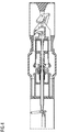
- the FIG. 1 shows a switching arrangement in section.
- the switching arrangement has an encapsulating housing 1.
- the encapsulating housing 1 is substantially tubular and aligned coaxially to a longitudinal axis 2.
- the encapsulating housing 1 is made, for example, of electrically conductive material and surrounds an interrupter unit arranged in the interior.
- the encapsulating housing 1 preferably carries ground potential.
- the interrupter unit has a first contact set 3 and a second contact set 4.
- the interrupter unit is supported relative to the encapsulating housing 1 by means of electrically insulating post insulators.
- exemplary is a post insulator 5 in the FIG. 1 shown.
- the encapsulating housing 1 has on its shell-side circumference a plurality of flange stubs 6, 7.
- the flange stubs 6, 7 serve to introduce phase conductors into the interior of the encapsulating housing 1 in order to electrically contact the interrupter unit located there and to integrate them into a current path to be interrupted.
- the phase conductors pass through the jacket-side flange connection 6, 7 electrically isolated and fluid-tight.
- disc-shaped insulators are arranged around the phase conductors for fluid-tight closing of the encapsulating housing 1, which isolate the flange stubs 6, 7 in a fluid-tight manner. Furthermore, frontal openings of the encapsulating housing 1 are closed by corresponding flange cover.
- the interior of the encapsulating housing 1 is filled with an electrically insulating fluid, for example sulfur hexafluoride gas or another electrically insulating gas.
- the electrically insulating fluid flows around and flushes through the interrupter unit of the switching arrangement, which is arranged in the interior of the encapsulating housing 1.
- the interrupter unit is aligned with its longitudinal axis in alignment with the longitudinal axis 2 of the encapsulating housing.
- the interrupter unit has a first support body 8 and a second support body 9.
- the first support body 8 serves to position the first contact set 3.
- the second support body 9 serves to position the second contact set 4.
- the two support bodies 8, 9 are in this case formed differently from each other. However, it can also be provided that similarly shaped support body 8, 9 are used.
- the two supporting bodies 8, 9 are in each case formed as hollow bodies which are of substantially rotationally symmetrical design, wherein the two supporting bodies 8, 9 have an electrically conductive material (eg a metal) and with the phase conductors which pass through the flange stubs 6, 7 are conducted into the interior of the encapsulating housing 1, are electrically conductively contacted.
- the support members 8, 9 thus form part of a current path which is to be interrupted by the switching arrangement.
- the two support bodies 8, 9 are aligned with their axes of rotation coaxially to the longitudinal axis 2 and spaced from each other, wherein mutually facing end faces of the two support body 8, 9 are connected to each other with an angular locking by an electrically insulating Beabstandungsêt.
- the spacer body 10 is in the FIG. 1 represented symbolically.
- the electrically insulating Beabstandungsisson 10 has a plurality of circumferentially distributed around the longitudinal axis 2 arranged rods which connect the two support members 8, 9 in a rigid manner with each other like a cage.
- the switching chamber 11 of the switching arrangement is arranged.
- the switching chamber 11 projects an insulating nozzle 12 into it.
- the insulating nozzle arrangement 12 has a main nozzle 12a and an auxiliary nozzle 12b.
- the main nozzle 12a and the auxiliary nozzle 12b define together a nozzle channel which is aligned coaxially with the longitudinal axis 2.
- Main nozzle and auxiliary nozzle 12a, 12b are each constructed rotationally symmetrical, wherein the auxiliary nozzle 12b projects into the main nozzle 12a.
- an annular channel is formed, which opens from the radial direction into the nozzle channel.
- the annular channel connects the nozzle channel with a heating volume 13.
- the Isolierdüsenan extract 12 with its main nozzle 12a and its auxiliary nozzle 12b is connected at an angle with an axially displaceable in the first support body 8 positioned first rated current contact piece 14.
- An axial movement of the first rated current contact piece 14 in the direction of the longitudinal axis 2 is transmitted to the insulating nozzle assembly 12 so that it is similar to the first rated current contact piece 14 is moved.
- the first rated current contact piece 14 is electrically conductively contacted to the first support body 8 by means of a sliding contact.
- the first contact set 3 has a first arcing contact piece 15.
- the first arcing contact piece 15 is tubular and aligned coaxially with the longitudinal axis 2. At its end facing the nozzle channel of the insulating nozzle arrangement 12, the first arcing contact piece 15 has a contact socket for forming a contacting region of the first arcing contact piece 15.
- the contact bushing surrounds a mouth opening of a channel formed on the inner shell side on the tubular first arcing contact piece 15.
- the first arcing contact piece 15 is electrically conductively connected to the first support body 8 via a sliding contact arrangement.
- the first arcing contact piece 15 and the first rated current contact piece 14 always have the electrical potential of the first support body 8.
- a drive rod 16 is coupled.
- the drive rod 16 is equipped with a transverse bolt, which is guided in a slot of a drive element 25 of the first rated current contact piece 14 or the Isolierdüsenan ever 12.
- the drive rod 16 passes through a wall of the encapsulating 1 fluid-tight. Thus, it is possible to transmit a movement generated outside of the encapsulating housing 1 to the first contact set 3.
- the mouth opening of the channel of the first arcing contact piece 15 is arranged at a distance from an end-side mouth opening of the nozzle channel of the insulating nozzle arrangement 12.
- the mouth opening of the nozzle channel is located in a recess of the insulating nozzle assembly 12, in which the first arcing contact piece 15 protrudes.
- the first arcing contact piece 15 protrudes into the recess of the insulating nozzle arrangement independently of the switching position of the switching device.
- a movement of the first rated current contact piece 14 is coupled via a reduction gear 17 also to the first arcing contact piece 14 (see. Fig. 7 ).
- the reduction gear 17 has a lever arrangement, which causes a movement of the first rated current contact piece 14 / the Isolierdüsenan Aunt 12 and a speed increased movement of the first arcing contact piece 15 at a power-up.
- a switch-off is a Movement of the first rated current contact piece 14 / the insulating nozzle assembly 12 and a speed increased movement of the first arcing contact piece 15 executed.
- a movement of the first rated current contact piece 14 is also transmitted to the insulating nozzle assembly 12 due to the rigid coupling of the insulating nozzle assembly 12 on the first rated current contact piece 14.
- the insulating nozzle arrangement 12 is struck on the inner side of the first rated current contact piece 14 and surrounds at least the contacting region with the contact socket of the first arcing contact piece 15 on the outer jacket side. Furthermore, located between the orifices of the nozzle channel and the channel of the first arcing contact piece 15 gap variable dimension is encompassed by the Isolierdüsenan angel 12.
- crank arm 20 Fixedly mounted on the second supporting body 9.
- the crank arm 20 is a rotary lever and converts an axial movement of the insulating nozzle assembly 12 into a rotational movement.
- a slide passage 21 is arranged, in which a sensing element is guided, which is connected to a linearly displaceable second rated current contact piece 22.
- the second rated current contact piece 22 is axially displaceably mounted on the second support body 9 and electrically conductively connected to the second support body 9.
- the second rated current contact piece 22 is designed as a hollow cylinder, wherein coaxial with the second rated current contact piece 22, a second arcing contact piece 23 is arranged encompassed by the second rated current contact piece 22.
- the second arcing contact piece 23 is displaceably mounted on the second rated current contact piece 22.
- a supplementary movement can be coupled to the second arcing contact piece 23, so that the movement profile of the moving one second rated current contact piece 22 forms the basis for a movement of the second arcing contact piece 23, wherein the movement profiles of the first rated current contact piece 22 and the second arcing contact piece 23 complement, so that the second arcing contact piece 23 with respect to the second support body 9 is movable at a greater speed than the second rated current contact piece 22nd
- a relative movement of the first arcing contact piece 15 to the insulating nozzle arrangement 12 is ensured.
- the second rated current contact piece 23 still remains at rest, since the sliding gear 21 of the crank arm 20 due to its lying in this area concentric with the fulcrum path no movement on the first rated current contact piece 14 couples. Consequently, the second arcing contact piece 23, which is supported on the second rated current contact piece 23, also remains at rest.
- an opposite movement is transmitted to the second arcing contact piece 23 in the following.
- both the first rated current contact piece 14 and the second rated current contact piece 22 and the first arcing contact piece 15 and the second arcing contact piece 23 are removed from each other.
- a removal of the first arcing contact piece 15 from the region of the switching chamber 11 is faster than a distance of the first rated current contact piece 14 from the switching chamber 11.
- the first arcing contact piece 15 is moved into the screen area of the first rated current contact piece 14, resulting in a distance of the first arcing contact piece 15 the opening of the nozzle channel of the insulating nozzle arrangement 12 facing the first arcing contact piece 15 increases.
- a switched after the contact separation of the two arcing contact pieces 15, 23 Ausschaltlichtbogen (change from the Fig. 4 to the Fig. 5 ) burns between the two arcing contact pieces 15, 23 and is guided within the nozzle channel of the insulating nozzle assembly 12.
- the nozzle channel of the switching arc expands so-called switching gas, which can escape via the frontal mouth opening of the nozzle channel, which faces the first arcing contact piece 15.
- the switching gas emerging from the nozzle channel of the insulating nozzle arrangement 12 is radiated into the mouth opening of the channel of the first arcing contact piece 15.
- the first arcing contact piece 15 discharges the switching gas from the switching chamber.
- the radial annular channel formed between the main nozzle 12a and the auxiliary nozzle 12b is used to derive switching gas from the area of the burning switching arc from the nozzle channel of the insulating nozzle arrangement 12. This switching gas is introduced into the heating volume 13. Due to the thermal energy input, the expanding switching gas is compressed within the heating volume 13.
- the reduction gear 17 is shown in detail.
- the drive rod 16 is connected via a transverse bolt to a drive element 25 of the first rated current contact piece 14 or the Isolierdüsenan ever 12.
- the cross pin engages in a slot of the drive element 25 a.
- the reduction gear 17 is equipped with a one-armed lever 26.
- the one-armed lever 26 is struck stationary on the first support body 8.
- the one-armed lever 26 is connected at its free end with the transverse bolt in the slot of the drive element 25.
- a coupling with the linearly displaceable for transmitting a movement drive rod 16 is given via the one-armed lever 26.
- the one-armed lever 26 is pivoted upon movement of the drive rod 16. To compensate for an overstroke of the one-armed lever 26, this slides through the slot of the drive element 25.
- the elastically deflectable drive rod 16 is moved over the cross bolt from its coaxial position to the longitudinal axis 2 to compensate for the overstroke of the one-armed lever 26.
- the one-armed lever 26 is further provided with a drive pin 27, wherein the distance of the drive pin 27 to the pivot point of the one-armed lever 26 is greater than the distance of the transverse pin to the pivot point of the one-arm lever 26.
- the drive pin 27 upon pivoting of the one-armed lever 26th the drive pin 27 a greater way back than the cross pin, so that a relation to the movement of the transverse pin deviating motion on the drive pin 27 can be tapped.
- a Lasehe 28 struck which is connected to the linearly displaceable first arcing contact piece 15.
- the tab 28 is connected via a linearly displaceable push element which is guided in the interior of the tubular drive element 25.
- the tab 28 is discharged through a jacket-side opening in the drive element 25 cranked and coupled to a slot on the drive pin 27. In this case, the slot is directed so that an overstroke of the located on the one-armed lever 26 drive pin 27 can be compensated.
- FIG. 8 shows an alternative transmission gear.
- a two-armed lever 29 is rotatably mounted.
- the drive rod 16 is connected to the drive element 25, so that movements of the drive rod 16 are transmitted directly to the drive element 25 and consequently also to the first rated current contact piece 14 and the Isolierdüsenan accent 12.
- the two-armed lever 29 is connected with its one lever arm with a tab 28 which is guided linearly displaceable in the drive element 25 and transmits a movement to the first arcing contact piece 15.
- a sliding gate 30 is fixedly positioned on the first supporting body 8. The slide gate 30 is scanned by the other lever arm of the two-armed lever 29, while the pivot point of the two-armed lever 29 is moved together with the drive element 25. Due to the shape of the link 30, insertion or suspension of transmission of movement of the tab 28 / the first arcing contact 15 can be easily adjusted.
- the end regions of the sliding gear 30 arranged parallel to the axis of movement of the drive element 25.
Landscapes
- Circuit Breakers (AREA)
- Arc-Extinguishing Devices That Are Switches (AREA)
- Driving Mechanisms And Operating Circuits Of Arc-Extinguishing High-Tension Switches (AREA)
Description
- Die Erfindung betrifft eine Schaltanordnung mit einem ersten Kontaktsatz und einem relativ zum ersten Kontaktsatz bewegbaren zweiten Kontaktsatz, sowie mit einer am ersten Kontaktsatz abgestützten Isolierdüsenanordnung, wobei der erste Kontaktsatz ein erstes Lichtbogenkontaktstück aufweist.
- Die aus dem US-Patent
US 5,578,806 bekannte Schaltanordnung weist einen ersten sowie einen zweiten Kontaktsatz auf, wobei am ersten Kontaktsatz eine Isolierdüsenanordnung abgestützt ist. Der erste Kontaktsatz ist mit einem Lichtbogenkontaktstück ausgestattet, welches der Führung eines Schaltlichtbogens dient. Die Isolierdüsenanordnung dient einem Lenken und Leiten eines brennenden Schaltlichtbogens sowie eines von dem Schaltlichtbogen expandierten Gases. Ein Schaltlichtbogen übt eine thermische Beeinflussung auf seine Umgebung aus. Entsprechend sind das erste Lichtbogenkontaktstück sowie die Isolierdüsenanordnung derart auszugestalten, dass sie eine ausreichend Widerstandskraft aufweisen, um Schaltlichtbögen wiederholt lenken, leiten und führen zu können. Trotz einer geeigneten Auslegung des ersten Lichtbogenkontaktstückes und der Isolierdüsenanordnungen kommt es zu Abbranderscheinungen. Folglich sind bekannte Schaltanordnungen regelmäßig zu revidieren. Weiterhin treten im Bereich der Isolierdüsenanordnung Überhöhungen des elektrischen Feldes auf, die zu zusätzlichen Belastungen führen.KR 10-2007-0008041 - Somit ergibt sich als Aufgabe, eine Schaltanordnung anzugeben, deren Baugruppen in geringerem Maße beansprucht werden.
- Erfindungsgemäß wird die Aufgabe durch eine Schaltanordnung gemäß des Anspruchs 1 und durch ein Betätigungsverfahren gemäß des Anspruchs 9 gelöst. Weitere Ausgestaltungen ergeben sich aus den Unteransprüchen.
- Eine Schaltanordnung mit einem ersten Kontaktsatz sowie einem zweiten Kontaktsatz ist dazu eingerichtet, einen Strompfad zu unterbrechen. Dazu sind die beiden Kontaktsätze relativ zueinander bewegbar, so dass im eingeschalteten Zustand eine galvanische Kontaktierung der beiden Kontaktsätze vorliegt, wohingegen im ausgeschalteten Zustand eine elektrisch isolierte Beabstandung der beiden Kontaktsätze vorliegt. Während eines Überführens der Schaltanordnung von ihrem Einschaltzustand in ihren Ausschaltzustand kann es zu einem Zünden eines sogenannten Schaltlichtbogens zwischen den beiden Kontaktsätzen kommen. Insbesondere der erste Kontaktsatz kann ein erstes Lichtbogenkontaktstück aufweisen, welches derart ausgelegt ist, dass es eine erhöhte Widerstandsfähigkeit gegen die Wirkungen eines Schaltlichtbogens aufweist. Insbesondere dient das erste Lichtbogenkontaktstück der Führung eines Fußpunktes des Schaltlichtbogens, so dass das erste Lichtbogenkontaktstück zum einen zur Führung eines elektrischen Stromes in der Lage sein muss und zum anderen eine ausreichende Abbrandfestigkeit aufweisen muss.
- Das erste Lichtbogenkontaktstück interagiert während eines Schaltvorganges mit der Isolierdüsenanordnung, wobei die Isolierdüsenanordnung einen Schaltlichtbogen, welcher am ersten Lichtbogenkontaktstück geführt ist, bevorzugt umgreift und in einem Düsenkanal leitet. Somit ist die Möglichkeit gegeben, ein beliebiges Ausbauchen des Schaltlichtbogens zu begrenzen. Insbesondere kann zwischen den beiden Kontaktsätzen eine Schaltkammer angeordnet sein, in welcher das Brennen eines Schaltlichtbogens bevorzugt stattfinden sollte. Die Isolierdüsenanordnung kann dabei in eine derartige Schaltkammer hineinragen. Bevorzugt kann die Isolierdüsenanordnung auch Teile der Schaltkammer begrenzen bzw. die Schaltkammer in unterschiedliche Zonen unterteilen. Beispielsweise kann die Isolierdüse die Schaltkammer durchsetzen und über einen Düsenkanal eine Kommunikation eines Fluids zwischen dem ersten Kontaktsatz und dem zweiten Kontaktsatz ermöglichen. Beispielsweise kann die Schaltanordnung, insbesondere die Schaltkammer sowie die Kontaktsätze von einem elektrisch isolierenden Fluid durchflutet sein, welches zum einen einem elektrischen Isolieren von unterschiedliche elektrische Potentiale führenden Elementen dient, zum anderen aber auch einem Kühlen bzw. Beblasen und schließlich einem Löschen eines Schaltlichtbogens dienen kann. Beispielsweise kann es sich bei dem elektrisch isolierenden Fluid um eine Isolieröl oder auch um ein Isoliergas, beispielsweise Schwefelhexafluorid, Stickstoff, Kohlendioxid oder Gemische mit diesen Gasen handeln. Eine Bewegung des ersten Lichtbogenkontaktstückes relativ zur Isolierdüsenanordnung ermöglicht es, die Isolationsfestigkeit im Bereich der Schaltkammer positiv zu beeinflussen. Beispielsweise kann durch eine Bewegung des Lichtbogenkontaktstückes relativ zur Isolierstoffdüse im ausgeschalteten Zustand eine vergrößerte fluidbefüllbare Lücke zwischen der Isolierstoffdüsenanordnung sowie dem ersten Lichtbogenkontaktstück angeordnet sein. Innerhalb dieses Bereiches ist es möglich, elektrisch isolierendes Fluid anzusammeln, so dass die dielektrische Festigkeit am ersten Lichtbogenkontaktstück erhöht wird, indem dort ein vergrößertes Volumen von elektrisch isolierendem Fluid eingelagert wird. Weiter ist von Vorteil, wenn dass erste Lichtbogenkontaktstück, beispielsweise während der Führung und Lenkung eines Lichtbogens besonders nah an der Isolierdüsenanordnung positioniert ist, so dass ein Ausbrechen des Schaltlichtbogens im Zusammenspiel mit der Isolierdüsenanordnung verhindert wird. So ist durch eine Annäherung des ersten Lichtbogenkontaktstückes an die Isolierdüsenanordnung die Weglänge, welche einem brennenden Schaltlichtbogen zur Verfügung steht, reduziert und ein Ausbrechen des Schaltlichtbogens aus der Schaltkammer, insbesondere aus einem Düsenkanal der Isolierdüsenanordnung, ist erschwert. Die Isolierdüsenanordnung kann beispielsweise eine Hauptdüse sowie eine Hilfsdüse aufweisen, die gemeinsam einen Düsenkanal begrenzen. Dabei können die Hauptdüse und die Isolierdüse beispielsweise einander teilweise überlappen, so dass zwischen Hauptdüse und Hilfsdüse ein Ringspalt gebildet ist, welcher aus einer radialen Richtung in dem Düsenkanal mündet. Somit ist hier die Möglichkeit gegeben, eine radiale Mündungsöffnungen in dem Düsenkanal einzubringen und aus dieser radialen Mündungsöffnung beispielsweise heiße Schaltgase auszuleiten. So ist beispielsweise eine Druckentlastung im Düsenkanal der Isolierdüsenanordnung ermöglicht. Weiter kann die radiale Mündungsöffnung im Düsenkanal dazu genutzt werden, um erhitztes und im Volumen vergrößertes Isoliergas (Schaltgas) in ein sogenanntes Heizvolumen zu verbringen, zwischenzuspeichern und dieses gegebenenfalls später aus dem Heizvolumen zu entlassen, um eine rasche Verfestigung der Schaltstrecke zwischen den Kontaktsätzen zu befördern. Ein Heizvolumen sollte ortsfest am ersten Kontaktsatz angeordnet sein. Entsprechend ergibt sich auch eine ortsfeste Lage des Heizvolumens zu der Isolierdüsenanordnung. Das Heizvolumen kann beispielsweise von dem ersten Lichtbogenkontaktstück durchsetzt sein. Bevorzugt kann das Heizvolumen eine rotationssymmetrische Form aufweisen, welche zentrisch vom ersten Lichtbogenkontaktstück durchsetzt ist. Das Heizvolumen kann außen mantelseitig von einem ersten Nennkontaktstück umgriffen sein. Das erste Lichtbogenkontaktstück kann relativ zum Heizvolumen bewegbar sein.
- Insbesondere kann vorgesehen sein, dass die Isolierdüsenanordnung eine im Wesentlichen rotationssymmetrische Struktur aufweist, wobei der von der Isolierdüsenanordnung begrenzte Düsenkanal koaxial zur Rotationsachse ausgerichtet ist. Entsprechend sollten sowohl die Hauptdüse als auch die Hilfsdüse jeweils rotationssymmetrisch ausgebildet sein, wobei Haupt- und Hilfsdüse einander in radialer Richtung durch Ineinanderstecken überlappen, so dass beispielsweise im Düsenkanal zwischen Haupt- und Hilfsdüse eine Mündungsöffnung geschaffen ist, die in radialer Richtung im Düsenkanal liegt.
- Die Isolierdüsenanordnung ist winkelstarr mit dem ersten Kontaktsatz verbunden sein. Die Isolierdüsenanordnung kann von dem ersten Kontaktsatz zumindest teilweise, insbesondere vollständig getragen sein. Der erste Kontaktsatz kann mehrteilig ausgeführt sein, so dass das erste Lichtbogenkontaktstück relativ zur Isolierdüsenanordnung bewegbar ist. Weiter kann vorgesehen sein, dass die Isolierdüsenanordnung am zweiten Kontaktsatz gleitend anliegt. Dazu kann die Isolierdüsenanordnung die Schaltkammer durchsetzen, so dass die erste und die zweite Kontaktseite voneinander elektrisch isoliert sind und eine mechanische Brücke zwischen den in Trennstellung befindlichen Kontaktseiten durch die Isolierdüsenanordnung gebildet ist.
- Das erste Lichtbogenkontaktstück kann zumindest teilweise von der Isolierdüsenanordnung umgriffen sein. Beispielsweise kann die Isolierdüsenanordnung eine Ausnehmung aufweisen, in welche das erste Lichtbogenkontaktstück hineinragt. Das erste Lichtbogenkontaktstück kann beispielsweise formkomplementär in die Ausnehmung hineinragen. Weiterhin kann vorgesehen sein, dass durch eine Relativbewegung zwischen Isolierdüsenanordnung und erstem Lichtbogenkontaktstück die Eintauchtiefe des ersten Lichtbogenkontaktstückes in die Ausnehmung der Isolierdüsenanordnung variiert wird. Das erste Lichtbogenkontaktstück kann beispielsweise in den Düsenkanal hineinragen, insbesondere in einen querschnittsvergrößerten Abschnitt des Düsenkanals. Weiter kann der Düsenkanal in einer Ausnehmung der Düsenanordnung münden, wobei das erste Lichtbogenkontaktstück insbesondere formkomplementär in die Ausnehmung hineinragt. Im Zuge einer Relativbewegung kann der Abstand zwischen dem in die Ausnehmung ragenden Lichtbogenkontaktstück und der Mündungsöffnung des Düsenkanals in der Ausnehmung variieren.
- Weiterhin kann vorteilhaft vorgesehen sein, dass die Isolierdüsenanordnung einen Düsenkanal begrenzt, der eine Mündungsöffnung aufweist, welche einer Mündungsöffnung eines Kanals des ersten Lichtbogenkontaktstückes gegenüberliegt.
- Der Düsenkanal der Isolierdüsenanordnung erstreckt sich bevorzugt bei einer rotationssymmetrischen Isolierdüsenanordnung koaxial zur Rotationsachse der Isolierdüsenanordnung. Bevorzugt sollte der Düsenkanal zentrisch in der Isolierdüsenanordnung geführt sein. Der Düsenkanal weist jeweils stirnseitig Mündungsöffnungen auf, wobei insbesondere eine stirnseitige Mündungsöffnung des Düsenkanals einer Mündungsöffnung eines Kanals des ersten Lichtbogenkontaktstückes gegenüberliegend angeordnet ist. Somit ist es beispielsweise möglich, aus dem Düsenkanal austretende Medien in den Kanal des ersten Lichtbogenkontaktstückes eintreten zu lassen. Somit ist es beispielsweise möglich, über den aus einem bevorzugt abbrandfesten Material gebildeten Kontaktierungsbereich des ersten Lichtbogenkontaktstückes erhitzte Schaltgase in das erste Lichtbogenkontaktstück einzustrahlen und das erste Lichtbogenkontaktstück zu nutzen, um heiße Schaltgase aus der Schaltkammer herauszuleiten. Beispielsweise kann das erste Lichtbogenkontaktstück in Form eines sogenannten Rohrkontaktstückes ausgeformt sein, so dass ein gestreckter Kanal am ersten Lichtbogenkontaktstück gebildet ist, welcher bevorzugt fluchtend zum Düsenkanal der Isolierdüsenanordnung ausgerichtet ist. Insbesondere bei einer buchsenförmigen Ausgestaltung des Kontaktierungsbereiches des ersten Lichtbogenkontaktstückes kann der buchsenförmige Kontaktierungsbereich als Mündungsöffnung des Kanals dienen. Der buchsenförmige Kontaktierungsbereich kann außenmantelseitig von der Isolierdüsenanordnung umgriffen sein, so dass ein verlustarmer Übertritt von den aus dem Düsenkanal austretenden Medien in den Kanal des ersten Lichtbogenkontaktstückes gegeben ist. Der Düsenkanal kann beispielsweise in einer Ausnehmung der Düsenanordnung münden, wobei das erste Lichtbogenkontaktstück formkomplementär in die Ausnehmung hineinragt. Die Ausnehmung kann bezüglich des Querschnittes der Mündungsöffnung des Düsenkanals radial erweitert sein. Eine um die Mündungsöffnung umlaufende Schulter bietet so Raum zur Aufnahme einer die Mündungsöffnung des Kanals des ersten Lichtbogenkontaktstückes umschließenden Wandung. Eine Bewegung des ersten Lichtbogenkontaktstückes relativ zur Isolierdüsenanordnung kann dabei bevorzugt derart vorgesehen sein, dass die einander zugewandten Mündungsöffnungen des Düsenkanals bzw. des Kanals des ersten Lichtbogenkontaktstückes sich einander nähern oder sich voneinander entfernen. Die Mündungsöffnungen sollten dabei im Wesentlichen quer zu einer Bewegungsachse der Relativbewegung zwischen erstem Lichtbogenkontaktstück und Isolierdüsenanordnung liegen. Bevorzugt sollten die Querschnitte der Mündungsöffnungen gleichartig fluchtend angeordnet sein. Entsprechend ist die Möglichkeit gegeben, zu Beginn eines Ausschaltvorganges den Abstand der Mündungsöffnungen möglichst gering zu halten. Die Mündungsöffnungen können dabei einander berühren, so dass ein nahezu spaltfreier Übergang von dem Düsenkanal zu dem Kanal des ersten Lichtbogenkontaktstückes gegeben ist. Es kann jedoch auch vorgesehen sein, dass zwischen den Mündungsöffnungen des Düsenkanals sowie des Kanals des ersten Lichtbogenkontaktstückes auch bei minimaler Beabstandung weiterhin ein Spalt verbleibt, welcher von elektrisch isolierendem Fluid befüllt ist. Diese Beabstandung ist vorteilhaft, um die Isolationsfestigkeit aufrecht zu erhalten. So ist beispielsweise die Möglichkeit gegeben, dass selbst bei einem Abbrand von die Mündungsöffnungen umgebenden Bereichen an der Isolierdüsenanordnung bzw. an dem ersten Lichtbogenkontaktstück, ein elektrisch isolierter Bereich gebildet ist, der aufgrund der fluiden Ausgestaltung auch selbstreparierend/selbstanpassend wirkt. Im Vergleich zu einem Aufeinanderstoßen, undefiniert abgebrannter Oberflächen, ist so eine dielektrisch stabile Konstruktion gegeben. Es kann dabei insbesondere vorgesehen sein, dass im eingeschalteten Zustand die minimale Beabstandung der Mündungsöffnungen von Isolierdüsenkanal und dem Kanal im ersten Lichtbogenkontaktstück vorliegt. Der zwischen den Mündungsöffnungen verbleibende Spalt kann außenmantelseitig von der Isolierdüsenanordnung umgriffen sein. Es kann vorgesehen sein, dass unabhängig von der Breite des Spaltes dieser stets von der Isolierdüsenanordnung umgriffen ist. So wird einem radialen Verflüchtigen von aus dem Düsenkanal austretendem Schaltgas entgegengewirkt. Ein Umgreifen des ersten Lichtbogenkontaktstückes kann beispielsweise durch ein Hineinragen des ersten Lichtbogenkontaktstückes in eine Ausnehmung der Isolierdüsenanordnung erzielt werden. Unabhängig von der Dimension des Spaltes zwischen den einander zugewandten Mündungsöffnungen sollte das erste Lichtbogenkontaktstück dauerhaft in der Ausnehmung verbleiben. Korrespondierend zur Änderung des Spaltes kann die Eintauchtiefe des ersten Lichtbogenkontaktstückes in der Ausnehmung variieren.
- Eine Vergrößerung der Beabstandung der Mündungsöffnungen sollte vor einem Zeitpunkt erfolgen, in welchem ein Erlöschen eines Schaltlichtbogens bereits erfolgt ist. Insbesondere sollte das erste Lichtbogenkontaktstück mit einem zweiten Lichtbogenkontaktstück des zweiten Kontaktsatzes zusammenwirken. Während der Dauer der Kontaktierung der beiden Lichtbogenkontaktstücke sind die einander zugewandten Mündungsöffnungen des Isolierdüsenkanals bzw. des Kanals des ersten Lichtbogenkontaktstückes unter Freilassung eines kleinen Spaltes einander angenähert. Mit/nach einer galvanischen Trennung der Lichtbogenkontaktstücke und einem zu diesem Zeitpunkt gegebenenfalls schon brennenden Schaltlichtbogens erfolgt bevorzugt eine Vergrößerung der Beabstandung der Mündungsöffnungen des Düsenkanals und des Kanals des ersten Lichtbogenkontaktstückes. Mit einer zusätzlichen Beabstandung bzw. zusätzlichen Bewegung des ersten Lichtbogenkontaktstückes relativ zur Isolierdüsenanordnung erfolgt eine zusätzliche Vergrößerung der Isolierstrecke zwischen den beiden Kontaktsätzen. Gleichzeitig wird zwischen der Isolierdüsenanordnung und dem ersten Lichtbogenkontaktstück im sich vergrößernden Spalt zwischen den einander zugewandten Mündungsöffnungen ein Polster aus elektrisch isolierendem Fluid aufgebaut, welches zusätzlich kühlend auf den Lichtbogen wirkt. Weiterhin ist vorteilhaft, wenn das erste Lichtbogenkontaktstück in den Feldschatten eines Schirmungselementes eingefahren wird. Ein derartiges Schirmungselement kann beispielsweise eine separate Feldsteuerelektrode sein. Es kann jedoch auch vorgesehen sein, dass dem ersten Lichtbogenkontaktstück ein erstes Nennstromkontaktstück zugeordnet ist, welches das erste Lichtbogenkontaktstück zumindest teilweise umgreift. Mit einer Relativbewegung zwischen erstem Lichtbogenkontaktstück und Isolierdüsenanordnung kann das erste Lichtbogenkontaktstück gezielt in den Schirmbereich des Schirmungselementes eingefahren werden. Somit wird ein Rückzünden des Lichtbogens nach erfolgter Löschung erschwert, da im Feldschatten nunmehr Feldstärkeüberhöhungen an dem ersten Lichtbogenkontaktstück durch die elektrische Schirmwirkung abgebaut sind.
- Vorteilhafterweise kann weiter vorgesehen sein, dass der Düsenkanal einem Leiten eines fluiden Mediums dient und aus der Mündungsöffnung des Düsenkanals austretendes fluides Medium in den Kanal einströmt.
- Ein zwischen den Kontaktsätzen brennender Schaltlichtbogen erhitzt und expandiert innerhalb der Schaltkammer zwischen den Kontaktsätzen befindliches elektrisch isolierendes Fluid. Aufgrund der thermischen Wirkung wird das elektrisch isolierende Fluid in seiner Temperatur erhöht und dabei einer Volumenvergrößerung unterworfen. Um einem Bersten der Schaltanordnung entgegenzuwirken, ist es vorteilhaft, dieses sogenannte Schaltgas (fluides Medium) aus der Schaltstrecke zwischen den Kontaktsätzen herauszuführen und einer Entspannung zu unterziehen. Dabei ist es vorteilhaft, das Schaltgas abzuleiten und in unkritische Bereiche der Schaltanordnung zu führen, in welcher das Schaltgas beispielsweise mit kühlerem Gas durchmischt und entspannt werden kann. Ein Übertreten von einem fluiden Medium aus dem Düsenkanal in den Kanal des ersten Lichtbogenkontaktstückes nutzt die Formgebung des ersten Kontaktsatzes aus, um neben einem elektrischen Leiten des Stromes auch eine Fluidleitung und Fluidführung vorzunehmen. Durch eine Bewegung des ersten Lichtbogenkontaktstückes relativ zur Isolierdüsenanordnung ist auch der Abstand zwischen den Mündungsöffnungen des Düsenkanals sowie des Kanals des ersten Lichtbogenkontaktstückes variabel ausgestaltbar. Beispielsweise kann bei einem Auftreten von hohen Schaltgasmengen (z. B. Beginn eines Ausschaltvorganges) eine Reduzierung der Beabstandung der Mündungsöffnungen vorgesehen sein, wohingegen mit sich reduzierenden Schaltgasmengen (z. B. Ende eines Ausschaltvorganges) eine vergrößerte Beabstandung der Mündungsöffnungen vorgesehen sein kann. Weiterhin kann eine rasche dielektrische Verfestigung der Schaltstrecke zwischen den Kontaktsätzen durch eine dielektrische Schirmung des Kontaktierungsbereiches des ersten Lichtbogenkontaktstückes unterstützt werden, so dass einem unterwünschten Rückzünden eines Schaltlichtbogens während eines Ausschaltvorganges entgegengewirkt wird.
- Eine weitere vorteilhafte Ausgestaltung kann vorsehen, dass der Kanal zumindest abschnittsweise von einer Kontaktbuchse des ersten Lichtbogenkontaktstückes umgriffen ist.
- Das erste Lichtbogenkontaktstück kann beispielsweise eine Kontaktbuchse aufweisen, in welche ein gegengleich geformtes zweites Lichtbogenkontaktstück des zweiten Kontaktsatzes einfahrbar ist. So ist in einfacher Art und Weise eine galvanische Kontaktierung zweier Lichtbogenkontaktstücke ermöglicht. Zum anderen kann die Kontaktbuchse auch genutzt werden, eine Mündungsöffnung für einen Kanal in dem ersten Lichtbogenkontaktstück bereitzustellen. Über die Kontaktbuchse kann somit ein aus dem Düsenkanal austretendes fluides Medium in den Kanal des ersten Lichtbogenkontaktstückes eintreten. Die Kontaktbuchse kann von der Isolierdüsenanordnung umgeben sein, um einen möglichst verlustarmen Übertritt von Schaltgas aus dem Düsenkanal in den Kanal des ersten Lichtbogenkontaktstückes sicherzustellen.
- Eine weitere vorteilhafte Ausgestaltung kann vorsehen, dass der erste Kontaktsatz ein erstes Nennstromkontaktstück aufweist, welches die Isolierdüsenanordnung zumindest teilweise trägt.
- Die Ausstattung des ersten Kontaktsatzes mit einem ersten Nennstromkontaktstück ermöglicht es, am ersten Kontaktsatz das erste Lichtbogenkontaktstück zum Führen eines Lichtbogens zu nutzen, wohingegen das erste Nennstromkontaktstück dem Führen eines Nennstromes dient. Entsprechend kann das erste Nennstromkontaktstück hinsichtlich seiner elektrischen Impedanz optimiert werden, wohingegen das erste Lichtbogenkontaktstück hinsichtlich seiner Widerstandskraft gegenüber den Einwirkungen eines Schaltlichtbogens optimiert werden kann. Das erste Lichtbogenkontaktstück sollte zum ersten Nennstromkontaktstück relativ bewegbar sein. Es kann beispielsweise vorgesehen sein, dass das erste Lichtbogenkontaktstück und das erste Nennstromkontaktstück dauerhaft das gleiche Potential führen, wobei bei einem Ausschaltvorgang zunächst eine Aufhebung einer galvanischen Verbindung des ersten Nennstromkontaktstückes mit beispielsweise einem zweiten Nennstromkontaktstück des zweiten Kontaktsatzes erfolgt, wobei darauf folgend eine galvanische Trennung des ersten Lichtbogenkontaktstückes von gegebenenfalls einem zweiten Lichtbogenkontaktstück des zweiten Kontaktsatzes erfolgt. Entsprechend kann ein zu unterbrechender elektrischer Strom von den Nennstromkontaktstücken auf die Lichtbogenkontaktstücke kommutieren und dort nach erfolgter galvanischer Trennung in Form eines Schaltlichtbogens fließen. Dieser Schaltlichtbogen ist während einer Schalthandlung zu unterbrechen, so dass schlussendlich ein elektrischer Strom ausgeschaltet werden kann. Bei einem Einschaltvorgang ist umgekehrt zunächst die Kontaktierung der Lichtbogenkontaktstücke und darauf folgend eine Kontaktierung der Nennstromkontaktstücke vorgesehen. So sind auch während eines Einschaltvorganges auftretende Vorüberschläge bevorzugt an den Lichtbogenkontaktstücken geführt.
- Das erste Nennstromkontaktstück kann die Isolierdüsenanordnung zumindest teilweise tragen. Zwischen dem ersten Nennstromkontaktstück und der Isolierdüsenanordnung ist ein winkelstarrer Verbund ausgebildet, so dass Bewegungen des ersten Nennstromkontaktstückes auch auf die Isolierdüsenanordnung (und umgekehrt) übertragen werden. Bevorzugt sollte das erste Nennstromkontaktstück nach Art eines Rohrkontaktes ausgebildet werden, wobei eine Befestigung der Isolierdüsenanordnung bevorzugt innenmantelseitig, d. h., in einem dielektrisch geschirmten Bereich eines rohrförmig ausgebildeten ersten Nennstromkontaktstückes, vorgenommen werden sollte. Bevorzugt sollte das erste Nennstromkontaktstück dazu als rotationssymmetrischer Körper ausgebildet sein, dessen Rotationsachse koaxial zu einer im Wesentlichen rotationssymmetrischen Isolierdüsenanordnung angeordnet ist. Bevorzugt sollte, umgriffen von dem ersten Nennstromkontaktstück, das erste Lichtbogenkontaktstück rohrförmig ausgestaltet sein und koaxial zur Rotationsachse der Isolierdüsenanordnung und des ersten Nennstromkontaktstück liegen. Bevorzugt sollte im Bereich einer Kontaktbuchse des ersten Lichtbogenkontaktstückes das erste Lichtbogenkontaktstück außenmantelseitig von der Isolierdüsenanordnung umgeben sein, wobei die Isolierdüsenanordnung in diesem Bereich wiederum von dem ersten Nennstromkontaktstück außenmantelseitig umgriffen sein sollte. Entsprechend kann das erste Nennstromkontaktstück, welches aus einem elektrisch leitfähigen Material gebildet ist, eine dielektrische Schirmung des ersten Lichtbogenkontaktstückes sowie von im Feldschatten liegenden Teilen der Isolierdüsenanordnung bewirken. Insbesondere bei einer Relativbewegung des ersten Lichtbogenkontaktstückes zum ersten Nennstromkontaktstück, bevorzugt entlang einer Rotationsachse, kann das erste Lichtbogenkontaktstück in den dielektrisch schirmenden Bereich des ersten Nennstromkontaktstückes hineinbewegt (Ausschaltvorgang) werden oder aus dem schirmenden Bereich herausbewegt (Einschaltvorgang) werden. Insbesondere während eines Ausschaltvorganges kann das erste Lichtbogenkontaktstück sich beabstandend von der Isolierdüsenanordnung in den Feldschatten des ersten Nennstromkontaktstückes verlagern. So wird während eines Ausschaltvorganges ein gegebenenfalls brennender Schaltlichtbogen verlängert und eine Löschung desselben unterstützt. Zum anderen wird der Kontaktierungsbereich des Lichtbogenkontaktstückes in einen dielektrisch geschirmten Bereich verlagert, so dass nach einem Erlöschen des Schaltlichtbogens aufgrund der dielektrisch vorteilhaft eingenommenen Verhältnisse innerhalb des ersten Nennstromkontaktstückes ein Rückzünden eines Schaltlichtbogens erschwert ist.
- Die Ausbildung einer Isolierdüsenanordnung mit einer Hauptdüse und einer Hilfsdüse weist weiter den Vorteil auf, dass die Isolierdüsenanordnung bedarfsweise modulartig ausgetauscht werden kann. Zum anderen bietet die Begrenzung des Düsenkanals durch Haupt- und Hilfsdüse die Möglichkeit, zwischen der Hauptdüse und der Hilfsdüse, beispielsweise im Bereich eines Fügespaltes zwischen denselben, eine Beabstandung zuzulassen, so dass eine radiale Mündungsöffnung am Düsenkanal gegeben ist. Über diese radiale Mündungsöffnung können beispielsweise überschüssige fluide Anteile eines fluiden Mediums, die beispielsweise gerade nicht in den Kanal des ersten Lichtbogenkontaktstückes hineinströmen sollen, aus dem Düsenkanal ausgelassen werden.
- Eine weitere vorteilhafte Ausgestaltung kann vorsehen, dass das erste Lichtbogenkontaktstück von dem ersten Nennstromkontaktstück zumindest abschnittsweise umgriffen ist.
- Das erste Nennstromkontaktstück kann das erste Lichtbogenkontaktstück zumindest abschnittsweise umgreifen. Somit ist die Möglichkeit gegeben, das erst Lichtbogenkontaktstück durch das erste Nennstromkontaktstück zum einen mechanisch, aber vor allem dielektrisch zu schützen. Das erste Lichtbogenkontaktstück kann sich dabei, beispielsweise zumindest abschnittsweise innerhalb des ersten Nennstromkontaktstückes erstrecken, so dass zusätzliche Schirmmaßnahmen für das erste Lichtbogenkontaktstück nicht von Nöten sind. Insbesondere im Ausschaltzustand sollte der Kontaktierungsbereich des ersten Lichtbogenkontaktstückes vollständig von dem ersten Nennstromkontaktstück umgriffen und dielektrisch geschirmt sein.
- Eine weitere vorteilhafte Ausgestaltung kann vorsehen, dass das erste Lichtbogenkontaktstück und das erste Nennstromkontaktstück relativ zueinander bewegbar gelagert sind.
- Eine relative Bewegbarkeit zwischen erstem Lichtbogenkontaktstück und erstem Nennstromkontaktstück, insbesondere in Richtung einer Rotationsachse des ersten Lichtbogenkontaktstückes ermöglicht es, das Lichtbogenkontaktstück bedarfsweise, insbesondere im ausgeschalteten Zustand, in einen von dem ersten Nennstromkontaktstück dielektrisch geschirmten Raum zu verbringen. Zum einen wird dadurch die Gefahr eines Rückzündens eines erloschenen Schaltlichtbogens gemindert. Zum anderen wird die zwischen den beiden Kontaktseiten befindliche Schaltstrecke vergrößert und diese Schaltstrecke kann mit einem elektrisch isolierenden Fluid befüllt werden. Somit wird eine Separierung von elektrischen Potentialen verbessert, so dass auch größere Spannungen sowie größere Ströme sicher von der Schaltgeräteanordnung beherrscht werden können. Neben einer Bewegung des ersten Lichtbogenkontaktstückes sowie des ersten Nennstromkontaktstückes relativ zueinander erfolgt auch eine Bewegung des ersten Lichtbogenkontaktstückes relativ zur Isolierdüsenanordnung. Bevorzugt sollte dabei die Isolierdüsenanordnung ortsfest zum ersten Nennstromkontaktstück positioniert verbleiben.
- Weiterhin kann vorteilhaft vorgesehen sein, dass der zweite Kontaktsatz ein zweites Nennstromkontaktstück und ein zweites Lichtbogenkontaktstück aufweist, wobei zur Erzeugung einer Relativbewegung der Kontaktstücke jedes der beiden Lichtbogenkontaktstücke zu jedem der beiden Nennstromkontaktstücke bewegbar ist.
- Die Nutzung eines ersten Nennstromkontaktstückes sowie eines ersten Lichtbogenkontaktstückes am ersten Kontaktsatz hat vorteilhafterweise die Nutzung eines zweiten Lichtbogenkontaktstückes sowie eines zweiten Nennstromkontaktstückes am zweiten Kontaktsatz zur Folge. Die ersten Kontaktstücke sowie die zweiten Kontaktstücke können dabei gegengleich ausgeformt sein, wobei die beiden Nennstromkontaktstücke und die beiden Lichtbogenkontaktstücke bevorzugt rotationssymmetrische Kontaktierungsbereiche aufweisen sollten, welche längs der Rotationsachse relativ zueinander verschiebbar sind. Eine Verschieblichkeit jeglicher Kontaktstücke der beiden Kontaktsätze ermöglicht es, die vor- bzw. nacheilende Kontaktgabe bzw. Kontakttrennung zwischen Lichtbogenkontaktstücken und Nennstromkontaktstücken in optimierter Weise aufeinander abzustimmen. So ist es beispielsweise möglich, die Kontakttrenngeschwindigkeit bzw. Kontaktierungsgeschwindigkeit der Nennstromkontaktstücke abweichend von der Kontaktierungsgeschwindigkeit bzw. Kontakttrenngeschwindigkeit der Lichtbogenkontaktstücke auszugestalten. Weiterhin ist die Möglichkeit gegeben, zumindest ein Lichtbogenkontaktstück unabhängig von einer Bewegung der Nennstromkontaktstücke in eine dielektrisch geschirmte Position zu verfahren. So können beispielsweise die Nennstromkontaktstücke bereits zur Ruhe gekommen sein, währenddessen die Lichtbogenkontaktstücke jeweils weiterhin eine Bewegung vollziehen, um in einen dielektrisch geschirmten Bereich verbracht zu werden.
- Weiterhin soll ein Verfahren angegeben werden, welches einem Betätigen einer Schaltanordnung dient, um ein sicheres Löschen von leistungsstarken Schaltlichtbögen zu erzielen.
- Erfindungsgemäß ist ein Betätigungsverfahren zum Schalten einer Schaltanordnung mit einem ersten Kontaktsatz und einem relativ zum ersten Kontaktsatz bewegbaren zweiten Kontaktsatz vorgesehen, wobei die Schaltanordnung eine an dem ersten Kontaktsatz abgestützte Isolierdüsenanordnung aufweist und der erste Kontaktsatz ein erstes Lichtbogenkontaktstück aufweist, wobei vorgesehen ist, dass bei einem Einschaltvorgang der erste und der zweite Kontaktsatz einander nähern, wobei ein Abstand des ersten Lichtbogenkontaktstückes zur Isolierdüsenanordnung reduziert wird.
- Während eines Einschaltvorganges ist ein Kontaktieren von erstem und zweitem Kontaktsatz vorgesehen. Das erste Lichtbogenkontaktstück dient dabei einem Kontaktieren mit einem zweiten Lichtbogenkontaktstück des zweiten Kontaktsatzes, wobei diese bei einem Einschaltvorgang einander voreilend kontaktieren und darauf folgend ein erstes Nennstromkontaktstück des ersten Kontaktsatzes und ein zweites Nennstromkontaktstück des zweiten Kontaktsatzes einander berühren. Durch eine relative Bewegung des ersten Lichtbogenkontaktstückes zu der Isolierdüsenanordnung, wird ein rasches Kontaktieren der Lichtbogenkontaktstücke unterstützt. Weiterhin wird die Schaltanordnung bereits während eines Einschaltvorganges für einen Ausschaltvorgang vorbereitet, indem das erste Lichtbogenkontaktstück eine geeignete Position zu der Isolierdüsenanordnung einnimmt. Der Abstand des ersten Lichtbogenkontaktstückes wird dabei reduziert, wobei eine Mündungsöffnung eines Düsenkanals der Isolierdüsenanordnung dem ersten Lichtbogenkontaktstück, insbesondere einer Mündungsöffnung eines Kanals des ersten Lichtbogenkontaktstückes, angenähert wird. Dabei kann vorgesehen sein, dass das erste Lichtbogenkontaktstück von der Isolierdüsenanordnung zumindest abschnittsweise außenmantelseitig umgriffen wird. Das erste Lichtbogenkontaktstück kann beispielsweise tiefer in eine Ausnehmung der Isolierdüsenanordnung eintauchen. In der Ausnehmung kann der Düsenkanal münden
- Eine weitere vorteilhafte Ausgestaltung kann vorsehen, dass bei einem Einschaltvorgang das erste Lichtbogenkontaktstück nach einem Einsetzen einer Schaltbewegung des ersten Kotaktsatzes aus einem Feldschatten eines ersten Nennstromkontaktstückes herausbewegt wird.
- Nimmt der Abstand zwischen der Isolierdüsenanordnung und dem ersten Lichtbogenkontaktstück seinen vorgesehenen geringstmöglichen Betrag ein, so ist die Schaltgeräteanordnung für einen Ausschaltvorgang vorbereitet. Zwischen der Isolierdüsenanordnung und dem ersten Lichtbogenkontaktstück liegt bereits der zu Beginn einer Ausschalthandlung angestrebte minimale Abstand vor. Das erste Lichtbogenkontaktstück wird dazu aus einem Feldschatten einer dielektrisch schirmenden Anordnung, beispielsweise eines umgebenden ersten Nennstromkontaktstückes, herausbewegt. Wird der erste Kontaktsatz in Bewegung versetzt, so verbleibt das erste Lichtbogenkontaktstück vorteilhaft im Schirmbereich des ersten Nennstromkontaktstückes des ersten Kontaktsatzes. Das erste Nennstromkontaktstück kann beispielsweise im Wesentlichen rohrförmig ausgeformt sein und das erste Lichtbogenkontaktstück umgreifen. Dabei kann eine Bewegung des ersten Lichtbogenkontaktstückes zum Verlassen des Feldschattens bereits während des Beginns der Bewegung des ersten Nennstromkontaktstücks des ersten Kontaktsatzes ausgelöst werden. Das erste Lichtbogenkontaktstück sollte spätestens zu dem Zeitpunkt aus dem Feldschatten treten, zu welchem ein undefiniertes Zünden von Vorüberschlägen zwischen den beiden sich nähernden Kontaktsätzen zu befürchten ist.
- Weiterhin kann vorteilhaft vorgesehen sein, dass bei einem Ausschaltvorgang eine Vergrößerung des Abstandes zwischen erstem Lichtbogenkontaktstück und Isolierdüsenanordnung vor einem Erlöschen eines Schaltlichtbogens einsetzt.
- Während des Brennens eines Schaltlichtbogens ist im Bereich zwischen erstem Lichtbogenkontaktstück und Isolierdüsenanordnung nur eine geringe dielektrische Belastung zu verzeichnen. Mit einem Erlöschen eines Schaltlichtbogens kommt es zum Auftreten von Potenzialdifferenzen zwischen den Kontaktsätzen. Insbesondere am Übergang zwischen der Feststoffisolation der Isolierdüsenanordnung und dem elektrisch isolierenden Fluid sind Feldstärkeüberhöhungen zu befürchten. Durch eine Vergrößerung des Abstandes zwischen der Isolierdüsenanordnung (bzw. einer Mündungsöffnung des Düsenkanals) zu dem ersten Lichtbogenkontaktstück (bzw. einer Mündungsöffnung dessen Kanals) kann zwischen die Isolierdüsenanordnung und das erste Lichtbogenkontaktstück eine vergrößerte Menge von elektrisch isolierendem Fluid eingebracht werden. So ist die Isolationsfähigkeit im Bereich der Mündungsöffnung des Düsenkanals vergrößert.
- Eine weitere vorteilhafte Ausgestaltung kann vorsehen, dass der erste Kontaktsatz ein erstes Lichtbogenstück und ein erstes Nennstromkontaktstück und der zweite Kontaktsatz ein zweites Lichtbogenkontaktstück und ein zweites Nennkontaktstück aufweist und jedes der beiden Lichtbogenkontaktstücke und jedes der beiden Nennstromkontaktstücke angetrieben von einer gemeinsamen Antriebseinrichtung Schaltbewegungen vollziehen.
- Durch ein Antreiben aller Lichtbogenkontaktstücke und aller Nennstromkontaktstücke kann eine günstige Schaltfolge der elektrischen Schaltanordnung erzwungen werden. Nutzt man nunmehr eine gemeinsame Antriebseinrichtung, um sämtliche Schaltbewegungen zu vollziehen, so kann in einfacher Weise, ausgehend von der gemeinsamen Antriebseinrichtung, eine Synchronisation der Einzelbewegungen der Lichtbogenkontaktstücke sowie der Nennstromkontaktstücke vorgenommen werden.
- Im Folgenden wird ein Ausführungsbeispiel der Erfindung schematisch in einer Zeichnung gezeigt und nachfolgend näher beschrieben. Dabei zeigt die
- Figur 1
- eine elektrische Schaltanordnung im ausgeschalteten Zustand, die
- Figur 2
- eine elektrische Schaltanordnung im eingeschalteten Zustand, die
- Figuren 3 bis 6
- einen Übergang der elektrischen Schaltanordnung von einem eingeschalteten in einen ausgeschalteten Zustand, die
- Figur 7
- ein Untersetzungsgetriebe zur Erzeugung einer Relativbewegung zwischen einem ersten Lichtbogenkontaktstück und einer Isolierdüsenanordnung und die
- Figur 8
- ein alternatives Untersetzungsgetriebe.
- Die
Figur 1 zeigt eine Schaltanordnung im Schnitt. Die Schaltanordnung weist ein Kapselungsgehäuse 1 auf. Das Kapselungsgehäuse 1 ist im Wesentlichen rohrförmig ausgebildet und koaxial zu einer Längsachse 2 ausgerichtet. Das Kapselungsgehäuse 1 ist beispielsweise aus elektrisch leitfähigem Material gefertigt und umgibt eine im Innern angeordnete Unterbrechereinheit. Das Kapselungsgehäuse 1 führt bevorzugt Erdpotential. Die Unterbrechereinheit weist einen ersten Kontaktsatz 3 sowie einen zweiten Kontaktsatz 4 auf. Die Unterbrechereinheit ist gegenüber dem Kapselungsgehäuse 1 mittels elektrisch isolierender Stützisolatoren abgestützt. Beispielhaft ist ein Stützisolator 5 in derFigur 1 dargestellt. Das Kapselungsgehäuse 1 weist an seinem mantelseitigen Umfang mehrere Flanschstutzen 6, 7 auf. Die Flanschstutzen 6, 7 dienen einer Einführung von Phasenleitern in das Innere des Kapselungsgehäuses 1, um die dort befindliche Unterbrechereinheit elektrisch zu kontaktieren und in einen zu unterbrechenden Strompfad einzubinden. Die Phasenleiter durchsetzen die mantelseitigen Flanschstutzen 6, 7 elektrisch isoliert und fluiddicht. Vorliegend sind zum fluiddichten Verschließen des Kapselungsgehäuses 1 um die Phasenleiter herum scheibenförmige Isolatoren angeordnet, welche die Flanschstutzen 6, 7 fluiddicht verschließen. Weiterhin sind stirnseitige Öffnungen des Kapselungsgehäuses 1 durch entsprechende Flanschdeckel verschlossen. Das Innere des Kapselungsgehäuses 1 ist mit einem elektrisch isolierenden Fluid, beispielsweise Schwefelhexafluoridgas oder einem anderen elektrisch isolierenden Gas befüllt. Das elektrisch isolierende Fluid umspült und durchspült die Unterbrechereinheit der Schaltanordnung welche im Innern des Kapselungsgehäuses 1 angeordnet ist. Die Unterbrechereinheit ist mit ihrer Längsachse fluchtend zu der Längsachse 2 des Kapselungsgehäuses ausgerichtet. - Die Unterbrechereinheit weist einen ersten Tragkörper 8 sowie einen zweiten Tragkörper 9 auf. Der erste Tragkörper 8 dient einem Positionieren des ersten Kontaktsatzes 3. Der zweite Tragkörper 9 dient einem Positionieren des zweiten Kontaktsatzes 4. Die beiden Tragkörper 8, 9 sind vorliegend voneinander abweichend ausgeformt. Es kann jedoch auch vorgesehen sein, dass gleichartig ausgebildete Tragkörper 8, 9 zum Einsatz gelangen. Die beiden Tragkörper 8, 9 sind jeweils als Hohlkörper ausgeformt, die im Wesentlichen rotationssymmetrisch ausgestaltet sind, wobei die beiden Tragkörper 8, 9 ein elektrisch leitfähiges Material (z. B. ein Metall) aufweisen und mit den Phasenleitern, welche durch die Flanschstutzen 6, 7 in das Innere des Kapselungsgehäuses 1 geleitet sind, elektrisch leitend kontaktiert sind. Die Tragkörper 8, 9 bilden somit einen Teil einer Strombahn, welche durch die Schaltanordnung zu unterbrechen ist. Die beiden Tragkörper 8, 9 sind mit ihren Rotationsachsen koaxial zur Längsachse 2 ausgerichtet und voneinander beabstandet angeordnet, wobei einander zugewandte Stirnseiten der beiden Tragkörper 8, 9 über einen elektrisch isolierenden Beabstandungskörper 10 miteinander winkelstarr verbunden sind. Der Beabstandungskörper 10 ist in der
Figur 1 symbolartig dargestellt. Der elektrisch isolierende Beabstandungskörper 10 kann beispielsweise nach Art eines Rohres die Längsachse 2 geschlossen umgreifen. Es kann jedoch auch vorgesehen sein, dass der elektrisch isolierende Beabstandungskörper 10 mehrere an einem Umlauf um die Längsachse 2 verteilt angeordnete Stäbe aufweist, die nach Art eines Käfigs die beiden Tragkörper 8, 9 winkelstarr miteinander verbinden. - Im Bereich des elektrisch isolierenden Beabstandungskörpers 10 ist die Schaltkammer 11 der Schaltanordnung angeordnet. In die Schaltkammer 11 ragt eine Isolierdüsenanordnung 12 hinein. Vorliegend weist die Isolierdüsenanordnung 12 eine Hauptdüse 12a sowie eine Hilfsdüse 12b auf. Die Hauptdüse 12a sowie die Hilfsdüse 12b begrenzen gemeinsam einen Düsenkanal, welcher koaxial zur Längsachse 2 ausgerichtet ist. Hauptdüse und Hilfsdüse 12a, 12b sind jeweils rotationssymmetrisch aufgebaut, wobei die Hilfsdüse 12b in die Hauptdüse 12a hineinragt. Zwischen der Hauptdüse 12a und der Hilfsdüse 12b ist ein Ringkanal gebildet, welcher aus radialer Richtung in den Düsenkanal mündet. Der Ringkanal verbindet den Düsenkanal mit einem Heizvolumen 13. Die Isolierdüsenanordnung 12 mit ihrer Hauptdüse 12a sowie ihrer Hilfsdüse 12b ist winkelstarr mit einem axial verschieblich in den ersten Tragkörper 8 positionierten ersten Nennstromkontaktstück 14 verbunden. Eine axiale Bewegung des ersten Nennstromkontaktstückes 14 in Richtung der Längsachse 2 wird auf die Isolierdüsenanordnung 12 übertragen, so dass diese gleichartig wie das erste Nennstromkontaktstück 14 bewegt wird. Das erste Nennstromkontaktstück 14 ist mittels einer Gleitkontaktierung elektrisch leitend mit dem ersten Tragkörper 8 kontaktiert. Des Weiteren weist der erste Kontaktsatz 3 ein erstes Lichtbogenkontaktstück 15 auf. Das erste Lichtbogenkontaktstück 15 ist rohrförmig ausgeformt und koaxial zur Längsachse 2 ausgerichtet. An seinem dem Düsenkanal der Isolierdüsenanordnung 12 zugewandten Ende weist das erste Lichtbogenkontaktstück 15 eine Kontaktbuchse zur Ausbildung eines Kontaktierungsbereiches des ersten Lichtbogenkontaktstückes 15 auf. Die Kontaktbuchse umgibt eine Mündungsöffnung eines innenmantelseitig an dem rohrförmigen ersten Lichtbogenkontaktstück 15 gebildeten Kanals. Das erste Lichtbogenkontaktstück 15 ist über eine Gleitkontaktanordnung mit dem ersten Tragkörper 8 elektrisch leitend verbunden. Somit weist das erste Lichtbogenkontaktstück 15 sowie das erste Nennstromkontaktstück 14 stets das elektrische Potential des ersten Tragkörpers 8 auf. An dem von dem Düsenkanal der Isolierdüsenanordnung 12 abgewandten Ende des ersten Lichtbogenkontaktstückes 15 ist eine Antriebsstange 16 angekoppelt. Dazu ist die Antriebsstange 16 mit einem Querbolzen ausgestattet, welcher in einem Langloch eines Antriebselementes 25 des ersten Nennstromkontaktstückes 14 bzw. der Isolierdüsenanordnung 12 geführt ist. Die Antriebsstange 16 durchsetzt eine Wandung des Kapselungsgehäuses 1 fluiddicht. Somit ist es möglich, eine außerhalb des Kapselungsgehäuses 1 erzeugte Bewegung auf den ersten Kontaktsatz 3 zu übertragen.
- Die Mündungsöffnung des Kanals des ersten Lichtbogenkontaktstückes 15 ist beabstandet zu einer stirnseitigen Mündungsöffnung des Düsenkanals der Isolierdüsenanordnung 12 angeordnet. Die Mündungsöffnung des Düsenkanals liegt in einer Ausnehmung der Isolierdüsenanordnung 12, in welche das erste Lichtbogenkontaktstück 15 hineinragt. Das erste Lichtbogenkontaktstück 15 ragt unabhängig von der Schaltstellung des Schaltgerätes in die Ausnehmung der Isolierdüsenanordnung hinein. Eine Bewegung des ersten Nennstromkontaktstückes 14 wird über ein Untersetzungsgetriebe 17 auch auf das erste Lichtbogenkontaktstück 14 eingekoppelt (vgl.
Fig. 7 ). Dazu weist das Untersetzungsgetriebe 17 eine Hebelanordnung auf, die bei einem Einschaltvorgang eine Bewegung des ersten Nennstromkontaktstückes 14/der Isolierdüsenanordnung 12 und eine geschwindigkeitserhöhte Bewegung des ersten Lichtbogenkontaktstückes 15 bewirkt. Bei einem Ausschaltvorgang wird eine Bewegung des ersten Nennstromkontaktstückes 14/der Isolierdüsenanordnung 12 und eine geschwindigkeitserhöhte Bewegung des ersten Lichtbogenkontaktstückes 15 ausgeführt. - Eine Bewegung des ersten Nennstromkontaktstückes 14 wird aufgrund der winkelstarren Ankoppelung der Isolierdüsenanordnung 12 an dem ersten Nennstromkontaktstück 14 auch auf die Isolierdüsenanordnung 12 übertragen. Die Isolierdüsenanordnung 12 ist dabei innenmantelseitig am ersten Nennstromkontaktstück 14 angeschlagen und umgibt zumindest den Kontaktierungsbereich mit der Kontaktbuchse des ersten Lichtbogenkontaktstückes 15 außenmantelseitig. Weiterhin ist ein zwischen den Mündungsöffnungen des Düsenkanals bzw. des Kanals des ersten Lichtbogenkontaktstückes 15 befindlicher Spalt variabler Dimension von der Isolierdüsenanordnung 12 umgriffen.
- Im Bereich der stirnseitigen Mündungsöffnung des Düsenkanals der Isolierdüsenanordnung 12, welche von dem ersten Lichtbogenkontaktstück 15 abgewandt ist, ist ein Pleuel 18 eines Schubkurbelgetriebes angeschlagen. Das Pleuel 18 endet an einem ortsfest am zweiten Tragkörper 9 gelagerten Kurbelarm 20. Der Kurbelarm 20 ist ein Drehhebel und wandelt eine axiale Bewegung der Isolierdüsenanordnung 12 in eine Drehbewegung um. In dem Kurbelarm 20 ist ein Kulissengang 21 angeordnet, in welchem ein Abtastelement geführt ist, welches mit einem linear verschiebbaren zweiten Nennstromkontaktstück 22 verbunden ist. Das zweite Nennstromkontaktstück 22 ist axial verschieblich am zweiten Tragkörper 9 gelagert und elektrisch leitend mit dem zweiten Tragkörper 9 verbunden. Das zweite Nennstromkontaktstück 22 ist als Hohlzylinder ausgeführt, wobei koaxial zum zweiten Nennstromkontaktstück 22 ein zweites Lichtbogenkontaktstück 23 von dem zweiten Nennstromkontaktstück 22 umgriffen angeordnet ist. Das zweite Lichtbogenkontaktstück 23 ist verschieblich am zweiten Nennstromkontaktstück 22 gelagert. Über ein weiteres Getriebe 24 ist im Zuge einer Bewegung des zweiten Nennstromkontaktstückes 23 eine ergänzende Bewegung auf das zweite Lichtbogenkontaktstück 23 einkoppelbar, so dass das Bewegungsprofil des sich bewegenden zweiten Nennstromkontaktstückes 22 die Basis für eine Bewegung des zweiten Lichtbogenkontaktstückes 23 bildet, wobei sich die Bewegungsprofile des ersten Nennstromkontaktstückes 22 und des zweiten Lichtbogenkontaktstückes 23 ergänzen, so dass das zweite Lichtbogenkontaktstück 23 bezüglich des zweiten Tragkörpers 9 mit einer größeren Geschwindigkeit bewegbar ist als das zweite Nennstromkontaktstück 22.
- Unabhängig von der Ausgestaltung des zweiten Kontaktsatzes 4 ist eine Relativbewegung des ersten Lichtbogenkontaktstückes 15 zu der Isolierdüsenanordnung 12 gewährleistet. Beispielsweise kann auch vorgesehen sein, dass lediglich ein Antreiben des ersten Nennstromkontaktstückes 14 und des ersten Lichtbogenkontaktstückes 15 zur Erzeugung einer Relativbewegung zwischen dem ersten und dem zweiten Lichtbogenkontaktstück 15, 23 sowie dem ersten und dem zweiten Nennstromkontaktstück 14, 22 vorgesehen ist, wobei das zweiten Nennstromkontaktstück 22 und das zweite Lichtbogenkontaktstück 23 beispielsweise bezüglich des zweiten Tragkörpers 9 in Ruhe verbleiben.
- In den
Figuren 2 ,3 ,4 ,5 und6 ist ausgehend von der in derFigur 2 dargestellten Einschaltstellung der Schaltanordnung über dieFiguren 3 ,4 und5 ein Schaltvorgang zur Erlangung der Ausschaltstellung dargestellt. Insbesondere ist erkenntlich, dass im eingeschalteten Zustand (Fig. 2 ) der Abstand der Mündungsöffnung des Kanals des ersten Lichtbogenkontaktstückes 15 zu der stirnseitigen Mündungsöffnung des Düsenkanals der Isolierdüsenanordnung 12, welche dem ersten Lichtbogenkontaktstück 15 zugewandt ist, den geringsten Betrag aufweist. Zu Beginn einer Ausschaltbewegung (Fig. 3 ), werden zunächst das erste Nennstromkontaktstück 14 sowie das erste Lichtbogenkontaktstück 15 bewegt. Das zweite Nennstromkontaktstück 23 verbleibt noch in Ruhe, da der Kulissengang 21 des Kurbelarms 20 aufgrund seiner in diesem Bereich konzentrisch zum Drehpunkt liegenden Bahn keine Bewegung auf das erste Nennstromkontaktstück 14 einkoppelt. Folglich verbleibt auch das zweite Lichtbogenkontaktstück 23, welches am zweiten Nennstromkontaktstück 23 abgestützt ist, in Ruhe. Nach einem erfolgten Trennen des ersten Nennstromkontaktstückes 14 von dem zweiten Nennstromkontaktstück 23 (Fig. 4 ), wird im Folgenden eine gegenläufige Bewegung auf das zweite Lichtbogenkontaktstück 23 übertragen. Im weiteren Verlauf (Fig. 5 ) werden sowohl das erste Nennstromkontaktstück 14 als auch das zweite Nennstromkontaktstück 22 sowie das erste Lichtbogenkontaktstück 15 sowie das zweite Lichtbogenkontaktstück 23 voneinander entfernt. Dabei erfolgt eine Entfernung des ersten Lichtbogenkontaktstückes 15 aus dem Bereich der Schaltkammer 11 schneller als eine Entfernung des ersten Nennstromkontaktstückes 14 aus der Schaltkammer 11. Das erste Lichtbogenkontaktstück 15 wird in den Schirmbereich des ersten Nennstromkontaktstückes 14 bewegt, wodurch sich ein Abstand des ersten Lichtbogenkontaktstückes 15 zu der dem ersten Lichtbogenkontaktstück 15 zugewandten Mündungsöffnung des Düsenkanals der Isolierdüsenanordnung 12 vergrößert. Ein nach der Kontakttrennung der beiden Lichtbogenkontaktstücke 15, 23 gezündeter Ausschaltlichtbogen (Wechsel von derFig. 4 zu derFig. 5 ) brennt zwischen den beiden Lichtbogenkontaktstücken 15, 23 und ist innerhalb des Düsenkanals der Isolierdüsenanordnung 12 geführt. Innerhalb des Düsenkanals expandiert der Schaltlichtbogen sogenanntes Schaltgas, welches über die stirnseitige Mündungsöffnung des Düsenkanals, welche dem ersten Lichtbogenkontaktstück 15 zugewandt ist, entweichen kann. Das aus dem Düsenkanal der Isolierdüsenanordnung 12 austretende Schaltgas wird in die Mündungsöffnung des Kanals des ersten Lichtbogenkontaktstückes 15 eingestrahlt. Das erste Lichtbogenkontaktstück 15 leitet das Schaltgas aus der Schaltkammer ab. Zusätzlich wird der zwischen der Hauptdüse 12a und der Hilfsdüse 12b gebildete radiale Ringkanal genutzt, um aus dem Bereich des brennenden Schaltlichtbogens aus dem Düsenkanal der Isolierdüsenanordnung 12 Schaltgas abzuleiten. Dieses Schaltgas wird in das Heizvolumen 13 eingeleitet. Aufgrund des thermischen Energieeintrages wird innerhalb des Heizvolumens 13 das expandierende Schaltgas komprimiert. Ein Entweichen desselben ist aufgrund des brennenden Lichtbogens und des von dem zweiten Lichtbogenkontaktstück 23 verdämmten Düsenkanals der Isolierdüsenanordnung 12 verhindert. Erst nach einer Druckminderung (Schaltlichtbogen erloschen) im Düsenkanal kann das komprimierte Schaltgas aus dem Heizvolumen 13 zurückströmen und über die stirnseitigen Mündungsöffnungen des Düsenkanals der Isolierdüsenanordnung 12 entweichen. Dabei wird die Schaltstrecke gespült und dielektrisch verfestigt. - In der
Figur 7 ist das Untersetzungsgetriebe 17 im Detail dargestellt. Die Antriebsstange 16 ist über einen Querbolzen mit einem Antriebselement 25 des ersten Nennstromkontaktstückes 14 bzw. der Isolierdüsenanordnung 12 verbunden. Dazu greift der Querbolzen in ein Langloch des Antriebselementes 25 ein. Somit ist es möglich, bei einer linearen Bewegung der Antriebsstange 16 diese lineare Bewegung über die Flanken des Langloches unmittelbar auf das erste Nennstromkontaktstück 14 bzw. die Isolierdüsenanordnung 12 einzukoppeln. Weiter ist das Untersetzungsgetriebe 17 mit einem einarmigen Hebel 26 ausgestattet. Der einarmige Hebel 26 ist ortsfest am ersten Tragkörper 8 angeschlagen. Der einarmige Hebel 26 ist an seinem freien Ende mit dem Querbolzen in dem Langloch des Antriebselementes 25 verbunden. Somit ist über den einarmigen Hebel 26 eine Koppelung mit der zur Übertragung einer Bewegung linear verschieblichen Antriebsstange 16 gegeben. Der einarmige Hebel 26 wird bei einer Bewegung der Antriebsstange 16 geschwenkt. Zum Ausgleichen eines Überhubes des einarmigen Hebels 26 gleitet dieser durch das Langloch des Antriebselementes 25. Dabei wird die elastisch auslenkbare Antriebsstange 16 über den Querbolzen aus ihrer koaxialen Lage zur Längsachse 2 herausbewegt, um den Überhub des einarmigen Hebels 26 auszugleichen. Der einarmige Hebel 26 ist weiterhin mit einem Antriebsbolzen 27 versehen, wobei der Abstand des Antriebsbolzens 27 zu dem Drehpunkt des einarmigen Hebels 26 größer ist, als der Abstand des Querbolzens zu dem Drehpunkt des einarmigen Hebels 26. Entsprechend legt bei einem Schwenken des einarmigen Hebels 26 der Antriebsbolzen 27 einen größeren Weg zurück als der Querbolzen, so dass eine gegenüber der Bewegung des Querbolzens abweichende Bewegung am Antriebsbolzen 27 abgegriffen werden kann. Am Antriebsbolzen 27 ist eine Lasehe 28 angeschlagen, die mit dem linear verschiebbaren ersten Lichtbogenkontaktstück 15 verbunden ist. Vorliegend ist die Lasche 28 über ein linear verschiebbares Schubelement, welches im Innern des rohrförmigen Antriebselementes 25 geführt ist, verbunden. Die Lasche 28 ist durch eine mantelseitige Öffnung in dem Antriebselement 25 gekröpft ausgeleitet und mit einem Langloch an dem Antriebsbolzen 27 angekoppelt. Dabei ist das Langloch derart gerichtet, dass ein Überhub des an dem einarmigen Hebel 26 befindlichen Antriebsbolzens 27 ausgeglichen werden kann. Durch das Untersetzungsgetriebe 17 wird somit ausgehend von der Antriebsstange 16 eine Bewegung auf das erste Nennstromkontaktstück 14 übertragen, wobei unter Nutzung des ortsfest positionierten einarmigen Hebels 26 eine Einkoppelung einer geschwindigkeitsvergrößerten Bewegung auf das erste Lichtbogenkontaktstück 15 erfolgt. - Die
Figur 8 zeigt ein alternatives Übersetzungsgetriebe. Am dortigen Antriebselement 25 ist ein zweiarmiger Hebel 29 drehbeweglich gelagert. Die Antriebsstange 16 ist mit dem Antriebselement 25 verbunden, so dass Bewegungen der Antriebsstange 16 unmittelbar auf das Antriebselement 25 und folglich auch auf das erste Nennstromkontaktstück 14 sowie die Isolierdüsenanordnung 12 übertragen werden. - Der zweiarmige Hebel 29 ist mit seinem einen Hebelarm mit einer Lasche 28 verbunden, die im Antriebselement 25 linear verschieblich geführt ist und eine Bewegung auf das erste Lichtbogenkontaktstück 15 überträgt. Zum Erzeugen einer Bewegung des ersten Lichtbogenkontaktstückes 15 relativ zum ersten Nennstromkontaktstück 14 ist am ersten Tragkörper 8 ortsfest ein Kulissengang 30 positioniert. Der Kulissengang 30 wird von dem anderen Hebelarm des zweiarmigen Hebels 29 abgetastet, während der Drehpunkt des zweiarmigen Hebels 29 gemeinsam mit dem Antriebselement 25 bewegt wird. Aufgrund der Formgebung des Kulissenganges 30 kann ein Einsetzen bzw. Aussetzen einer Übertragung einer Bewegung der Lasche 28/des ersten Lichtbogenkontaktstückes 15 einfach eingestellt werden. Vorliegend sind die Endbereiche des Kulissenganges 30 parallel zur Bewegungsachse des Antriebselementes 25 angeordnet. Somit wird beim Passieren der Endbereiche keine zusätzliche Bewegung auf das erste Lichtbogenkontaktstück 15 eingekoppelt. Das Lichtbogenkontaktstück 15 wird während des Abtastens der Endbereiche gemeinsam mit dem ersten Nennstromkontaktstück 14 und der Isolierdüsenanordnung 12 bewegt. Ein zwischen den Endbereichen des Kulissenganges 30 liegender zentraler Abschnitt weist eine Steigung auf, so dass hier eine Einkopplung einer zusätzlichen Bewegung auf das erste Lichtbogenkontaktstück 15 erfolgt. Infolgedessen wird der Abstand der Mündungsöffnung des Kanals des ersten Lichtbogenkontaktstückes 15 zu der zugewandten Mündungsöffnung des Düsenkanals reduziert. Weiter bewegt sich das erste Lichtbogenkontaktstück 15 aus dem Feldschatten des ersten Nennstromkontaktstückes 14. Durch Variation der Formgebung des Kulissenganges 30 kann das Bewegungsprofil des ersten Lichtbogenkontaktstückes 15 verändert werden.
Claims (11)
- Schaltanordnung mit einem ersten Kontaktsatz (3) und einem relativ zum ersten Kontaktsatz (3) bewegbaren zweiten Kontaktsatz (4), sowie mit einer am ersten Kontaktsatz (3) abgestützten Isolierdüsenanordnung (12), wobei der erste Kontaktsatz (3) ein erstes Lichtbogenkontaktstück (15) und ein erstes Nennstromkontaktstück (14) aufweist, wobei die Isolierdüsenanordnung winkelstarr mit dem ersten Nennstromkontaktstück (14) verbunden ist, wodurch eine axiale Bewegung des ersten Nennstromkontaktstückes (14) in Richtung einer Längsachse (2) auf die Isolierdüsenanordnung (12) übertragen wird, dadurch gekennzeichnet, dass das erste Lichtbogenkontaktstück (15) relativ zur Isolierdüsenanordnung (12) bewegbar ist, und dass die Isolierdüsenanordnung (12) eine Hauptdüse (12a) und eine Hilfsdüse (12b) aufweist, welche jeweils einen Abschnitt des Düsenkanals begrenzen.
- Schaltanordnung nach Anspruch 1,
dadurch gekennzeichnet, dass die Isolierdüsenanordnung (12) einen Düsenkanal begrenzt, der eine Mündungsöffnung aufweist, welche einer Mündungsöffnung eines Kanals des ersten Lichtbogenkontaktstückes (15) gegenüberliegt. - Schaltanordnung nach Anspruch 2, dadurch gekennzeichnet, dass
der Düsenkanal einem Leiten eines fluiden Mediums dient und aus der Mündungsöffnung des Düsenkanals austretendes fluides Medium in den Kanal einströmt. - Schaltanordnung nach einem der Ansprüche 2 oder 3, dadurch gekennzeichnet, dass
der Kanal zumindest abschnittsweise von einer Kontaktbuchse des ersten Lichtbogenkontaktstückes (15) umgriffen ist. - Schaltanordnung nach einem der Ansprüche 1 bis 4, dadurch gekennzeichnet, dass
der erste Kontaktsatz (3) ein erstes Nennstromkontaktstück (14) aufweist, welches die Isolierdüsenanordnung (12) zumindest teilweise trägt. - Schaltanordnung nach Anspruch 5, dadurch gekennzeichnet, dass
das erste Lichtbogenkontaktstück (15) von dem ersten Nennstromkontaktstück (14) zumindest abschnittsweise umgriffen ist. - Schaltanordnung nach einem der Ansprüche 5 bis 6, dadurch gekennzeichnet, dass
das erste Lichtbogenkontaktstück (15) und das erste Nennstromkontaktstück (14) relativ zueinander bewegbar gelagert sind. - Schaltanordnung nach einem der Ansprüche 5 bis 7, dadurch gekennzeichnet, dass
der zweite Kontaktsatz (4) ein zweites Nennstromkontaktstück (22) und ein zweites Lichtbogenkontaktstück (23) aufweist, wobei zur Erzeugung einer Relativbewegung jedes der beiden Lichtbogenkontaktstücke (15, 23) zu jedem der beiden Nennstromkontaktstücke (14, 22) bewegbar ist. - Betätigungsverfahren zum Schalten einer Schaltanordnung nach einem der vorhergehenden Ansprüche,
mit einem ersten Kontaktsatz (3) und einem relativ zum ersten Kontaktsatz (3) bewegbaren zweiten Kontaktsatz (4), sowie mit einer am ersten Kontaktsatz (3) abgestützten Isolierdüsenanordnung (12), wobei der erste Kontaktsatz (3) ein erstes Lichtbogenkontaktstück (15) aufweist, und wobei
bei einem Einschaltvorgang der erste und der zweite Kontaktsatz (3, 4) einander nähern, wobei der Abstand des ersten Lichtbogenkontaktstückes (15) zur Isolierdüsenanordnung (12) reduziert wird,
wobei bei einem Einschaltvorgang das erste Lichtbogenkontaktstück (15) nach einem Einsetzen einer Schaltbewegung des ersten Kotaktsatzes (3) aus einem Feldschatten eines ersten Nennstromkontaktstückes (14) herausbewegt wird. - Betätigungsverfahren nach Anspruch 9,
dadurch gekennzeichnet, dass
bei einem Ausschaltvorgang eine Vergrößerung des Abstandes zwischen erstem Lichtbogenkontaktstück (15) und Isolierdüsenanordnung (12) vor einem Erlöschen eines Schaltlichtbogens einsetzt. - Schaltanordnung nach einem der Ansprüche 1 bis 8, dadurch gekennzeichnet, dass
der erste Kontaktsatz (3) ein erstes Lichtbogenstück (15) und ein erstes Nennstromkontaktstück (14) und der zweite Kontaktsatz (4) ein zweites Lichtbogenkontaktstück (15) und ein zweites Nennkontaktstück (22) aufweist und jedes der beiden Lichtbogenkontaktstücke (15, 23) und jedes der beiden Nennstromkontaktstücke (14, 22) angetrieben von einer gemeinsamen Antriebseinrichtung Schaltbewegungen vollziehen.
Applications Claiming Priority (2)
| Application Number | Priority Date | Filing Date | Title |
|---|---|---|---|
| DE102013200913.5A DE102013200913A1 (de) | 2013-01-22 | 2013-01-22 | Schaltanordnung |
| PCT/EP2014/050133 WO2014114483A1 (de) | 2013-01-22 | 2014-01-07 | Schaltanordnung |
Publications (2)
| Publication Number | Publication Date |
|---|---|
| EP2946394A1 EP2946394A1 (de) | 2015-11-25 |
| EP2946394B1 true EP2946394B1 (de) | 2019-07-17 |
Family
ID=50023530
Family Applications (1)
| Application Number | Title | Priority Date | Filing Date |
|---|---|---|---|
| EP14701480.7A Active EP2946394B1 (de) | 2013-01-22 | 2014-01-07 | Schaltanordnung |
Country Status (7)
| Country | Link |
|---|---|
| US (1) | US9741514B2 (de) |
| EP (1) | EP2946394B1 (de) |
| CN (1) | CN104937688B (de) |
| AU (1) | AU2014210105B9 (de) |
| DE (1) | DE102013200913A1 (de) |
| RU (1) | RU2629568C2 (de) |
| WO (1) | WO2014114483A1 (de) |
Families Citing this family (9)
| Publication number | Priority date | Publication date | Assignee | Title |
|---|---|---|---|---|
| GB2581937B (en) * | 2013-12-24 | 2020-12-23 | Viewtag | Electronic luggage tags |
| EP3151261B1 (de) * | 2015-10-02 | 2019-06-12 | Siemens Aktiengesellschaft | Trennschalter mit nockenscheibe für mittel- und hochspannungen |
| DE102016226034A1 (de) * | 2016-12-22 | 2018-06-28 | Siemens Aktiengesellschaft | Elektrische Schalteinrichtung |
| KR20180087745A (ko) * | 2017-01-25 | 2018-08-02 | 엘에스산전 주식회사 | 다중 레버를 가진 듀얼 모션 방식의 가스절연 개폐장치 |
| DE102017217053A1 (de) * | 2017-09-26 | 2019-03-28 | Siemens Aktiengesellschaft | Modulsatz für den Bau von Leistungsschaltern |
| RU179273U1 (ru) * | 2017-12-22 | 2018-05-07 | Федеральное государственное унитарное предприятие "Государственный научно-исследовательский институт авиационных систем" (ФГУП "ГосНИИАС") | Коммутационное устройство |
| JP6901425B2 (ja) * | 2018-03-13 | 2021-07-14 | 株式会社日立製作所 | ガス遮断器 |
| CN109148215B (zh) * | 2018-10-11 | 2019-10-11 | 西安西电开关电气有限公司 | 断路器 |
| DE102019206807A1 (de) * | 2019-05-10 | 2020-11-12 | Siemens Aktiengesellschaft | Mittelspannungs-Lasttrennschalter |
Family Cites Families (15)
| Publication number | Priority date | Publication date | Assignee | Title |
|---|---|---|---|---|
| US3551624A (en) * | 1966-09-01 | 1970-12-29 | Westinghouse Electric Corp | Gas-flow circuit interrupters having improved orifice and contact constructions |
| DE2336684A1 (de) * | 1973-07-19 | 1975-01-30 | Bbc Brown Boveri & Cie | Druckgasschalter |
| SU1026184A1 (ru) * | 1982-03-05 | 1983-06-30 | Научно-Исследовательский,Проектно-Конструкторский И Технологический Институт Высоковольтного Аппаратостроения Ленинградского Производственного Объединения "Электроаппарат" | Коммутационное устройство |
| SE467431B (sv) * | 1990-11-02 | 1992-07-13 | Asea Brown Boveri | Hoegspaenningsbrytare |
| DE4427163A1 (de) | 1994-08-01 | 1996-02-08 | Abb Management Ag | Druckgasschalter |
| DE19622460C2 (de) * | 1996-05-24 | 1998-04-02 | Siemens Ag | Hochspannungs-Leistungsschalter mit zwei antreibbaren Schaltkontaktstücken |
| DE19738697C1 (de) * | 1997-08-29 | 1998-11-26 | Siemens Ag | Hochspannungsleistungsschalter mit antreibbarem Gegenkontaktstück |
| DE10006167B4 (de) * | 2000-02-11 | 2009-07-23 | Abb Schweiz Ag | Leistungsschalter |
| FR2817389B1 (fr) * | 2000-11-30 | 2003-01-03 | Schneider Electric High Voltag | Appareillage de coupure electrique haute tension a double mouvement |
| DE10353497A1 (de) * | 2003-11-11 | 2005-06-09 | Siemens Ag | Schalteinrichtung |
| KR100675984B1 (ko) * | 2005-07-12 | 2007-01-30 | 엘에스산전 주식회사 | 가스절연 차단기 |
| FR2915310B1 (fr) * | 2007-04-17 | 2009-07-10 | Areva T & D Sa | Disjoncteur avec chambre de coupure a double mouvement et a structure inversee. |
| FR2922043B1 (fr) * | 2007-10-03 | 2009-12-11 | Areva T & D Sa | Chambre de coupure de disjoncteur a double volume de compression |
| KR101045158B1 (ko) * | 2008-12-31 | 2011-06-30 | 엘에스산전 주식회사 | 초고압 가스 절연 차단기 |
| EP2343720A1 (de) * | 2010-01-12 | 2011-07-13 | ABB Technology AG | Gasisolierter Hochspannungsschalter |
-
2013
- 2013-01-22 DE DE102013200913.5A patent/DE102013200913A1/de not_active Withdrawn
-
2014
- 2014-01-07 US US14/762,551 patent/US9741514B2/en not_active Expired - Fee Related
- 2014-01-07 EP EP14701480.7A patent/EP2946394B1/de active Active
- 2014-01-07 AU AU2014210105A patent/AU2014210105B9/en not_active Ceased
- 2014-01-07 CN CN201480005564.2A patent/CN104937688B/zh not_active Expired - Fee Related
- 2014-01-07 RU RU2015135576A patent/RU2629568C2/ru active
- 2014-01-07 WO PCT/EP2014/050133 patent/WO2014114483A1/de not_active Ceased
Non-Patent Citations (1)
| Title |
|---|
| None * |
Also Published As
| Publication number | Publication date |
|---|---|
| AU2014210105B2 (en) | 2016-12-15 |
| RU2015135576A (ru) | 2017-03-02 |
| US20150371797A1 (en) | 2015-12-24 |
| WO2014114483A1 (de) | 2014-07-31 |
| US9741514B2 (en) | 2017-08-22 |
| RU2629568C2 (ru) | 2017-08-30 |
| DE102013200913A1 (de) | 2014-07-24 |
| AU2014210105A1 (en) | 2015-07-09 |
| CN104937688A (zh) | 2015-09-23 |
| CN104937688B (zh) | 2019-04-19 |
| EP2946394A1 (de) | 2015-11-25 |
| AU2014210105B9 (en) | 2017-01-05 |
Similar Documents
| Publication | Publication Date | Title |
|---|---|---|
| EP2946394B1 (de) | Schaltanordnung | |
| EP2569795B1 (de) | Druckgas-leistungsschalter | |
| EP2923370B1 (de) | Schaltgeräteanordnung | |
| EP2984669B1 (de) | Elektrisches schaltgerät | |
| DE69023053T2 (de) | Gaslastschalter. | |
| EP3529820B1 (de) | Elektrische schalteinrichtung | |
| EP2850630B1 (de) | Schaltanordnung | |
| EP1899999B1 (de) | Elektrisches schaltgerät | |
| DE102008039813A1 (de) | Hochspannungs-Leistungsschalter mit einer Schaltstrecke | |
| EP2923369B1 (de) | Schaltverfahren und schalteinrichtung | |
| EP2309526B1 (de) | Leistungsschalter mit parallelen Nennstrompfaden | |
| WO2016151002A1 (de) | Isolierdüse und elektrische schalteinrichtung mit der isolierdüse | |
| WO2007082399A1 (de) | Schaltkammer für einen gasisolierten hochspannungsschalter | |
| EP2801101B1 (de) | Schaltgeräteanordnung | |
| EP2718950B1 (de) | Schaltgerät | |
| EP3039703B1 (de) | Gasisolierter hochspannungsschalter | |
| EP1218906B1 (de) | Hochspannungsleistungsschalter | |
| DE3126744A1 (de) | Kontaktsystem fuer druckgas-leistungsschalter | |
| EP1772882B1 (de) | Druckgasschalter mit Einrichtung zur elektrischen Feldsteuerung | |
| EP3803931B1 (de) | Gasisolierter schalter | |
| DE102011078483A1 (de) | Elektrisches Schaltgerät |
Legal Events
| Date | Code | Title | Description |
|---|---|---|---|
| PUAI | Public reference made under article 153(3) epc to a published international application that has entered the european phase |
Free format text: ORIGINAL CODE: 0009012 |
|
| 17P | Request for examination filed |
Effective date: 20150819 |
|
| AK | Designated contracting states |
Kind code of ref document: A1 Designated state(s): AL AT BE BG CH CY CZ DE DK EE ES FI FR GB GR HR HU IE IS IT LI LT LU LV MC MK MT NL NO PL PT RO RS SE SI SK SM TR |
|
| AX | Request for extension of the european patent |
Extension state: BA ME |
|
| DAX | Request for extension of the european patent (deleted) | ||
| RAP1 | Party data changed (applicant data changed or rights of an application transferred) |
Owner name: SIEMENS AKTIENGESELLSCHAFT |
|
| STAA | Information on the status of an ep patent application or granted ep patent |
Free format text: STATUS: EXAMINATION IS IN PROGRESS |
|
| 17Q | First examination report despatched |
Effective date: 20180504 |
|
| GRAP | Despatch of communication of intention to grant a patent |
Free format text: ORIGINAL CODE: EPIDOSNIGR1 |
|
| STAA | Information on the status of an ep patent application or granted ep patent |
Free format text: STATUS: GRANT OF PATENT IS INTENDED |
|
| INTG | Intention to grant announced |
Effective date: 20190214 |
|
| RIN1 | Information on inventor provided before grant (corrected) |
Inventor name: KREHNKE, MARTIN Inventor name: LEHMANN, VOLKER Inventor name: CERNAT, RADU-MARIAN Inventor name: LOEBNER, FRIEDRICH Inventor name: NOWAKOWSKI, ANDRZEJ |
|
| GRAS | Grant fee paid |
Free format text: ORIGINAL CODE: EPIDOSNIGR3 |
|
| GRAA | (expected) grant |
Free format text: ORIGINAL CODE: 0009210 |
|
| STAA | Information on the status of an ep patent application or granted ep patent |
Free format text: STATUS: THE PATENT HAS BEEN GRANTED |
|
| AK | Designated contracting states |
Kind code of ref document: B1 Designated state(s): AL AT BE BG CH CY CZ DE DK EE ES FI FR GB GR HR HU IE IS IT LI LT LU LV MC MK MT NL NO PL PT RO RS SE SI SK SM TR |
|
| REG | Reference to a national code |
Ref country code: GB Ref legal event code: FG4D Free format text: NOT ENGLISH |
|
| REG | Reference to a national code |
Ref country code: CH Ref legal event code: EP Ref country code: CH Ref legal event code: NV Representative=s name: SIEMENS SCHWEIZ AG, CH |
|
| REG | Reference to a national code |
Ref country code: IE Ref legal event code: FG4D Free format text: LANGUAGE OF EP DOCUMENT: GERMAN |
|
| REG | Reference to a national code |
Ref country code: DE Ref legal event code: R096 Ref document number: 502014012222 Country of ref document: DE |
|
| REG | Reference to a national code |
Ref country code: AT Ref legal event code: REF Ref document number: 1156603 Country of ref document: AT Kind code of ref document: T Effective date: 20190815 |
|
| REG | Reference to a national code |
Ref country code: NL Ref legal event code: MP Effective date: 20190717 |
|
| REG | Reference to a national code |
Ref country code: LT Ref legal event code: MG4D |
|
| PG25 | Lapsed in a contracting state [announced via postgrant information from national office to epo] |
Ref country code: HR Free format text: LAPSE BECAUSE OF FAILURE TO SUBMIT A TRANSLATION OF THE DESCRIPTION OR TO PAY THE FEE WITHIN THE PRESCRIBED TIME-LIMIT Effective date: 20190717 Ref country code: PT Free format text: LAPSE BECAUSE OF FAILURE TO SUBMIT A TRANSLATION OF THE DESCRIPTION OR TO PAY THE FEE WITHIN THE PRESCRIBED TIME-LIMIT Effective date: 20191118 Ref country code: NL Free format text: LAPSE BECAUSE OF FAILURE TO SUBMIT A TRANSLATION OF THE DESCRIPTION OR TO PAY THE FEE WITHIN THE PRESCRIBED TIME-LIMIT Effective date: 20190717 Ref country code: FI Free format text: LAPSE BECAUSE OF FAILURE TO SUBMIT A TRANSLATION OF THE DESCRIPTION OR TO PAY THE FEE WITHIN THE PRESCRIBED TIME-LIMIT Effective date: 20190717 Ref country code: LT Free format text: LAPSE BECAUSE OF FAILURE TO SUBMIT A TRANSLATION OF THE DESCRIPTION OR TO PAY THE FEE WITHIN THE PRESCRIBED TIME-LIMIT Effective date: 20190717 Ref country code: SE Free format text: LAPSE BECAUSE OF FAILURE TO SUBMIT A TRANSLATION OF THE DESCRIPTION OR TO PAY THE FEE WITHIN THE PRESCRIBED TIME-LIMIT Effective date: 20190717 Ref country code: BG Free format text: LAPSE BECAUSE OF FAILURE TO SUBMIT A TRANSLATION OF THE DESCRIPTION OR TO PAY THE FEE WITHIN THE PRESCRIBED TIME-LIMIT Effective date: 20191017 Ref country code: NO Free format text: LAPSE BECAUSE OF FAILURE TO SUBMIT A TRANSLATION OF THE DESCRIPTION OR TO PAY THE FEE WITHIN THE PRESCRIBED TIME-LIMIT Effective date: 20191017 |
|
| PG25 | Lapsed in a contracting state [announced via postgrant information from national office to epo] |
Ref country code: IS Free format text: LAPSE BECAUSE OF FAILURE TO SUBMIT A TRANSLATION OF THE DESCRIPTION OR TO PAY THE FEE WITHIN THE PRESCRIBED TIME-LIMIT Effective date: 20191117 Ref country code: RS Free format text: LAPSE BECAUSE OF FAILURE TO SUBMIT A TRANSLATION OF THE DESCRIPTION OR TO PAY THE FEE WITHIN THE PRESCRIBED TIME-LIMIT Effective date: 20190717 Ref country code: LV Free format text: LAPSE BECAUSE OF FAILURE TO SUBMIT A TRANSLATION OF THE DESCRIPTION OR TO PAY THE FEE WITHIN THE PRESCRIBED TIME-LIMIT Effective date: 20190717 Ref country code: ES Free format text: LAPSE BECAUSE OF FAILURE TO SUBMIT A TRANSLATION OF THE DESCRIPTION OR TO PAY THE FEE WITHIN THE PRESCRIBED TIME-LIMIT Effective date: 20190717 Ref country code: AL Free format text: LAPSE BECAUSE OF FAILURE TO SUBMIT A TRANSLATION OF THE DESCRIPTION OR TO PAY THE FEE WITHIN THE PRESCRIBED TIME-LIMIT Effective date: 20190717 Ref country code: GR Free format text: LAPSE BECAUSE OF FAILURE TO SUBMIT A TRANSLATION OF THE DESCRIPTION OR TO PAY THE FEE WITHIN THE PRESCRIBED TIME-LIMIT Effective date: 20191018 |
|
| PG25 | Lapsed in a contracting state [announced via postgrant information from national office to epo] |
Ref country code: TR Free format text: LAPSE BECAUSE OF FAILURE TO SUBMIT A TRANSLATION OF THE DESCRIPTION OR TO PAY THE FEE WITHIN THE PRESCRIBED TIME-LIMIT Effective date: 20190717 |
|
| PG25 | Lapsed in a contracting state [announced via postgrant information from national office to epo] |
Ref country code: DK Free format text: LAPSE BECAUSE OF FAILURE TO SUBMIT A TRANSLATION OF THE DESCRIPTION OR TO PAY THE FEE WITHIN THE PRESCRIBED TIME-LIMIT Effective date: 20190717 Ref country code: PL Free format text: LAPSE BECAUSE OF FAILURE TO SUBMIT A TRANSLATION OF THE DESCRIPTION OR TO PAY THE FEE WITHIN THE PRESCRIBED TIME-LIMIT Effective date: 20190717 Ref country code: EE Free format text: LAPSE BECAUSE OF FAILURE TO SUBMIT A TRANSLATION OF THE DESCRIPTION OR TO PAY THE FEE WITHIN THE PRESCRIBED TIME-LIMIT Effective date: 20190717 Ref country code: IT Free format text: LAPSE BECAUSE OF FAILURE TO SUBMIT A TRANSLATION OF THE DESCRIPTION OR TO PAY THE FEE WITHIN THE PRESCRIBED TIME-LIMIT Effective date: 20190717 Ref country code: RO Free format text: LAPSE BECAUSE OF FAILURE TO SUBMIT A TRANSLATION OF THE DESCRIPTION OR TO PAY THE FEE WITHIN THE PRESCRIBED TIME-LIMIT Effective date: 20190717 |
|
| PG25 | Lapsed in a contracting state [announced via postgrant information from national office to epo] |
Ref country code: SM Free format text: LAPSE BECAUSE OF FAILURE TO SUBMIT A TRANSLATION OF THE DESCRIPTION OR TO PAY THE FEE WITHIN THE PRESCRIBED TIME-LIMIT Effective date: 20190717 Ref country code: SK Free format text: LAPSE BECAUSE OF FAILURE TO SUBMIT A TRANSLATION OF THE DESCRIPTION OR TO PAY THE FEE WITHIN THE PRESCRIBED TIME-LIMIT Effective date: 20190717 Ref country code: IS Free format text: LAPSE BECAUSE OF FAILURE TO SUBMIT A TRANSLATION OF THE DESCRIPTION OR TO PAY THE FEE WITHIN THE PRESCRIBED TIME-LIMIT Effective date: 20200224 Ref country code: CZ Free format text: LAPSE BECAUSE OF FAILURE TO SUBMIT A TRANSLATION OF THE DESCRIPTION OR TO PAY THE FEE WITHIN THE PRESCRIBED TIME-LIMIT Effective date: 20190717 |
|
| REG | Reference to a national code |
Ref country code: DE Ref legal event code: R097 Ref document number: 502014012222 Country of ref document: DE |
|
| PLBE | No opposition filed within time limit |
Free format text: ORIGINAL CODE: 0009261 |
|
| STAA | Information on the status of an ep patent application or granted ep patent |
Free format text: STATUS: NO OPPOSITION FILED WITHIN TIME LIMIT |
|
| PG2D | Information on lapse in contracting state deleted |
Ref country code: IS |
|
| 26N | No opposition filed |
Effective date: 20200603 |
|
| PG25 | Lapsed in a contracting state [announced via postgrant information from national office to epo] |
Ref country code: SI Free format text: LAPSE BECAUSE OF FAILURE TO SUBMIT A TRANSLATION OF THE DESCRIPTION OR TO PAY THE FEE WITHIN THE PRESCRIBED TIME-LIMIT Effective date: 20190717 Ref country code: MC Free format text: LAPSE BECAUSE OF FAILURE TO SUBMIT A TRANSLATION OF THE DESCRIPTION OR TO PAY THE FEE WITHIN THE PRESCRIBED TIME-LIMIT Effective date: 20190717 |
|
| GBPC | Gb: european patent ceased through non-payment of renewal fee |
Effective date: 20200107 |
|
| REG | Reference to a national code |
Ref country code: BE Ref legal event code: MM Effective date: 20200131 |
|
| PG25 | Lapsed in a contracting state [announced via postgrant information from national office to epo] |
Ref country code: LU Free format text: LAPSE BECAUSE OF NON-PAYMENT OF DUE FEES Effective date: 20200107 Ref country code: GB Free format text: LAPSE BECAUSE OF NON-PAYMENT OF DUE FEES Effective date: 20200107 |
|
| PG25 | Lapsed in a contracting state [announced via postgrant information from national office to epo] |
Ref country code: BE Free format text: LAPSE BECAUSE OF NON-PAYMENT OF DUE FEES Effective date: 20200131 |
|
| REG | Reference to a national code |
Ref country code: DE Ref legal event code: R081 Ref document number: 502014012222 Country of ref document: DE Owner name: SIEMENS ENERGY GLOBAL GMBH & CO. KG, DE Free format text: FORMER OWNER: SIEMENS AKTIENGESELLSCHAFT, 80333 MUENCHEN, DE |
|
| PG25 | Lapsed in a contracting state [announced via postgrant information from national office to epo] |
Ref country code: IE Free format text: LAPSE BECAUSE OF NON-PAYMENT OF DUE FEES Effective date: 20200107 |
|
| REG | Reference to a national code |
Ref country code: AT Ref legal event code: MM01 Ref document number: 1156603 Country of ref document: AT Kind code of ref document: T Effective date: 20200107 |
|
| PGFP | Annual fee paid to national office [announced via postgrant information from national office to epo] |
Ref country code: FR Payment date: 20210120 Year of fee payment: 8 |
|
| PG25 | Lapsed in a contracting state [announced via postgrant information from national office to epo] |
Ref country code: AT Free format text: LAPSE BECAUSE OF NON-PAYMENT OF DUE FEES Effective date: 20200107 |
|
| PGFP | Annual fee paid to national office [announced via postgrant information from national office to epo] |
Ref country code: DE Payment date: 20210319 Year of fee payment: 8 |
|
| PGFP | Annual fee paid to national office [announced via postgrant information from national office to epo] |
Ref country code: CH Payment date: 20210406 Year of fee payment: 8 |
|
| PG25 | Lapsed in a contracting state [announced via postgrant information from national office to epo] |
Ref country code: MT Free format text: LAPSE BECAUSE OF FAILURE TO SUBMIT A TRANSLATION OF THE DESCRIPTION OR TO PAY THE FEE WITHIN THE PRESCRIBED TIME-LIMIT Effective date: 20190717 Ref country code: CY Free format text: LAPSE BECAUSE OF FAILURE TO SUBMIT A TRANSLATION OF THE DESCRIPTION OR TO PAY THE FEE WITHIN THE PRESCRIBED TIME-LIMIT Effective date: 20190717 |
|
| PG25 | Lapsed in a contracting state [announced via postgrant information from national office to epo] |
Ref country code: MK Free format text: LAPSE BECAUSE OF FAILURE TO SUBMIT A TRANSLATION OF THE DESCRIPTION OR TO PAY THE FEE WITHIN THE PRESCRIBED TIME-LIMIT Effective date: 20190717 |
|
| REG | Reference to a national code |
Ref country code: DE Ref legal event code: R119 Ref document number: 502014012222 Country of ref document: DE |
|
| REG | Reference to a national code |
Ref country code: CH Ref legal event code: PL |
|
| PG25 | Lapsed in a contracting state [announced via postgrant information from national office to epo] |
Ref country code: DE Free format text: LAPSE BECAUSE OF NON-PAYMENT OF DUE FEES Effective date: 20220802 |
|
| PG25 | Lapsed in a contracting state [announced via postgrant information from national office to epo] |
Ref country code: FR Free format text: LAPSE BECAUSE OF NON-PAYMENT OF DUE FEES Effective date: 20220131 |
|
| PG25 | Lapsed in a contracting state [announced via postgrant information from national office to epo] |
Ref country code: LI Free format text: LAPSE BECAUSE OF NON-PAYMENT OF DUE FEES Effective date: 20220131 Ref country code: CH Free format text: LAPSE BECAUSE OF NON-PAYMENT OF DUE FEES Effective date: 20220131 |