EP2923741A1 - Liaison détachable dotée d'un levier de fixation et de libération d'un support de chaussure - Google Patents
Liaison détachable dotée d'un levier de fixation et de libération d'un support de chaussure Download PDFInfo
- Publication number
- EP2923741A1 EP2923741A1 EP15160802.3A EP15160802A EP2923741A1 EP 2923741 A1 EP2923741 A1 EP 2923741A1 EP 15160802 A EP15160802 A EP 15160802A EP 2923741 A1 EP2923741 A1 EP 2923741A1
- Authority
- EP
- European Patent Office
- Prior art keywords
- lever
- holding unit
- locking member
- locking
- shoe
- Prior art date
- Legal status (The legal status is an assumption and is not a legal conclusion. Google has not performed a legal analysis and makes no representation as to the accuracy of the status listed.)
- Granted
Links
Images


Classifications
-
- A—HUMAN NECESSITIES
- A63—SPORTS; GAMES; AMUSEMENTS
- A63C—SKATES; SKIS; ROLLER SKATES; DESIGN OR LAYOUT OF COURTS, RINKS OR THE LIKE
- A63C9/00—Ski bindings
- A63C9/005—Ski bindings with means for adjusting the position of a shoe holder or of the complete binding relative to the ski
-
- A—HUMAN NECESSITIES
- A63—SPORTS; GAMES; AMUSEMENTS
- A63C—SKATES; SKIS; ROLLER SKATES; DESIGN OR LAYOUT OF COURTS, RINKS OR THE LIKE
- A63C9/00—Ski bindings
- A63C9/08—Ski bindings yieldable or self-releasing in the event of an accident, i.e. safety bindings
- A63C9/0805—Adjustment of the toe or heel holders; Indicators therefor
-
- A—HUMAN NECESSITIES
- A63—SPORTS; GAMES; AMUSEMENTS
- A63C—SKATES; SKIS; ROLLER SKATES; DESIGN OR LAYOUT OF COURTS, RINKS OR THE LIKE
- A63C9/00—Ski bindings
- A63C2009/008—Ski bindings with a binding element sliding along a rail during use or setting
Definitions
- the invention relates to a release binding for a ski or a snowboard, comprising a lever with which a locking member for a shoe holding unit from a locking position in which the locking member axially fixes the shoe holding unit in a base structure of the trigger binding, in a release position in which the shoe holding unit can be moved axially on the base structure, can be moved.
- the lever can be pivoted about a pivot axis which points in the longitudinal direction of the binding.
- the lever has an at least substantially projecting transversely to the pivot axis lever arm, which is operable in a vertical direction.
- the invention relates to a tripping bond with a base structure, at least one shoe holding unit housing, a locking member having a locking structure, wherein the locking member respectively the locking structure of the locking member for axially fixing the shoe holding unit housing in a locking position with a counter-locking structure in engagement.
- shoe holding unit housing or shoe holding unit are used on an equal footing. This means that both terms are interchangeable, unless it is clear that only one of the two words makes sense.
- the trigger binding further comprises a lever with which the locking structure or the locking member from the engagement or the locking position can be moved to a release position in which the shoe-holding unit housing or the shoe-holding unit axially displaceable on the base structure.
- the lever is pivotable about a pivot axis pointing in the longitudinal direction of the binding, and has a lever arm projecting horizontally from the pivot axis, at least in, for example, a rest position substantially in the transverse direction, which can be actuated in a vertical direction.
- the shoe holding unit may in particular be a heel holder, with a machine and at least one sole holder.
- the shoe holding unit can also be a toe holder with sole holders.
- the sole holders of the heel holder and / or the toe holder may be formed as pins, which may engage in corresponding openings in the shoe sole.
- the direction As a high direction here the direction is referred to, which has substantially perpendicular to a ski surface.
- the lever When operating the lever in the vertical direction, the lever can be moved towards the ski surface to or from the ski surface. In this case, the lever can be moved, for example by hand, with one end of a ski pole or a tool in the vertical direction.
- the lever When the locking member sets the shoe-holding unit on or in the base structure, the lever is in a rest position.
- the lever may be biased in this rest position, that is, the lever is always in the rest position when connected to the ski ski boot, in the warehouse and during transport.
- the lever In order to move the locking member from the locking position to the release position, the lever is moved from the rest position in the vertical direction into a free-hold position, in which the shoe-holding unit can be moved axially on the ski.
- the free-hold position the lever can be held while the shoe-holding unit moves axially, for example, is displaced.
- To be held here can mean that the lever engages in the free-hold position in a latching structure or, for example, is in an over-center position.
- the lever When the shoe-holding unit has been moved to the new position, the lever can be released and, for example, supported automatically by the force of a spring element its rest position are pivoted back.
- the lever can simultaneously move the locking member in the locking position, or the lever is moved from the automatically by, for example, a spring force in the locking position moving locking member in the rest position.
- the lever and the locking member may be coupled via a spring element, for example, such that the spring element is tensioned in the vertical direction during the movement of the lever and remains tensioned when holding the lever in the free-hold position.
- the spring force stored in the tensioned spring element causes the movements of the lever back to the rest position and at the same time the movement of the locking member in the locking position.
- the trigger binding may have a starting spring.
- the starting spring may be supported with one end on the locking member and with another end, for example, on a structural part of a base of the shoe holding unit or the base structure.
- the support of the starting spring, in particular on the locking member does not have to be made via a direct contact, but it can be arranged more preferably rigid elements between the end of the starting spring and the locking member, which transmit a force of the starting spring unchanged on the locking member, and vice versa.
- the spring element for example a torsion spring, be arranged, which automatically moves the lever to the rest position and / or the locking element automatically in the locking position and preferably holds there.
- a holding force of the starting spring can be adjusted conventionally by means of a Anschubeinstellglied, which projects through the locking member and at its rear end in the ski direction has a tool engagement with which the Anschubeinstellglied can be rotated for tensioning and relaxing the starting spring, for example.
- the push-in adjusting member may be screwed or screwed in a rear end portion of the end portion, which is formed as a hollow cylinder and having an internal thread, with an external thread formed on the outer periphery of the Anschubeinstellglieds.
- a coupling member may be arranged between the starting spring and the spring element.
- the coupling member may be supported on the locking member, so that it at axial Movements of the locking member is moved together with the locking member.
- the coupling member may also be held in a receptacle in the shoe-holding unit or the base structure so that coupling member can not rotate relative to the locking member or dodge up or down.
- the coupling member may be fixedly connected to the locking member.
- the further spring element may be fixedly connected at one end to the coupling member and at another end to the locking member or to the lever.
- the coupling member form a receptacle for the spring element.
- the spring element may in particular be a torsion spring or torsion spring.
- the lever and the locking member may be connected via a cam gear or together form the cam gear.
- the locking member can be, for example, a pinion which is movable about an axis parallel to the pivot axis of the lever in a rolling engagement from the locking position to the release position, and vice versa.
- the locking member may include a locking structure for engaging the counter-engagement structure, which includes circumferentially extending projecting ridges, which engage in the locking position in corresponding the counter-engagement structure forming openings or slots.
- the webs may be formed only on a partial circumference of the locking member and in the locking position substantially from the locking member down, away from the ski surface, or to the side. The webs can run parallel to each other.
- the webs and engagement knobs for example, rectangular, round, hemispherical, triangular, pyramidal, tooth-shaped or arbitrarily shaped knobs can engage in correspondingly shaped openings to set the locking member in the locking position in the base structure, respectively one preferably attributable to the base structure spindle plate.
- spindle plate designates a special component, without the term "sheet” contained therein means a material restriction in the way that the spindle plate must be formed of a metal sheet or sheet metal. It may also be formed from a plastic, a composite material (multilayer) or other suitable material.
- the locking member may further comprise an engagement structure having axially extending, projecting webs.
- the webs may be parallel to each other and in particular tooth-shaped.
- the lever may have at its end facing the locking member an engagement, for example a toothing, which engages in the webs of the engagement structure. That is, the locking member and the lever may be in meshing engagement with each other, wherein the teeth roll in the opposite direction upon actuation of the lever in the vertical direction and during movement through the spring element.
- the engagement structure and the engagement are not limited to the tooth shape, but may instead of the webs or teeth have other engagement elements, such as rectangular, round, hemispherical, triangular, pyramidal, tooth-shaped or arbitrarily shaped nubs. Also, a compound based on friction between the engagement and the engagement structure should not be excluded.
- the lever may have two lever arms which project from the pivot of the lever arm in substantially opposite directions.
- the first lever arm forms the lever arm already described above, which can be grasped and moved in the vertical direction.
- the second lever arm faces the locking member.
- the first lever arm may be longer than the second lever arm.
- the lever or the first lever arm can protrude laterally beyond the shoe holding unit, so that the first lever arm provides a sufficiently large engagement surface for gripping the lever.
- the first lever arm can be arranged accessible to the user in a recess of the shoe holding unit or the shoe holding unit housing.
- an effective biasing force of the starting spring may preferably be determined by the fixing member or the position of the fixing member in or on the base structure.
- a known adjustment of the biasing force by a manipulation of the locking member, for example by turning a screw, which, as described above, causes a compression or decompression of the starting spring, must not be provided in this case.
- the shoe-holding unit is fixed in accordance with a known sole length of the ski boot in or on the base structure. Then the ski boot is stretched into the release binding. Now the actual preload force of the starting spring can be read on a corresponding display. Such a display will be described below.
- the ski boot is removed again from the trigger binding, the lever is actuated and the ski boot holding unit is moved axially to a new position, preferably without the preload force of the starting spring being changed in a known manner. It is advantageous if the distances between the struts, for example, the adjustment structure and the openings of the Gegenverstelltechnik are small in order to allow the most accurate adjustment of the Vorstellkraft. After the shoe-holding unit has been set in the new position, the ski boot is again clamped in the release bond and the new value for the biasing force of the starting spring can be read off. This process can be repeated until the preload force has reached a safe value or an optimal adjustment of the preload force is set.
- Another aspect of the invention which may be advantageously combined with the aspect described above, relates to a device for indicating the adjustment of a biasing force of a starting spring of a tripping bond.
- the device comprises a coupling member which can be arranged or arranged between a starting spring and an adjusting member for adjusting the spring force of the starting spring or the above-described locking member, and a display element rotatably mounted about a first axis of rotation perpendicular to a ski surface in a housing of the tripping bond can be.
- the display element may further be coupled to the coupling member in a second axis of rotation parallel to the first axis of rotation.
- the device can be installed, for example, in the previously mentioned tripping bond, wherein the display element then in the two said axes of rotation pivotally connected to the shoe holding unit housing and the Coupling member is connected.
- the first axis of rotation and the second axis of rotation can in particular be spaced from one another.
- the indicator may be a pointer connected to the coupling member in the second axis of rotation such that linear movement of the coupling member also moves the second axis of rotation associated with the coupling member in the same direction and distance. Since the pointer is simultaneously caught in the first axis of rotation fixed in the shoe-holding unit housing, a linear movement of the coupling member or the shoe-holding unit housing is converted into a pivotal movement of the pointer. That is, the linear movement of the coupling member or the shoe holding unit housing caused by the coupling with the pointer, a pivoting of the pointer in the first and in the second axis of rotation.
- the pivoting of the pointer when entering with the ski boot into the release bond can be effected by the ski boot, when held in the release binding, moving the shoe holding unit housing counter to the skiing direction. Since the pointer is trapped simultaneously in the first axis of rotation fixed in the shoe-holding unit housing, this relative linear movement is converted into a pivotal movement of the pointer. That is, the linear movement of the shoe-holding unit housing caused by the coupling with the pointer in the first axis of rotation, a pivoting of the pointer in the first and in the second axis of rotation.
- the locking member or the Anschubeinstellglied which serves to adjust a force of the starting spring, as known, for example, have an external thread, which cooperates with openings in the base structure and / or in the spindle plate, which serve as a threaded receptacle, so that by rotation of the locking member or the start adjusting member by means of a tool, the locking member / Anschubeinstellglied is moved axially. This leads to a linear displacement of the coupling member and thus also to a deflection of the pointer.
- the described pointer can also be advantageously combined with a trigger binding, in which the locking member is firmly anchored via a support member in the ski.
- a trigger binding in which the locking member is firmly anchored via a support member in the ski.
- a distance between the first rotation axis and the second rotation axis of the pointer may be smaller than a distance of the first rotation axis to an end of the pointer remote from the second rotation axis.
- the center of a circle forming the pointer coincide with the first axis of rotation.
- the different sized distances form different lengths of lever and lead to a translation of a small relative linear movement of the coupling member in a larger deflection of the pointer.
- the pointer can have a visual and / or tactile indication, which can be recognized for example by a window or opening in the shoe holding unit or shoe holder unit housing.
- the visual display can be, for example, fields of different colors, for example a green field for the permitted value range, a yellow field for critical but acceptable value ranges and a red field for impermissible value ranges.
- the color display can be formed over the whole area or only in the region of a groove in the pointer.
- the groove can also be a tactile display, for example, for bad or blind users. Instead of the groove, the pointer can have indentations or elevations that can be colored so that you can see them better.
- the visual display may also be printed on the pointer and include pictorial representations or words.
- the disc, or at least the part of the pointer carrying the visual indicator can protrude laterally beyond the shoe-holding unit so that it can be viewed by a user.
- the free end of the pointer can be arranged visible to the user, for example, in a recess of the shoe holding unit or the shoe holding unit housing.
- the set value may be indicated by the center of the visible area of the pointer or may be indicated by a marker such as an arrow, a triangle, or a dash, in the periphery of the opening, or on a window.
- the pointer may protrude from the shoe-holding unit or the shoe-holding unit housing on a side opposite the lever, or the recess in the shoe-holding unit housing for the pointer and the recess in the Shoe-holding unit housings are formed on opposite sides of the shoe-holding unit or shoe-holding unit housing.
- the means for indicating the adjustment of a biasing force of a starting spring which has been described herein in connection with the tripping bond, can advantageously also be connected to other bindings.
- the Applicant therefore expressly reserves the right to pursue in a division only the aspect of this device, regardless of the trigger engagement with the lever.
- the release binding according to the invention is claimed in the present case under the aspect of adjustment of the shoe holding unit by means of a lever, which simplifies the setting of the release binding to different shoe sizes, for example in a ski rental.
- the lever can be operated from one side of the shoe holding unit without the use of a tool.
- the lever is automatically returned to the setting of the shoe holding unit in a rest position in which a locking member axially locked in a locking position, the shoe holding unit on the ski.
- the reaching of the locking position by the locking member and the rest position by the lever may be indicated by, for example, a clicking sound to prevent the ski with the trigger link from being issued, for example, by the lender without the lever being reliably in the rest position and the locking member reliably locked in the locked position.
- the lever for example, shortly before reaching the rest position actuate an elastic ratchet element that generates the audible clicking sound.
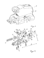
- FIG. 1 shows a shoe holding unit holder 10 which is connected to a base 2.
- the shoe holding unit holder 10 and the base 2 together form a shoe holding unit housing 1.
- the shoe holding unit housing 1 has a lateral opening or recess 1a, through which a part of the base 2 can be seen.
- the shoe holding unit housing 1 is formed in a known manner from plastic. Over the base 2, the shoe holding unit housing 1 can be axially fixed on the ski in a base structure, not shown.
- the shoe holding unit housing 1 shown is prepared to be connected to a machine, not shown, and forms together with the machine a heel holder of a trigger binding for a ski or a snowboard.
- the shoe holding unit housing 1 can be pushed onto the base 2 and is mounted on the base 2 linearly movable.
- an opening 1a is formed, the meaning of which will be described later.
- FIG. 2 shows in an exploded view, the base 2 with the parts of a locking mechanism with which the shoe holding unit housing 1 on the base 2 can be fixed axially.
- the locking mechanism comprises a locking member 3, a lever 4 and a starting spring 5. Furthermore, the locking mechanism comprises a coupling member 6, a spring element 7 and a pointer. 8
- the base 2 in this case forms the basic structure for the shoe holding unit housing 1, the locking mechanism is preferably arranged in the shoe holding unit housing 1 in this embodiment.
- the starting spring 5 is inserted into a receptacle 2 a in the base 2.
- the coupling member 6 is input so that formed in the base 2 rails 2 c engage in the recesses 6 a on the coupling member 6.
- the coupling member 6 can be moved in the axial direction A, but do not rotate in the base 2.
- the coupling member 6 has two arms 6b on Side walls 2d of the opening 2b abut.
- the coupling member 6 lies in the assembled locking mechanism between the starting spring 5 and the locking member 3, and is pressed by the starting spring 5 against the locking member 3. That is, in an axial movement of the locking member 3 or a compression or relaxation of the starting spring 5, the coupling member 6 is moved axially in the same direction and by the same distance as the locking member 3.
- the locking member 3 has substantially three sections: an axial end A front end portion 3a, a central main portion 3f and a rear end portion 3g in the axial direction A.
- the locking member 3 is inserted in the embodiment from below into the base 2, so that the front end portion 3a of the locking member 3 projects into the opening 2b.
- the central main section 3f has an engagement structure 3b, with axial webs 3c, and a locking structure 3d, with radial webs 3e.
- the locking member 3 is mounted in the base 2 such that at least the central main portion 3f, but preferably the entire locking member 3, relative to the base is not axially moved but can be pivoted relative to the base 2 about an axis pointing in the axial direction.
- the spring element 7 is arranged, which has two axially projecting A spring ends 7a and 7b.
- the coupling member 6 forms a kind of rigid housing for the spring element 7, which is thereby not compressed in an axial movement of the locking member 3.
- One of the spring ends 7b can be firmly connected, for example by positive engagement, with the coupling member 6, while the other spring end 7a can be connected to the locking member 3.
- the locking member 3 has a groove 3h, in which the end 7a of the spring element 7 can engage.
- the lever 4 can be pivotally mounted to the axle 11 in the base 2.
- the base 2 has two fasteners or bearings 2e, 2f in which the axle 11 on which the lever 4 is fastened or mounted is held or supported. That is, the axis 11 may be rotatably connected to the base 2 and the lever 4 is pivotally mounted on the axis 11, or the axis 11 is pivotally mounted in the base 2 and the lever 4 is rotatably connected to the axis 11.
- the lever 4 has a handle 4 a, which can be gripped by a user for operating the lever 4, a connecting portion 4 b, for connection to the axis 11, and an embodiment in the partial toothed ring engagement 4 c, for engaging in the engagement structure 3 b of the locking member. 3 with the axial webs 3c.
- a movement of the lever 4 in a vertical direction H the locking member 3 is pivoted, resulting in that the radial webs 3e of the locking structure 3d of the locking member 3 are moved out of a formed in the base structure not shown Martinezfeststell Geneva out, so that the shoe holding unit housing 1 in the embodiment together with the base 2 and thus the starting spring 5, the coupling member 6 and the locking member 3 can be moved axially.
- This position of the lever 4 is also referred to as a free-hold position. In the countermovement, the lever 4 again brings the fixing structure 3d into engagement with the counter-locking structure of the basic structure.
- the lever 4 is biased in a rest position in which the locking structure 3d and the counter-locking structure are engaged.
- the lever 2 is pivoted against the spring force of the spring element 7 in the vertical direction. In the pivoted position, the lever 4 must be held during the axial adjustment. Once the lever 4 is released, it is moved by the spring element 7 back to its rest position in which the locking member 3 is in the locking position.
- the spring element 7 moves the locking member 3 back into the locking position and the locking member 3 takes over the engagement structure 3b and the engagement 4c the lever 4 in the rest position.
- the spring element 7 may be connected to the lever 4, so that it would be moved by the spring element 7 in the rest position and thereby the locking member 3 would move into the locking position.
- the engagement 4c and the engagement structure 3b together form a cam mechanism and, in the exemplary embodiment shown, engage with each other in a rolling engagement.
- the lever 4 has a first lever arm 41 which extends from a pitch point of the connection engagement 4c and engagement structure 3b to the center of the axis 11 and a second lever arm 42 which comprises the handle 4a (see FIG. 2 ).
- the second lever arm 42 is longer in the embodiment than the first lever arm 41, whereby a force which attaches to the first lever arm 41 is translated into a larger force in the pitch point.
- the pointer 8 has a part-circular first portion 8a, wherein a circle center of the circle coincides with a rotation axis R1, in which the pointer 8 can be rotatably supported, for example, in the shoe holding unit housing 1.
- a second section 8b of the pointer 8 comprises a second rotation axis R2, in which the pointer 8 can be rotatably connected to the coupling member 6 or the locking member 3.
- a visual and / or tactile indicator 8d is formed in the form of a stroke, a notch or a raised portion.
- the pointer 8 and the free end 8c of the pointer 8 with the visual display 8d is, when it is installed in the shoe holding unit housing 1, through which in the FIG. 1 shown opening 1a laterally and can be seen and / or felt by a user.
- FIGS. 3 and 4 show the composite locking mechanism 12 from the lever side ( FIG. 3 ) and the pointer side ( FIG. 4 ).
- the starting spring 8 is supported via the coupling member 6 on the locking member 3 and pushes the coupling member 6 against the locking member 3.
- the coupling member 6 forms a housing for the spring element 7, which engages with the spring end 7a in the groove 3h of the locking member.
- the invisible spring end 7b is connected to the coupling member 6.
- the spring element 7 is a torsion spring in the exemplary embodiment.
- an engagement structure 3b of axially extending webs 3c is formed, which extend over a major part of the main portion 3f and form a curve joint with the engagement 4c of the lever 4.
- a movement of the lever 4 in a vertical direction H caused a rotation of the locking member 3 about an axis S1 parallel to the longitudinal axis L of the locking mechanism 12th
- the locking member 3 has at the free end of the rear end portion 3g on a tool engagement.
- a tool can be applied if, for example, the locking member 3 is clamped with the locking structure 3d in the counter-locking structure so that it can no longer be moved by means of the lever 4 from the locking position to the release position.
- the pointer 8 is connected to the coupling member 6 in the rotation axis R2 and can be connected to the shoe holding unit housing 1 in the rotation axis R1.
- the locking mechanism 12 is incorporated in the embodiment in the base 2, which is then connected to the shoe holding unit housing 1, wherein the base 2 and the shoe holding unit housing 1 together can form a shoe holding unit, for example a heel holder.
- FIG. 5 is a view from the top of the shoe holding unit housing 1. From this perspective, it can be seen clearly that the shoe holding unit housing 1 in addition to the already in the FIG. 1 illustrated opening 1a through which the pointer 8 can project laterally from the shoe holding unit housing 1, a further opening or recess 1b. Through this opening 1b, the lever 4 can laterally out of the Shoe holding unit housing 1 protrude so that it can be easily grasped by a user and moved in the vertical direction H.
- the gripping comprises grasping with the hand or a finger, gripping with a part of a ski pole and gripping with a tool.
- FIG. 6 shows an alternative embodiment, in which the starting spring 5 is directly connected to the locking member 3.
- the pointer 7 is connected directly to the locking member 3 in the second rotation axis R2.
- a linear movement of the locking member 3 can be implemented in a pivoting movement of the pointer 8.
- FIG. 7 shows in a view from behind the shoe holding unit housing 1 with the locking mechanism 12 of FIG. 2 , It can be seen that the locking structure 3d of the locking member 3 has radially extending webs 3e which protrude downward in the locking position of the locking member 3 shown, in order to be able to engage in corresponding anti-locking structures of a base structure.
- FIG. 8 shows an alternative embodiment in which the locking member 3 as known has a locking element with a thread as a locking structure. With a tool, the locking element 3 can be rotated, so that the locking structure can move axially in a corresponding known mating connection structure. Like in the FIG. 6 shown, this locking member 3 can be used to drive a pointer 8 for displaying a set spring force or release force of the starting spring 5.
- the FIG. 9 The first rotation axis R1 rotatably supports the pointer 8 in the shoe holding unit housing 1, while the second rotation axis R2 supports the pointer 8 in the coupling member 6.
- the bearing in the coupling member 6 is such that the pointer can move transversely to the longitudinal axis L of the locking mechanism 12.
- FIG. 10 shows in the same view as the FIG. 7 the connection between the lever 4 and the locking member 3.
- the lever 4 respectively the engagement 4c is in rolling engagement with the locking member 3 and the axial webs 3c of the engagement structure 3b.
- the lever 4 is in its rest position, since the locking structure 3d points in the direction of a base structure, not shown, with a counter-engagement structure.
- the spring end 7a of the spring element 7, which biases the lever 4 in the rest position and the locking member 3 in the locking position. If now the lever 4 is moved in the vertical direction H, the locking member 3 is rotated in the direction of the arrow via the rolling engagement of the engagement 4c with the engagement structure 3b.
- the locking structure is moved out of the locking position in the anti-locking structure, not shown, so that the shoe-holding unit housing 1 can now be displaced axially on the base structure, not shown.
- the lever 4 is held in the high position.
- the lever 4 is released and returned by means of the spring element 7, which is connected to the locking member 3 and the non-visible coupling member 6, together with the locking member 3 in the rest position in which the locking member the shoe holding unit housing 1 on the ski or snowboard axially defines.
- the pointer 8 indicates the actual determined by the shoe clamping force of the starting spring 5. If the visual display 8d is not visible on the pointer 8 or only visible at the edge, the shoe is removed from the release binding. Thereby, the start spring 5 returns to the set position in which the visual display 8d assumes a position in the center of the recess 1a. Subsequently, the lever 4 is actuated and the shoe holding unit housing 1 is moved axially in the direction that causes after a re-insertion of the shoe that the visual display 8 d is at least close to the center of the recess 1 a of the shoe holding unit housing 1. After a further check by inserting the ski boot into the release binding, the process can be repeated until the visual display 8d assumes an optimal, as central as possible position in the recess 1a.
- FIG. 11 shows the same view of the Schuhhalteaggregatgeophuses 1, as the FIG. 5 , In contrast to the picture of the FIG. 5 is now visible in the recess 1b of the lever 4.
- the lever 4 and the pointer 8 are arranged on opposite sides of the shoe holding unit housing 1, wherein arranged in the illustrated embodiment, the lever 4 on an inner side of the tripping, so that the two levers 4 face each other with strapped skis or on the snowboard.
- FIGS. 12 and 13 show the shoe holding unit housing 1 of FIG. 9 in two perspective views, once from the side with the pointer 8 in the recess 1a ( FIG. 12 ) and once from the side with the lever 4 in the recess 1b.
Landscapes
- Footwear And Its Accessory, Manufacturing Method And Apparatuses (AREA)
Applications Claiming Priority (1)
| Application Number | Priority Date | Filing Date | Title |
|---|---|---|---|
| DE102014104473.8A DE102014104473B4 (de) | 2014-03-28 | 2014-03-28 | Auslösebindung mit Hebel zur Festlegung und Freigabe eines Schuhhalteaggregats |
Publications (2)
| Publication Number | Publication Date |
|---|---|
| EP2923741A1 true EP2923741A1 (fr) | 2015-09-30 |
| EP2923741B1 EP2923741B1 (fr) | 2017-10-11 |
Family
ID=52736905
Family Applications (1)
| Application Number | Title | Priority Date | Filing Date |
|---|---|---|---|
| EP15160802.3A Active EP2923741B1 (fr) | 2014-03-28 | 2015-03-25 | Liaison détachable dotée d'un levier de fixation et de libération d'un support de chaussure |
Country Status (2)
| Country | Link |
|---|---|
| EP (1) | EP2923741B1 (fr) |
| DE (1) | DE102014104473B4 (fr) |
Cited By (1)
| Publication number | Priority date | Publication date | Assignee | Title |
|---|---|---|---|---|
| CN116687293A (zh) * | 2023-05-31 | 2023-09-05 | 北京顺造科技有限公司 | 地刷组件、表面清洁设备及地刷组件的清理方法 |
Citations (8)
| Publication number | Priority date | Publication date | Assignee | Title |
|---|---|---|---|---|
| EP1645310A1 (fr) * | 2004-10-05 | 2006-04-12 | MARKER Deutschland GmbH | Système de réglage d'une fixation de ski ou de snowboard |
| EP1652560A1 (fr) * | 2004-10-28 | 2006-05-03 | Look Fixations S.A. | Dispositif de réglage pour accessoire tel une butée avant de fixation de ski |
| EP1652559A1 (fr) * | 2004-10-28 | 2006-05-03 | Look Fixations S.A. | Dispositif de réglage pour accessoire tel une talonnière de fixation de ski |
| EP2082789A1 (fr) * | 2008-01-25 | 2009-07-29 | NORDICA S.p.A. | Dispositif de réglage de la distance entre le centre de moyens de fixation de fixations de ski |
| EP2147704A1 (fr) * | 2008-07-22 | 2010-01-27 | Skis Rossignol | Element de fixation pour planche de glisse avec rattrapage des jeux |
| EP2386333A1 (fr) * | 2010-05-05 | 2011-11-16 | Skis Rossignol | Elément de fixation à position réglable sur une planche de glisse sur neige |
| EP2444131A1 (fr) * | 2010-10-20 | 2012-04-25 | MARKER Deutschland GmbH | Fixation pour planche de glisse dotée d'unités de retenue réglables dans le sens de la longueur |
| DE102011086679A1 (de) | 2011-11-18 | 2013-05-23 | Marker Deutschland Gmbh | Bindung für Gleitbrett mit Stützglied |
-
2014
- 2014-03-28 DE DE102014104473.8A patent/DE102014104473B4/de active Active
-
2015
- 2015-03-25 EP EP15160802.3A patent/EP2923741B1/fr active Active
Patent Citations (8)
| Publication number | Priority date | Publication date | Assignee | Title |
|---|---|---|---|---|
| EP1645310A1 (fr) * | 2004-10-05 | 2006-04-12 | MARKER Deutschland GmbH | Système de réglage d'une fixation de ski ou de snowboard |
| EP1652560A1 (fr) * | 2004-10-28 | 2006-05-03 | Look Fixations S.A. | Dispositif de réglage pour accessoire tel une butée avant de fixation de ski |
| EP1652559A1 (fr) * | 2004-10-28 | 2006-05-03 | Look Fixations S.A. | Dispositif de réglage pour accessoire tel une talonnière de fixation de ski |
| EP2082789A1 (fr) * | 2008-01-25 | 2009-07-29 | NORDICA S.p.A. | Dispositif de réglage de la distance entre le centre de moyens de fixation de fixations de ski |
| EP2147704A1 (fr) * | 2008-07-22 | 2010-01-27 | Skis Rossignol | Element de fixation pour planche de glisse avec rattrapage des jeux |
| EP2386333A1 (fr) * | 2010-05-05 | 2011-11-16 | Skis Rossignol | Elément de fixation à position réglable sur une planche de glisse sur neige |
| EP2444131A1 (fr) * | 2010-10-20 | 2012-04-25 | MARKER Deutschland GmbH | Fixation pour planche de glisse dotée d'unités de retenue réglables dans le sens de la longueur |
| DE102011086679A1 (de) | 2011-11-18 | 2013-05-23 | Marker Deutschland Gmbh | Bindung für Gleitbrett mit Stützglied |
Cited By (1)
| Publication number | Priority date | Publication date | Assignee | Title |
|---|---|---|---|---|
| CN116687293A (zh) * | 2023-05-31 | 2023-09-05 | 北京顺造科技有限公司 | 地刷组件、表面清洁设备及地刷组件的清理方法 |
Also Published As
| Publication number | Publication date |
|---|---|
| DE102014104473B4 (de) | 2026-05-07 |
| DE102014104473A1 (de) | 2015-10-01 |
| EP2923741B1 (fr) | 2017-10-11 |
Similar Documents
| Publication | Publication Date | Title |
|---|---|---|
| DE2817627C2 (de) | Betätigungseinrichtung für eine Gangschaltung | |
| DE4018276C2 (de) | Sicherheitsbindung für Sportgeräte des alpinen Skisports | |
| DE2321669C3 (de) | Rollschuh | |
| DE19800321A1 (de) | Step-In-Bindung für Snowboards | |
| EP1131140A1 (fr) | Baton tel que baton de ski, baton de randonnee, etc. | |
| DE102013201725A1 (de) | Fersenhalter mit Verriegelungshebel | |
| DE19833508B4 (de) | Nadelwählvorrichtung, insbesondere zur Auswahl der Rippnadeln in Rundstrickmaschinen, Rundwirkmaschinen oder Strumpfwirkmaschinen zur Herstellung von Strick- und Strumpfwaren | |
| DE3341402A1 (de) | Verriegelbares dreibeinstativ-bein | |
| DE2934284A1 (de) | Spielgeraet | |
| EP3453433B1 (fr) | Talonnière avec élément fonctionnel | |
| EP1559455B1 (fr) | Fixation adaptée au ski de randonnée | |
| AT402794B (de) | Skibindung mit einer arretiervorrichtung für vorder- und/oder fersenbacken | |
| DE2218478A1 (de) | Skibindung mit einem vorderbacken und einem fersenautomat | |
| EP2923741B1 (fr) | Liaison détachable dotée d'un levier de fixation et de libération d'un support de chaussure | |
| DE202015105679U1 (de) | Einstellmittel für eine Rastanordnung zur Einstellung eines an einem Möbelkorpus aufgenommenen bewegbaren Möbelteils | |
| DE3021598A1 (de) | Drucktastenschalter | |
| DE202016003562U1 (de) | Anordnung mit einer Aktions-Spiralfeder zur Erzeugung einer Kraft und mit einem Rastmechanismus zum Auslösen der gespannten und zum Spannen der entspannten Aktions-Spiralfeder | |
| EP2303677A1 (fr) | Dispositif à coque repose-pieds d'un appareil de musculation | |
| DE2910508A1 (de) | Sicherheitsbindung fuer ski | |
| EP1888280A1 (fr) | Liaison entre deux parties d'outil | |
| DE1908880B2 (de) | Schaltvorrichtung fuer tragbare geraete | |
| DE19523566C1 (de) | Handbetätigter Ratschenschneider, insbesondere Kabelschneider | |
| EP2926876B1 (fr) | Vis de réglage avec rainure de came circulaire | |
| EP2088605B1 (fr) | Dispositif d'affichage | |
| EP1666308A2 (fr) | Console pour appareils à réglage universel |
Legal Events
| Date | Code | Title | Description |
|---|---|---|---|
| PUAI | Public reference made under article 153(3) epc to a published international application that has entered the european phase |
Free format text: ORIGINAL CODE: 0009012 |
|
| AK | Designated contracting states |
Kind code of ref document: A1 Designated state(s): AL AT BE BG CH CY CZ DE DK EE ES FI FR GB GR HR HU IE IS IT LI LT LU LV MC MK MT NL NO PL PT RO RS SE SI SK SM TR |
|
| AX | Request for extension of the european patent |
Extension state: BA ME |
|
| 17P | Request for examination filed |
Effective date: 20160309 |
|
| RBV | Designated contracting states (corrected) |
Designated state(s): AL AT BE BG CH CY CZ DE DK EE ES FI FR GB GR HR HU IE IS IT LI LT LU LV MC MK MT NL NO PL PT RO RS SE SI SK SM TR |
|
| GRAP | Despatch of communication of intention to grant a patent |
Free format text: ORIGINAL CODE: EPIDOSNIGR1 |
|
| INTG | Intention to grant announced |
Effective date: 20170509 |
|
| GRAS | Grant fee paid |
Free format text: ORIGINAL CODE: EPIDOSNIGR3 |
|
| GRAA | (expected) grant |
Free format text: ORIGINAL CODE: 0009210 |
|
| AK | Designated contracting states |
Kind code of ref document: B1 Designated state(s): AL AT BE BG CH CY CZ DE DK EE ES FI FR GB GR HR HU IE IS IT LI LT LU LV MC MK MT NL NO PL PT RO RS SE SI SK SM TR |
|
| REG | Reference to a national code |
Ref country code: GB Ref legal event code: FG4D Free format text: NOT ENGLISH |
|
| REG | Reference to a national code |
Ref country code: CH Ref legal event code: EP |
|
| REG | Reference to a national code |
Ref country code: IE Ref legal event code: FG4D Free format text: LANGUAGE OF EP DOCUMENT: GERMAN |
|
| REG | Reference to a national code |
Ref country code: AT Ref legal event code: REF Ref document number: 935527 Country of ref document: AT Kind code of ref document: T Effective date: 20171115 |
|
| REG | Reference to a national code |
Ref country code: DE Ref legal event code: R096 Ref document number: 502015002039 Country of ref document: DE Ref country code: CH Ref legal event code: NV Representative=s name: RIEDERER HASLER AND PARTNER PATENTANWAELTE AG, CH |
|
| REG | Reference to a national code |
Ref country code: NL Ref legal event code: MP Effective date: 20171011 |
|
| REG | Reference to a national code |
Ref country code: LT Ref legal event code: MG4D |
|
| PG25 | Lapsed in a contracting state [announced via postgrant information from national office to epo] |
Ref country code: NL Free format text: LAPSE BECAUSE OF FAILURE TO SUBMIT A TRANSLATION OF THE DESCRIPTION OR TO PAY THE FEE WITHIN THE PRESCRIBED TIME-LIMIT Effective date: 20171011 |
|
| PG25 | Lapsed in a contracting state [announced via postgrant information from national office to epo] |
Ref country code: ES Free format text: LAPSE BECAUSE OF FAILURE TO SUBMIT A TRANSLATION OF THE DESCRIPTION OR TO PAY THE FEE WITHIN THE PRESCRIBED TIME-LIMIT Effective date: 20171011 Ref country code: SE Free format text: LAPSE BECAUSE OF FAILURE TO SUBMIT A TRANSLATION OF THE DESCRIPTION OR TO PAY THE FEE WITHIN THE PRESCRIBED TIME-LIMIT Effective date: 20171011 Ref country code: NO Free format text: LAPSE BECAUSE OF FAILURE TO SUBMIT A TRANSLATION OF THE DESCRIPTION OR TO PAY THE FEE WITHIN THE PRESCRIBED TIME-LIMIT Effective date: 20180111 Ref country code: LT Free format text: LAPSE BECAUSE OF FAILURE TO SUBMIT A TRANSLATION OF THE DESCRIPTION OR TO PAY THE FEE WITHIN THE PRESCRIBED TIME-LIMIT Effective date: 20171011 Ref country code: FI Free format text: LAPSE BECAUSE OF FAILURE TO SUBMIT A TRANSLATION OF THE DESCRIPTION OR TO PAY THE FEE WITHIN THE PRESCRIBED TIME-LIMIT Effective date: 20171011 |
|
| PG25 | Lapsed in a contracting state [announced via postgrant information from national office to epo] |
Ref country code: HR Free format text: LAPSE BECAUSE OF FAILURE TO SUBMIT A TRANSLATION OF THE DESCRIPTION OR TO PAY THE FEE WITHIN THE PRESCRIBED TIME-LIMIT Effective date: 20171011 Ref country code: BG Free format text: LAPSE BECAUSE OF FAILURE TO SUBMIT A TRANSLATION OF THE DESCRIPTION OR TO PAY THE FEE WITHIN THE PRESCRIBED TIME-LIMIT Effective date: 20180111 Ref country code: RS Free format text: LAPSE BECAUSE OF FAILURE TO SUBMIT A TRANSLATION OF THE DESCRIPTION OR TO PAY THE FEE WITHIN THE PRESCRIBED TIME-LIMIT Effective date: 20171011 Ref country code: LV Free format text: LAPSE BECAUSE OF FAILURE TO SUBMIT A TRANSLATION OF THE DESCRIPTION OR TO PAY THE FEE WITHIN THE PRESCRIBED TIME-LIMIT Effective date: 20171011 Ref country code: IS Free format text: LAPSE BECAUSE OF FAILURE TO SUBMIT A TRANSLATION OF THE DESCRIPTION OR TO PAY THE FEE WITHIN THE PRESCRIBED TIME-LIMIT Effective date: 20180211 Ref country code: GR Free format text: LAPSE BECAUSE OF FAILURE TO SUBMIT A TRANSLATION OF THE DESCRIPTION OR TO PAY THE FEE WITHIN THE PRESCRIBED TIME-LIMIT Effective date: 20180112 |
|
| REG | Reference to a national code |
Ref country code: DE Ref legal event code: R097 Ref document number: 502015002039 Country of ref document: DE |
|
| PG25 | Lapsed in a contracting state [announced via postgrant information from national office to epo] |
Ref country code: CZ Free format text: LAPSE BECAUSE OF FAILURE TO SUBMIT A TRANSLATION OF THE DESCRIPTION OR TO PAY THE FEE WITHIN THE PRESCRIBED TIME-LIMIT Effective date: 20171011 Ref country code: SK Free format text: LAPSE BECAUSE OF FAILURE TO SUBMIT A TRANSLATION OF THE DESCRIPTION OR TO PAY THE FEE WITHIN THE PRESCRIBED TIME-LIMIT Effective date: 20171011 Ref country code: EE Free format text: LAPSE BECAUSE OF FAILURE TO SUBMIT A TRANSLATION OF THE DESCRIPTION OR TO PAY THE FEE WITHIN THE PRESCRIBED TIME-LIMIT Effective date: 20171011 Ref country code: DK Free format text: LAPSE BECAUSE OF FAILURE TO SUBMIT A TRANSLATION OF THE DESCRIPTION OR TO PAY THE FEE WITHIN THE PRESCRIBED TIME-LIMIT Effective date: 20171011 |
|
| PLBE | No opposition filed within time limit |
Free format text: ORIGINAL CODE: 0009261 |
|
| STAA | Information on the status of an ep patent application or granted ep patent |
Free format text: STATUS: NO OPPOSITION FILED WITHIN TIME LIMIT |
|
| PG25 | Lapsed in a contracting state [announced via postgrant information from national office to epo] |
Ref country code: RO Free format text: LAPSE BECAUSE OF FAILURE TO SUBMIT A TRANSLATION OF THE DESCRIPTION OR TO PAY THE FEE WITHIN THE PRESCRIBED TIME-LIMIT Effective date: 20171011 Ref country code: PL Free format text: LAPSE BECAUSE OF FAILURE TO SUBMIT A TRANSLATION OF THE DESCRIPTION OR TO PAY THE FEE WITHIN THE PRESCRIBED TIME-LIMIT Effective date: 20171011 Ref country code: SM Free format text: LAPSE BECAUSE OF FAILURE TO SUBMIT A TRANSLATION OF THE DESCRIPTION OR TO PAY THE FEE WITHIN THE PRESCRIBED TIME-LIMIT Effective date: 20171011 Ref country code: IT Free format text: LAPSE BECAUSE OF FAILURE TO SUBMIT A TRANSLATION OF THE DESCRIPTION OR TO PAY THE FEE WITHIN THE PRESCRIBED TIME-LIMIT Effective date: 20171011 |
|
| 26N | No opposition filed |
Effective date: 20180712 |
|
| PG25 | Lapsed in a contracting state [announced via postgrant information from national office to epo] |
Ref country code: MT Free format text: LAPSE BECAUSE OF FAILURE TO SUBMIT A TRANSLATION OF THE DESCRIPTION OR TO PAY THE FEE WITHIN THE PRESCRIBED TIME-LIMIT Effective date: 20171011 |
|
| PG25 | Lapsed in a contracting state [announced via postgrant information from national office to epo] |
Ref country code: SI Free format text: LAPSE BECAUSE OF FAILURE TO SUBMIT A TRANSLATION OF THE DESCRIPTION OR TO PAY THE FEE WITHIN THE PRESCRIBED TIME-LIMIT Effective date: 20171011 Ref country code: MC Free format text: LAPSE BECAUSE OF FAILURE TO SUBMIT A TRANSLATION OF THE DESCRIPTION OR TO PAY THE FEE WITHIN THE PRESCRIBED TIME-LIMIT Effective date: 20171011 |
|
| REG | Reference to a national code |
Ref country code: BE Ref legal event code: MM Effective date: 20180331 |
|
| REG | Reference to a national code |
Ref country code: IE Ref legal event code: MM4A |
|
| PG25 | Lapsed in a contracting state [announced via postgrant information from national office to epo] |
Ref country code: LU Free format text: LAPSE BECAUSE OF NON-PAYMENT OF DUE FEES Effective date: 20180325 |
|
| PG25 | Lapsed in a contracting state [announced via postgrant information from national office to epo] |
Ref country code: IE Free format text: LAPSE BECAUSE OF NON-PAYMENT OF DUE FEES Effective date: 20180325 |
|
| PG25 | Lapsed in a contracting state [announced via postgrant information from national office to epo] |
Ref country code: BE Free format text: LAPSE BECAUSE OF NON-PAYMENT OF DUE FEES Effective date: 20180331 |
|
| PG25 | Lapsed in a contracting state [announced via postgrant information from national office to epo] |
Ref country code: FR Free format text: LAPSE BECAUSE OF NON-PAYMENT OF DUE FEES Effective date: 20180331 |
|
| GBPC | Gb: european patent ceased through non-payment of renewal fee |
Effective date: 20190325 |
|
| PG25 | Lapsed in a contracting state [announced via postgrant information from national office to epo] |
Ref country code: GB Free format text: LAPSE BECAUSE OF NON-PAYMENT OF DUE FEES Effective date: 20190325 |
|
| PG25 | Lapsed in a contracting state [announced via postgrant information from national office to epo] |
Ref country code: TR Free format text: LAPSE BECAUSE OF FAILURE TO SUBMIT A TRANSLATION OF THE DESCRIPTION OR TO PAY THE FEE WITHIN THE PRESCRIBED TIME-LIMIT Effective date: 20171011 |
|
| PG25 | Lapsed in a contracting state [announced via postgrant information from national office to epo] |
Ref country code: PT Free format text: LAPSE BECAUSE OF FAILURE TO SUBMIT A TRANSLATION OF THE DESCRIPTION OR TO PAY THE FEE WITHIN THE PRESCRIBED TIME-LIMIT Effective date: 20171011 |
|
| PG25 | Lapsed in a contracting state [announced via postgrant information from national office to epo] |
Ref country code: MK Free format text: LAPSE BECAUSE OF NON-PAYMENT OF DUE FEES Effective date: 20171011 Ref country code: HU Free format text: LAPSE BECAUSE OF FAILURE TO SUBMIT A TRANSLATION OF THE DESCRIPTION OR TO PAY THE FEE WITHIN THE PRESCRIBED TIME-LIMIT; INVALID AB INITIO Effective date: 20150325 Ref country code: CY Free format text: LAPSE BECAUSE OF FAILURE TO SUBMIT A TRANSLATION OF THE DESCRIPTION OR TO PAY THE FEE WITHIN THE PRESCRIBED TIME-LIMIT Effective date: 20171011 |
|
| PG25 | Lapsed in a contracting state [announced via postgrant information from national office to epo] |
Ref country code: AL Free format text: LAPSE BECAUSE OF FAILURE TO SUBMIT A TRANSLATION OF THE DESCRIPTION OR TO PAY THE FEE WITHIN THE PRESCRIBED TIME-LIMIT Effective date: 20171011 |
|
| P01 | Opt-out of the competence of the unified patent court (upc) registered |
Effective date: 20230515 |
|
| PGFP | Annual fee paid to national office [announced via postgrant information from national office to epo] |
Ref country code: DE Payment date: 20250331 Year of fee payment: 11 |
|
| PGFP | Annual fee paid to national office [announced via postgrant information from national office to epo] |
Ref country code: CH Payment date: 20250401 Year of fee payment: 11 |
|
| REG | Reference to a national code |
Ref country code: CH Ref legal event code: U11 Free format text: ST27 STATUS EVENT CODE: U-0-0-U10-U11 (AS PROVIDED BY THE NATIONAL OFFICE) Effective date: 20260401 |
|
| PGFP | Annual fee paid to national office [announced via postgrant information from national office to epo] |
Ref country code: AT Payment date: 20260319 Year of fee payment: 12 |