EP2926701B1 - Gril en forme de plaque ayant une zone de cuisson entièrement plate - Google Patents
Gril en forme de plaque ayant une zone de cuisson entièrement plate Download PDFInfo
- Publication number
- EP2926701B1 EP2926701B1 EP15000951.2A EP15000951A EP2926701B1 EP 2926701 B1 EP2926701 B1 EP 2926701B1 EP 15000951 A EP15000951 A EP 15000951A EP 2926701 B1 EP2926701 B1 EP 2926701B1
- Authority
- EP
- European Patent Office
- Prior art keywords
- plate
- grill
- operating
- shaped
- guiding
- Prior art date
- Legal status (The legal status is an assumption and is not a legal conclusion. Google has not performed a legal analysis and makes no representation as to the accuracy of the status listed.)
- Active
Links
Images




Classifications
-
- A—HUMAN NECESSITIES
- A47—FURNITURE; DOMESTIC ARTICLES OR APPLIANCES; COFFEE MILLS; SPICE MILLS; SUCTION CLEANERS IN GENERAL
- A47J—KITCHEN EQUIPMENT; COFFEE MILLS; SPICE MILLS; APPARATUS FOR MAKING BEVERAGES
- A47J37/00—Baking; Roasting; Grilling; Frying
- A47J37/06—Roasters; Grills; Sandwich grills
- A47J37/067—Horizontally disposed broiling griddles
- A47J37/0676—Horizontally disposed broiling griddles electrically heated
-
- A—HUMAN NECESSITIES
- A47—FURNITURE; DOMESTIC ARTICLES OR APPLIANCES; COFFEE MILLS; SPICE MILLS; SUCTION CLEANERS IN GENERAL
- A47J—KITCHEN EQUIPMENT; COFFEE MILLS; SPICE MILLS; APPARATUS FOR MAKING BEVERAGES
- A47J37/00—Baking; Roasting; Grilling; Frying
- A47J37/06—Roasters; Grills; Sandwich grills
Definitions
- the present invention relates to a plate-shaped grill (1), in particular a Tepan stainless steel grill, with the features specified in the preamble of claim 1.
- Object of the present invention is therefore to provide a plate-shaped grill (1), which is a heating of the grill plate (2) in full-surface, locally uniform and locally simultaneous manner without local temperature spreads allowed.
- the entire underside of the grill plate (2) can be in full or indirect connection with one or more surface heating elements (5).
- the surface heating element (5) can be designed for full-area, uniform, simultaneous heating of the grill plate (2) which is free of temperature spread, for example in the form of a surface heating element (5), in which a resistance wire is inserted into one Layer (35) of mica fragments pressed with synthetic resins is closely meshed.
- this surface heating layer (35) may be sandwiched between an overhead aluminum plate (34) and an underlying aluminum plate (36).
- FIG. 1 can be in the plate-shaped grill (1) according to the invention, the field (30) for receiving the grill plate (2) integrally formed with a control panel (3).
- both the field (30) for receiving the grill plate (2) and the control panel (3) can be made of metal and in one piece or in several parts.
- control panel (3) either one or more capacitive input devices (32) for the control and regulation of mecanical elements (5) or - in addition to or instead - one or more control devices (4), each with a rotatable control knob (27) wear.
- FIGS. 1 . 2 . 6 and 8th between the field (30) for receiving the grill plate (2) on the one hand and the control panel (3) for receiving the one or more capacitive input devices (32) or control devices (4) on the other hand one or more consecutively formed, one each or multi-part, slots (31) in the field (30) and the control panel (3) forming metal plate may be provided.
- the longitudinal axes of the slot (s) (31) may be aligned, for example, parallel to that edge (29) of the panel (30) for receiving the grill plate (2) pointing in the direction of the control panel (3).
- the elongated holes (31) can have a length in the range of 5.0% to 95.0%, preferably in the range of 10.0% to 90.0%, in particular in the range of 15.0% to 85.0%, centered across the width (46) of the grill (1) continuously or in sections - at least before or before the capacitive input devices or operating devices (4) - extend.
- the at least one slot (31) may have a width which is in the range of 1.5 mm to 25.0 mm, preferably in the range of 1.7 mm to 21.0 mm, in particular in the range of 2.0 mm to 20, 0 mm.
- FIG. 8 shows that in the at least one single or multi-part slot (31) at least one single or multi-part heat insulation insert (37) or a trim strip can be provided.
- This heat insulation insert (37) or the trim strip can in particular preferred embodiments of the grill according to the invention (1), the front (11) of the control panel (3) in the range of 0.1 mm to 20.0 mm, preferably in the Range of 0.2 mm to 18.0 mm, especially in the range from 0.3 mm to 15.0 mm, in the form of a projection (39) projecting upwards.
- FIG. 8 shows that the pin (38) of the at least one heat-insulating insert (37) - or the decorative strip used in its place - with the bottom (10) of the control panel (3) may be in communication.
- the at least one heat-insulating insert (37) - or the decorative strip used in its place - be made of opaque material, such as plastic or ceramic.
- the at least one heat insulation insert (37) - or the trim strip used in its place - be transparent and possibly by means of one or more single or multi-part lighting white or colored light, be designed.
- each operating device (4) may include a liquid-tight and rotative solid and rigid with the control panel (3) in connection, cap-shaped sealing and guiding element (8).
- a pivotable about a perpendicular to the top (11) of the control panel (3) aligned rotation axis (47) reversibly back and forth rotary control knob (27) of the operating device (4) reversibly removable on this pedestal-shaped sealing and guiding element (8) be provided.
- This rotatable control knob (27) of the operating device (4) can be reversibly connected to a parallel to the axis of rotation (47) aligned axis (9) of the operating device (4).
- control panel (3) depending on the desired number of operating devices (4) - one or more circular recesses (6), through which in each case the pin (7) of a guide and sealing element (8) - in the direction the underside (10) of the control panel (3) - can be passed.
- the guide and sealing element (8) in the direction of the top (11) of the control panel (3) have a projection (12).
- this projection (12) of the guide and sealing element (8) can project beyond the upper side (11) of the control panel (3).
- the upwardly projecting projection (12) of the rotationally fixed guide and sealing element (8) can have a central recess (15) for play-free reception and play-free guidance of a downwardly pointing, central pin (16) of the rotatable control knob (27) of the operating device (4) - and / or for the passage of the axis (9) of the operating device (4) - have.
- FIG. 3 shows that also the downwardly directed pin (7) of the rotationally fixed guide and seal member (8) may have a central recess (19) for play-free guidance of the axis (9) of the operating device (4).
- transition between these two central recesses (15, 19) may be smooth or stepped.
- the outer circumference of the downwardly directed pin (7) of the rotationally fixed guide and sealing element (8) either a thread (24) for engagement of a nut (25) or one or a plurality of latching devices (26) - for the positive and / or non-positive attachment of the rotationally fixed seal and guide element (8) in the area around the circular recess (6) of the control panel (3) - wear.
- the base-like, rotationally fixed sealing and guiding element (8) - secured against rotation about the axis of rotation (47) - liquid-tight with the control panel (3) are in communication.
- the rotatable control knob (27) of the operating device (4) hat-shaped or disc-shaped - rotatable about the axis of rotation (47) - reversibly sit on the rotationally fixed seal and guide element (8) or rest or be associated with this.
- the rotatable control knob (27) of the operating device (4) and the fixed, cap-shaped guide and sealing element (8) - depending on or independently of each other - be transparent and optionally by means of one or more single or multi-part lighting white or colored Be made emitting light.
- the underside (21) of the projection (12) of the pedestal in terms of rotationally fixed sealing and guiding element (8) may be smooth.
- this underside (21) of the projection (12) has an annular circumferential groove (49) for receiving a resilient O-ring (FIG. 3) which seals against the control panel (3). 50) (see in particular FIG. 3 ).
- the laterally encircling outer wall of the socket-shaped, rotatably fixed guide and sealing element (8) can be smooth and straight.
- the laterally encircling outer wall of the pedestal, in rotationally fixed guide and sealing element (8) - for the engagement of the edge wall downwardly oriented, circumferential wall of the rotary control knob (27) of the operating device (4) - be formed step-shaped (see especially Figures 3 and 4 ).
- FIG. 3 shows that in the case of the plate-shaped grill (1) according to the invention, the protrusion (12) of the rotationally fixed, pedestal-shaped guiding and sealing element (8) can project beyond the upper side (11) of the control panel (3) to an extent (13), which is in a range of 3.0 mm to 40.0 mm, preferably in the range of 4.0 mm to 30.0 mm, in particular in the range of 5.0 mm to 25.0 mm.
- the upwardly facing projection (12) of the rotationally fixed guiding and sealing element (8) may, for example, have a width (14) in the range of 20.0 mm to 60.0 mm, preferably in the range of 25.0 mm to 55.0 mm, in particular in the range of 27.0 mm to 50.0 mm.
- the width (17) of the central recess (15) of the upwardly directed projection (12) of the rotationally fixed guide and sealing element (8) may be, for example, in the range of 5.0 mm to 40.0 mm, preferably in the Range from 10.0 mm to 30.0 mm, in particular in the range from 12.0 mm to 25.0 mm.
- the width (18) of the central recess (19) of the downwardly directed pin (7) of the rotationally fixed seal and guide element (8), for example, to the diameter of the axis (9) of the operating device (4) be adjusted without play and for example, in the range of 5.0 mm to 30.0 mm, preferably in the range of 6.0 mm to 25.0 mm, in particular in the range of 7.0 mm to 20.0 mm.
- the distance (20) between the underside (21) of the upwardly facing projection (12) of the rotationally fixed sealing and guiding element (8) on the one hand and the underside (22) of the downwardly pointing pin (7) of the rotationally fixed seal and guide member (8) on the other hand for example, in the range of 3.0 mm to 30.0 mm, preferably in the range of 4.0 mm to 25.0 mm, in particular in the range of 5.0 mm to 20.0 mm, lie.
- the width (23) of the downwardly pointing pin (7) of the rotationally fixed sealing and guiding element (8) may, for example, in the range of 7.0 mm to 32.0 mm, preferably in the range of 8.0 mm to 27.0 mm, in particular in the range of 9.0 mm to 22.0 mm.
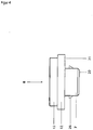
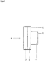
- FIGS. 7 and 9 shows that in the case of the plate-shaped grill according to the invention (1) the edge profile (28) of the entire surface, evenly, heated simultaneously and without temperature spread grill plate (2) - between the upper edge (29) of the field (30) for receiving the grill plate ( 2) on the one hand and the grill plate (2) lowered relative to the upper edge (29), on the other hand, can be formed in the shape of a slanted, stretched, smooth and kink-free letter "S".
- the trough-like lowering of the lower lying grill plate (2) opposite the higher edge (29) of the field (30) is in particular by the fact that the edge (29) of the field (30) and the grill plate (2) are integrally formed and the grill plate ( 2) is lowered in a deep drawing process relative to the edge (29) of the field (30).
- FIG. 9 shows that the radius (43) of that curvature (42) which is close to the edge (29) of the field (30) for receiving the grill plate (2) and the radius (41) of the grill plate near curvature (40), for example, respectively in the range of 2.0 mm to 20.0 mm, preferably in the range of 3.0 mm to 15.0 mm, in particular in the range of 4.0 mm to 10.0 mm.
- these two radii (43, 41) can be the same.
- these two radii (41; 43) may be different from each other.
- FIGS. 7 and 9 shows that between the overhead curvature (42) and the underlying lower curve (40) a straight and smooth formed connecting element (44) may be provided.
- this straight and smooth connecting element (44) with an imaginary vertical line through the center of the straight and smooth connecting element (44) can enclose an angle ⁇ in the range of, for example, 88 ° to 1 °, preferably in the range from 85 ° to 5 °, in particular in the range of 80 ° to 10 °.
- the plate-shaped grill (1) may be in the - instead of or in addition to the operating device (4) with rotatable control knob (27) - optionally existing capacitive means for controlling and / or regulating the professionnfilettis (5) to a user-actuated , Capacitive touch screen of the type "Projected Capacitive Touch" act.
- two touch-sensitive sensors can be located on top of each other, two conductive layers that are insulated from each other.
- These two insulated, conductive planes can be printed, for example, with a manufacturer-specific pattern, preferably in the form of capacitors.
- these touch sensors configured in this way can be provided on the underside (10) of the control panel (3).
- a plate-shaped grill (1) is provided, which allows heating of the grill plate (2) in full-surface, locally uniform and spatially simultaneous manner without local temperature spreads.
- the grill plate (2) now - excluding temporal delays and local temperature spreads especially during the heating phase - all over, locally evenly, locally simultaneously, without delay and heated without any local temperature spread.
Landscapes
- Engineering & Computer Science (AREA)
- Food Science & Technology (AREA)
- Baking, Grill, Roasting (AREA)
Claims (8)
- Grill en forme de plaque (1), l'ensemble de la face inférieure de la plaque de grill (2) étant en liaison indirecte ou directe, sur toute sa surface, avec un ou plusieurs éléments chauffants plats (5), de sorte que toute la surface de la plaque de grill (2) peut être chauffée de façon absolument uniforme et simultanée, caractérisé en ce que l'élément chauffant plat (5) servant au chauffage uniforme et simultané de toute la surface de la plaque de grill (2) est un élément chauffant plat (5) pour lequel un fil électrique résistif est inséré étroitement dans une couche (35) composée de fragments de mica pressés avec des résines synthétiques, cette couche (35) étant située en sandwich entre une plaque d'aluminium supérieure (34) et une plaque d'aluminium inférieure (36) et cet élément chauffant plat (5) en sandwich étant relié indirectement ou directement à la face arrière de la plaque de grill (2), et chauffant toute la surface de celle-ci de manière uniforme et simultanée.
- Grill en forme de plaque (1) selon la revendication 1, caractérisé en ce que son champ (30) destiné à recevoir la plaque de grill (2) est réalisé d'une seule pièce avec un panneau de commande (3), le champ (30) destiné à recevoir la plaque de grill (2) et le panneau de commande (3) étant fabriqués en métal, et le panneau de commande (3) portant soit un ou plusieurs dispositifs d'entrée capacitifs (32) pour la commande et la régulation de l'élément chauffant plat (5), soit, en lieu et place de cela, un ou plusieurs dispositifs de commande (4).
- Grill en forme de plaque (1) selon l'une quelconque des revendications précédentes, caractérisé en ce qu'entre le champ (30) destiné à recevoir la plaque de grill (2) d'une part et le panneau de commande (3) destiné à recevoir le ou les dispositifs d'entrée capacitifs (32) ou les dispositifs de commande (4) d'autre part, un ou plusieurs trous oblongs (31), dans chaque cas en une ou plusieurs parties, et ménagés les uns derrière les autres, sont prévus dans la plaque métallique formant le champ (30) et le panneau de commande (3), plaque dont les axes longitudinaux sont orientés parallèlement au bord (29) du champ (30), destiné à recevoir la plaque de grill (2), qui est orienté en direction du panneau de commande (3), les trous oblongs (31) s'étendant avec une longueur dans la plage de 5,0 % à 95,0 % de manière centrée sur toute la largeur (46) du grill (1), en continu ou sur certaines parties, au moins devant le ou les dispositifs d'entrée capacitifs ou les dispositifs de commande (4), le ou les trous oblongs (31) présentant une largeur qui se situe dans la plage de 1,5 mm à 25,0 mm et au moins un insert d'isolation thermique (37) en une ou plusieurs parties, lequel fait saillie vers le haut de la face avant (11) du panneau de commande (3) dans la plage de 0,1 mm à 20,0 mm sous la forme d'un dépassement (39), étant prévu dans le ou les trous oblongs (31) en une ou plusieurs parties, tandis que le tourillon (38) de l'insert ou des inserts d'isolation thermique (37) est relié à la face inférieure (10) du panneau de commande (3), l'insert ou les inserts d'isolation thermique (37) étant opaques ou transparents et, le cas échéant, émettant une lumière blanche ou colorée au moyen d'un ou de plusieurs éclairages en une ou plusieurs parties.
- Grill en forme de plaque (1) selon l'une quelconque des revendications précédentes, caractérisé en ce que chaque dispositif de commande (4) comprend un élément d'étanchéité et de guidage (8) en forme de socle relié de manière étanche au fluide et fixe en terme de rotation au panneau de commande (3), élément sur lequel un bouton de commande (27) du dispositif de commande (4), pouvant être amené en rotation en va-et-vient de manière réversible autour d'un axe de rotation (47) orienté perpendiculairement à la face supérieure (11) du panneau de commande (3), peut être retiré de manière réversible, lequel bouton est relié de manière réversible à un axe (9) du dispositif de commande (4) orienté parallèlement à l'axe de rotation (47), l'axe (9) du dispositif de commande (4) et le bouton de commande (27) du dispositif de commande (4) étant retenus sans jeu par l'élément d'étanchéité et de guidage (8) en forme de socle, fixe en terme de rotation, et étant guidés sans jeu pendant la rotation du bouton de commande (27) du dispositif de commande (4).
- Grill en forme de plaque (1) selon l'une quelconque des revendications précédentes, caractérisé en ce que le panneau de commande (3), en fonction du nombre souhaité de dispositifs de commande (4), comprend un ou plusieurs évidements ronds (6) à travers lesquels, dans chaque cas, le tourillon (7) d'un élément de guidage et d'étanchéité (8) peut être guidé en direction de la face inférieure (10) du panneau de commande (3), tandis que l'élément de guidage et d'étanchéité (8) forme une partie saillante (12) en direction de la face supérieure (11) du panneau de commande (3), qui fait saillie vers le haut de la face supérieure (11) du panneau de commande (3), la partie saillante (12) comprenant un évidement central (15) pour la réception sans jeu et pour le guidage sans jeu du tourillon central (16) du bouton de commande (27) du dispositif de commande (4) et/ou pour le guidage de l'axe (9) du dispositif de commande (4) à travers celui-ci, le tourillon (7) de l'élément de guidage et d'étanchéité (8) possédant un évidement central (19) pour le guidage sans jeu de l'axe (9) du dispositif de commande (4), le passage entre ces deux évidements centraux (15 ; 19) étant lisse ou étagé, la périphérie extérieure du tourillon (7) de l'élément de guidage et d'étanchéité (8) portant soit un filet (24) pour la mise en prise avec un écrou (25) soit un ou plusieurs dispositifs d'encliquetage (26), pour le montage par coopération de formes et/ou à force de l'élément de guidage et d'étanchéité (8) dans la zone située autour de l'évidement (6) du panneau de commande (3), l'élément de guidage et d'étanchéité (8) du type socle étant relié de manière étanche au fluide au panneau de commande (3), en étant empêché de tourner autour de l'axe de rotation (47), tandis que le bouton de commande (27) du dispositif de commande (4) repose ou se situe de manière réversible sur l'élément de guidage et d'étanchéité (8) ou est relié à celui-ci en formant un chapeau ou un disque, de manière à pouvoir tourner autour de l'axe de rotation (47), le bouton de commande (27) rotatif du dispositif de commande (4) et l'élément de guidage et d'étanchéité (8) fixe, en forme de socle, respectivement indépendamment l'un de l'autre, étant opaques ou transparents et, le cas échéant, émettant une lumière blanche ou colorée au moyen d'un ou de plusieurs éclairages en une ou plusieurs parties, la face inférieure (21) de la partie saillante (12) de l'élément de guidage et d'étanchéité (8) en forme de socle étant lisse ou présentant une rainure (49) annulairement périphérique pour la réception d'un joint torique (50) et la paroi extérieure latéralement périphérique de l'élément de guidage et d'étanchéité (8) en forme de socle, fixe en terme de rotation, étant lisse et rectiligne ou, pour la mise en prise avec la paroi périphérique, orientée vers le bas à la façon d'un chapeau, du bouton de commande (27) rotatif du dispositif de commande (4), étagé.
- Grill en forme de plaque (1) selon l'une quelconque des revendications précédentes, caractérisé en ce que la partie saillante (12) de l'élément de guidage et d'étanchéité (8) en forme de socle, fixe en terme de rotation, fait saillie de la face supérieure (11) du panneau de commande (3) d'une ampleur (13) qui se situe dans une plage allant de 3,0 mm à 40,0 mm, la partie saillante (12) présentant une largeur (14) dans la plage de 20,0 mm à 60,0 mm, la largeur (17) de l'évidement central (15) de la partie saillante (12) de l'élément de guidage et d'étanchéité (8) se situant dans la plage de 5,0 mm à 40,0 mm, la largeur (18) de l'évidement central (19) du tourillon (7) de l'élément de guidage et d'étanchéité (8) étant adaptée sans jeu au diamètre de l'axe (9) du dispositif de commande (4) et se situant dans la plage de 5,0 mm à 30,0 mm, l'écart (20) entre la face inférieure (21) de la partie saillante (12) de l'élément de guidage et d'étanchéité (8) d'une part et la face inférieure (22) du tourillon (7) de l'élément de guidage et d'étanchéité (8) d'autre part se situant dans la plage de 3,0 mm à 30,0 mm et la largeur (23) du tourillon (7) de l'élément de guidage et d'étanchéité (8) se situant dans la plage de 7,0 mm à 32,0 mm.
- Grill en forme de plaque (1) selon l'une quelconque des revendications précédentes, caractérisé en ce que le profil marginal (28) de la plaque de grill (2) chauffée sur toute sa surface de manière uniforme et simultanée, entre le bord supérieur (29) du champ (30) destiné à recevoir la plaque de grill (2) d'une part et la plaque de grill (2) abaissée par rapport au bord supérieur (29) d'autre part, est réalisé sous la forme d'une lettre « S » inclinée, étirée, lisse et sans rupture de courbe, le rayon (43) de la courbure (42) qui est proche du bord (29) du champ (30) destiné à recevoir la plaque de grill (2) et le rayon (41) de la courbure (40) proche de la plaque de grill se situant chacun dans la plage de 2,0 mm à 20,0 mm, ces deux rayons (43 ; 41) étant identiques ou différents l'un de l'autre, et un élément de liaison (44) droit, qui forme avec une ligne verticale imaginaire passant par le centre de l'élément de liaison (44) droit un angle α qui se situe dans la plage de 88° à 1°, étant prévu entre la courbure supérieure (42) et la courbure (40) plus basse que celle-ci.
- Grill en forme de plaque (1) selon l'une quelconque des revendications précédentes, caractérisé en ce que le dispositif capacitif de commande et/ou de régulation de l'élément chauffant plat (5), présent le cas échéant, en lieu et place ou en plus du dispositif de commande (4), est un écran tactile capacitif pouvant être actionné par l'utilisateur, du type « tactile capacitif projeté », deux plans conducteurs isolés l'un de l'autre, en tant que capteurs tactiles, étant superposés, sur lesquels sont imprimés des motifs spécifiques au fabricant prenant la forme de condensateurs, ces capteurs tactiles étant prévus sur la face inférieure (10) du panneau de commande (3), dans lequel, lorsqu'un doigt se rapproche de la surface tactile sur la face supérieure (11) du panneau de commande (3) ou la touche, une charge électrique est retirée des condensateurs, et des champs capacitifs sont projetés à travers le panneau de commande (3), une électronique identifiant cette modification comme un contact.
Applications Claiming Priority (1)
| Application Number | Priority Date | Filing Date | Title |
|---|---|---|---|
| DE202014002850.8U DE202014002850U1 (de) | 2014-04-03 | 2014-04-03 | Plattenförmiger Grill mit vollflächiger Kochzone |
Publications (2)
| Publication Number | Publication Date |
|---|---|
| EP2926701A1 EP2926701A1 (fr) | 2015-10-07 |
| EP2926701B1 true EP2926701B1 (fr) | 2017-08-23 |
Family
ID=50726443
Family Applications (1)
| Application Number | Title | Priority Date | Filing Date |
|---|---|---|---|
| EP15000951.2A Active EP2926701B1 (fr) | 2014-04-03 | 2015-04-01 | Gril en forme de plaque ayant une zone de cuisson entièrement plate |
Country Status (3)
| Country | Link |
|---|---|
| EP (1) | EP2926701B1 (fr) |
| DE (1) | DE202014002850U1 (fr) |
| ES (1) | ES2642784T3 (fr) |
Family Cites Families (1)
| Publication number | Priority date | Publication date | Assignee | Title |
|---|---|---|---|---|
| DE9420656U1 (de) * | 1994-12-23 | 1995-03-30 | Schacht, Paul, 80796 München | Vorrichtung zum Grillen, Garen, Wärmen und/oder Warmhalten von Speisen |
-
2014
- 2014-04-03 DE DE202014002850.8U patent/DE202014002850U1/de not_active Expired - Lifetime
-
2015
- 2015-04-01 EP EP15000951.2A patent/EP2926701B1/fr active Active
- 2015-04-01 ES ES15000951.2T patent/ES2642784T3/es active Active
Non-Patent Citations (1)
| Title |
|---|
| None * |
Also Published As
| Publication number | Publication date |
|---|---|
| EP2926701A1 (fr) | 2015-10-07 |
| DE202014002850U1 (de) | 2014-04-28 |
| ES2642784T3 (es) | 2017-11-20 |
Similar Documents
| Publication | Publication Date | Title |
|---|---|---|
| DE102016101008B4 (de) | Kochgerät | |
| DE3545442C2 (fr) | ||
| DE2653389C2 (de) | Kochmulde | |
| DE2007145A1 (de) | Kocheinheit | |
| EP1834507A1 (fr) | Plaque de cuisson comprenant un eclairage et procede pour eclairer une plaque de cuisson | |
| EP2959585B1 (fr) | Unité de commande pour une cafetière électrique | |
| DE19610921A1 (de) | Versenkbares Bedienelement | |
| EP3300455A1 (fr) | Plaque de cuisson et procédé de positionnement d'un dispositif de chauffage sur plaque de cuisson | |
| DE202006003115U1 (de) | Bedieneinrichtung für ein Elektrogerät, Sensorelement dafür und damit versehenes Elektrogerät | |
| EP2182636A2 (fr) | Dispositif de commande d'un appareil ménager | |
| EP2837891B1 (fr) | Plaque de cuisson | |
| WO2019137742A1 (fr) | Dispositif de commande pour un appareil électroménager | |
| WO2015104194A1 (fr) | Dispositif de commande d'appareil ménager | |
| WO2008003566A2 (fr) | Table de cuisson | |
| EP2926701A1 (fr) | Gril en forme de plaque ayant une zone de cuisson entièrement plate | |
| EP2156706B1 (fr) | Table de cuisson | |
| DE102014200888A1 (de) | Bedienvorrichtung für ein Haushaltsgerät mit einem Kratzschutzelement an einer Unterseite eines abnehmbaren Bedienelements sowie Haushaltsgerät mit einer derartigen Bedienvorrichtung | |
| EP3470741A1 (fr) | Système de plaque de cuisson | |
| DE2407582A1 (de) | Einbaukochmulde aus glas oder dgl. mit mehreren kochstellen fuer einbaukuechenmoebel | |
| DE19810438A1 (de) | Herd mit vier Kochzonen und einem Back- und Bratofen | |
| DE10211520A1 (de) | Glaskeramik-Kochfläche | |
| DE102008052815A1 (de) | Kochfeldplatte für Kochfeld und Kochfeld | |
| EP2645002B1 (fr) | Plaque de cuisson | |
| DE102005053928B4 (de) | Bedienelement für Haushaltsgerät | |
| EP2072694B1 (fr) | Evier |
Legal Events
| Date | Code | Title | Description |
|---|---|---|---|
| PUAI | Public reference made under article 153(3) epc to a published international application that has entered the european phase |
Free format text: ORIGINAL CODE: 0009012 |
|
| 17P | Request for examination filed |
Effective date: 20150409 |
|
| AK | Designated contracting states |
Kind code of ref document: A1 Designated state(s): AL AT BE BG CH CY CZ DE DK EE ES FI FR GB GR HR HU IE IS IT LI LT LU LV MC MK MT NL NO PL PT RO RS SE SI SK SM TR |
|
| AX | Request for extension of the european patent |
Extension state: BA ME |
|
| GRAP | Despatch of communication of intention to grant a patent |
Free format text: ORIGINAL CODE: EPIDOSNIGR1 |
|
| INTG | Intention to grant announced |
Effective date: 20170404 |
|
| GRAS | Grant fee paid |
Free format text: ORIGINAL CODE: EPIDOSNIGR3 |
|
| GRAA | (expected) grant |
Free format text: ORIGINAL CODE: 0009210 |
|
| AK | Designated contracting states |
Kind code of ref document: B1 Designated state(s): AL AT BE BG CH CY CZ DE DK EE ES FI FR GB GR HR HU IE IS IT LI LT LU LV MC MK MT NL NO PL PT RO RS SE SI SK SM TR |
|
| REG | Reference to a national code |
Ref country code: GB Ref legal event code: FG4D Free format text: NOT ENGLISH |
|
| REG | Reference to a national code |
Ref country code: CH Ref legal event code: EP |
|
| REG | Reference to a national code |
Ref country code: AT Ref legal event code: REF Ref document number: 920375 Country of ref document: AT Kind code of ref document: T Effective date: 20170915 |
|
| REG | Reference to a national code |
Ref country code: IE Ref legal event code: FG4D Free format text: LANGUAGE OF EP DOCUMENT: GERMAN |
|
| REG | Reference to a national code |
Ref country code: DE Ref legal event code: R096 Ref document number: 502015001700 Country of ref document: DE |
|
| REG | Reference to a national code |
Ref country code: ES Ref legal event code: FG2A Ref document number: 2642784 Country of ref document: ES Kind code of ref document: T3 Effective date: 20171120 |
|
| REG | Reference to a national code |
Ref country code: NL Ref legal event code: FP |
|
| REG | Reference to a national code |
Ref country code: LT Ref legal event code: MG4D |
|
| PG25 | Lapsed in a contracting state [announced via postgrant information from national office to epo] |
Ref country code: NO Free format text: LAPSE BECAUSE OF FAILURE TO SUBMIT A TRANSLATION OF THE DESCRIPTION OR TO PAY THE FEE WITHIN THE PRESCRIBED TIME-LIMIT Effective date: 20171123 Ref country code: FI Free format text: LAPSE BECAUSE OF FAILURE TO SUBMIT A TRANSLATION OF THE DESCRIPTION OR TO PAY THE FEE WITHIN THE PRESCRIBED TIME-LIMIT Effective date: 20170823 Ref country code: SE Free format text: LAPSE BECAUSE OF FAILURE TO SUBMIT A TRANSLATION OF THE DESCRIPTION OR TO PAY THE FEE WITHIN THE PRESCRIBED TIME-LIMIT Effective date: 20170823 Ref country code: LT Free format text: LAPSE BECAUSE OF FAILURE TO SUBMIT A TRANSLATION OF THE DESCRIPTION OR TO PAY THE FEE WITHIN THE PRESCRIBED TIME-LIMIT Effective date: 20170823 Ref country code: HR Free format text: LAPSE BECAUSE OF FAILURE TO SUBMIT A TRANSLATION OF THE DESCRIPTION OR TO PAY THE FEE WITHIN THE PRESCRIBED TIME-LIMIT Effective date: 20170823 |
|
| PG25 | Lapsed in a contracting state [announced via postgrant information from national office to epo] |
Ref country code: GR Free format text: LAPSE BECAUSE OF FAILURE TO SUBMIT A TRANSLATION OF THE DESCRIPTION OR TO PAY THE FEE WITHIN THE PRESCRIBED TIME-LIMIT Effective date: 20171124 Ref country code: BG Free format text: LAPSE BECAUSE OF FAILURE TO SUBMIT A TRANSLATION OF THE DESCRIPTION OR TO PAY THE FEE WITHIN THE PRESCRIBED TIME-LIMIT Effective date: 20171123 Ref country code: RS Free format text: LAPSE BECAUSE OF FAILURE TO SUBMIT A TRANSLATION OF THE DESCRIPTION OR TO PAY THE FEE WITHIN THE PRESCRIBED TIME-LIMIT Effective date: 20170823 Ref country code: LV Free format text: LAPSE BECAUSE OF FAILURE TO SUBMIT A TRANSLATION OF THE DESCRIPTION OR TO PAY THE FEE WITHIN THE PRESCRIBED TIME-LIMIT Effective date: 20170823 Ref country code: PL Free format text: LAPSE BECAUSE OF FAILURE TO SUBMIT A TRANSLATION OF THE DESCRIPTION OR TO PAY THE FEE WITHIN THE PRESCRIBED TIME-LIMIT Effective date: 20170823 Ref country code: IS Free format text: LAPSE BECAUSE OF FAILURE TO SUBMIT A TRANSLATION OF THE DESCRIPTION OR TO PAY THE FEE WITHIN THE PRESCRIBED TIME-LIMIT Effective date: 20171223 |
|
| REG | Reference to a national code |
Ref country code: FR Ref legal event code: PLFP Year of fee payment: 4 |
|
| PG25 | Lapsed in a contracting state [announced via postgrant information from national office to epo] |
Ref country code: CZ Free format text: LAPSE BECAUSE OF FAILURE TO SUBMIT A TRANSLATION OF THE DESCRIPTION OR TO PAY THE FEE WITHIN THE PRESCRIBED TIME-LIMIT Effective date: 20170823 Ref country code: RO Free format text: LAPSE BECAUSE OF FAILURE TO SUBMIT A TRANSLATION OF THE DESCRIPTION OR TO PAY THE FEE WITHIN THE PRESCRIBED TIME-LIMIT Effective date: 20170823 Ref country code: DK Free format text: LAPSE BECAUSE OF FAILURE TO SUBMIT A TRANSLATION OF THE DESCRIPTION OR TO PAY THE FEE WITHIN THE PRESCRIBED TIME-LIMIT Effective date: 20170823 |
|
| REG | Reference to a national code |
Ref country code: DE Ref legal event code: R097 Ref document number: 502015001700 Country of ref document: DE |
|
| PG25 | Lapsed in a contracting state [announced via postgrant information from national office to epo] |
Ref country code: SK Free format text: LAPSE BECAUSE OF FAILURE TO SUBMIT A TRANSLATION OF THE DESCRIPTION OR TO PAY THE FEE WITHIN THE PRESCRIBED TIME-LIMIT Effective date: 20170823 Ref country code: EE Free format text: LAPSE BECAUSE OF FAILURE TO SUBMIT A TRANSLATION OF THE DESCRIPTION OR TO PAY THE FEE WITHIN THE PRESCRIBED TIME-LIMIT Effective date: 20170823 Ref country code: SM Free format text: LAPSE BECAUSE OF FAILURE TO SUBMIT A TRANSLATION OF THE DESCRIPTION OR TO PAY THE FEE WITHIN THE PRESCRIBED TIME-LIMIT Effective date: 20170823 |
|
| PLBE | No opposition filed within time limit |
Free format text: ORIGINAL CODE: 0009261 |
|
| STAA | Information on the status of an ep patent application or granted ep patent |
Free format text: STATUS: NO OPPOSITION FILED WITHIN TIME LIMIT |
|
| 26N | No opposition filed |
Effective date: 20180524 |
|
| PG25 | Lapsed in a contracting state [announced via postgrant information from national office to epo] |
Ref country code: SI Free format text: LAPSE BECAUSE OF FAILURE TO SUBMIT A TRANSLATION OF THE DESCRIPTION OR TO PAY THE FEE WITHIN THE PRESCRIBED TIME-LIMIT Effective date: 20170823 |
|
| PG25 | Lapsed in a contracting state [announced via postgrant information from national office to epo] |
Ref country code: MT Free format text: LAPSE BECAUSE OF FAILURE TO SUBMIT A TRANSLATION OF THE DESCRIPTION OR TO PAY THE FEE WITHIN THE PRESCRIBED TIME-LIMIT Effective date: 20170823 |
|
| PG25 | Lapsed in a contracting state [announced via postgrant information from national office to epo] |
Ref country code: MC Free format text: LAPSE BECAUSE OF FAILURE TO SUBMIT A TRANSLATION OF THE DESCRIPTION OR TO PAY THE FEE WITHIN THE PRESCRIBED TIME-LIMIT Effective date: 20170823 |
|
| REG | Reference to a national code |
Ref country code: CH Ref legal event code: PL |
|
| REG | Reference to a national code |
Ref country code: BE Ref legal event code: MM Effective date: 20180430 |
|
| REG | Reference to a national code |
Ref country code: IE Ref legal event code: MM4A |
|
| PG25 | Lapsed in a contracting state [announced via postgrant information from national office to epo] |
Ref country code: LU Free format text: LAPSE BECAUSE OF NON-PAYMENT OF DUE FEES Effective date: 20180401 |
|
| PG25 | Lapsed in a contracting state [announced via postgrant information from national office to epo] |
Ref country code: BE Free format text: LAPSE BECAUSE OF NON-PAYMENT OF DUE FEES Effective date: 20180430 Ref country code: LI Free format text: LAPSE BECAUSE OF NON-PAYMENT OF DUE FEES Effective date: 20180430 Ref country code: CH Free format text: LAPSE BECAUSE OF NON-PAYMENT OF DUE FEES Effective date: 20180430 |
|
| PG25 | Lapsed in a contracting state [announced via postgrant information from national office to epo] |
Ref country code: IE Free format text: LAPSE BECAUSE OF NON-PAYMENT OF DUE FEES Effective date: 20180401 |
|
| GBPC | Gb: european patent ceased through non-payment of renewal fee |
Effective date: 20190401 |
|
| PG25 | Lapsed in a contracting state [announced via postgrant information from national office to epo] |
Ref country code: GB Free format text: LAPSE BECAUSE OF NON-PAYMENT OF DUE FEES Effective date: 20190401 |
|
| PG25 | Lapsed in a contracting state [announced via postgrant information from national office to epo] |
Ref country code: PT Free format text: LAPSE BECAUSE OF FAILURE TO SUBMIT A TRANSLATION OF THE DESCRIPTION OR TO PAY THE FEE WITHIN THE PRESCRIBED TIME-LIMIT Effective date: 20170823 |
|
| PG25 | Lapsed in a contracting state [announced via postgrant information from national office to epo] |
Ref country code: HU Free format text: LAPSE BECAUSE OF FAILURE TO SUBMIT A TRANSLATION OF THE DESCRIPTION OR TO PAY THE FEE WITHIN THE PRESCRIBED TIME-LIMIT; INVALID AB INITIO Effective date: 20150401 Ref country code: MK Free format text: LAPSE BECAUSE OF NON-PAYMENT OF DUE FEES Effective date: 20170823 Ref country code: CY Free format text: LAPSE BECAUSE OF FAILURE TO SUBMIT A TRANSLATION OF THE DESCRIPTION OR TO PAY THE FEE WITHIN THE PRESCRIBED TIME-LIMIT Effective date: 20170823 |
|
| PG25 | Lapsed in a contracting state [announced via postgrant information from national office to epo] |
Ref country code: AL Free format text: LAPSE BECAUSE OF FAILURE TO SUBMIT A TRANSLATION OF THE DESCRIPTION OR TO PAY THE FEE WITHIN THE PRESCRIBED TIME-LIMIT Effective date: 20170823 |
|
| P01 | Opt-out of the competence of the unified patent court (upc) registered |
Effective date: 20230511 |
|
| REG | Reference to a national code |
Ref country code: NL Ref legal event code: PD Owner name: WERKHAUS GMBH & CO. KG; DE Free format text: DETAILS ASSIGNMENT: CHANGE OF OWNER(S), ASSIGNMENT; FORMER OWNER NAME: BRUCKBAUER, WILHELM Effective date: 20241016 |
|
| REG | Reference to a national code |
Ref country code: DE Ref legal event code: R081 Ref document number: 502015001700 Country of ref document: DE Owner name: WERKHAUS GMBH & CO. KG, DE Free format text: FORMER OWNER: BRUCKBAUER, WILHELM, 83115 NEUBEUERN, DE |
|
| REG | Reference to a national code |
Ref country code: AT Ref legal event code: PC Ref document number: 920375 Country of ref document: AT Kind code of ref document: T Owner name: WERKHAUS GMBH & CO. KG, DE Effective date: 20241127 |
|
| PGFP | Annual fee paid to national office [announced via postgrant information from national office to epo] |
Ref country code: NL Payment date: 20250422 Year of fee payment: 11 |
|
| REG | Reference to a national code |
Ref country code: ES Ref legal event code: PC2A Owner name: WERKHAUS GMBH & CO. KG Effective date: 20250627 |
|
| PGFP | Annual fee paid to national office [announced via postgrant information from national office to epo] |
Ref country code: DE Payment date: 20250620 Year of fee payment: 11 |
|
| PGFP | Annual fee paid to national office [announced via postgrant information from national office to epo] |
Ref country code: ES Payment date: 20250519 Year of fee payment: 11 |
|
| PGFP | Annual fee paid to national office [announced via postgrant information from national office to epo] |
Ref country code: IT Payment date: 20250430 Year of fee payment: 11 |
|
| PGFP | Annual fee paid to national office [announced via postgrant information from national office to epo] |
Ref country code: FR Payment date: 20250425 Year of fee payment: 11 |
|
| PGFP | Annual fee paid to national office [announced via postgrant information from national office to epo] |
Ref country code: AT Payment date: 20250318 Year of fee payment: 11 |
|
| PGFP | Annual fee paid to national office [announced via postgrant information from national office to epo] |
Ref country code: TR Payment date: 20260327 Year of fee payment: 12 |