EP2927493A2 - Compresseur à plateau oscillant à déplacement variable - Google Patents
Compresseur à plateau oscillant à déplacement variable Download PDFInfo
- Publication number
- EP2927493A2 EP2927493A2 EP15160828.8A EP15160828A EP2927493A2 EP 2927493 A2 EP2927493 A2 EP 2927493A2 EP 15160828 A EP15160828 A EP 15160828A EP 2927493 A2 EP2927493 A2 EP 2927493A2
- Authority
- EP
- European Patent Office
- Prior art keywords
- swash plate
- chamber
- drive shaft
- movable body
- compressor
- Prior art date
- Legal status (The legal status is an assumption and is not a legal conclusion. Google has not performed a legal analysis and makes no representation as to the accuracy of the status listed.)
- Withdrawn
Links
- 238000006073 displacement reaction Methods 0.000 title claims abstract description 31
- 230000007246 mechanism Effects 0.000 claims abstract description 55
- 238000000638 solvent extraction Methods 0.000 claims abstract description 24
- 238000006243 chemical reaction Methods 0.000 claims abstract description 19
- 230000007423 decrease Effects 0.000 claims description 30
- 230000009471 action Effects 0.000 claims description 9
- 238000003780 insertion Methods 0.000 claims description 8
- 230000037431 insertion Effects 0.000 claims description 8
- 230000008859 change Effects 0.000 claims description 6
- 230000033228 biological regulation Effects 0.000 description 22
- 230000006835 compression Effects 0.000 description 20
- 238000007906 compression Methods 0.000 description 20
- 239000003507 refrigerant Substances 0.000 description 12
- 230000008878 coupling Effects 0.000 description 9
- 238000010168 coupling process Methods 0.000 description 9
- 238000005859 coupling reaction Methods 0.000 description 9
- 230000003247 decreasing effect Effects 0.000 description 5
- 238000004519 manufacturing process Methods 0.000 description 3
- 238000010586 diagram Methods 0.000 description 2
- 230000000694 effects Effects 0.000 description 2
- 238000005057 refrigeration Methods 0.000 description 2
- 238000007789 sealing Methods 0.000 description 2
- 238000004904 shortening Methods 0.000 description 2
- 230000002411 adverse Effects 0.000 description 1
- 230000010349 pulsation Effects 0.000 description 1
Images




Classifications
-
- F—MECHANICAL ENGINEERING; LIGHTING; HEATING; WEAPONS; BLASTING
- F04—POSITIVE - DISPLACEMENT MACHINES FOR LIQUIDS; PUMPS FOR LIQUIDS OR ELASTIC FLUIDS
- F04B—POSITIVE-DISPLACEMENT MACHINES FOR LIQUIDS; PUMPS
- F04B27/00—Multi-cylinder pumps specially adapted for elastic fluids and characterised by number or arrangement of cylinders
- F04B27/08—Multi-cylinder pumps specially adapted for elastic fluids and characterised by number or arrangement of cylinders having cylinders coaxial with, or parallel or inclined to, main shaft axis
- F04B27/14—Control
- F04B27/16—Control of pumps with stationary cylinders
- F04B27/18—Control of pumps with stationary cylinders by varying the relative positions of a swash plate and a cylinder block
-
- F—MECHANICAL ENGINEERING; LIGHTING; HEATING; WEAPONS; BLASTING
- F04—POSITIVE - DISPLACEMENT MACHINES FOR LIQUIDS; PUMPS FOR LIQUIDS OR ELASTIC FLUIDS
- F04B—POSITIVE-DISPLACEMENT MACHINES FOR LIQUIDS; PUMPS
- F04B27/00—Multi-cylinder pumps specially adapted for elastic fluids and characterised by number or arrangement of cylinders
- F04B27/08—Multi-cylinder pumps specially adapted for elastic fluids and characterised by number or arrangement of cylinders having cylinders coaxial with, or parallel or inclined to, main shaft axis
- F04B27/10—Multi-cylinder pumps specially adapted for elastic fluids and characterised by number or arrangement of cylinders having cylinders coaxial with, or parallel or inclined to, main shaft axis having stationary cylinders
- F04B27/1036—Component parts, details, e.g. sealings, lubrication
-
- F—MECHANICAL ENGINEERING; LIGHTING; HEATING; WEAPONS; BLASTING
- F04—POSITIVE - DISPLACEMENT MACHINES FOR LIQUIDS; PUMPS FOR LIQUIDS OR ELASTIC FLUIDS
- F04B—POSITIVE-DISPLACEMENT MACHINES FOR LIQUIDS; PUMPS
- F04B27/00—Multi-cylinder pumps specially adapted for elastic fluids and characterised by number or arrangement of cylinders
- F04B27/08—Multi-cylinder pumps specially adapted for elastic fluids and characterised by number or arrangement of cylinders having cylinders coaxial with, or parallel or inclined to, main shaft axis
-
- F—MECHANICAL ENGINEERING; LIGHTING; HEATING; WEAPONS; BLASTING
- F04—POSITIVE - DISPLACEMENT MACHINES FOR LIQUIDS; PUMPS FOR LIQUIDS OR ELASTIC FLUIDS
- F04B—POSITIVE-DISPLACEMENT MACHINES FOR LIQUIDS; PUMPS
- F04B27/00—Multi-cylinder pumps specially adapted for elastic fluids and characterised by number or arrangement of cylinders
- F04B27/08—Multi-cylinder pumps specially adapted for elastic fluids and characterised by number or arrangement of cylinders having cylinders coaxial with, or parallel or inclined to, main shaft axis
- F04B27/0873—Component parts, e.g. sealings; Manufacturing or assembly thereof
- F04B27/0878—Pistons
-
- F—MECHANICAL ENGINEERING; LIGHTING; HEATING; WEAPONS; BLASTING
- F04—POSITIVE - DISPLACEMENT MACHINES FOR LIQUIDS; PUMPS FOR LIQUIDS OR ELASTIC FLUIDS
- F04B—POSITIVE-DISPLACEMENT MACHINES FOR LIQUIDS; PUMPS
- F04B27/00—Multi-cylinder pumps specially adapted for elastic fluids and characterised by number or arrangement of cylinders
- F04B27/08—Multi-cylinder pumps specially adapted for elastic fluids and characterised by number or arrangement of cylinders having cylinders coaxial with, or parallel or inclined to, main shaft axis
- F04B27/10—Multi-cylinder pumps specially adapted for elastic fluids and characterised by number or arrangement of cylinders having cylinders coaxial with, or parallel or inclined to, main shaft axis having stationary cylinders
- F04B27/1036—Component parts, details, e.g. sealings, lubrication
- F04B27/1054—Actuating elements
-
- F—MECHANICAL ENGINEERING; LIGHTING; HEATING; WEAPONS; BLASTING
- F04—POSITIVE - DISPLACEMENT MACHINES FOR LIQUIDS; PUMPS FOR LIQUIDS OR ELASTIC FLUIDS
- F04B—POSITIVE-DISPLACEMENT MACHINES FOR LIQUIDS; PUMPS
- F04B27/00—Multi-cylinder pumps specially adapted for elastic fluids and characterised by number or arrangement of cylinders
- F04B27/08—Multi-cylinder pumps specially adapted for elastic fluids and characterised by number or arrangement of cylinders having cylinders coaxial with, or parallel or inclined to, main shaft axis
- F04B27/10—Multi-cylinder pumps specially adapted for elastic fluids and characterised by number or arrangement of cylinders having cylinders coaxial with, or parallel or inclined to, main shaft axis having stationary cylinders
- F04B27/1036—Component parts, details, e.g. sealings, lubrication
- F04B27/1054—Actuating elements
- F04B27/1063—Actuating-element bearing means or driving-axis bearing means
-
- F—MECHANICAL ENGINEERING; LIGHTING; HEATING; WEAPONS; BLASTING
- F04—POSITIVE - DISPLACEMENT MACHINES FOR LIQUIDS; PUMPS FOR LIQUIDS OR ELASTIC FLUIDS
- F04B—POSITIVE-DISPLACEMENT MACHINES FOR LIQUIDS; PUMPS
- F04B27/00—Multi-cylinder pumps specially adapted for elastic fluids and characterised by number or arrangement of cylinders
- F04B27/08—Multi-cylinder pumps specially adapted for elastic fluids and characterised by number or arrangement of cylinders having cylinders coaxial with, or parallel or inclined to, main shaft axis
- F04B27/10—Multi-cylinder pumps specially adapted for elastic fluids and characterised by number or arrangement of cylinders having cylinders coaxial with, or parallel or inclined to, main shaft axis having stationary cylinders
- F04B27/1036—Component parts, details, e.g. sealings, lubrication
- F04B27/1054—Actuating elements
- F04B27/1072—Pivot mechanisms
-
- F—MECHANICAL ENGINEERING; LIGHTING; HEATING; WEAPONS; BLASTING
- F04—POSITIVE - DISPLACEMENT MACHINES FOR LIQUIDS; PUMPS FOR LIQUIDS OR ELASTIC FLUIDS
- F04B—POSITIVE-DISPLACEMENT MACHINES FOR LIQUIDS; PUMPS
- F04B27/00—Multi-cylinder pumps specially adapted for elastic fluids and characterised by number or arrangement of cylinders
- F04B27/08—Multi-cylinder pumps specially adapted for elastic fluids and characterised by number or arrangement of cylinders having cylinders coaxial with, or parallel or inclined to, main shaft axis
- F04B27/10—Multi-cylinder pumps specially adapted for elastic fluids and characterised by number or arrangement of cylinders having cylinders coaxial with, or parallel or inclined to, main shaft axis having stationary cylinders
- F04B27/12—Multi-cylinder pumps specially adapted for elastic fluids and characterised by number or arrangement of cylinders having cylinders coaxial with, or parallel or inclined to, main shaft axis having stationary cylinders having plural sets of cylinders or pistons
-
- F—MECHANICAL ENGINEERING; LIGHTING; HEATING; WEAPONS; BLASTING
- F04—POSITIVE - DISPLACEMENT MACHINES FOR LIQUIDS; PUMPS FOR LIQUIDS OR ELASTIC FLUIDS
- F04B—POSITIVE-DISPLACEMENT MACHINES FOR LIQUIDS; PUMPS
- F04B27/00—Multi-cylinder pumps specially adapted for elastic fluids and characterised by number or arrangement of cylinders
- F04B27/08—Multi-cylinder pumps specially adapted for elastic fluids and characterised by number or arrangement of cylinders having cylinders coaxial with, or parallel or inclined to, main shaft axis
- F04B27/14—Control
-
- F—MECHANICAL ENGINEERING; LIGHTING; HEATING; WEAPONS; BLASTING
- F04—POSITIVE - DISPLACEMENT MACHINES FOR LIQUIDS; PUMPS FOR LIQUIDS OR ELASTIC FLUIDS
- F04B—POSITIVE-DISPLACEMENT MACHINES FOR LIQUIDS; PUMPS
- F04B27/00—Multi-cylinder pumps specially adapted for elastic fluids and characterised by number or arrangement of cylinders
- F04B27/08—Multi-cylinder pumps specially adapted for elastic fluids and characterised by number or arrangement of cylinders having cylinders coaxial with, or parallel or inclined to, main shaft axis
- F04B27/14—Control
- F04B27/16—Control of pumps with stationary cylinders
- F04B27/18—Control of pumps with stationary cylinders by varying the relative positions of a swash plate and a cylinder block
- F04B27/1804—Controlled by crankcase pressure
-
- F—MECHANICAL ENGINEERING; LIGHTING; HEATING; WEAPONS; BLASTING
- F04—POSITIVE - DISPLACEMENT MACHINES FOR LIQUIDS; PUMPS FOR LIQUIDS OR ELASTIC FLUIDS
- F04B—POSITIVE-DISPLACEMENT MACHINES FOR LIQUIDS; PUMPS
- F04B39/00—Component parts, details, or accessories, of pumps or pumping systems specially adapted for elastic fluids, not otherwise provided for in, or of interest apart from, groups F04B25/00 - F04B37/00
- F04B39/12—Casings; Cylinders; Cylinder heads; Fluid connections
- F04B39/121—Casings
-
- F—MECHANICAL ENGINEERING; LIGHTING; HEATING; WEAPONS; BLASTING
- F04—POSITIVE - DISPLACEMENT MACHINES FOR LIQUIDS; PUMPS FOR LIQUIDS OR ELASTIC FLUIDS
- F04B—POSITIVE-DISPLACEMENT MACHINES FOR LIQUIDS; PUMPS
- F04B27/00—Multi-cylinder pumps specially adapted for elastic fluids and characterised by number or arrangement of cylinders
- F04B27/08—Multi-cylinder pumps specially adapted for elastic fluids and characterised by number or arrangement of cylinders having cylinders coaxial with, or parallel or inclined to, main shaft axis
- F04B27/14—Control
- F04B27/16—Control of pumps with stationary cylinders
- F04B27/18—Control of pumps with stationary cylinders by varying the relative positions of a swash plate and a cylinder block
- F04B27/1804—Controlled by crankcase pressure
- F04B2027/1809—Controlled pressure
- F04B2027/1813—Crankcase pressure
-
- F—MECHANICAL ENGINEERING; LIGHTING; HEATING; WEAPONS; BLASTING
- F04—POSITIVE - DISPLACEMENT MACHINES FOR LIQUIDS; PUMPS FOR LIQUIDS OR ELASTIC FLUIDS
- F04B—POSITIVE-DISPLACEMENT MACHINES FOR LIQUIDS; PUMPS
- F04B27/00—Multi-cylinder pumps specially adapted for elastic fluids and characterised by number or arrangement of cylinders
- F04B27/08—Multi-cylinder pumps specially adapted for elastic fluids and characterised by number or arrangement of cylinders having cylinders coaxial with, or parallel or inclined to, main shaft axis
- F04B27/14—Control
- F04B27/16—Control of pumps with stationary cylinders
- F04B27/18—Control of pumps with stationary cylinders by varying the relative positions of a swash plate and a cylinder block
- F04B27/1804—Controlled by crankcase pressure
- F04B2027/1886—Open (not controlling) fluid passage
Definitions
- the present invention relates to a variable displacement swash plate compressor.
- the compressors each have a housing including a suction chamber, a discharge chamber, a swash plate chamber, and a plurality of cylinder bores.
- a rotatable drive shaft is supported in the housing.
- a swash plate that is rotatable together with the drive shaft is arranged in the swash plate chamber.
- a link mechanism is located between the drive shaft and the swash plate to allow the inclination angle of the swash plate to change.
- the inclination angle refers to an angle relative to a direction orthogonal to the rotation axis of the drive shaft.
- Each cylinder bore accommodates a piston.
- the piston reciprocates in the cylinder bore and defines a compression chamber in the cylinder bore.
- a conversion mechanism coverts rotation of the swash plate to reciprocation of the piston in each cylinder bore.
- the stroke when the piston reciprocates is in accordance with the inclination angle of the swash plate.
- the inclination angle of the swash plate is changed by an actuator, which is controlled by a control mechanism.
- each cylinder bore pair which is formed in a cylinder block of the housing, includes a first cylinder bore, which is located at the front side of the swash plate, and a second cylinder bore, which is located at the rear side of the swash plate.
- Each piston includes a first head, which reciprocates in the corresponding first cylinder bore, and a second head, which reciprocates in the corresponding second cylinder bore.
- the compressor includes a pressure regulation chamber in a rear housing member, which forms the housing with the cylinder block.
- the cylinder block includes a control pressure chamber that is in communication with the pressure regulation chamber.
- the control pressure chamber is located at the same side as the second cylinder bores, that is, the rear side of the swash plate.
- the actuator is located in a control pressure chamber.
- the actuator is not rotated integrally with the drive shaft. More specifically, the actuator includes a non-rotation movable body that covers the rear end of the drive shaft.
- the non-rotation movable body includes an inner wall surface that supports the rear end of the drive shaft so that the rear end is rotatable.
- the non-rotation movable body is movable along the rotation axis of the drive shaft. Although the non-rotation movable body moves in the control pressure chamber along the rotation axis of the drive shaft, the non-rotation movable body is not allowed to rotate about the rotation axis of the drive shaft.
- a spring that urges the non-rotation movable body toward the front is arranged in the control pressure chamber.
- the actuator includes a movable body, which is coupled to the swash plate and movable along the rotation axis of the drive shaft.
- a thrust bearing is arranged between the non-rotation movable body and the movable body.
- a pressure control valve which changes the pressure of the control pressure chamber, is arranged between the pressure regulation chamber and the discharge chamber. A change in the pressure of the control pressure chamber moves the non-rotation movable body and the movable body in the axial direction of the drive shaft.
- a link mechanism includes a movable body and a lug arm, which is fixed to the drive shaft and located at the front side of the swash plate.
- the movable body includes a first elongated hole, which extends in a direction orthogonal to the rotation axis of the drive shaft and in a direction from a radially outer side toward the rotation axis of the drive shaft.
- the lug arm includes a second elongated hole, which extends in a direction orthogonal to the rotation axis of the drive shaft and in a direction from a radially outer side toward the rotation axis of the drive shaft.
- the swash plate includes a first arm, which is located on the rear side and which extends toward the second cylinder bores, and a second arm, which is located on the front side and which extends toward the first cylinder bores.
- a first pin is inserted to the first elongated hole.
- the first arm is supported by the movable body pivotally about the first pin.
- a second pin is inserted to the second elongated hole.
- the second arm is supported by the lug arm pivotally about the second pin.
- the first pin extends parallel to the second pin.
- the first and second pins are inserted to the first and second elongated holes so that the first and second pins are located at opposite sides of the drive shaft in the swash plate chamber.
- the pressure control valve opens to connect the discharge chamber and the pressure regulation chamber so that the pressure of the control pressure chamber becomes higher than that of the swash plate chamber.
- This moves the non-rotation movable body and the movable body toward the front.
- the movable body pushes the swash plate while pivoting the first arm of the swash plate about the first pin.
- the lug arm pivots the second arm of the swash plate about the second pin.
- the movable body uses the first pin as an action point and the second pin as a fulcrum point to pivot the swash plate.
- the inclination angle of the swash plate increases in the compressor, the piston stroke is lengthened. This increases the compression displacement for each rotation of the drive shaft.
- the actuator is rotatable integrally with the drive shaft in the swash plate chamber. More specifically, the actuator includes a partitioning body fixed to the drive shaft. The partitioning body accommodates a movable body, which is movable relative to the partitioning body along the rotation axis. A control pressure chamber is defined between the partitioning body and the movable body to move the movable body with the pressure of the control pressure chamber. A communication passage, which is in communication with the control pressure chamber, extends through the drive shaft. A pressure control valve is arranged between the communication passage and the discharge chamber.
- the pressure control valve is configured to change the pressure of the control pressure chamber and move the movable body relative to the partitioning body along the rotation axis.
- the movable body includes a rear end that is in contact with a hinge ball.
- the hinge ball pivotally couples the swash plate to the drive shaft.
- a spring which urges the hinge ball in the direction that increases the inclination angle of the swash plate, is arranged at the rear end of the hinge ball.
- a link mechanism includes the hinge ball and an arm, which is located between the partitioning body and the swash plate.
- the spring urges the hinge ball from the rear and holds the hinge ball in contact with the partitioning body.
- a first pin which extends in a direction orthogonal to the rotation axis, is inserted to the front end of the arm.
- a second pin which extends in a direction orthogonal to the rotation axis, is inserted to the rear end of the arm.
- the swash plate is pivotally supported by the arm and the first and second pins.
- a pressure regulation valve opens to connect the discharge chamber and the pressure regulation chamber so that the pressure of the control pressure chamber becomes higher than that of the swash plate chamber.
- This moves the movable body toward the rear and pushes the hinge ball against the urging force of the spring. Accordingly, the arm pivots about the first and second pins.
- the swash plate pivots using the first pin as a fulcrum point and the second pin as an action point. Consequently, the inclination angle of the swash plate decreases and shortens the stroke of the pistons. This decreases the compressor displacement for each rotation of the drive shaft.
- variable displacement swash plate compressor using an actuator such as that described above needs to be accurately controlled.
- the compressors of Japanese Laid-Open Patent Publication Nos. 5-172052 and 52-131204 each increase the pressure of the control pressure chamber so that the movable body, which is one component of the actuator, pushes the swash plate when changing the inclination angle of the swash plate.
- the movable body when enlarging the movable body in the radial direction to increase the pushing force applied to the swash plate, the movable body will interfere with the swash plate when the inclination angle of the swash plate increases as the movable body moves in the pushing direction.
- the movable body would need to have a complicated form. This would enlarge the compressor and adversely affect the degree of layout freedom when installing the compressor in a vehicle or the like.
- variable displacement swash plate compressor including a housing, a drive shaft, a swash plate, a link mechanism, a plurality of pistons, a conversion mechanism, an actuator, and a control mechanism.
- the housing includes a suction chamber, a discharge chamber, a swash plate chamber, and a plurality of cylinder bores.
- the drive shaft is rotationally supported by the housing.
- the swash plate is rotatable together with the drive shaft in the swash plate chamber.
- the link mechanism is arranged between the drive shaft and the swash plate. The link mechanism allows for changes in an inclination angle of the swash plate relative to a direction orthogonal to a rotation axis of the drive shaft.
- the pistons are reciprocally accommodated in the cylinder bores respectively.
- the conversion mechanism reciprocates each piston in the cylinder bore with a stroke that is in accordance with the inclination angle of the swash plate when the swash plate rotates.
- the actuator is capable of changing the inclination angle of the swash plate.
- the control mechanism controls the actuator.
- the actuator is adapted to be rotatable integrally with the drive shaft.
- the actuator includes a partitioning body, which is loosely fitted to the drive shaft in the swash plate chamber, a movable body, which is coupled to the swash plate and movable relative to the partitioning body along the rotation axis, and a control pressure chamber, which is defined by the partitioning body and the movable body and moves the movable body by pressure of the control pressure chamber.
- the control mechanism is configured to change the pressure of the control pressure chamber to move the movable body.
- the movable body is adapted to pull the swash plate and increase the inclination angle when the pressure of the control pressure chamber increases.
- Compressors of the first to fourth embodiments are each installed in a vehicle to form a refrigeration circuit of a vehicle air conditioner.
- a compressor of the first embodiment includes a housing 1, a drive shaft 3, a swash plate 5, a link mechanism 7, pistons 9, front and rear shoes 11 a and 11 b, an actuator 13, and a control mechanism 15, which is shown in Fig. 2 .
- Each piston 9 is provided with a pair of the shoes 11 a and 11 b.
- the housing 1 includes a front housing member 17, which is located at the front of the compressor, a rear housing member 19, which is located at the rear of the compressor, and first and second cylinder blocks 21 and 23, which are located between the front housing member 17 and the rear housing member 19.
- the front housing member 17 includes a boss 17a, which projects toward the front.
- a sealing device 25 is arranged in the boss 17a around the drive shaft 3.
- the front housing member 17 includes a first suction chamber 27a and a first discharge chamber 29a.
- the first suction chamber 27a is located in a radially inner portion of the front housing member 17, and the first discharge chamber 29a is located in a radially outer portion of the front housing member 17.
- the rear housing member 19 includes the control mechanism 15.
- the rear housing member 19 includes a second suction chamber 27b, a second discharge chamber 29b, and a pressure regulation chamber 31.
- the second suction chamber 27b is located in a radially inner portion of the rear housing member 19, and the second discharge chamber 29b is located in a radially outer portion of the rear housing member 19.
- the pressure regulation chamber 31 is located in a radially central portion of the rear housing member 19.
- a discharge passage (not shown) connects the first discharge chamber 29a and the second discharge chamber 29b.
- the discharge passage includes a discharge port, which is in communication with the outer side of the compressor.
- a swash plate chamber 33 is defined in the first cylinder block 21 and the second cylinder block 23.
- the swash plate chamber 33 is located in a central portion of the housing 1.
- the first cylinder block 21 includes first cylinder bores 21 a, which are arranged at equal angular intervals in the circumferential direction and which extend parallel to one another. Further, the first cylinder block 21 includes a first shaft bore 21 b. The drive shaft 3 extends through the first shaft bore 21 b. The first cylinder block 21 also includes a first recess 21 c, which is located at the rear side of the first shaft bore 21 b. The first recess 21c is in communication with the first shaft bore 21 b and coaxial with the first shaft bore 21 b. Further, the first recess 21c is in communication with the swash plate chamber 33 and includes a stepped wall surface. A first thrust bearing 35a is arranged in a front portion of the first recess 21c. The first cylinder block 21 includes a first suction passage 37a that communicates the swash plate chamber 33 with the first suction chamber 27a.
- the second cylinder block 23 includes second cylinder bores 23a. Further, the second cylinder block 23 includes a second shaft bore 23b. The drive shaft 3 extends through the second shaft bore 23b. The second shaft bore 23b is in communication with the pressure regulation chamber 31.
- the second cylinder block 23 also includes a second recess 23c, which is located at the front side of the second shaft bore 23b. The second recess 23c is in communication with the second shaft bore 23b and coaxial with the second shaft bore 23b. Further, the second recess 23c is in communication with the swash plate chamber 33 and includes a stepped wall surface. A second thrust bearing 35b is arranged in a rear portion of the second recess 23c.
- the second cylinder block 23 includes a second suction passage 37b that communicates the swash plate chamber 33 with the second suction chamber 27b.
- the swash plate chamber 33 is connected to an evaporator (not shown) via a suction port 330 formed in the second cylinder block 23.
- a first valve plate 39 is arranged between the front housing member 17 and the first cylinder block 21.
- the first valve plate 39 includes a suction port 39b and a discharge port 39a for each first cylinder bore 21 a.
- a suction valve mechanism (not shown) is provided for each suction port 39b.
- Each suction port 39b communicates the corresponding first cylinder bore 21 a with the first suction chamber 27a.
- a discharge valve mechanism (not shown) is provided for each discharge port 39a.
- Each discharge port 39a communicates the corresponding first cylinder bore 21 a with the first discharge chamber 29a.
- the first valve plate 39 also includes a communication hole 39c.
- the communication hole 39c communicates the first suction chamber 27a with the swash plate chamber 33 through the first suction passage 37a.
- a second valve plate 41 is arranged between the rear housing member 19 and the second cylinder block 23.
- the second valve plate 41 includes a suction port 41 b and a discharge port 41 a for each second cylinder bore 23a.
- a suction valve mechanism (not shown) is provided for each suction port 41 b.
- Each suction port 41 b communicates the corresponding second cylinder bore 23a with the second suction chamber 27b.
- a discharge valve mechanism (not shown) is provided for each discharge port 41 a.
- Each discharge port 41 a communicates the corresponding second cylinder bore 23a with the second discharge chamber 29b.
- the second valve plate 41 also includes a communication hole 41c.
- the communication hole 41c communicates the second suction chamber 27b with the swash plate chamber 33 through the second suction passage 37b.
- the first and second suction chambers 27a and 27b and the swash plate chamber 33 are in communication with one another through the first and second suction passages 37a and 37b.
- the first and second suction chambers 27a and 27b and the swash plate chamber 33 have substantially the same pressure. More accurately, the pressure of the swash plate chamber 33 is slightly higher than the pressure of the first and second suction chambers 27a and 27b due to the effect of blow-by gas. Refrigerant gas from the evaporator flows into the swash plate chamber 33 through the suction port 330.
- the pressure of each of the swash plate chamber 33 and the first and second suction chambers 27a and 27b is lower than the pressure of each of the first and second discharge chambers 29a and 29b. In this manner, the swash plate chamber 33 and the first and second suction chambers 27a and 27b define a low pressure chamber.
- the swash plate 5, the actuator 13, and a flange 3a are arranged on the drive shaft 3.
- the drive shaft 3 is inserted through the boss 17a toward the rear and inserted to the first and second shaft bores 21 b and 23b in the first and second cylinder blocks 21 and 23.
- the front end of the drive shaft 3 is located in the boss 17a, and the rear end is located in the pressure regulation chamber 31.
- the first and second shaft bores 21 b and 23b support the drive shaft 3 in the housing 1 so that the drive shaft 3 is rotatable about the rotation axis O.
- the swash plate 5, the actuator 13, and the flange 3a are each located in the swash plate chamber 33.
- the flange 3a is located between the first thrust bearing 35a and the actuator 13, more specifically, between the first thrust bearing 35a and a movable body 13b.
- the flange 3a restricts contact of the first thrust bearing 35a and the movable body 13b.
- Radial bearings may be arranged between the drive shaft 3 and the walls of the first and second shaft bores 21 b and 23b.
- a support member 43 is fitted to the rear portion of the drive shaft 3.
- the support member 43 serves as a second member.
- the support member 43 includes a flange 43a, which is in contact with the second thrust bearing 35b, and a coupling portion 43b, which receives a second pin 47b.
- the drive shaft 3 includes an axial passage 3b and a radial passage 3c.
- the axial passage 3b extends through the drive shaft along the rotation axis O toward the front from the rear end of the drive shaft 3.
- the radial passage 3c extends from the front end of the axial passage 3b in the radial direction and opens in the outer surface of the drive shaft 3.
- the axial passage 3b and the radial passage 3c define a communication passage.
- the rear end of the axial passage 3b is opened to the pressure regulation chamber 31, or the low pressure chamber.
- the radial passage 3c is connected to a control pressure chamber 13c.
- the drive shaft 3 includes a step 3e.
- the swash plate 5 is an annular plate and includes a front surface 5a and a rear surface 5b.
- the front surface 5a of the swash plate 5 faces the front side of the compressor in the swash plate chamber 33.
- the rear surface 5b of the swash plate 5 faces the rear side of the compressor in the swash plate chamber 33.
- the swash plate 5 is fixed to a ring plate 45, which serves as a first member of the present invention.
- the ring plate 45 is an annular plate.
- An insertion hole 45a extends through the center of the ring plate 45.
- the drive shaft 3 is inserted to the insertion hole 45a to couple the swash plate 5 to the drive shaft 3 near the second cylinder bores 23a in the swash plate chamber 33, that is, at a rear position in the swash plate chamber 33.
- the link mechanism 7 includes a lug arm 49.
- the lug arm 49 is arranged at the rear side of the swash plate 5 in the swash plate chamber 33 and located between the swash plate 5 and the support member 43.
- the lug arm 49 is generally L-shaped. As shown in Fig. 3 , the lug arm 49 contacts the flange 43a of the support member 43 when the swash plate 5 is inclined relative to the rotation axis O at the minimum angle. In the compressor, the lug arm 49 allows the swash plate 5 to be maintained at the minimum inclination angle.
- the distal end of the lug arm 49 includes a weight 49a.
- the weight 49a extends over one half of the circumference of the actuator 13.
- the weight 49a may be designed to have a suitable shape.
- a first pin 47a couples the distal end of the lug arm 49 to the top region of the ring plate 45.
- the distal end of the lug arm 49 is supported by the ring plate 45, or the swash plate 5, so that the lug arm 49 is pivotal about the axis of the first pin 47a, namely, a first pivot axis M1.
- the first pivot axis M1 extends in a direction perpendicular to the rotation axis O of the drive shaft 3.
- a second pin 47b couples a basal end of the lug arm 49 to the support member 43.
- the basal end of the lug arm 49 is supported by the support member 43, or the drive shaft 3, so that the lug arm 49 is pivotal about the axis of the second pin 47b, namely, a second pivot axis M2.
- the second pivot axis M2 extends parallel to the first pivot axis M1.
- the lug arm 49 and the first and second pins 47a and 47b correspond to the link mechanism 7 of the present invention.
- the link mechanism 7 couples the swash plate 5 and the drive shaft 3 so that the swash plate 5 rotates together with the drive shaft 3.
- the lug arm 49 has the distal end and the basal end that are respectively pivotal about the first pivot axis M1 and the second pivot axis M2 so that the inclination angle of the swash plate 5 is changed.
- the weight 49a extends along the distal end of the lug arm 49, that is, on the side opposite to the second pivot axis M2 with respect to the first pivot axis M1.
- the lug arm 49 is supported by the first pin 47a on the ring plate 45 so that the weight 49a is inserted through a groove 45b in the ring plate 45 and is located at the front side of the ring plate 45, that is, the front side of the swash plate 5.
- Rotation of the swash plate 5 around the rotation axis O generates centrifugal force that acts on the weight 49a at the front side of the swash plate 5.
- Each piston 9 includes a front end that defines a first piston head 9a and a rear end that defines a second piston head 9b.
- the first piston head 9a is reciprocally accommodated in the corresponding first cylinder bore 21a defining a first compression chamber 21 d.
- the second piston head 9b is reciprocally accommodated in the corresponding second cylinder bore 23a defining a second compression chamber 23d.
- Each piston 9 includes a recess 9c, which accommodates the semispherical shoes 11 a and 11 b.
- the shoes 11 a and 11 b convert the rotation of the swash plate 5 to the reciprocation of the piston 9.
- the shoes 11 a and 11 b correspond to a conversion mechanism of the present invention. In this manner, the first and second piston heads 9a and 9b are reciprocal in the first and second cylinder bores 21 a and 23a with a stroke that is in accordance with the inclination angle of the swash plate 5.
- the actuator 13 is located in front of the swash plate 5 in the swash plate chamber 33 and is movable into the first recess 21c.
- the actuator 13 includes a partitioning body 13a and a movable body 13b.
- the partitioning body 13a is disk-shaped and loosely fitted to the drive shaft 3 in the swash plate chamber 33.
- An O-ring 51 a is arranged on the outer circumferential surface of the partitioning body 13a, and an O-ring 51 b is arranged on the inner circumferential surface of the partitioning body 13a.
- the movable body 13b is cylindrical and has a closed end. Further, the movable body 13b includes an insertion hole 130a, to which the drive shaft 3 is inserted, a main body portion 130b, which extends from the front of the movable body 13b toward the rear, and a coupling portion 130c, which is formed on the rear end of the main body portion 130b. An O-ring 51c is arranged in the insertion hole 130a.
- the movable body 13b is thinner than the partitioning body 13a. Although the outer diameter of the movable body 13b is set so that the movable body 13b does not contact the wall surface of the first recess 21c, the outer diameter is substantially the same as the diameter of the first recess 21c.
- the movable body 13b is located between the first thrust bearing 35a and the swash plate 5.
- the drive shaft 3 is inserted into the main body portion 130b of the movable body 13b and through the insertion hole 130a.
- the partitioning body 13a is arranged in a movable manner in the main body portion 130b.
- the movable body 13b is rotatable together with the drive shaft 3 and movable along the rotation axis O of the drive shaft 3 in the swash plate chamber 33.
- the O-ring 51c is arranged in the insertion hole 130a. In this manner, the drive shaft 3 extends through the actuator 13, and the actuator 13 is rotatable integrally with the drive shaft 3 about the rotation axis O.
- a third pin 47c couples a bottom region of the ring plate 45 to the coupling portion 130c of the movable body 13b.
- the ring plate 45, or the swash plate 5 is supported by the movable body 13b so as to be pivotal about the axis of the third pin 47c, namely, an action axis M3.
- the action axis M3 extends parallel to the first and second pivot axes M1 and M2.
- the movable body 13b is coupled to the swash plate 5.
- the movable body 13b contacts the flange 3a when the swash plate 5 is inclined at the maximum angle. In the compressor, the movable body 13b allows the swash plate 5 to be maintained at the maximum inclination angle.
- the control pressure chamber 13c is defined between the partitioning body 13a and the movable body 13b.
- the radial passage 3c opens to the control pressure chamber 13c.
- the control pressure chamber 13c is in communication with the pressure regulation chamber 31 through the radial passage 3c and the axial passage 3b.
- control mechanism 15 includes a bleed passage 15a, a gas supplying passage 15b, a control valve 15c, and an orifice 15d.
- the bleed passage 15a is connected to the pressure regulation chamber 31 and the second suction chamber 27b.
- the pressure regulation chamber 31 is in communication with the control pressure chamber 13c through the axial passage 3b and the radial passage 3c.
- the control pressure chamber 13c and the second suction chamber 27b are in communication with each other through the bleed passage 15a.
- the bleed passage 15a includes the orifice 15d.
- the gas supplying passage 15b is connected to the pressure regulation chamber 31 and the second discharge chamber 29b.
- the control pressure chamber 13c and the second discharge chamber 29b are in communication with each other through the axial passage 3b and the radial passage 3c.
- the axial passage 3b and the radial passage 3c form portions of the bleed passage 15a and the gas supplying passage 15b, which serve as the control passage.
- the control valve 15c is arranged in the gas supplying passage 15b.
- the control valve 15c adjusts the open degree of the gas supplying passage 15b based on the pressure of the second suction chamber 27b.
- a known valve may be used as the control valve 15c.
- the distal end of the drive shaft 3 includes a threaded portion 3d.
- the threaded portion 3d couples the drive shaft 3 to a pulley or an electromagnetic clutch (neither shown).
- a belt (not shown), which is driven by a vehicle engine, runs along the pulley or a pulley of the electromagnetic clutch.
- a pipe leading to the evaporator is connected to the suction port 330.
- a pipe leading to a condenser is connected to a discharge port (none shown).
- the compressor, the evaporator, an expansion valve, the condenser, and the like form the refrigeration circuit of the vehicle air conditioner.
- the rotation of the drive shaft 3 rotates the swash plate 5 and reciprocates each piston 9 in the corresponding first and second cylinder bores 21 a and 23a.
- the volumes of the first and second compression chambers 21 d and 23d change in accordance with the piston stroke.
- This draws refrigerant gas into the swash plate chamber 33 through the suction port 330 from the evaporator.
- the refrigerant gas flows through the first and second suction chambers 27a and 27b and is compressed in the first and second compression chambers 21 d and 23d, which then discharge the refrigerant gas into the first and second discharge chambers 29a and 29b.
- the refrigerant gas in the first and second discharge chambers 29a and 29b is discharged out of the discharge port and sent to the condenser.
- centrifugal force which acts to decrease the inclination angle of the swash plate
- compression reaction which acts to decrease the inclination angle of the swash plate 5 through the pistons 9
- the compressor displacement may be controlled by changing the inclination angle of the swash plate 5 thereby lengthening or shortening the stroke of the pistons 9.
- control mechanism 15 when the control valve 15c shown in Fig. 2 decreases the open degree of the gas supplying passage 15b, the pressure of the control pressure chamber 13c becomes substantially equal to the pressure of the second suction chamber 27b. Thus, the centrifugal force and the compression reaction acting on the rotation members decrease the inclination angle of the swash plate 5.
- the pressure of the control pressure chamber 13c decreases and the inclination angle of the swash plate 5 decreases.
- the movable body 13b pushes the bottom region of the ring plate 45 with the coupling portion 130c. That is, the movable body 13b pushes the bottom region of the swash plate 5 toward the rear in the swash plate chamber 33.
- the bottom region of the swash plate 5 pivots in the counterclockwise direction about the action axis M3.
- the distal end of the lug arm 49 pivots about the first pivot axis M1 in the clockwise direction
- the basal end of the lug arm 49 pivots about the second pivot axis M2 in the clockwise direction.
- the lug arm 49 moves toward the flange 43a of the support member 43. This shortens the stroke of the pistons 9 and decreases the compressor displacement for each rotation of the drive shaft 3.
- the inclination angle of the swash plate 5 in Fig. 3 is the minimum inclination angle of the compressor.
- the centrifugal force acting on the weight 49a is applied to the swash plate 5.
- the swash plate 5 easily moves in the direction that decreases the inclination angle of the swash plate 5.
- the rear end of the movable body 13b is arranged at the inner side of the weight 49a.
- the weight 49a covers about one half of the rear end of the movable body 13b.
- the distal end of the lug arm 49 pivots about the first pivot axis M1 in the counterclockwise direction, and the basal end of the lug arm 49 pivots about the second pivot axis M2 in the counterclockwise direction.
- the lug arm 49 moves away from the flange 43a of the support member 43. This increases the inclination angle of the swash plate 5 relative to the rotation axis O of the drive shaft 3, lengthens the stroke of the pistons 9, and increases the compressor displacement for each rotation of the drive shaft 3.
- the inclination angle of the swash plate 5 in Fig. 1 is the maximum inclination angle of the compressor.
- the actuator 13 is enlarged in the radial direction while decreasing the thickness of the movable body 13b to achieve high controllability. Further, the thickness of the movable body is reduced to decrease the weight of the movable body 13b which, in turn, decreases the weight of the actuator 13. Thus, the movable body 13b is increased in size to so that the swash plate 5 is sufficiently pulled, while reducing in the overall size of the compressor.
- the link mechanism 7 of the compressor includes the lug arm 49 and the first and second pins 47a and 47b.
- the distal end of the lug arm 49 is supported by the first pin 47a on the top region of the swash plate 5 to be pivotal about the first pivot axis M1.
- the basal end of the lug arm 49 is supported by the second pin 47b on the drive shaft 3 to be pivotal about the second pivot axis M2.
- the link mechanism 7 is reduced in size. This, in turn, reduces the size of the compressor. Further, the lug arm 49 easily pivots about the first and second pivot axes M1 and M2.
- the bottom region of the swash plate 5 is supported by the third pin 47c pivotally about the action axis M3 with the coupling portion 130c, or the movable body 13b.
- the movable body 13b directly pulls the bottom region of the swash plate 5.
- the movable body 13b directly pushes the bottom region of the swash plate 5.
- the inclination angle of the swash plate 5 is accurately changed in the compressor.
- the lug arm 49 includes the weight 49a, which extends at the opposite side of the second pivot axis M2 as viewed from the first pivot axis M1.
- the weight 49a rotates about the rotation axis O and applies force in the direction that decreases the inclination angle of the swash plate 5.
- the rotation members which include the swash plate 5 and the movable body 13b, receive centrifugal force acting in a direction that decreases the inclination angle and reaction force acting through the pistons 9 to decrease the inclination angle of the swash plate 5.
- the centrifugal force acting on the weight 49a also adds force in the direction that decreases the inclination angle of the swash plate 5.
- the swash plate 5 is easily pivoted in the direction decreasing the inclination angle. Accordingly, in the compressor, when the movable body 13b pushes the lower end of the swash plate 5 to decrease the inclination angle of the swash plate 5, there is no need for the movable body 13b to apply a large force.
- the weight 49a extends over about one half of the circumference of the actuator 13.
- the weight 49a covers about one half of the rear end of the movable body 13b. In this manner, the weight 49a does not limit the movement range of the movable body 13b in the compressor.
- the first pin 47a and the second pin 47b are located at opposite sides of the drive shaft 3 in the compressor.
- the first pivot axis M1 and the second pivot axis M2 are located at opposite sides of the drive shaft 3. This increases the distance between the first pivot axis M1 and the second pivot axis M2, and increases the amount the lug arm 49 is pivoted by the movement of the movable body 13b.
- the inclination angle of the swash plate 5 is changed in a preferred manner.
- the first embodiment provides a compact and light compressor having superior durability and capable of performing superior displacement control, while lowering manufacturing costs.
- the partitioning body 13a is loosely fitted to the drive shaft 3 in the compressor.
- the movable body 13b moves in the compressor, the movable body 13b easily moves relative to the partitioning body 13a. This allows the movable body 13b to be moved in a preferred manner along the rotation axis O.
- the ring plate 45 is coupled to the swash plate 5, and the support member 43 is coupled to the drive shaft 3. This facilitates the coupling of the swash plate 5 and the lug arm 49 and the coupling of the drive shaft 3 and the lug arm 49. Further, in the compressor, the drive shaft 3 is inserted to the insertion hole 45a of the ring plate 45. This facilitates rotational coupling of the swash plate 5 to the drive shaft 3.
- control pressure chamber 13c and the second suction chamber 27b are in communication through the bleed passage 15a, and the control pressure chamber 13c and the second discharge chamber 29b are in communication through the gas supplying passage 15b.
- control valve 15c allows for adjustment of the open degree of the gas supplying passage 15b. Accordingly, in the compressor, the high pressure of the second discharge chamber 29b readily increases the pressure of the control pressure chamber 13c to a high value so that the compressor displacement is readily increased.
- the swash plate chamber 33 is used as a refrigerant gas passage leading to the first and second suction chambers 27a and 27b. This has a muffler effect that reduces suction pulsation of the refrigerant gas and decreases noise of the compressor.
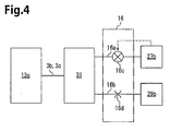
- a compressor of the second embodiment includes a control mechanism 16 shown in Fig. 4 instead of the control mechanism 15 used in the compressor of the first embodiment.
- the control mechanism 16 includes a bleed passage 16a, a gas supplying passage 16b, a control valve 16c, and an orifice 16d.
- the bleed passage 16a and the gas supplying passage 16b form a control passage.
- the bleed passage 16a is connected to the pressure regulation chamber 31 and the second suction chamber 27b.
- the gas supplying passage 16b is connected to the pressure regulation chamber 31 and the second discharge chamber 29b.
- the gas supplying passage 16b includes the orifice 16d.
- the control valve 16c is arranged in the bleed passage 16a.
- the control valve 16c adjusts the open degree of the bleed passage 16a based on the pressure of the second suction chamber 27b.
- a known valve may be used as the control valve 16c.
- the axial passage 3b and the radial passage 3c form portions of the bleed passage 16a and the gas supplying passage 16b.
- Other portions of the compressor have the same structure as the compressor of the first embodiment. Same reference numerals are given to those components that are the same as the corresponding components of the first embodiment. Such components will not be described in detail.
- control mechanism 16 of the compressor when the control valve 16c decreases the open degree of the bleed passage 16a, the pressure of the control pressure chamber 13c becomes substantially equal to the pressure of the second discharge chamber 29b.
- the movable body 13b of the actuator 13 moves toward the front against the centrifugal force and the compression reaction acting on the rotation members. This expands the control pressure chamber 13c and the movable body 13b pulls the bottom region of the swash plate 5 to increase the inclination angle of the swash plate 5.
- the inclination angle of the swash plate 5 increases in the compressor and lengthens the stroke of the pistons 9. This increases the compressor displacement for each rotation of the drive shaft 3 (refer to Fig. 1 ).
- control valve 16c allows for adjustment of the open degree of the bleed passage 16a.
- the low pressure of the second suction chamber 27b gradually decreases the pressure of the control pressure chamber 13c to a low value so that a suitable driving feel of the vehicle is maintained. Otherwise, the operation of the compressor is the same as the compressor of the first embodiment.
- a compressor of the third embodiment includes a housing 10 and pistons 90 instead of the housing 1 and the pistons 9 used in the compressor of the first embodiment.
- the housing 10 includes a front housing member 18, a rear housing member 19 similar to that of the first embodiment, and a second cylinder block 23 similar to that of the first embodiment.
- the front housing member 18 includes a boss 18a, which extends toward the front, and a recess 18b.
- a sealing device 25 is arranged in the boss 18a.
- the front housing member 18 differs from the front housing member 17 of the first embodiment in that the front housing member 18 does not include the first suction chamber 27a and the first discharge chamber 29a.
- a swash plate chamber 33 is defined in the front housing member 18 and the second cylinder block 23.
- the swash plate chamber 33 which is located in the middle portion of the housing 10, is in communication with the second suction chamber 27b through a second suction passage 37b.
- a first thrust bearing 35a is arranged in a recess 18b of the front housing member 18.
- the pistons 90 differ from the pistons 9 of the first embodiment in that each piston includes only one piston head 9b, which is formed on the rear end. Otherwise, the structure of the piston 90 and the compressor is the same as the first embodiment.
- the second cylinder bores 23a, the second compression chambers 23d, the second suction chamber 27b, and the second discharge chamber 29b will be referred to as the cylinder bores 23a, the compression chambers 23d, the suction chamber 27b, and the discharge chamber 29b, respectively.
- the rotation of the drive shaft 3 rotates the swash plate 5 and reciprocates the pistons 90 in the corresponding cylinder bores 23a.
- the volume of the compression chambers 23d changes in accordance with the piston stroke.
- Refrigerant gas from the evaporator is drawn through the suction port 330 into the swash plate chamber 33.
- the refrigerant gas is then drawn through the suction chamber 27b, compressed in each compression chamber 23d, and discharged into the discharge chamber 29b. Then, the refrigerant gas is discharged out of the discharge chamber 29b from a discharge port (not shown) toward the evaporator.
- the compressor changes the inclination angle of the swash plate 5 to control the compressor displacement by lengthening and shortening the stroke of the pistons 90.
- the inclination angle of the swash plate 5 decreases and shortens the stroke of the pistons 90. This decreases the compression displacement for each rotation of the drive shaft 3.
- the inclination angle of the swash plate 5 shown in Fig. 6 is the minimum inclination angle of the compressor.
- the compressor does not include the first cylinder block 21 and the like. This simplifies the structure in comparison with the compressor of the first embodiment. Thus, the compressor may be further reduced in size. Other advantages of the compressor are the same as the compressor of the first embodiment.
- a compressor of the fourth embodiment includes the control mechanism 16 of Fig. 4 in the compressor of the third embodiment.
- the advantages of the compressor are the same as the second and third embodiments.
- refrigerant gas is drawn into the first and second suction chambers 27a and 27b through the swash plate chamber 33.
- refrigerant gas may be directly drawn into the first and second suction chambers 27a and 27b from a pipe through a suction port.
- the first and second suction chambers 27a and 27b are in communication with the swash plate chamber 33 in the compressor, and the swash plate chamber 33 is configured to serve as a low pressure chamber.
- the pressure regulation chamber 31 may be omitted from the compressors of the first to fourth embodiments.
- a variable displacement swash compressor includes a housing, a drive shaft, a swash plate, a link mechanism, a piston, a conversion mechanism, an actuator, and a control mechanism.
- the swash plate is rotatable together with the drive shaft in a swash plate chamber.
- the conversion mechanism reciprocates the piston in a cylinder bore.
- the actuator changes the inclination angle of the swash plate.
- the actuator is rotatable integrally with the drive shaft.
- the actuator includes a partitioning body, a movable body, and a control pressure chamber.
- the control mechanism changes the pressure of the control pressure chamber to move the movable body.
- the movable body is adapted to pull the swash plate and increase the inclination angle when the pressure of the control pressure chamber increases.
Landscapes
- Engineering & Computer Science (AREA)
- Mechanical Engineering (AREA)
- General Engineering & Computer Science (AREA)
- Manufacturing & Machinery (AREA)
- Compressors, Vaccum Pumps And Other Relevant Systems (AREA)
- Reciprocating Pumps (AREA)
Applications Claiming Priority (1)
| Application Number | Priority Date | Filing Date | Title |
|---|---|---|---|
| JP2014070173A JP6194837B2 (ja) | 2014-03-28 | 2014-03-28 | 容量可変型斜板式圧縮機 |
Publications (2)
| Publication Number | Publication Date |
|---|---|
| EP2927493A2 true EP2927493A2 (fr) | 2015-10-07 |
| EP2927493A3 EP2927493A3 (fr) | 2015-12-02 |
Family
ID=52736909
Family Applications (1)
| Application Number | Title | Priority Date | Filing Date |
|---|---|---|---|
| EP15160828.8A Withdrawn EP2927493A3 (fr) | 2014-03-28 | 2015-03-25 | Compresseur à plateau oscillant à déplacement variable |
Country Status (5)
| Country | Link |
|---|---|
| US (1) | US9709045B2 (fr) |
| EP (1) | EP2927493A3 (fr) |
| JP (1) | JP6194837B2 (fr) |
| KR (1) | KR101735176B1 (fr) |
| CN (1) | CN104948412B (fr) |
Families Citing this family (4)
| Publication number | Priority date | Publication date | Assignee | Title |
|---|---|---|---|---|
| US20160069334A1 (en) * | 2013-03-29 | 2016-03-10 | Kabushiki Kaisha Toyota Jidoshokki | Variable displacement swash plate type compressor |
| JP2016151188A (ja) * | 2015-02-16 | 2016-08-22 | 株式会社豊田自動織機 | 容量可変型斜板式圧縮機 |
| KR102654623B1 (ko) * | 2021-12-15 | 2024-04-04 | (주)플로우테크 | 고품질의 그래핀을 대량으로 제조하는 방법 |
| KR102881686B1 (ko) * | 2023-06-12 | 2025-11-06 | (주)플로우테크 | 고품질의 그래핀을 대량으로 제조하는 방법 |
Citations (2)
| Publication number | Priority date | Publication date | Assignee | Title |
|---|---|---|---|---|
| JPS52131204A (en) | 1976-04-23 | 1977-11-04 | Borg Warner | Controllers for variable discharge compressors |
| JPH05172052A (ja) | 1991-12-18 | 1993-07-09 | Sanden Corp | 可変容量斜板式圧縮機 |
Family Cites Families (48)
| Publication number | Priority date | Publication date | Assignee | Title |
|---|---|---|---|---|
| US4061443A (en) | 1976-12-02 | 1977-12-06 | General Motors Corporation | Variable stroke compressor |
| US4108577A (en) * | 1977-06-09 | 1978-08-22 | General Motors Corporation | Variable displacement compressor |
| US4174191A (en) | 1978-01-18 | 1979-11-13 | Borg-Warner Corporation | Variable capacity compressor |
| US4606705A (en) | 1985-08-02 | 1986-08-19 | General Motors Corporation | Variable displacement compressor control valve arrangement |
| JPS62225782A (ja) * | 1986-03-27 | 1987-10-03 | Nippon Denso Co Ltd | 可変容量型揺動板式圧縮機 |
| JPS62247184A (ja) | 1986-04-18 | 1987-10-28 | Nippon Radiator Co Ltd | 容量可変斜板式コンプレツサ |
| JPS6477771A (en) | 1987-09-18 | 1989-03-23 | Hitachi Ltd | Variable delivery compressor |
| US4963074A (en) | 1988-01-08 | 1990-10-16 | Nippondenso Co., Ltd. | Variable displacement swash-plate type compressor |
| JP2503569B2 (ja) | 1988-02-24 | 1996-06-05 | 株式会社豊田自動織機製作所 | ワブル型コンプレッサの駆動制御装置 |
| JP2600305B2 (ja) | 1988-07-05 | 1997-04-16 | 株式会社豊田自動織機製作所 | 可変容量型斜板式圧縮機 |
| JPH07111171B2 (ja) | 1989-11-02 | 1995-11-29 | 株式会社豊田自動織機製作所 | 連続可変容量型斜板式圧縮機 |
| JP2532406Y2 (ja) | 1991-05-09 | 1997-04-16 | 株式会社豊田自動織機製作所 | 圧縮機のリテーナ一体ガスケット |
| JPH0518355A (ja) * | 1991-07-15 | 1993-01-26 | Toyota Autom Loom Works Ltd | 可変容量型圧縮機 |
| JPH05312144A (ja) | 1992-05-08 | 1993-11-22 | Sanden Corp | 可変容量斜板式圧縮機 |
| JP2932952B2 (ja) | 1994-12-07 | 1999-08-09 | 株式会社豊田自動織機製作所 | クラッチレス可変容量型圧縮機 |
| JP3175536B2 (ja) * | 1995-06-13 | 2001-06-11 | 株式会社豊田自動織機製作所 | クラッチレス可変容量型圧縮機における容量制御構造 |
| KR100203975B1 (ko) | 1995-10-26 | 1999-06-15 | 이소가이 치세이 | 캠 플레이트식 가변용량 압축기 |
| JPH102284A (ja) | 1996-06-17 | 1998-01-06 | Toyota Autom Loom Works Ltd | 可変容量圧縮機及びその制御方法 |
| JPH1054349A (ja) | 1996-08-12 | 1998-02-24 | Toyota Autom Loom Works Ltd | 可変容量圧縮機 |
| US6077047A (en) | 1997-01-24 | 2000-06-20 | Kabushiki Kaisha Toyoda Jidoshokki Seisakusho | Variable displacement compressor |
| JPH10246181A (ja) | 1997-02-28 | 1998-09-14 | Toyota Autom Loom Works Ltd | 可変容量型圧縮機 |
| JP3582284B2 (ja) | 1997-03-13 | 2004-10-27 | 株式会社豊田自動織機 | 冷凍回路及び圧縮機 |
| JP4007637B2 (ja) | 1997-03-31 | 2007-11-14 | サンデン株式会社 | 可変容量圧縮機 |
| JPH11257217A (ja) | 1998-03-16 | 1999-09-21 | Toyota Autom Loom Works Ltd | 片側可変容量型圧縮機 |
| JP2000186668A (ja) | 1998-12-22 | 2000-07-04 | Toyota Autom Loom Works Ltd | 可変容量型圧縮機における容量制御構造 |
| DE19939131A1 (de) * | 1999-08-18 | 2001-03-08 | Zexel Gmbh | Axialkolbentriebwerk mit einem stufenlos verstellbaren Kolbenhub |
| JP2001063353A (ja) | 1999-08-24 | 2001-03-13 | Toyota Autom Loom Works Ltd | 可変容量型圧縮機の制御装置 |
| JP2001107849A (ja) | 1999-10-08 | 2001-04-17 | Toyota Autom Loom Works Ltd | 可変容量型圧縮機 |
| JP3933369B2 (ja) | 2000-04-04 | 2007-06-20 | サンデン株式会社 | ピストン式可変容量圧縮機 |
| JP2002031050A (ja) | 2000-07-17 | 2002-01-31 | Toyota Industries Corp | 圧縮機 |
| WO2002061280A1 (fr) | 2001-01-29 | 2002-08-08 | Zexel Valeo Climate Control Corporation | Compresseur sans embrayage a came plate a cylindree variable |
| JP4023351B2 (ja) | 2002-05-29 | 2007-12-19 | 株式会社デンソー | 揺動斜板型可変容量式圧縮機 |
| JP2004060644A (ja) | 2002-06-05 | 2004-02-26 | Denso Corp | 圧縮機装置およびその制御方法 |
| JP4378190B2 (ja) | 2004-02-25 | 2009-12-02 | 株式会社ミクニ | プランジャ式流体吐出装置 |
| JP2006022785A (ja) | 2004-07-09 | 2006-01-26 | Toyota Industries Corp | 容量可変型圧縮機 |
| JP4330576B2 (ja) | 2005-10-28 | 2009-09-16 | サンデン株式会社 | 圧縮機 |
| JP2008045523A (ja) | 2006-08-21 | 2008-02-28 | Toyota Industries Corp | 可変容量型圧縮機における容量制御構造 |
| US20090107327A1 (en) | 2007-10-03 | 2009-04-30 | Masaki Ota | Capacity-variable type swash plate compressor |
| JP6003546B2 (ja) | 2012-11-05 | 2016-10-05 | 株式会社豊田自動織機 | 容量可変型斜板式圧縮機 |
| JP6028524B2 (ja) * | 2012-11-05 | 2016-11-16 | 株式会社豊田自動織機 | 容量可変型斜板式圧縮機 |
| JP6028525B2 (ja) | 2012-11-05 | 2016-11-16 | 株式会社豊田自動織機 | 容量可変型斜板式圧縮機 |
| WO2014069618A1 (fr) | 2012-11-05 | 2014-05-08 | 株式会社 豊田自動織機 | Compresseur à plateau en biais à déplacement variable |
| JP6003547B2 (ja) | 2012-11-05 | 2016-10-05 | 株式会社豊田自動織機 | 容量可変型斜板式圧縮機 |
| JP5870902B2 (ja) | 2012-11-05 | 2016-03-01 | 株式会社豊田自動織機 | 容量可変型斜板式圧縮機 |
| JP6083291B2 (ja) | 2013-03-27 | 2017-02-22 | 株式会社豊田自動織機 | 容量可変型斜板式圧縮機 |
| JP6032098B2 (ja) | 2013-03-29 | 2016-11-24 | 株式会社豊田自動織機 | 容量可変型斜板式圧縮機 |
| JP6115258B2 (ja) | 2013-03-29 | 2017-04-19 | 株式会社豊田自動織機 | 両頭ピストン型斜板式圧縮機 |
| JP2015183615A (ja) | 2014-03-25 | 2015-10-22 | 株式会社豊田自動織機 | 可変容量型斜板式圧縮機 |
-
2014
- 2014-03-28 JP JP2014070173A patent/JP6194837B2/ja not_active Expired - Fee Related
-
2015
- 2015-03-24 US US14/666,688 patent/US9709045B2/en not_active Expired - Fee Related
- 2015-03-24 KR KR1020150040837A patent/KR101735176B1/ko not_active Expired - Fee Related
- 2015-03-25 CN CN201510133584.4A patent/CN104948412B/zh not_active Expired - Fee Related
- 2015-03-25 EP EP15160828.8A patent/EP2927493A3/fr not_active Withdrawn
Patent Citations (2)
| Publication number | Priority date | Publication date | Assignee | Title |
|---|---|---|---|---|
| JPS52131204A (en) | 1976-04-23 | 1977-11-04 | Borg Warner | Controllers for variable discharge compressors |
| JPH05172052A (ja) | 1991-12-18 | 1993-07-09 | Sanden Corp | 可変容量斜板式圧縮機 |
Also Published As
| Publication number | Publication date |
|---|---|
| US9709045B2 (en) | 2017-07-18 |
| EP2927493A3 (fr) | 2015-12-02 |
| JP6194837B2 (ja) | 2017-09-13 |
| KR20150112841A (ko) | 2015-10-07 |
| US20150275873A1 (en) | 2015-10-01 |
| CN104948412A (zh) | 2015-09-30 |
| JP2015190432A (ja) | 2015-11-02 |
| CN104948412B (zh) | 2017-04-05 |
| KR101735176B1 (ko) | 2017-05-12 |
Similar Documents
| Publication | Publication Date | Title |
|---|---|---|
| EP2728182A2 (fr) | Compresseur à déplacement variable de type plateau oscillant | |
| EP2728184A2 (fr) | Compresseur à déplacement variable de type plateau oscillant | |
| EP2728183A2 (fr) | Compresseur à déplacement variable de type plateau oscillant | |
| EP2784316A1 (fr) | Compresseur à plateau oscillant à déplacement variable | |
| EP2728185A2 (fr) | Compresseur à déplacement variable de type plateau oscillant | |
| US9903352B2 (en) | Swash plate type variable displacement compressor | |
| EP2927493A2 (fr) | Compresseur à plateau oscillant à déplacement variable | |
| EP2784318B1 (fr) | Compresseur à plateau oscillant à déplacement variable | |
| US9915252B2 (en) | Variable displacement swash plate compressor having a fulcrum and an action point located on opposite sides of a drive shaft | |
| US9903354B2 (en) | Variable displacement swash plate compressor | |
| CN104948416B (zh) | 可变排量旋转斜板式压缩机 | |
| EP2944814A2 (fr) | Compresseur à plateau oscillant à déplacement variable | |
| US9903353B2 (en) | Variable displacement swash plate compressor | |
| JP6032228B2 (ja) | 容量可変型斜板式圧縮機 |
Legal Events
| Date | Code | Title | Description |
|---|---|---|---|
| PUAI | Public reference made under article 153(3) epc to a published international application that has entered the european phase |
Free format text: ORIGINAL CODE: 0009012 |
|
| 17P | Request for examination filed |
Effective date: 20150325 |
|
| AK | Designated contracting states |
Kind code of ref document: A2 Designated state(s): AL AT BE BG CH CY CZ DE DK EE ES FI FR GB GR HR HU IE IS IT LI LT LU LV MC MK MT NL NO PL PT RO RS SE SI SK SM TR |
|
| AX | Request for extension of the european patent |
Extension state: BA ME |
|
| PUAL | Search report despatched |
Free format text: ORIGINAL CODE: 0009013 |
|
| AK | Designated contracting states |
Kind code of ref document: A3 Designated state(s): AL AT BE BG CH CY CZ DE DK EE ES FI FR GB GR HR HU IE IS IT LI LT LU LV MC MK MT NL NO PL PT RO RS SE SI SK SM TR |
|
| AX | Request for extension of the european patent |
Extension state: BA ME |
|
| RIC1 | Information provided on ipc code assigned before grant |
Ipc: F04B 27/10 20060101AFI20151029BHEP Ipc: F04B 27/18 20060101ALI20151029BHEP |
|
| STAA | Information on the status of an ep patent application or granted ep patent |
Free format text: STATUS: THE APPLICATION HAS BEEN WITHDRAWN |
|
| 18W | Application withdrawn |
Effective date: 20180220 |