EP2930004A1 - Dispositif d'ensemble évent pour extrudeuse à double vis - Google Patents
Dispositif d'ensemble évent pour extrudeuse à double vis Download PDFInfo
- Publication number
- EP2930004A1 EP2930004A1 EP14754908.3A EP14754908A EP2930004A1 EP 2930004 A1 EP2930004 A1 EP 2930004A1 EP 14754908 A EP14754908 A EP 14754908A EP 2930004 A1 EP2930004 A1 EP 2930004A1
- Authority
- EP
- European Patent Office
- Prior art keywords
- vent assembly
- vent
- units
- screw
- twin
- Prior art date
- Legal status (The legal status is an assumption and is not a legal conclusion. Google has not performed a legal analysis and makes no representation as to the accuracy of the status listed.)
- Granted
Links
Images


Classifications
-
- B—PERFORMING OPERATIONS; TRANSPORTING
- B29—WORKING OF PLASTICS; WORKING OF SUBSTANCES IN A PLASTIC STATE IN GENERAL
- B29C—SHAPING OR JOINING OF PLASTICS; SHAPING OF MATERIAL IN A PLASTIC STATE, NOT OTHERWISE PROVIDED FOR; AFTER-TREATMENT OF THE SHAPED PRODUCTS, e.g. REPAIRING
- B29C48/00—Extrusion moulding, i.e. expressing the moulding material through a die or nozzle which imparts the desired form; Apparatus therefor
- B29C48/25—Component parts, details or accessories; Auxiliary operations
- B29C48/36—Means for plasticising or homogenising the moulding material or forcing it through the nozzle or die
- B29C48/50—Details of extruders
- B29C48/76—Venting, drying means; Degassing means
- B29C48/763—Vent constructions, e.g. venting means avoiding melt escape
-
- B—PERFORMING OPERATIONS; TRANSPORTING
- B29—WORKING OF PLASTICS; WORKING OF SUBSTANCES IN A PLASTIC STATE IN GENERAL
- B29C—SHAPING OR JOINING OF PLASTICS; SHAPING OF MATERIAL IN A PLASTIC STATE, NOT OTHERWISE PROVIDED FOR; AFTER-TREATMENT OF THE SHAPED PRODUCTS, e.g. REPAIRING
- B29C48/00—Extrusion moulding, i.e. expressing the moulding material through a die or nozzle which imparts the desired form; Apparatus therefor
- B29C48/25—Component parts, details or accessories; Auxiliary operations
- B29C48/256—Exchangeable extruder parts
- B29C48/2568—Inserts
- B29C48/25684—Inserts for barrels
-
- B—PERFORMING OPERATIONS; TRANSPORTING
- B29—WORKING OF PLASTICS; WORKING OF SUBSTANCES IN A PLASTIC STATE IN GENERAL
- B29C—SHAPING OR JOINING OF PLASTICS; SHAPING OF MATERIAL IN A PLASTIC STATE, NOT OTHERWISE PROVIDED FOR; AFTER-TREATMENT OF THE SHAPED PRODUCTS, e.g. REPAIRING
- B29C48/00—Extrusion moulding, i.e. expressing the moulding material through a die or nozzle which imparts the desired form; Apparatus therefor
- B29C48/25—Component parts, details or accessories; Auxiliary operations
- B29C48/36—Means for plasticising or homogenising the moulding material or forcing it through the nozzle or die
- B29C48/395—Means for plasticising or homogenising the moulding material or forcing it through the nozzle or die using screws surrounded by a cooperating barrel, e.g. single screw extruders
- B29C48/40—Means for plasticising or homogenising the moulding material or forcing it through the nozzle or die using screws surrounded by a cooperating barrel, e.g. single screw extruders using two or more parallel screws or at least two parallel non-intermeshing screws, e.g. twin screw extruders
- B29C48/402—Means for plasticising or homogenising the moulding material or forcing it through the nozzle or die using screws surrounded by a cooperating barrel, e.g. single screw extruders using two or more parallel screws or at least two parallel non-intermeshing screws, e.g. twin screw extruders the screws having intermeshing parts
-
- B—PERFORMING OPERATIONS; TRANSPORTING
- B29—WORKING OF PLASTICS; WORKING OF SUBSTANCES IN A PLASTIC STATE IN GENERAL
- B29C—SHAPING OR JOINING OF PLASTICS; SHAPING OF MATERIAL IN A PLASTIC STATE, NOT OTHERWISE PROVIDED FOR; AFTER-TREATMENT OF THE SHAPED PRODUCTS, e.g. REPAIRING
- B29C48/00—Extrusion moulding, i.e. expressing the moulding material through a die or nozzle which imparts the desired form; Apparatus therefor
- B29C48/25—Component parts, details or accessories; Auxiliary operations
- B29C48/36—Means for plasticising or homogenising the moulding material or forcing it through the nozzle or die
- B29C48/395—Means for plasticising or homogenising the moulding material or forcing it through the nozzle or die using screws surrounded by a cooperating barrel, e.g. single screw extruders
- B29C48/40—Means for plasticising or homogenising the moulding material or forcing it through the nozzle or die using screws surrounded by a cooperating barrel, e.g. single screw extruders using two or more parallel screws or at least two parallel non-intermeshing screws, e.g. twin screw extruders
- B29C48/405—Intermeshing co-rotating screws
-
- B—PERFORMING OPERATIONS; TRANSPORTING
- B29—WORKING OF PLASTICS; WORKING OF SUBSTANCES IN A PLASTIC STATE IN GENERAL
- B29C—SHAPING OR JOINING OF PLASTICS; SHAPING OF MATERIAL IN A PLASTIC STATE, NOT OTHERWISE PROVIDED FOR; AFTER-TREATMENT OF THE SHAPED PRODUCTS, e.g. REPAIRING
- B29C48/00—Extrusion moulding, i.e. expressing the moulding material through a die or nozzle which imparts the desired form; Apparatus therefor
- B29C48/25—Component parts, details or accessories; Auxiliary operations
- B29C48/36—Means for plasticising or homogenising the moulding material or forcing it through the nozzle or die
- B29C48/50—Details of extruders
- B29C48/76—Venting, drying means; Degassing means
- B29C48/765—Venting, drying means; Degassing means in the extruder apparatus
- B29C48/766—Venting, drying means; Degassing means in the extruder apparatus in screw extruders
- B29C48/767—Venting, drying means; Degassing means in the extruder apparatus in screw extruders through a degassing opening of a barrel
Definitions
- the present invention relates to a vent assembly device for a twin-screw extruder, and more particularly to a novel improvement for making it possible to freely modify the size of a vent opening in a vent assembly, by forming the vent assembly device from a plurality of small pieces of vent assembly units.
- vent assembly devices for twin-screw extruders include, for instance, the configuration disclosed in Patent literature 1, illustrated in Fig. 13 .
- the reference symbol 7 denotes a vent assembly that is provided on a cylinder 1 of a twin-screw extruder 11.
- the whole vent assembly 7 is formed integrally so as to have a deaeration port 6.
- a first screw 2 and a second screw 3 are rotatably provided, meshing with each other, in respective screw receiving holes 4, 5 within the cylinder 1.
- An undercut 8 of the vent assembly 7 is configured so as to cover part of the first and second screws 2, 3.
- Patent literature 1 Japanese Patent Application Publication No. 2004-25669
- vent assembly structure of the twin-screw extruder must selectively utilize various types of vent assembly, such as those illustrated in Fig. 14 to Fig. 16 , depending on the viscosity, flowability and degree of adhesion of a starting material, and the volatile content generated by the starting material.
- various types of vent assembly such as those illustrated in Fig. 14 to Fig. 16 , depending on the viscosity, flowability and degree of adhesion of a starting material, and the volatile content generated by the starting material.
- substantial volatile matter content in the starting material, or substantial content of volatile matter used as a devolatilizing agent reducing the flow rate of gas at vent ports allows preventing vent rise and scattering of resin fragments (entrainment).
- an A-type having a large vent port opening of Fig. 14 is suitable herein, with high resin viscosity and no wrapping around the screws
- a C-type of Fig. 16 having a restraint on the left axis-side is suitably used for a starting material that exhibits
- vent assembly device in Fig. 14 by contrast, a vent assembly was proposed that could cope with a given specific starting material; to produce small runs of numerous article types, however, it was necessary to fabricate an optimal vent assembly device, and check the operation of the latter, depending on the viscosity, flowability, degree of adhesion and generated volatile content of the starting material whenever the starting material was changed.
- a starting material that required fine adjustments for vent rise it was necessary to fabricate a large number of vent assemblies, and to assess an optimal vent assembly for each given starting material, all of which entailed considerable expense.
- vent assemblies optimized for each starting material In the production of small runs of numerous article types as well, it was necessary to possess vent assemblies optimized for each starting material, and significant equipment costs were accordingly incurred. Preparing numerous types of vent assembly translated into necessary space for storage and storage costs, and was thus undesirable in terms of management of the twin-screw extruder.
- the present invention arrived at in order to solve such problems, resorts in particular, to a configuration wherein the size of at least a vent opening of a vent assembly can be modified freely by forming the vent assembly from a plurality of vent assembly units that are formed by dividing up the vent assembly into small pieces.
- the vent assembly device for a twin-screw extruder is a vent assembly device for a twin-screw extruder, including a vent assembly that has a vent opening and that is provided in a cylinder of a twin-screw extruder having a left axis-side screw and a right axis-side screw, wherein the size of at least the vent opening of the vent assembly can be modified freely by forming the vent assembly from a plurality of vent assembly units.
- vent assembly units corresponding to the left axis-side screw are formed of a plurality of units
- the vent assembly units corresponding to the right axis-side screw are formed of a plurality of units
- the vent assembly units have a linear shape and an L-shape as viewed in a cross-section.
- the vent assembly units corresponding to the left axis-side screw are formed of one or a plurality of units
- the vent assembly units corresponding to the right axis-side screw are formed of one or a plurality of units
- the vent assembly units have a linear shape and an L-shape as viewed in a transverse cross-section.
- Each vent assembly unit is clamped by a clamping screw configured such that a longitudinal direction thereof is disposed to be parallel to a horizontal line that joins a left axial center of the left axis-side screw and a right axial center of the right axis-side screw.
- the vent assembly units that are positioned on both outermost sides, as viewed from a cross-section of the vent assembly, have an L-shape as viewed in a cross-section.
- the vent assembly units all have an L-shaped cross-section, such that a top piece that is formed at the top of each of the vent assembly units extends in a horizontal direction, and a fixing screw is screwed in each top piece along a vertical direction.
- vent assembly device for a twin-screw extruder affords the following effects.
- a vent assembly device for a twin-screw extruder including a vent assembly that has a vent opening and that is provided in a cylinder of a twin-screw extruder having a left axis-side screw and a right axis-side screw, the size of at least the vent opening of the vent assembly can be modified freely by forming the vent assembly from a plurality of vent assembly units.
- vent shape can be easily modified on the basis of combinations of vent assembly units, even if the characteristics of the starting material varies, while no new vent assembly need be fabricated afresh. Costs can be accordingly reduced.
- vent shape can be easily modified on the basis of combinations of vent assembly units, even if the characteristics of the starting material varies, while no new vent assembly need be fabricated afresh.
- Maintenance costs can be reduced in that it becomes possible to replace just those problematic vent assembly units in case of occurrence of partial corrosion, derived from a corrosive component contained in the starting material, or partial wear of edges or the like.
- vent rise vent rise
- vent wall adhesion scattering of resin fragments (entrainment) and the like, derived from differences in, for instance, the viscosity, flowability, degree of adhesion and generated volatile content of a starting material, can be forestalled by using the vent assembly of the present invention.
- vent assembly units corresponding to the left axis-side screw are formed of a plurality of units
- the vent assembly units corresponding to the right axis-side screw are formed of a plurality of units
- the vent assembly units have a linear shape and an L-shape as viewed in a cross-section.
- the special vent shape corresponds roughly to an undercut on either one of the left axis-side screw or right axis-side screw (side of upward rotation at a meshing section). Accordingly, it suffices to prepare beforehand, or fabricate anew, a plurality of sets of vent assembly units for this screw alone.
- vent assembly units corresponding to the left axis-side screw are formed of one or a plurality of units
- the vent assembly units corresponding to the right axis-side screw are formed of one or a plurality of units
- the vent assembly units have a linear shape and an L-shape as viewed in a transverse cross-section. Vent assemblies can be fabricated easily as a result.
- Each vent assembly unit is clamped by a clamping screw configured such that a longitudinal direction thereof is disposed to be parallel to a horizontal line that joins a left axial center of the left axis-side screw and a right axial center of the right axis-side screw.
- the vent assembly can be assembled easily as a result.
- the vent assembly units that are positioned on both outermost sides, as viewed from a cross-section of the vent assembly, have an L-shape as viewed in a cross-section. As a result, the vent assembly units are fabricated very easily.
- the vent assembly units all have an L-shaped cross-section, such that a top piece that is formed at the top of each of the vent assembly units extends in a horizontal direction, and a fixing screw is screwed in each top piece along a vertical direction.
- the reference symbol 1 denotes a cylinder the overall shape thereof is that of a long tube, such that a pair of screw receiving holes 4, 5 is formed within the cylinder 1.
- the screw receiving holes 4, 5 there are respectively provided a left axis-side screw 2 and a right axis-side screw 3, so as to be rotatable along a same direction denoted by the arrows, in a state where the left axis-side screw 2 and the right axis-side screw 3 mesh with each other.
- a vent assembly 7 having a vent opening 6 is provided inside the vent receiving hole 10 that is formed within the cylinder 1.
- the vent assembly 7 is configured by a plurality of vent assembly units 7a.
- the vent assembly 7, which is illustrated as a longitudinal section, is configured by two types of vent assembly, including a vent assembly made up of a plurality of linear shapes, viewed in a longitudinal section, and a plurality of L-shapes having respective top pieces 7aA that extend in a horizontal direction and that that have a flange shape.
- the vent assembly units 7a are depicted in a state in which there is formed a vent opening 6 in the smallest state (small transversal width W) as viewed in a cross-section.
- the forms depicted in Fig. 2 to Fig. 6 below are instances where, in the configuration of Fig. 1 , the vent assembly units 7a are integrated using respective clamping screws 12 and the number of the vent assembly units 7a, corresponding to the screws 2, 3, is modified, to freely modify thereby the size (transversal width W as viewed in a cross-section) of the vent opening 6.
- vent assembly units 7a corresponding to the left axis-side screw 2
- vent assembly units 7a corresponding to the right axis-side screw 3
- a small vent opening 6 i.e. an assembly in a state where the transversal width W is small, as viewed in a cross-section.
- Each vent assembly unit 7a is clamped in a state where there is screwed a clamping screw 12 configured such that the longitudinal direction A thereof is disposed to be parallel to a horizontal line 13 that joins a left axial center P 1 and a right axial center P 2 of the respective screws 2, 3.
- the size (transversal width W) of the vent opening 6 is increased, with respect to the configuration of Fig. 2 , through a reduction in the number of the vent assembly units 7a corresponding to the right axis-side screw 3, such that the left axis-side restraint is now large, the right axis-side restraint is medium, and the size (transversal width W) of the vent opening 6 is medium.
- Fig. 4 the number of the vent assembly units 7a corresponding to the right axis-side screw 3 in Fig. 3 is reduced to only one L-shaped vent assembly unit; a state is thus brought about in which the left axis-side restraint is large, the right axis-side restraint is small, and the vent opening 6 is wide.
- the number of the vent assembly units 7a corresponding to the right axis-side screw 3 is identical to that of Fig. 2 , while the number of the vent assembly units 7a corresponding to the left axis-side screw 2 is reduced with respect to that of Fig. 2 , such that the transversal width W is greater than that of the vent opening 6 of fig. 1 , the left axis-side restraint is medium, the right axis-side restraint is large and the size of the vent opening 6 is medium.
- the configuration in Fig. 6 is the exact opposite of the configuration of Fig. 4 described above, with one vent assembly unit 7a corresponding to the left axis-side screw 2 and the number of the vent assembly units 7a corresponding to the right axis-side screw 3 set to be identical to that of the configuration of Fig. 2 ; as a result, the left axis-side restraint is small, the right axis-side restraint is large, the size of the vent opening 6 is large, and the left-right position of the vent opening 6 in Fig. 4 is the reverse of that of Fig. 6 .
- the size and position of the vent opening 6 with respect to the screws 2, 3 can be modified freely when the size and the position of the vent opening 6 are modified in a case where the characteristic of the starting material changes, and when only a vent assembly unit 7a at a problematic location is replaced, in case of occurrence of partial corrosion, derived from a corrosive component contained in the starting material, or partial wear of edges or the like, and it becomes possible to dispense with the hassle of fabricating beforehand the vent assembly 7 every time, of fabricating beforehand multiple types of the vent assembly 7, as in conventional instances.
- the vent assembly units 7a that are positioned on both outermost sides, as viewed in a cross-section have an L-shape.
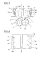
- Fig. 7 and Fig. 9 illustrate another form, different from those illustrated in Fig. 1 through Fig. 6 above.
- the vent assembly units 7a all have an L-shaped cross-section, such that at the top of the vent assembly units 7a there are formed respective top pieces 7aA that extend in the horizontal direction.
- the top pieces 7aA are fixed to each other, or to the cylinder 1, by respective fixing screws 15 that are screwed in a direction perpendicular to the horizontal line 13, i.e. in the vertical direction, via through-holes 7B that have an inner diameter larger than the outer diameter of the fixing screws 15.
- the top pieces 7aA may be staggered with respect to each other, as illustrated in Fig. 8 , or may be disposed along a straight line, as illustrated in Fig. 10 .
- Each fixing screw 15 is configured as illustrated in Fig. 9 with through-holes 7B having an inner diameter larger than the outer diameter of the fixing screws 15 being formed in the respective top pieces 7aA, such that the fixing screws 15 of the top pieces 7aA that are positioned below the uppermost top piece 7aA can be screwed-fastened and removed, at a time where respective top pieces 7aA overlap the top of the fixing screws 15.
- Fig. 11 and Fig. 12 illustrate another instance of the form illustrated in Fig. 1 through Fig. 6 above.
- a longitudinal groove 7aT and a longitudinal ridge 7aL are formed, along the vertical direction, in order to connect a respective L-shaped vent assembly unit 7a with a respective vent assembly unit 7a of linear shape.
- Each vent assembly unit 7a becomes integral with a respective longitudinal groove 7aT through fitting of the longitudinal ridge 7aL, whereupon a first and a second arc-shaped section 7aJ, 7aK become connected in a contiguous state.
- the above configuration further includes a circular eyehole 7aN formed in the top piece 7aA of each L-shaped vent assembly unit 7a, so that the fitting state of the longitudinal ridge 7aL with the longitudinal groove 7aT can be checked via the eyehole 7aN.
- Fig. 12 illustrates another form of Fig. 11 .
- all the vent assembly units 7a have a linear shape, and a plurality of transversal ridges 7aY is provided in one vent assembly unit 7a while transversal grooves 7aM into which the transversal ridges 7aY fit are formed in the other vent assembly unit 7a.
- a shape in which the first and the second arc-shaped sections 7aJ and 7aK are contiguous is thus achieved by combining the vent assembly units 7a.
- Fig. 11 and Fig. 12 illustrate a pair of vent assembly units 7a, but other combinations of one or more pairs can also be resorted to, as needed.
- the vent assembly device for a twin-screw extruder allows freely modifying the size of a vent opening of a vent assembly. This makes the vent assembly device for a twin-screw extruder suitable for, for instance, testing of novel extrusion processes.
Landscapes
- Engineering & Computer Science (AREA)
- Mechanical Engineering (AREA)
- Extrusion Moulding Of Plastics Or The Like (AREA)
Applications Claiming Priority (2)
| Application Number | Priority Date | Filing Date | Title |
|---|---|---|---|
| JP2013031974A JP5623568B2 (ja) | 2013-02-21 | 2013-02-21 | 二軸押出機用ベント金物装置 |
| PCT/JP2014/053256 WO2014129367A1 (fr) | 2013-02-21 | 2014-02-13 | Dispositif d'ensemble évent pour extrudeuse à double vis |
Publications (3)
| Publication Number | Publication Date |
|---|---|
| EP2930004A1 true EP2930004A1 (fr) | 2015-10-14 |
| EP2930004A4 EP2930004A4 (fr) | 2016-08-31 |
| EP2930004B1 EP2930004B1 (fr) | 2018-05-02 |
Family
ID=51391162
Family Applications (1)
| Application Number | Title | Priority Date | Filing Date |
|---|---|---|---|
| EP14754908.3A Active EP2930004B1 (fr) | 2013-02-21 | 2014-02-13 | Dispositif d'ensemble évent pour extrudeuse à double vis |
Country Status (5)
| Country | Link |
|---|---|
| US (1) | US9731448B2 (fr) |
| EP (1) | EP2930004B1 (fr) |
| JP (1) | JP5623568B2 (fr) |
| CN (1) | CN104995009B (fr) |
| WO (1) | WO2014129367A1 (fr) |
Cited By (1)
| Publication number | Priority date | Publication date | Assignee | Title |
|---|---|---|---|---|
| WO2025166393A1 (fr) * | 2024-02-09 | 2025-08-14 | 4Next Generation Gmbh | Dispositif de traitement de matières plastiques |
Families Citing this family (2)
| Publication number | Priority date | Publication date | Assignee | Title |
|---|---|---|---|---|
| JP6757507B2 (ja) * | 2016-01-22 | 2020-09-23 | 東レ株式会社 | 熱可塑性樹脂組成物の製造方法 |
| JP7307635B2 (ja) * | 2019-09-03 | 2023-07-12 | 株式会社日本製鋼所 | 二軸混練押出機及びベントアダプター |
Family Cites Families (12)
| Publication number | Priority date | Publication date | Assignee | Title |
|---|---|---|---|---|
| US2078565A (en) * | 1933-10-30 | 1937-04-27 | Durst Emanuel | Vacuum press and the like |
| US3917507A (en) * | 1971-02-22 | 1975-11-04 | Welding Engineers | Countercurrent combined liquid and vapor stripping in screw devolatilizer |
| JP2839353B2 (ja) * | 1990-10-22 | 1998-12-16 | 株式会社神戸製鋼所 | 二軸混練機のベント装置 |
| DE4228468A1 (de) * | 1992-08-27 | 1994-03-03 | Werner & Pfleiderer | Entgasungsvorrichtung für eine zweiwellige Schneckenmaschine zur Aufbereitung von Kunststoffen |
| DE19630383C1 (de) * | 1996-07-29 | 1997-09-18 | Christ Hubert Dr | Entgasungsvorrichtung an Extrudern |
| JP2001138381A (ja) * | 1999-11-12 | 2001-05-22 | Japan Steel Works Ltd:The | サイドベント装置 |
| JP3712185B2 (ja) * | 2001-01-17 | 2005-11-02 | 株式会社日本製鋼所 | 微粉原料供給装置 |
| JP2004025669A (ja) * | 2002-06-26 | 2004-01-29 | Japan Steel Works Ltd:The | 押出機用ベント金物装置および押出機 |
| CN2567025Y (zh) * | 2002-11-23 | 2003-08-20 | 汕头市奇佳机械厂有限公司 | 片材挤出机的排气装置 |
| EP2218568B1 (fr) | 2009-02-11 | 2012-01-18 | Coperion GmbH | Machine à vis sans fin |
| JP5467796B2 (ja) | 2009-04-24 | 2014-04-09 | 株式会社三和商会 | 押出機のベント装置、及び押出機による混練方法 |
| CN202129974U (zh) * | 2011-07-25 | 2012-02-01 | 浙江百纳橡塑设备有限公司 | 橡胶挤出机的排气装置 |
-
2013
- 2013-02-21 JP JP2013031974A patent/JP5623568B2/ja active Active
-
2014
- 2014-02-13 US US14/651,446 patent/US9731448B2/en active Active
- 2014-02-13 CN CN201480009359.3A patent/CN104995009B/zh active Active
- 2014-02-13 WO PCT/JP2014/053256 patent/WO2014129367A1/fr not_active Ceased
- 2014-02-13 EP EP14754908.3A patent/EP2930004B1/fr active Active
Cited By (1)
| Publication number | Priority date | Publication date | Assignee | Title |
|---|---|---|---|---|
| WO2025166393A1 (fr) * | 2024-02-09 | 2025-08-14 | 4Next Generation Gmbh | Dispositif de traitement de matières plastiques |
Also Published As
| Publication number | Publication date |
|---|---|
| US9731448B2 (en) | 2017-08-15 |
| EP2930004A4 (fr) | 2016-08-31 |
| JP5623568B2 (ja) | 2014-11-12 |
| US20150314512A1 (en) | 2015-11-05 |
| JP2014162013A (ja) | 2014-09-08 |
| EP2930004B1 (fr) | 2018-05-02 |
| WO2014129367A1 (fr) | 2014-08-28 |
| CN104995009A (zh) | 2015-10-21 |
| CN104995009B (zh) | 2017-05-24 |
Similar Documents
| Publication | Publication Date | Title |
|---|---|---|
| US11312041B2 (en) | Extruder mixing element | |
| US7981340B2 (en) | Method of degassing a flowable mass in a ring extruder | |
| EP2930004B1 (fr) | Dispositif d'ensemble évent pour extrudeuse à double vis | |
| JP2011524284A5 (fr) | ||
| DE102009019226A1 (de) | Anordnung mit Leuchtelementen zur Lichtabgabe | |
| WO2016185885A1 (fr) | Vis à billes | |
| CA2949392C (fr) | Outil de type moule pour le moulage par injection | |
| WO2015043888A1 (fr) | Corps d'usure pour recevoir une double vis pour l'extrusion d'une matière fusible | |
| WO2018079241A1 (fr) | Tête d'extrusion et dispositif d'extrusion | |
| US20250196077A1 (en) | Screw elements with improved mixing effect and pressure build-up | |
| CN105864289B (zh) | 一种组装式模组化导轨 | |
| CN103968023B (zh) | 具双螺帽预压结构的端盖式滚珠螺杆 | |
| EP2821196A1 (fr) | Paire de vis et extrudeuse à vis jumelées à engrenage co-rotatif prévu avec une paire de vis | |
| JP6759707B2 (ja) | スクリュー、押出機およびミキシングデバイス | |
| KR0125105B1 (ko) | 압출성형기의 실린더 | |
| CN221985777U (zh) | 一种装配式双金属衬套的双螺杆挤出机筒体 | |
| JP6772546B2 (ja) | スクリュー、押出機およびカラー | |
| CN211279902U (zh) | 分体式单螺杆挤出机 | |
| CN208664339U (zh) | 一种阻燃pc/abs合金料挤出结构 | |
| JP2002283434A (ja) | 混練リング及びスクリュ式混練押出機 | |
| ITUB20154130A1 (it) | Giunto per la trasmissione della coppia e gruppo di trasmissione della coppia comprendente tale giunto | |
| JP2005169889A (ja) | ブレーカープレート | |
| JP2007118519A (ja) | ブレーカープレートおよびそれを用いた押出成形機 | |
| CN113290821A (zh) | 双螺杆挤出机机头 | |
| UA12124U (en) | Single-worm extruder |
Legal Events
| Date | Code | Title | Description |
|---|---|---|---|
| PUAI | Public reference made under article 153(3) epc to a published international application that has entered the european phase |
Free format text: ORIGINAL CODE: 0009012 |
|
| 17P | Request for examination filed |
Effective date: 20150617 |
|
| AK | Designated contracting states |
Kind code of ref document: A1 Designated state(s): AL AT BE BG CH CY CZ DE DK EE ES FI FR GB GR HR HU IE IS IT LI LT LU LV MC MK MT NL NO PL PT RO RS SE SI SK SM TR |
|
| AX | Request for extension of the european patent |
Extension state: BA ME |
|
| DAX | Request for extension of the european patent (deleted) | ||
| RA4 | Supplementary search report drawn up and despatched (corrected) |
Effective date: 20160728 |
|
| RIC1 | Information provided on ipc code assigned before grant |
Ipc: B29C 47/08 20060101ALI20160722BHEP Ipc: B29C 47/40 20060101ALI20160722BHEP Ipc: B29C 47/76 20060101AFI20160722BHEP |
|
| STAA | Information on the status of an ep patent application or granted ep patent |
Free format text: STATUS: EXAMINATION IS IN PROGRESS |
|
| 17Q | First examination report despatched |
Effective date: 20170608 |
|
| GRAP | Despatch of communication of intention to grant a patent |
Free format text: ORIGINAL CODE: EPIDOSNIGR1 |
|
| STAA | Information on the status of an ep patent application or granted ep patent |
Free format text: STATUS: GRANT OF PATENT IS INTENDED |
|
| INTG | Intention to grant announced |
Effective date: 20171208 |
|
| GRAS | Grant fee paid |
Free format text: ORIGINAL CODE: EPIDOSNIGR3 |
|
| GRAA | (expected) grant |
Free format text: ORIGINAL CODE: 0009210 |
|
| STAA | Information on the status of an ep patent application or granted ep patent |
Free format text: STATUS: THE PATENT HAS BEEN GRANTED |
|
| AK | Designated contracting states |
Kind code of ref document: B1 Designated state(s): AL AT BE BG CH CY CZ DE DK EE ES FI FR GB GR HR HU IE IS IT LI LT LU LV MC MK MT NL NO PL PT RO RS SE SI SK SM TR |
|
| REG | Reference to a national code |
Ref country code: GB Ref legal event code: FG4D |
|
| REG | Reference to a national code |
Ref country code: CH Ref legal event code: EP Ref country code: AT Ref legal event code: REF Ref document number: 994725 Country of ref document: AT Kind code of ref document: T Effective date: 20180515 |
|
| REG | Reference to a national code |
Ref country code: DE Ref legal event code: R096 Ref document number: 602014024886 Country of ref document: DE |
|
| REG | Reference to a national code |
Ref country code: IE Ref legal event code: FG4D |
|
| REG | Reference to a national code |
Ref country code: NL Ref legal event code: MP Effective date: 20180502 |
|
| REG | Reference to a national code |
Ref country code: LT Ref legal event code: MG4D |
|
| PG25 | Lapsed in a contracting state [announced via postgrant information from national office to epo] |
Ref country code: SE Free format text: LAPSE BECAUSE OF FAILURE TO SUBMIT A TRANSLATION OF THE DESCRIPTION OR TO PAY THE FEE WITHIN THE PRESCRIBED TIME-LIMIT Effective date: 20180502 Ref country code: ES Free format text: LAPSE BECAUSE OF FAILURE TO SUBMIT A TRANSLATION OF THE DESCRIPTION OR TO PAY THE FEE WITHIN THE PRESCRIBED TIME-LIMIT Effective date: 20180502 Ref country code: LT Free format text: LAPSE BECAUSE OF FAILURE TO SUBMIT A TRANSLATION OF THE DESCRIPTION OR TO PAY THE FEE WITHIN THE PRESCRIBED TIME-LIMIT Effective date: 20180502 Ref country code: BG Free format text: LAPSE BECAUSE OF FAILURE TO SUBMIT A TRANSLATION OF THE DESCRIPTION OR TO PAY THE FEE WITHIN THE PRESCRIBED TIME-LIMIT Effective date: 20180802 Ref country code: FI Free format text: LAPSE BECAUSE OF FAILURE TO SUBMIT A TRANSLATION OF THE DESCRIPTION OR TO PAY THE FEE WITHIN THE PRESCRIBED TIME-LIMIT Effective date: 20180502 Ref country code: NO Free format text: LAPSE BECAUSE OF FAILURE TO SUBMIT A TRANSLATION OF THE DESCRIPTION OR TO PAY THE FEE WITHIN THE PRESCRIBED TIME-LIMIT Effective date: 20180802 |
|
| REG | Reference to a national code |
Ref country code: DE Ref legal event code: R079 Ref document number: 602014024886 Country of ref document: DE Free format text: PREVIOUS MAIN CLASS: B29C0047760000 Ipc: B29C0048760000 |
|
| PG25 | Lapsed in a contracting state [announced via postgrant information from national office to epo] |
Ref country code: GR Free format text: LAPSE BECAUSE OF FAILURE TO SUBMIT A TRANSLATION OF THE DESCRIPTION OR TO PAY THE FEE WITHIN THE PRESCRIBED TIME-LIMIT Effective date: 20180803 Ref country code: LV Free format text: LAPSE BECAUSE OF FAILURE TO SUBMIT A TRANSLATION OF THE DESCRIPTION OR TO PAY THE FEE WITHIN THE PRESCRIBED TIME-LIMIT Effective date: 20180502 Ref country code: HR Free format text: LAPSE BECAUSE OF FAILURE TO SUBMIT A TRANSLATION OF THE DESCRIPTION OR TO PAY THE FEE WITHIN THE PRESCRIBED TIME-LIMIT Effective date: 20180502 Ref country code: NL Free format text: LAPSE BECAUSE OF FAILURE TO SUBMIT A TRANSLATION OF THE DESCRIPTION OR TO PAY THE FEE WITHIN THE PRESCRIBED TIME-LIMIT Effective date: 20180502 Ref country code: RS Free format text: LAPSE BECAUSE OF FAILURE TO SUBMIT A TRANSLATION OF THE DESCRIPTION OR TO PAY THE FEE WITHIN THE PRESCRIBED TIME-LIMIT Effective date: 20180502 |
|
| REG | Reference to a national code |
Ref country code: AT Ref legal event code: MK05 Ref document number: 994725 Country of ref document: AT Kind code of ref document: T Effective date: 20180502 |
|
| PG25 | Lapsed in a contracting state [announced via postgrant information from national office to epo] |
Ref country code: CZ Free format text: LAPSE BECAUSE OF FAILURE TO SUBMIT A TRANSLATION OF THE DESCRIPTION OR TO PAY THE FEE WITHIN THE PRESCRIBED TIME-LIMIT Effective date: 20180502 Ref country code: PL Free format text: LAPSE BECAUSE OF FAILURE TO SUBMIT A TRANSLATION OF THE DESCRIPTION OR TO PAY THE FEE WITHIN THE PRESCRIBED TIME-LIMIT Effective date: 20180502 Ref country code: EE Free format text: LAPSE BECAUSE OF FAILURE TO SUBMIT A TRANSLATION OF THE DESCRIPTION OR TO PAY THE FEE WITHIN THE PRESCRIBED TIME-LIMIT Effective date: 20180502 Ref country code: SK Free format text: LAPSE BECAUSE OF FAILURE TO SUBMIT A TRANSLATION OF THE DESCRIPTION OR TO PAY THE FEE WITHIN THE PRESCRIBED TIME-LIMIT Effective date: 20180502 Ref country code: RO Free format text: LAPSE BECAUSE OF FAILURE TO SUBMIT A TRANSLATION OF THE DESCRIPTION OR TO PAY THE FEE WITHIN THE PRESCRIBED TIME-LIMIT Effective date: 20180502 Ref country code: DK Free format text: LAPSE BECAUSE OF FAILURE TO SUBMIT A TRANSLATION OF THE DESCRIPTION OR TO PAY THE FEE WITHIN THE PRESCRIBED TIME-LIMIT Effective date: 20180502 Ref country code: AT Free format text: LAPSE BECAUSE OF FAILURE TO SUBMIT A TRANSLATION OF THE DESCRIPTION OR TO PAY THE FEE WITHIN THE PRESCRIBED TIME-LIMIT Effective date: 20180502 |
|
| REG | Reference to a national code |
Ref country code: DE Ref legal event code: R097 Ref document number: 602014024886 Country of ref document: DE |
|
| PG25 | Lapsed in a contracting state [announced via postgrant information from national office to epo] |
Ref country code: SM Free format text: LAPSE BECAUSE OF FAILURE TO SUBMIT A TRANSLATION OF THE DESCRIPTION OR TO PAY THE FEE WITHIN THE PRESCRIBED TIME-LIMIT Effective date: 20180502 Ref country code: IT Free format text: LAPSE BECAUSE OF FAILURE TO SUBMIT A TRANSLATION OF THE DESCRIPTION OR TO PAY THE FEE WITHIN THE PRESCRIBED TIME-LIMIT Effective date: 20180502 |
|
| PLBE | No opposition filed within time limit |
Free format text: ORIGINAL CODE: 0009261 |
|
| STAA | Information on the status of an ep patent application or granted ep patent |
Free format text: STATUS: NO OPPOSITION FILED WITHIN TIME LIMIT |
|
| 26N | No opposition filed |
Effective date: 20190205 |
|
| PG25 | Lapsed in a contracting state [announced via postgrant information from national office to epo] |
Ref country code: SI Free format text: LAPSE BECAUSE OF FAILURE TO SUBMIT A TRANSLATION OF THE DESCRIPTION OR TO PAY THE FEE WITHIN THE PRESCRIBED TIME-LIMIT Effective date: 20180502 |
|
| REG | Reference to a national code |
Ref country code: CH Ref legal event code: PL |
|
| GBPC | Gb: european patent ceased through non-payment of renewal fee |
Effective date: 20190213 |
|
| PG25 | Lapsed in a contracting state [announced via postgrant information from national office to epo] |
Ref country code: MC Free format text: LAPSE BECAUSE OF FAILURE TO SUBMIT A TRANSLATION OF THE DESCRIPTION OR TO PAY THE FEE WITHIN THE PRESCRIBED TIME-LIMIT Effective date: 20180502 Ref country code: LU Free format text: LAPSE BECAUSE OF NON-PAYMENT OF DUE FEES Effective date: 20190213 |
|
| REG | Reference to a national code |
Ref country code: BE Ref legal event code: MM Effective date: 20190228 |
|
| REG | Reference to a national code |
Ref country code: IE Ref legal event code: MM4A |
|
| PG25 | Lapsed in a contracting state [announced via postgrant information from national office to epo] |
Ref country code: AL Free format text: LAPSE BECAUSE OF FAILURE TO SUBMIT A TRANSLATION OF THE DESCRIPTION OR TO PAY THE FEE WITHIN THE PRESCRIBED TIME-LIMIT Effective date: 20180502 |
|
| PG25 | Lapsed in a contracting state [announced via postgrant information from national office to epo] |
Ref country code: CH Free format text: LAPSE BECAUSE OF NON-PAYMENT OF DUE FEES Effective date: 20190228 Ref country code: LI Free format text: LAPSE BECAUSE OF NON-PAYMENT OF DUE FEES Effective date: 20190228 |
|
| PG25 | Lapsed in a contracting state [announced via postgrant information from national office to epo] |
Ref country code: GB Free format text: LAPSE BECAUSE OF NON-PAYMENT OF DUE FEES Effective date: 20190213 Ref country code: IE Free format text: LAPSE BECAUSE OF NON-PAYMENT OF DUE FEES Effective date: 20190213 |
|
| PG25 | Lapsed in a contracting state [announced via postgrant information from national office to epo] |
Ref country code: BE Free format text: LAPSE BECAUSE OF NON-PAYMENT OF DUE FEES Effective date: 20190228 Ref country code: FR Free format text: LAPSE BECAUSE OF NON-PAYMENT OF DUE FEES Effective date: 20190228 |
|
| PG25 | Lapsed in a contracting state [announced via postgrant information from national office to epo] |
Ref country code: TR Free format text: LAPSE BECAUSE OF FAILURE TO SUBMIT A TRANSLATION OF THE DESCRIPTION OR TO PAY THE FEE WITHIN THE PRESCRIBED TIME-LIMIT Effective date: 20180502 |
|
| PG25 | Lapsed in a contracting state [announced via postgrant information from national office to epo] |
Ref country code: MT Free format text: LAPSE BECAUSE OF NON-PAYMENT OF DUE FEES Effective date: 20190213 Ref country code: PT Free format text: LAPSE BECAUSE OF FAILURE TO SUBMIT A TRANSLATION OF THE DESCRIPTION OR TO PAY THE FEE WITHIN THE PRESCRIBED TIME-LIMIT Effective date: 20180903 |
|
| PG25 | Lapsed in a contracting state [announced via postgrant information from national office to epo] |
Ref country code: CY Free format text: LAPSE BECAUSE OF FAILURE TO SUBMIT A TRANSLATION OF THE DESCRIPTION OR TO PAY THE FEE WITHIN THE PRESCRIBED TIME-LIMIT Effective date: 20180502 |
|
| PG25 | Lapsed in a contracting state [announced via postgrant information from national office to epo] |
Ref country code: IS Free format text: LAPSE BECAUSE OF FAILURE TO SUBMIT A TRANSLATION OF THE DESCRIPTION OR TO PAY THE FEE WITHIN THE PRESCRIBED TIME-LIMIT Effective date: 20180902 |
|
| PG25 | Lapsed in a contracting state [announced via postgrant information from national office to epo] |
Ref country code: HU Free format text: LAPSE BECAUSE OF FAILURE TO SUBMIT A TRANSLATION OF THE DESCRIPTION OR TO PAY THE FEE WITHIN THE PRESCRIBED TIME-LIMIT; INVALID AB INITIO Effective date: 20140213 |
|
| PG25 | Lapsed in a contracting state [announced via postgrant information from national office to epo] |
Ref country code: MK Free format text: LAPSE BECAUSE OF FAILURE TO SUBMIT A TRANSLATION OF THE DESCRIPTION OR TO PAY THE FEE WITHIN THE PRESCRIBED TIME-LIMIT Effective date: 20180502 |
|
| PGFP | Annual fee paid to national office [announced via postgrant information from national office to epo] |
Ref country code: DE Payment date: 20251230 Year of fee payment: 13 |