EP2937182A1 - Dispositif de vissage de composants - Google Patents
Dispositif de vissage de composants Download PDFInfo
- Publication number
- EP2937182A1 EP2937182A1 EP14165549.8A EP14165549A EP2937182A1 EP 2937182 A1 EP2937182 A1 EP 2937182A1 EP 14165549 A EP14165549 A EP 14165549A EP 2937182 A1 EP2937182 A1 EP 2937182A1
- Authority
- EP
- European Patent Office
- Prior art keywords
- output shaft
- shut
- clutch
- housing
- coupling part
- Prior art date
- Legal status (The legal status is an assumption and is not a legal conclusion. Google has not performed a legal analysis and makes no representation as to the accuracy of the status listed.)
- Withdrawn
Links
- 238000010168 coupling process Methods 0.000 claims abstract description 65
- 230000008878 coupling Effects 0.000 claims abstract description 63
- 238000005859 coupling reaction Methods 0.000 claims abstract description 63
- 238000000034 method Methods 0.000 claims description 7
- 238000011109 contamination Methods 0.000 description 3
- 238000011161 development Methods 0.000 description 3
- 230000018109 developmental process Effects 0.000 description 3
- 238000010586 diagram Methods 0.000 description 2
- 238000005553 drilling Methods 0.000 description 2
- 210000003746 feather Anatomy 0.000 description 2
- 230000004913 activation Effects 0.000 description 1
- 230000005540 biological transmission Effects 0.000 description 1
- 239000003795 chemical substances by application Substances 0.000 description 1
- 230000006835 compression Effects 0.000 description 1
- 238000007906 compression Methods 0.000 description 1
- 230000001419 dependent effect Effects 0.000 description 1
- 238000001514 detection method Methods 0.000 description 1
- 239000000428 dust Substances 0.000 description 1
- 230000000694 effects Effects 0.000 description 1
- 238000005516 engineering process Methods 0.000 description 1
- 238000000926 separation method Methods 0.000 description 1
Images


Classifications
-
- B—PERFORMING OPERATIONS; TRANSPORTING
- B25—HAND TOOLS; PORTABLE POWER-DRIVEN TOOLS; MANIPULATORS
- B25B—TOOLS OR BENCH DEVICES NOT OTHERWISE PROVIDED FOR, FOR FASTENING, CONNECTING, DISENGAGING OR HOLDING
- B25B23/00—Details of, or accessories for, spanners, wrenches, screwdrivers
- B25B23/14—Arrangement of torque limiters or torque indicators in wrenches or screwdrivers
- B25B23/141—Mechanical overload release couplings
-
- B—PERFORMING OPERATIONS; TRANSPORTING
- B25—HAND TOOLS; PORTABLE POWER-DRIVEN TOOLS; MANIPULATORS
- B25B—TOOLS OR BENCH DEVICES NOT OTHERWISE PROVIDED FOR, FOR FASTENING, CONNECTING, DISENGAGING OR HOLDING
- B25B23/00—Details of, or accessories for, spanners, wrenches, screwdrivers
- B25B23/14—Arrangement of torque limiters or torque indicators in wrenches or screwdrivers
- B25B23/147—Arrangement of torque limiters or torque indicators in wrenches or screwdrivers specially adapted for electrically operated wrenches or screwdrivers
Definitions
- the invention relates to a device for screwing components, comprising an output shaft, a receptacle for a screwing tool and arranged between the output shaft and the receptacle shut-off clutch disengages upon reaching a certain torque, wherein a first coupling part of the shut-off clutch rotatably connected to the output shaft is and a second coupling part of the shut-off clutch rotatably connected to the receptacle, wherein the shut-off clutch is disposed within a housing and the receptacle passes through an opening of the housing.
- devices for screwing components are used, which are designed as pneumatic shut-off or electric shut-off screwdriver. These have an adjustable shut-off clutch which disengages when a certain torque is reached, in particular when a preset torque is reached. At the same time, the drive of the device is stopped via a valve pin, which slips a few millimeters into the disconnection clutch during the disengaging process. This is done with the pneumatic shut-off wrench via a spring-loaded ball, which closes a compressed air inlet of a multi-disc motor, or with the electric shut-off wrench via an integrated sensor, which shuts off the motor current.
- the known shut-off wrench have a coupling sleeve which holds the shut-off on the drive unit and in which the shut-off itself moves, rotating in the coupling sleeve.
- cut-off wrenches on the market have a high switch-off repeat accuracy (standard deviation from the mean value), which is stated by most manufacturers as ⁇ 3%.
- the spring-loaded valve pin can not be immersed in the shut-off clutch due to contamination, spring breakage and the like during the shut-down process and thus does not stop the drive immediately after the disengaging operation. A double hitting the shut-off and an associated increase in torque would be the result and would not be recognized in an automatic screwing.
- screwdrivers are in most cases mounted on slide units and controlled pneumatically or by motor.
- stroke rotary motors eg LinMot ®
- These are compact units that realize the Z-stroke (screwdriver feed) by linear motor technology.
- a built-in at the end of the linear system torque-rotating motor generates the additional rotation of the drive shaft, in this case in a device for bolting components whose output shaft.
- These lift rotary motors are already used for closing caps and bottle caps.
- switching off the torque is done via a measured current consumption in the drive controller of the torque motor. But this shutdown is not enough for the automatic screwing of small and micro screws with respect to the required Repeat repeat accuracy.
- a compressed air screwdriver device which has a check valve for a compressed air supply, which is externally controlled via a control line.
- Object of the present invention is to develop a device of the type mentioned so that it has a high shutdown accuracy, especially under the aspect of high repeatability.
- This high shutdown accuracy should be ensured in particular at a certain torque, which is not greater than 1 Nm.
- the object is achieved in a device of the type mentioned above in that the housing is rotatably connected to the output shaft.
- the housing preferably has the function of guiding the shut-off clutch.
- a coupling part of the shut-off clutch remains in its position relative to the housing, while the other coupling part of the shut-off clutch is displaced axially relative to the housing.
- the opening of the housing which passes through the receptacle for the screwing, can be formed with a small clearance with respect to the recording.
- the receptacle passes through the opening of the housing sealed.
- the housing is not only rotatably connected to the output shaft of the device, but a total of fixed, thus also axially fixed to the output shaft.
- This connection takes place, for example, via a feather key and an additional element for axially fixing the housing and housing.
- the device can be operated in different ways. It is provided in particular that the device is operated by means of compressed air or electrically.
- an electrically operated device which has an electric Hubdusmotor, considered to be particularly advantageous.
- This electric Hubdusmotor preferably has a linear motor for the process of the output shaft in its longitudinal axis and a torque motor mounted on the rotary motor for rotating the output shaft about its longitudinal axis.
- This device has, in particular, an electrical control device for the independent activation of the linear motor and the rotary motor.
- shut-off clutch it is considered to be particularly advantageous if this has a form-locking coupling, wherein one of the coupling parts is biased by spring force against the other coupling part. If the specific torque, in particular a preset torque when screwing components through the device is exceeded, passes a coupling part out of engagement with the other coupling part.
- one of the coupling parts has at least one projection which contacts a projection of the other coupling part, wherein between the projections effective contact surfaces on exceeding the certain, in particular preset torque cause a movement apart of the coupling parts against the force of a spring. If each coupling part has only one projection, the torque is transmitted when the two projections are rotating. If the specified torque is exceeded, the projections are moved past one another by an axially displaceable coupling part being displaced axially relative to the other, not axially displaceable coupling part. The two coupling parts then rotate in a defined freewheel, until after moving towards each other of the two coupling parts, the two projections of the coupling parts come back into contact. If each coupling part has only one projection, this results in a freewheel of approximately 360 °. If each coupling part has a plurality of projections, the result is a lower freewheel with respect to a circular arc.
- each coupling part has a plurality of projections, which are arranged distributed uniformly with respect to their rotation circle. If, for example, each coupling part has two projections which are arranged rotated by 180 ° with respect to one another, a freewheel of approximately 180 ° results. If each coupling part has four projections, which are distributed uniformly over the circle of rotation, this results in a freewheel of approximately 90 °.
- the device in particular the electric Hubnautmotor having device has an electric speed controller that keeps a set speed of the output shaft constant.
- the shut-off clutch Upon reaching the specific torque, for example, the torque of 1 Nm, the shut-off clutch disengages by the increase in force. Due to the free-running of the shut-off clutch, the rotational speed of the output shaft, in particular the rotational speed of the output shaft of the electric Hubfanmotors jerky, since the device or the engine changes by the decoupling from the state of the load in the state of the freewheel.
- the electrical control device of the device when disengaging the shutdown clutch determines a speed increase compared to the set speed of the output shaft and the output shaft stops.
- This stopping of the output shaft is in particular such that the electric control device stops the shut-off clutch within the freewheel of the shut-off clutch. The stopping thus takes place before contacting the freewheel subsequent projections of the coupling parts.
- the electrical control device of the device determines when the disconnect clutch disengages the current consumption and the output shaft stops. Also, this stopping takes place immediately, in particular, the stopping takes place within the freewheel of the shut-off.
- the device according to the invention and its further developments make it possible to dispense with a design of the device, which has a valve pin which switches off the device or the motor after switching off the disconnect clutch. By dispensing with such a design false shutdowns can be avoided.
- the immediate stopping of the output shaft instead takes place by means of the electrical control device of the device.
- the design of the device according to the invention including its developments is the basis for an extremely high Abschaltwiederholgenaumaschine of less than ⁇ 1% standard deviation from the average, and this at a specific or preset torque, which is a maximum of 1 Nm.
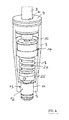
- the device 1 according to the invention for screwing components is designed as an electric Hubjetmotor comprising a linear motor 2 for the method of a shaft which simultaneously forms the output shaft 3 of the device 1, in its longitudinal axis and a torque motor 4 mounted on the linear motor 2 for rotating the shaft or output shaft 3 has about the longitudinal axis 5.
- an electric lifting motor is known from the prior art and is sold by the company NTE AG / LinMot (www.LinMot.com).
- the output shaft 3 can thus be moved back and forth in the direction of the longitudinal axis 5 in the direction of the double arrow 6 and driven in the opposite direction according to the double arrow 7 about the longitudinal axis 5.
- the device 1 further comprises a control device, not illustrated, for independently actuating the linear motor 2 and the rotary motor 4.
- a housing 9 of the rotary motor 4 is mounted in a stand 8, whereby the device 1 is mounted stationary in the stator 8, which is stationary.
- the housing 9 is firmly connected thereto. This is rotationally symmetrical with respect to the longitudinal axis 5 and thus firmly connected to the output shaft 3 both in the axial direction and in the direction of rotation.
- the housing 9 thus rotates at the same rotational speed as the output shaft 3.
- a further bore 11 is provided, in the region of a receptacle 12 is arranged for a screwing.
- This receptacle 12 is designed as a quick-change chuck for a screwdriver blade (as shown in particular the representation of Fig. 3 can be found).
- the outer diameter of a cylindrical portion 13 of the receptacle 12, wherein the portion 13 passes through the bore 11 is slightly smaller than the inner diameter of the housing 9 in the end portion which receives the receptacle 12, so that the receptacle 12 largely sealed passes through this region of the housing 9 ,
- a shut-off clutch 14 is arranged, which disengages upon reaching a certain torque, in particular a preset torque. This torque is for example 1 Nm.
- a first coupling part 15 of the shut-off clutch 14 is rotatably connected via a positive-locking element 16 with the output shaft 3 in the region of the lower, front-side end and there is a second coupling part 17 of the shut-off 14 rotatably connected to the receptacle 12.
- shut-off clutch 14 and all cooperating with these functional parts between the output shaft 3 and the receptacle 12 are disposed within the housing 9, which surrounds the rest, moreover, completely.
- the shut-off clutch 14 has a form-locking coupling, wherein the coupling part 17 is biased against the coupling part 15 under the action of a spring 18, which is designed as a helical compression spring.
- the coupling part 15 has two projections 19 directed towards the coupling part 17, wherein the respective projection 19 has a run-on slope 20 and a further slope 21.
- the two projections 19 are arranged diametrically, thus include a freewheeling angle of 180 °.
- the coupling part 17 has two projections 22. These are designed as balls.
- the two projections 22 and balls are also, relative to the longitudinal axis 5, arranged diametrically, thus also include a freewheeling angle of 180 °.
- a spring 18 which is designed as a helical compression spring.
- the coupling part 15 has two projections 19 directed towards the coupling part 17, wherein the respective projection 19 has a run-on slope 20 and a further slope 21.
- the two projections 19 are arranged diametrically, thus include
- the respective ball 22 is held in a receptacle 23 of a retaining ring 24 by the ball 22 protrudes into the associated receptacle 23.
- the spring 18 is effective between the retaining ring 24 and a arranged in the region of the receptacle 12 adjusting ring 25 for torque adjustment.
- This collar is in varying axial positions with respect to the receptacle 12 can be arranged and in a central telescopic shaft 26 which is rotatably connected to the coupling part 17, stored.
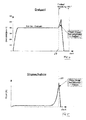
- the two coupling parts 15 and 17 are thus moved away from each other. Specifically, when screwing first the first coupling part 15 is in the region of the respective Projection, specifically the ramp 20 at the associated projection 22 and the associated ball of the coupling part 17 at. If a higher torque in the output shaft 3 is initiated, the ball 22 runs along the ramp 20, whereby the coupling member 17 is moved accordingly from the coupling member 15 away, to reach the vertex between the ramp 20 and the slope 21. This vertex represents the Shutdown 27 of the device is (see 4 and 5 ), with the aim to stop the rotation of the output shaft 3 immediately. After exceeding this vertex, the ball 22 is moved past the slope 21 of the projection 19 and the output shaft 3 is turned off before the ball 22 comes into the region of the next projection 19. Further, after crossing the vertex, the two coupling parts 15, 17 are moved toward each other again.
- the device 1 has an unillustrated electric speed controller which keeps a set speed of the output shaft 3 constant. This set speed, target / actual speed, for example, 400 / min.
- the rotary electric torque motor 4 which is coupled to a speed controller, thus keeps the set screwdriver speed (400 / min) constant.
- the set screwdriver speed 400 / min
- the engine speed increases jerkily, since the engine changes by the disengaging of load to idle. This short-term speed increase is used in the controller to stop the engine immediately.
- an increase of a set for the screwing constant speed of the output shaft when disengaging the shutdown clutch is thus determined or determined a drop in power consumption of the device when disengaging the shutdown.
- the stopping of the output shaft takes place immediately, in particular in front of a rotational position of the output shaft 3 in which a renewed automatic engagement of the shut-off takes place, therefore, before reaching the end of the freewheel.
Landscapes
- Engineering & Computer Science (AREA)
- Mechanical Engineering (AREA)
- Connection Of Motors, Electrical Generators, Mechanical Devices, And The Like (AREA)
Priority Applications (1)
| Application Number | Priority Date | Filing Date | Title |
|---|---|---|---|
| EP14165549.8A EP2937182A1 (fr) | 2014-04-23 | 2014-04-23 | Dispositif de vissage de composants |
Applications Claiming Priority (1)
| Application Number | Priority Date | Filing Date | Title |
|---|---|---|---|
| EP14165549.8A EP2937182A1 (fr) | 2014-04-23 | 2014-04-23 | Dispositif de vissage de composants |
Publications (1)
| Publication Number | Publication Date |
|---|---|
| EP2937182A1 true EP2937182A1 (fr) | 2015-10-28 |
Family
ID=50513135
Family Applications (1)
| Application Number | Title | Priority Date | Filing Date |
|---|---|---|---|
| EP14165549.8A Withdrawn EP2937182A1 (fr) | 2014-04-23 | 2014-04-23 | Dispositif de vissage de composants |
Country Status (1)
| Country | Link |
|---|---|
| EP (1) | EP2937182A1 (fr) |
Cited By (2)
| Publication number | Priority date | Publication date | Assignee | Title |
|---|---|---|---|---|
| CN112166010A (zh) * | 2018-05-18 | 2021-01-01 | 维拉工具有限责任公司 | 用于传递两个固定地设置的扭矩的旋拧工具 |
| SE548070C2 (en) * | 2025-04-30 | 2026-02-17 | Atlas Copco Ind Technique Ab | Pulse tool comprising a torque limiting clutch with an input and an output play |
Citations (5)
| Publication number | Priority date | Publication date | Assignee | Title |
|---|---|---|---|---|
| US5152046A (en) * | 1990-10-24 | 1992-10-06 | Sanyo Kiko Kabushiki Kaisha | Fastener tightening method |
| EP1579957A2 (fr) | 2004-03-23 | 2005-09-28 | Deprag Schulz Gmbh U. Co. | Tournevis à air comprimé |
| EP1623797A1 (fr) * | 2004-08-04 | 2006-02-08 | C. & E. Fein GmbH | Tournevis |
| DE202006003677U1 (de) | 2006-03-09 | 2007-07-19 | Deprag Schulz Gmbh U. Co | Kupplung und motorisch angetriebenes Drehwerkzeug |
| DE202008000753U1 (de) * | 2008-01-15 | 2008-03-20 | Hsieh, Chih-Ching | Die Konstruktion des Zahnformbauteils des Werkzeuges |
-
2014
- 2014-04-23 EP EP14165549.8A patent/EP2937182A1/fr not_active Withdrawn
Patent Citations (5)
| Publication number | Priority date | Publication date | Assignee | Title |
|---|---|---|---|---|
| US5152046A (en) * | 1990-10-24 | 1992-10-06 | Sanyo Kiko Kabushiki Kaisha | Fastener tightening method |
| EP1579957A2 (fr) | 2004-03-23 | 2005-09-28 | Deprag Schulz Gmbh U. Co. | Tournevis à air comprimé |
| EP1623797A1 (fr) * | 2004-08-04 | 2006-02-08 | C. & E. Fein GmbH | Tournevis |
| DE202006003677U1 (de) | 2006-03-09 | 2007-07-19 | Deprag Schulz Gmbh U. Co | Kupplung und motorisch angetriebenes Drehwerkzeug |
| DE202008000753U1 (de) * | 2008-01-15 | 2008-03-20 | Hsieh, Chih-Ching | Die Konstruktion des Zahnformbauteils des Werkzeuges |
Non-Patent Citations (1)
| Title |
|---|
| LANGE: "Industrielle Linearmotoren Für präzise und dynamische Positionieraufgaben Rein elektrisches Antriebssystem", 9 June 2013 (2013-06-09), XP055146148, Retrieved from the Internet <URL:http://www.linmot.com/fileadmin/doc/Overviews/Overview_Marketing_d_recent.pdf> [retrieved on 20141013] * |
Cited By (4)
| Publication number | Priority date | Publication date | Assignee | Title |
|---|---|---|---|---|
| CN112166010A (zh) * | 2018-05-18 | 2021-01-01 | 维拉工具有限责任公司 | 用于传递两个固定地设置的扭矩的旋拧工具 |
| CN112166010B (zh) * | 2018-05-18 | 2024-02-13 | 维拉工具有限责任公司 | 用于传递两个固定地设置的扭矩的旋拧工具 |
| SE548070C2 (en) * | 2025-04-30 | 2026-02-17 | Atlas Copco Ind Technique Ab | Pulse tool comprising a torque limiting clutch with an input and an output play |
| SE2530254A1 (en) * | 2025-04-30 | 2026-02-17 | Atlas Copco Ind Technique Ab | Pulse tool comprising a torque limiting clutch with an input and an output play |
Similar Documents
| Publication | Publication Date | Title |
|---|---|---|
| DE69718297T2 (de) | Angetriebener schraubenschlüssel mit drehmomentkupplung und einstellwerkzeug | |
| DE102008056438B4 (de) | Servomotor | |
| DE102010053226A1 (de) | Antriebseinrichtung | |
| DE102015205122B4 (de) | Schraubendreher | |
| EP3061549B1 (fr) | Barre de traction et/ou de compression | |
| DE102004038829A1 (de) | Schrauber | |
| DE102007035038A1 (de) | Automatische Drehmoment-Umschaltvorrichtung | |
| EP3733349A1 (fr) | Dispositif de serrage pour un raccordement à vis | |
| DE10103544A1 (de) | Schraubgerät | |
| EP1170093B1 (fr) | Outil de vissage | |
| EP2937183B1 (fr) | Procédé d'actionnement d'un dispositif de vissage de composants, et dispositif d'exécution du procédé | |
| DE3304195A1 (de) | Einrichtung zum eindrehen von schrauben | |
| EP0239670A2 (fr) | Machine motorisée avec réglage du couple, en particulier outillages électriques | |
| EP2937182A1 (fr) | Dispositif de vissage de composants | |
| EP3372343B1 (fr) | Dispositif comportant un bras de support déviant le moment de réaction et un tournevis | |
| WO2007101686A1 (fr) | Dispositif d'accouplement et outil rotatif motorisé | |
| EP1634352B1 (fr) | Pince a sertir | |
| EP0284755B1 (fr) | Dispositif de vissage | |
| EP3663046B1 (fr) | Dispositif tournevis ainsi que procédé de fonctionnement d'un dispositif tournevis | |
| EP1619414A2 (fr) | Actionneur | |
| DE20213740U1 (de) | Elektrohubzylinder | |
| DE19819251B4 (de) | Handnietgerät zum Setzen von Blindnietmuttern | |
| DE202006006273U1 (de) | Schraubgerät | |
| DE1938338C3 (de) | Vorrichtung zum maschinellen Ein- und Ausdrehen von Schienenbefestigungsschrauben | |
| EP1579939A1 (fr) | Outil |
Legal Events
| Date | Code | Title | Description |
|---|---|---|---|
| PUAI | Public reference made under article 153(3) epc to a published international application that has entered the european phase |
Free format text: ORIGINAL CODE: 0009012 |
|
| AK | Designated contracting states |
Kind code of ref document: A1 Designated state(s): AL AT BE BG CH CY CZ DE DK EE ES FI FR GB GR HR HU IE IS IT LI LT LU LV MC MK MT NL NO PL PT RO RS SE SI SK SM TR |
|
| AX | Request for extension of the european patent |
Extension state: BA ME |
|
| STAA | Information on the status of an ep patent application or granted ep patent |
Free format text: STATUS: THE APPLICATION IS DEEMED TO BE WITHDRAWN |
|
| 18D | Application deemed to be withdrawn |
Effective date: 20160429 |