EP2939901A1 - Système et procédé de commande de train - Google Patents
Système et procédé de commande de train Download PDFInfo
- Publication number
- EP2939901A1 EP2939901A1 EP13867115.1A EP13867115A EP2939901A1 EP 2939901 A1 EP2939901 A1 EP 2939901A1 EP 13867115 A EP13867115 A EP 13867115A EP 2939901 A1 EP2939901 A1 EP 2939901A1
- Authority
- EP
- European Patent Office
- Prior art keywords
- train
- radio communication
- ground
- route
- limit position
- Prior art date
- Legal status (The legal status is an assumption and is not a legal conclusion. Google has not performed a legal analysis and makes no representation as to the accuracy of the status listed.)
- Granted
Links
Images








Classifications
-
- B—PERFORMING OPERATIONS; TRANSPORTING
- B61—RAILWAYS
- B61L—GUIDING RAILWAY TRAFFIC; ENSURING THE SAFETY OF RAILWAY TRAFFIC
- B61L25/00—Recording or indicating positions or identities of vehicles or trains or setting of track apparatus
- B61L25/02—Indicating or recording positions or identities of vehicles or trains
- B61L25/025—Absolute localisation, e.g. providing geodetic coordinates
-
- B—PERFORMING OPERATIONS; TRANSPORTING
- B61—RAILWAYS
- B61L—GUIDING RAILWAY TRAFFIC; ENSURING THE SAFETY OF RAILWAY TRAFFIC
- B61L15/00—Indicators provided on the vehicle or train for signalling purposes
- B61L15/0018—Communication with or on the vehicle or train
- B61L15/0027—Radio-based, e.g. using GSM-R
-
- B—PERFORMING OPERATIONS; TRANSPORTING
- B61—RAILWAYS
- B61L—GUIDING RAILWAY TRAFFIC; ENSURING THE SAFETY OF RAILWAY TRAFFIC
- B61L23/00—Control, warning or like safety means along the route or between vehicles or trains
- B61L23/08—Control, warning or like safety means along the route or between vehicles or trains for controlling traffic in one direction only
- B61L23/14—Control, warning or like safety means along the route or between vehicles or trains for controlling traffic in one direction only automatically operated
-
- B—PERFORMING OPERATIONS; TRANSPORTING
- B61—RAILWAYS
- B61L—GUIDING RAILWAY TRAFFIC; ENSURING THE SAFETY OF RAILWAY TRAFFIC
- B61L23/00—Control, warning or like safety means along the route or between vehicles or trains
- B61L23/08—Control, warning or like safety means along the route or between vehicles or trains for controlling traffic in one direction only
- B61L23/14—Control, warning or like safety means along the route or between vehicles or trains for controlling traffic in one direction only automatically operated
- B61L23/18—Control, warning or like safety means along the route or between vehicles or trains for controlling traffic in one direction only automatically operated specially adapted for changing lengths of track sections in dependence upon speed and traffic density
-
- B—PERFORMING OPERATIONS; TRANSPORTING
- B61—RAILWAYS
- B61L—GUIDING RAILWAY TRAFFIC; ENSURING THE SAFETY OF RAILWAY TRAFFIC
- B61L27/00—Central railway traffic control systems; Trackside control; Communication systems specially adapted therefor
- B61L27/20—Trackside control of safe travel of vehicle or train, e.g. braking curve calculation
-
- B—PERFORMING OPERATIONS; TRANSPORTING
- B61—RAILWAYS
- B61L—GUIDING RAILWAY TRAFFIC; ENSURING THE SAFETY OF RAILWAY TRAFFIC
- B61L3/00—Devices along the route for controlling devices on the vehicle or train, e.g. to release brake or to operate a warning signal
- B61L3/02—Devices along the route for controlling devices on the vehicle or train, e.g. to release brake or to operate a warning signal at selected places along the route, e.g. intermittent control simultaneous mechanical and electrical control
Definitions
- the present embodiment relates to a train control system and a train control method.
- a train control system which notifies a train position detected by a train itself to a ground-side control device using wireless.
- it is possible to set a train stop limit position with a higher resolution than a security function using a track circuit of a current situation, and it is possible to reduce a train operation interval by the movement block.
- the track circuit needs a lot of complicated interconnections, less ground facilities are required and reduction in facility costs is also expected.
- Patent Document 1 Japanese Patent Publication No. 4301888
- a ground-side device cannot judge whether the train resides in front of a point, resides above the point, or has passed the point. Therefore, while the train resides in the radio communication disabled section, the point cannot be converted, and it is impossible to perform an operation such as overtaking by a high-class train.
- an interlocking control device also called an interlocking device
- the interlocking control device judges this situation as an "improper dropping", and might make all signal information stop indication, and thus, the train operation might be stopped.
- a problem to be solved by the present invention is to provide, in a train control system that notifies a train on-rail position from a train to a ground using wireless, a train control system and a train control method that enables the train to be operated, even when a radio communication disabled section occurs.
- a train control system of an embodiment is a train control system including ground radio communication means that transmits and receives information with on-board radio communication means of a train, ground communication means that is installed at a predetermined stop position at which the train stops, and transmits and receives information with the on-board communication means of the train, interlocking control means that performs a conversion of a point and a locking of a route, and ground control means that calculates a stop limit position to be given to each train, based on a train position and an opening state of a train route, and controls the interlocking control means so as to perform operation control of each train in a predetermined section, wherein the ground control means calculates a first stop limit position such that the train does not enter a calculated radio communication disruption section including all or part of a section in which the radio communication is disrupted between the ground radio communication means and the on-board radio communication means, calculates, with respect to a train that is made to travel through the calculated radio communication disruption section, a second stop limit position so that the train reaches up to
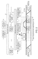
- Fig. 1 is a diagram that illustrates an entire configuration (outline) of a train control system described as an embodiment.
- an operation management device 1 a system management device 2, a ground control device 3, an interlocking control device 4, a ground radio communication device 5 and an antenna 6 thereof, an ATO (automatic train control) ground coil 7, a position correction ground coil 8, an inter-base network 9, and a wayside network 10 are installed on a ground side.
- ATO automatic train control
- the operation management device 1 performs a route setting request, or the like to the ground control device 3, based on a train operation diagram or an operation situation of a train 11.
- the system management device 2 performs operation situation monitoring, setting change, or the like of the entire system.
- the ground control device 3 receives train position information from each train 11 through the ground radio communication device 5 and the wayside network 10, grasps an on-rail situation of each train 11 from the received position information, transmits the information through the wayside network 10 to the operation management device 1 and the system management device 2, and further transmits the information to the interlocking control device 4.
- the interlocking control device 4 outputs a necessary command to a point device (point) 20, based on the information of the train on-rail situation from the ground control device 3 and the route setting request from the operation management device 1, performs a conversion or a lock of the point device 20, and transmits signal information (progress indication/stop indication) to the ground control device 3, based on a route opening situation.
- the ground control device 3 obtains an obstacle position (herein, an end position of the preceding train 11) as a leading end position of a progression-possible range of the (succeeding) train 11, from the signal information received from the interlocking control device 4 and the on-rail situation of the train 11, and sets a position upstream from that position by a security control margin distance, as a stop limit position, and transmits the information of the stop limit position to an on-board control device 12 through the ground radio communication device 5 and an on-board radio communication device 15.
- the information of the stop limit position like this is transmitted to the on-board control device 12 through an on-board coil 17 and the ATO ground coil 7.
- the ATO ground coil 7 performs communication with an ATO device 13 for the purpose of home door control or the like, and is necessarily installed at a stop position of the station. Since the train 11 stops above the ATO ground coil 7 or stops in the vicinity thereof, in the present embodiment, the ATO ground coil 7 is also used for communication between the ground control device 3 and the train 11 side.
- the position correction ground coil 8 is a ground coil that gives position information such that, using the given position information, a speed/position detection device 14 can correct the position information of its own train calculated by this device.
- the inter-base network 9 is a communication path that is established over an entire line section to be controlled by the corresponding train control system, communicably connects the operation management device 1 and the system management device 2, and a plurality of ground control devices 3, and also communicably connects the plurality of ground control devices 3 to one another.
- the wayside network 10 is a communication path that is established over a control range of the ground control device 3, communicably connects the ground control device 3 and a plurality of ground radio communication devices 5, and also communicably connects the plurality of ground radio communication devices 5 within the control range of the ground control device 3, to one another.
- the on-board control device 12, the ATO device (automatic train operation device) 13, the speed/position detection device 14, the on-board radio communication device 15 and an antenna 16 thereof, and the on-board coil 17 are installed on the train 11.
- the on-board control device 12 issues a brake command to a braking device (not illustrated) of the train 11, so that the train does not overrun the stop limit position received from the ground control device 3, and also the train speed does not exceed a speed limit.
- the ATO device 13 performs control, such as power running/braking of the train 11, on the vehicle.
- the train 11 travels on a rail 21, while wheels 19 are driven/braked by a driving/braking device (not illustrated), based on a power running/brake command of the ATO device 13, and stops above the ATO ground coil 7 installed at a predetermined stop position of the station with a predetermined accuracy.
- the speed/position detection device 14 counts the number of pulses of a TG (tachogenerator) 18, and detects a speed based on a wheel diameter and the number of teeth of the TG 18.
- the means that acquires the speed signal is not limited to the TG 18, and may use another means such as a pulse generator (PG).
- the speed/position detection device 14 calculates a moving distance by integrating the number of pulses of the TG 18 or the detected speed, and in addition, calculates the position of the own train, and further corrects the position information of the own train, based on the position information received from the position correction ground coil 8 through the on-board coil 17.
- the correction of the position information may be performed, such that the position information of the own train is corrected, based on ground coil installation position information read from a database (not illustrated), based on ground coil identification information received from the position correction ground coil 8 through the on-board coil 17.
- the position of the own train may be acquired using position information detected by the GPS device.
- the information acquired using the TG 18 or the GPS device may be mainly used as the position information of the own train, and the position information acquired from the other side may be used as auxiliary information for correction or the like.
- the speed/position detection device 14 transmits the position information of the own train which has been detected as described above, to the ground control device 3 through the on-board radio communication device 15 and the ground radio communication device 5. In addition, when the train 11 stops at a station, the speed/position detection device 14 also transmits the position information of the own train to the ground control device 3 through the on-board coil 17 and the ATO ground coil 7.
- the functions such as the information processing and the control in the operation management device 1, the system management device 2, the ground control device 3, the interlocking control device 4, and the on-board control device 12 can be realized using an information processing unit.
- the train control system of the present embodiment configured as described above has, as one feature, a point that the train control system not only performs the same radio communication as a conventional train control system that uses the radio communication by the ground radio communication device 5 and the on-board radio communication device 15, but also when the train 11 stops at the station, the train control system performs the communication between the ground control device 3 and the on-board control device 12 also through the on-board coil 17 and the ATO ground coil 7, transmits the information of the stop limit position from the ground side to the on-board control device 12, and transmits the position information of the train 11 from the on-board side to the ground control device 3.
- the train operation is interrupted on the both sides of the same section.
- a specific example of a case where the radio communication is disrupted will be described with reference to Fig. 3-1, Fig. 3-2 .
- the trains 11 will be described as a train A, a train B, ... , so as to distinguish the trains 11 from one another.
- the train B resides on the branch part, and in 302 in the same drawing, the train A having left the station stops in front of the branch part.
- the ground control device 3 cannot judge whether the train B having arrived at the station, or the train A having left the station stops in front of the branch part, or stops on the branch part, or is passing through the branch part. Therefore, it is impossible to convert the point device 20, until the radio communication is recovered, and it is confirmed that the train A or the train B is not on rail in the branch part.
- the interlocking control device 4 might detect "improper dropping", and the operation of each train 11 might be stopped.
- the trains A, B which have stuck in the radio communication disrupted section are guided and evacuated by the human system, and then, as indicated by 304 of Fig. 3-2 , when a train C is made to enter this section by a visual operation, the ground control device 3 cannot confirm that the train C is not on rail in the branch part, until the train C moves out of the section in which the radio communication is disrupted and the communication is recovered. Therefore, the point device 20 cannot be converted, and it is impossible to perform an operation to pass a train D through a main track, while the train C stops in a subsidiary main track.
- the interlocking control device 4 might detect "improper dropping", and the operation of each train 11 might be stopped.
- a plurality of routes are respectively defined in down and up directions in the interlocking control device 4.
- routes 0 to 3 are respectively defined for down and up directions.
- routes 0 to 5 are respectively defined for down and up directions.
- signal information of the virtual traffic signal is given from the interlocking control device 4 to the ground control device 3.
- the interlocking control device 4 in a case where the down train 11 intends to stop at the station through the route 0, when any route is unlocked, any virtual traffic signal is made to show stop indication.
- the interlocking control device 4 after confirming that the route 0 and the competing route 1 are unlocked and another train 11 is not present on the route 0, converts the point device 20 necessary for setting the route 0, sets the route 0, locks the route 0, and makes the virtual traffic signal of the entrance of the route 0 to show progress indication.
- the train 11 can enter the route 0 in which the progress indication is outputted.
- the interlocking control device 4 unlocks the route 0, because the train 11 has arrived at the last track circuit of the route. By this means, it becomes possible to set the route 1 for the next train 11.
- virtual traffic signals 33 illustrated in the drawing do not specifically exemplify the stop indication/progress indication, but are illustrated as symbols alone.
- the cases of the other routes illustrated in Fig. 4-1 and the routes illustrated in Fig. 4-2 to Fig. 4-4 are the same as the case of setting the route 0 illustrated in Fig. 4-1 as described above.
- the interlocking control device 4 After confirming that the route X and the competing route are unlocked, and another train 11 is not present on the route X, converts the point device 20 necessary for setting the route X, sets the route X, locks the route X, and makes the virtual traffic signal of the entrance of the route X show progress indication.
- the train 11 can enters the route X in which the progress indication is output, and when the train 11 arrives at the last track circuit of the route X, the interlocking control device 4 unlocks the route X. By this means, it becomes possible to set the route X and the competing route for the next train 11.
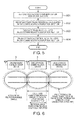
- Fig. 5 is a flow chart describing a basic processing of the train control system of the present embodiment
- Fig. 6 is a diagram describing a radio propagation range and a calculated radio communication disruption section in the present embodiment.
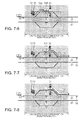
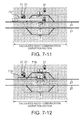
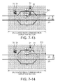
- Fig. 7-1 to Fig. 7-15 are diagrams describing specific operations of the train control system of the present embodiment.
- a situation is assumed that the train A having left the station from the subsidiary main track, the train B arriving at the station from the main track, and the train C subsequent to the train B are on rail.
- a stop limit position 30 immediately before each train 11 in the traveling direction indicates a stop limit position of each train 11.
- the virtual traffic signal 31 shows the stop indication and the virtual traffic signal 32 shows the progress indication.
- the basic processing of the train control system of the present embodiment (including the operation by the human system, such as the evacuation of the train 11) is shown in the flow chart shown in Fig. 5 . That is, to begin with, setting of the calculated radio communication disruption section is performed (A01), next, a processing of grasping whether the train 11 having stuck in the calculated radio communication disruption section is on the rail is performed (A02), next, evacuation of the train 11 having stuck in the calculated radio communication disruption section is performed (A03), and then, a train operation control is performed in the calculated radio communication disruption section (A04).
- setting of the calculated radio communication disruption section is performed (A01)
- A02 a processing of grasping whether the train 11 having stuck in the calculated radio communication disruption section is on the rail
- evacuation of the train 11 having stuck in the calculated radio communication disruption section is performed (A03)
- a train operation control is performed in the calculated radio communication disruption section (A04).
- the ground control device 3 sets the calculated radio communication disruption section, based on a radio propagation range (range in which a propagation strength above a certain level is ensured) of the ground radio communication device 5 from which abnormality has been detected, which is read from a database (not illustrated), based on identification information of the ground radio communication device 5 from which abnormality is detected.
- the radio propagation range of each ground radio communication device 5, which is present in the database is set as a minimum range of a changing radio propagation range that is covered by each ground radio communication device 5 (that is, a range in which a propagation strength above a certain level is ensured). Therefore, the calculated radio communication disruption section to be set in the above, is set wider than the range in which the radio communication has actually been disrupted, in consideration of uncertainty ( Fig. 6 : in the same drawing, the malfunction of the central ground radio communication device 5 is assumed). However, the calculated radio communication disruption section illustrated in Fig. 6 is an example, and can be set wider than the illustrated one.
- the method of detecting the malfunction of the radio communication device can use a method disclosed in, for example, Japanese Patent Application Publication No. 2007-124148 .
- the database can be configured by storing the identification information of the ground radio communication device 5 and the radio propagation range thereof in association with each other.
- the ground control device 3 regards a range from a lastly received train end position to a position of an upstream side (side into which the train 11 enters), out of the stop limit position of each of the trains A and B and the end position of the calculated radio communication disruption section (in the drawing, the right end position of the calculated radio communication disruption section), as an on-rail range of each of the trains A, B ( Fig. 7-2 : 702), and notifies the on-rail ranges to the interlocking control device 4.
- the ground control device 3 holds the lastly received train end positions, in order to determine the on-rail ranges of the trains A and B as described above.
- a stop limit position is given to the train C of the upstream side of the calculated radio communication disruption section, such that the train C does not enter the calculated radio communication disruption section.
- the stop limit position given to the train C will be retracted more in front (upstream side) than the stop limit position determined by the position of the preceding train 11 ( Fig. 7-2 : 703).
- the train C may not be able to stop before reaching a new stop limit position, depending on a distance to the start of the calculated radio communication disruption section (in the drawing, the left end of the calculated radio communication disruption section).
- the train A in which the route up to outside the calculated radio communication disruption section is ensured is advanced by visual operation guided by the human system ( Fig. 7-3 : 704).
- the communication with the ground control device 3 is recovered, and since the train A reports the position of the own train, the ground control device 3 can update the train position information, and the train A can be returned to the normal operation ( Fig. 7-4 : 705).
- the interlocking control device 4 is notified from the ground control device 3 that the train A has arrived at the end of the route, and unlocks the locked departure route ( Fig. 7-4 : 706).
- the on-rail information notified from the ground control device 3 since the on-rail range of the train A does not transit by skipping the middle of the route, the operation cannot be stopped by detecting abnormality (improper dropping) in the interlocking control device 4.
- the train B that is more upstream than the station stop position is guided by the human system and moved to the stop position by visual operation, because the route to the station stop position is taken ( Fig. 7-5 : 707). Since the train B stopped at a predetermined stop position reports the position of the own train to the ground control device 3 through the on-board coil 17 and the ATO ground coil 7, the ground control device 3 can update the train position information ( Fig. 7-6 : 708). After that, the interlocking control device 4 is notified from the ground control device 3 that the train B has arrived at the end of the route, and unlocks the locked route ( Fig. 7-6 : 709).
- both of the trains A, B which have stuck in the section at the time of occurrence of the calculated radio communication disruption section as described above are in a state that the trains A, B have advanced outside the calculated radio communication disruption section, or are in a state that the positions thereof can be grasped through the ATO ground coil 7, the trains are in a state in which the on-rail situation in the calculated radio communication disruption section can be grasped.
- the interlocking control device 4 sets the route ( Fig. 7-7 : 710) for the train B to depart from the station, based on the route setting request from the operation management device 1, locks the route, and makes the route signal information progress indication ( Fig. 7-7 : 32) .
- the ground control device 3 While the stop limit position of the train B calculated from the signal information from the interlocking control device 4 and the on-rail situation of each train 11 is more upstream than a position at which the end of the train can exit from the calculated radio communication disruption section, the ground control device 3 notifies the stop limit position in which a departure route entrance is made as an obstacle position, in place of the calculated stop limit position, to the on-board control device 12 of the train B, through the ATO ground coil 7 and the on-board coil 17. During this time, the train B remains stopped.
- the ground control device 3 transmits the stop limit position, the end position of the calculated radio communication disruption section, and an instruction to shift to a mode in which emergency stop is not performed even when the radio communication is disrupted (emergency brake is not applied), to the on-board control device 12 of the train B, through the ATO ground coil 7 and the on-board coil 17 ( Fig. 7-7 : 711). After that, the train B departs by an automatic operation.
- the train 11 emergently stops by applying the emergency brake, but, in the present embodiment, when the operation mode is shifted to the "mode in which emergency stop is not performed even when the radio communication is disrupted", the automatic operation is possible because the train 11 continuously operates without stop even when the radio communication is disrupted.
- the ground control device 3 regards a range from a lastly received train end position (end position when the train stops at the station) to a position of the upstream side, out of the stop limit position of the train B and the end position of the calculated radio communication disruption section, as the on-rail range of the train B ( Fig. 7-8 : 712).
- the ground control device 3 can update the train position information, and the train B can release the mode in which emergency stop is not performed even when the radio communication is disrupted, and can return to the normal operation ( Fig. 7-9 : 713).
- the interlocking control device 4 is notified from the ground control device 3 that the train B has arrived at the end of the route, and unlocks the locked departure route ( Fig. 7-9 : 714). Regarding the on-rail information notified from the ground control device 3, since the on-rail range of the train B does not transit by skipping the middle of the route, the operation cannot be stopped by detecting abnormality (improper dropping) in the interlocking control device 4.
- the interlocking control device 4 issues a conversion command of the point device 20, based on the route setting request from the operation management device 1, sets the route ( Fig. 7-10 : 715) for the train C to arrive at the station, locks the route, and makes the route signal information progress indication ( Fig. 7-10 : 32).
- the ground control device 3 While the stop limit position of the train C calculated from the signal information from the interlocking control device 4 and the on-rail situation of the train B is more upstream than a position that can reach up to a predetermined station stop position (ATO ground coil 7), the ground control device 3 notifies the stop limit position in which the start of the calculated radio communication disruption section is made as an obstacle position, in place of the calculated stop limit position, to the train C by radio communication. By this means, the train C does not enter the calculated radio communication disruption section.
- the ground control device 3 transmits the stop limit position that is the position at which the communication can be performed with the ground coil 7 when the train is stopped, the end position of the calculated radio communication disruption section, and an instruction to shift to the mode in which the emergency stop is not performed even when the radio communication is disrupted, to the train C by radio communication.
- the ground control device 3 transmits the stop limit position, the end position of the calculated radio communication disruption section, and an instruction to shift to the mode in which the emergency stop is not performed even when the radio communication is disrupted, to the train C by radio communication ( Fig. 7-10 : 716).
- the train C enters the calculated radio communication disruption section by automatic operation, and travels the set route ( Fig. 7-10 : 715).
- the ground control device 3 regards a range from a lastly received train end position to the position of the more upstream side, out of the stop limit position of the train C and the end position of the calculated radio communication disruption section, as the on-rail range of the train C ( Fig. 7-11 : 717).
- the ground control device 3 can update the train position information ( Fig. 7-12 : 718).
- the interlocking control device 4 is notified from the ground control device 3 that the train C has arrived at the end of the route, and unlocks the locked route ( Fig. 7-12 : 719).
- an operation that enables the train C to overtake the train B can be performed, by setting and locking the route passing through the station, and by giving the stop limit position so that the train can advance the calculated radio communication disruption section in 716 of Fig. 7-10 .
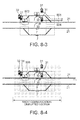
- Fig. 8-1 to Fig. 8-6 are diagrams describing the operation of the case where the calculated radio communication disruption section occurs in the middle of the route setting change in the train control system of the embodiment.
- the manner of description in Fig. 8-1 to Fig. 8-6 conforms to that is Fig. 7-1 to Fig. 7-15 described above.
- the operation management device 1 requests the interlocking control device 4 to unlock the main track departure route, and to lock the subsidiary track departure route.
- the interlocking control device 4 makes the signal information with respect to the main track departure route stop indication ( Fig. 8-2 : 801), and based on this, the ground control device 3 calculates the stop limit position in which the main track departure route entrance is made the obstacle position. At this time, the stop limit position of the train E is retracted ( Fig. 8-2 : 802).
- the ground control device 3 notifies the calculated stop limit position to the on-board control device 12 of the train E.
- the on-board control device 12 of the train E responds to the ground control device 3 that the train E can stop before reaching the new stop limit position ( Fig. 8-3 : 803). And having received the response, the ground control device 3 notifies that the route of the stop indication can be unlocked, to the interlocking control device 4.
- the interlocking control device 4 waits for the time necessary for the train E to stop, unlocks the main track departure route ( Fig. 8-3 : 804), sets the subsidiary main track departure route ( Fig. 8-3 : 805) for the train D, and locks the route.
- the ground control device 3 notifies to the interlocking control device 4 such that: (1) “unlocking impossible” with respect to the route of the progress indication, (2) “unlocking possible” with respect to the route of the stop indication, in a case where the notification that the train can stop up to the route entrance is obtained from the on-board control device 12, and (3) “unlocking impossible” in the other cases.
- the ground control device 3 Having not obtained the information indicating "the train can stop up to the main track departure route entrance" from the on-board control device 12 of the train E, the ground control device 3 notifies the interlocking control device 4 of "unlocking impossible” with respect to the main track departure route ( Fig. 8-5 : 807).
- the ground control device 3 sets the calculated radio communication disruption section, as described above, and performs control while regarding the range illustrated in Fig. 8-5 : 808, as the on-rail range of the train E.
- the interlocking control device 4 can unlock the set route before the train enters the set route, only when the information of "unlocking possible” is obtained.
- the information of "unlocking impossible” is notified from the ground control device 3, since the main track departure route remains locked, the safety is ensured.
- the on-board control device 12 can receive a new stop limit position from the ground control device 3 through the ATO ground coil 7, and can return the information indicating that the train can stop before reaching the stop limit position", and thereby the ground control device 3 notifies "unlocking possible" to the interlocking control device 4. Having received this notification, the interlocking control device 4 can safely unlock the main track departure route ( Fig. 8-6 : 810).
- the train control system of the above-described embodiments in the train control system which notifies the train on-rail position from the train to the ground side control device using wireless, even when the radio communication disabled section occurs in all or part of the interlocking control section, the operations such as overtaking and waiting in this section can be realized at low costs, while safety is ensured.
Landscapes
- Engineering & Computer Science (AREA)
- Mechanical Engineering (AREA)
- Train Traffic Observation, Control, And Security (AREA)
- Electric Propulsion And Braking For Vehicles (AREA)
Applications Claiming Priority (2)
| Application Number | Priority Date | Filing Date | Title |
|---|---|---|---|
| JP2012287515A JP5885654B2 (ja) | 2012-12-28 | 2012-12-28 | 列車制御システム |
| PCT/JP2013/005317 WO2014103102A1 (fr) | 2012-12-28 | 2013-09-09 | Système et procédé de commande de train |
Publications (3)
| Publication Number | Publication Date |
|---|---|
| EP2939901A1 true EP2939901A1 (fr) | 2015-11-04 |
| EP2939901A4 EP2939901A4 (fr) | 2016-09-21 |
| EP2939901B1 EP2939901B1 (fr) | 2018-03-21 |
Family
ID=51020245
Family Applications (1)
| Application Number | Title | Priority Date | Filing Date |
|---|---|---|---|
| EP13867115.1A Not-in-force EP2939901B1 (fr) | 2012-12-28 | 2013-09-09 | Système et procédé de commande de train |
Country Status (5)
| Country | Link |
|---|---|
| EP (1) | EP2939901B1 (fr) |
| JP (1) | JP5885654B2 (fr) |
| CN (1) | CN104583052B (fr) |
| IN (1) | IN2015DN01601A (fr) |
| WO (1) | WO2014103102A1 (fr) |
Cited By (4)
| Publication number | Priority date | Publication date | Assignee | Title |
|---|---|---|---|---|
| CN107128336A (zh) * | 2017-04-25 | 2017-09-05 | 王昌兴 | 有轨机车组抛停加挂系统及方法 |
| WO2018021606A1 (fr) * | 2016-07-28 | 2018-02-01 | 한국철도기술연구원 | Système de verrouillage électronique embarqué et procédé associé destinés à un système de commande de train autonome basé sur une connexion entre trains |
| EP3495233A4 (fr) * | 2016-08-04 | 2019-11-06 | Mitsubishi Electric Corporation | Système de commande de train sans fil et procédé de commande de train sans fil |
| US10513278B2 (en) | 2016-05-12 | 2019-12-24 | Kyosan Electric Mfg. Co., Ltd. | Ground apparatus |
Families Citing this family (17)
| Publication number | Priority date | Publication date | Assignee | Title |
|---|---|---|---|---|
| JP6310868B2 (ja) * | 2015-02-12 | 2018-04-11 | 株式会社日立製作所 | 進路制御システム、進路制御方法、及び地上装置 |
| JP6541563B2 (ja) * | 2015-12-10 | 2019-07-10 | 株式会社日立製作所 | 鉄道保安システム及び連動装置 |
| CN109070903B (zh) * | 2016-05-12 | 2020-02-14 | 株式会社京三制作所 | 地面装置 |
| WO2017195313A1 (fr) * | 2016-05-12 | 2017-11-16 | 株式会社京三製作所 | Système de commande de train |
| JP6799432B2 (ja) * | 2016-10-13 | 2020-12-16 | 東日本旅客鉄道株式会社 | 鉄道車両の走行距離実績把握システム |
| JP6925144B2 (ja) * | 2017-03-22 | 2021-08-25 | 株式会社日立製作所 | 無線列車制御システム及びその地上側制御装置 |
| CN109285345A (zh) * | 2018-09-06 | 2019-01-29 | 杭州飞遁科技有限公司 | 一种交通运行网络故障调配处理方法 |
| JP7349384B2 (ja) * | 2020-02-13 | 2023-09-22 | 東日本旅客鉄道株式会社 | 中央装置 |
| CN111746597A (zh) * | 2020-06-11 | 2020-10-09 | 中铁第四勘察设计院集团有限公司 | 一种列车停车控制系统及方法 |
| CN111746596A (zh) * | 2020-06-11 | 2020-10-09 | 中铁第四勘察设计院集团有限公司 | 一种列车停车控制方法和装置 |
| CN112061180B (zh) * | 2020-08-28 | 2022-07-19 | 交控科技股份有限公司 | 一种道岔侧冲防护方法及系统 |
| US11722210B2 (en) * | 2021-01-12 | 2023-08-08 | Tencent America LLC | Unmanned aerial system communication |
| CN114228788B (zh) * | 2021-12-13 | 2023-09-08 | 卡斯柯信号有限公司 | 一种失位列车的轨旁辅助定位方法、装置、设备及介质 |
| CN115140125B (zh) * | 2022-08-19 | 2023-08-18 | 中国人民解放军国防科技大学 | 基于ldv、uwb、mems组合的列车定位方法 |
| WO2024048075A1 (fr) * | 2022-08-31 | 2024-03-07 | 株式会社日立製作所 | Système de commande de train |
| CN115923887B (zh) * | 2023-03-10 | 2023-05-05 | 北京全路通信信号研究设计院集团有限公司 | 一种列车进路办理方法、装置、电子设备及存储介质 |
| CN116395004B (zh) * | 2023-06-08 | 2023-08-15 | 北京全路通信信号研究设计院集团有限公司 | 一种列车运行控制方法及系统 |
Family Cites Families (9)
| Publication number | Priority date | Publication date | Assignee | Title |
|---|---|---|---|---|
| JPH11245818A (ja) * | 1998-03-06 | 1999-09-14 | Toshiba Corp | 列車通信装置および方法 |
| JP4070490B2 (ja) * | 2002-03-27 | 2008-04-02 | 株式会社京三製作所 | 列車制御システム、及び列車制御方法 |
| JP4301888B2 (ja) * | 2003-08-27 | 2009-07-22 | 日本信号株式会社 | 列車制御装置 |
| JP4714490B2 (ja) * | 2005-03-18 | 2011-06-29 | 北海道旅客鉄道株式会社 | 車載装置及び運行管理装置 |
| JP2006298069A (ja) * | 2005-04-18 | 2006-11-02 | Toshiba Corp | 無線列車制御システム |
| JP4641245B2 (ja) | 2005-10-26 | 2011-03-02 | 三菱電機株式会社 | アドホック・ネットワーク・システム、無線アドホック端末およびその故障検出方法 |
| JP4471996B2 (ja) * | 2007-09-18 | 2010-06-02 | 株式会社日立製作所 | 列車制御システム |
| JP5268737B2 (ja) * | 2009-03-27 | 2013-08-21 | 株式会社日立製作所 | 無線列車制御システム,無線列車制御車上システムおよび無線列車制御地上システム |
| JP5355495B2 (ja) * | 2010-01-13 | 2013-11-27 | 株式会社日立製作所 | 信号保安システム |
-
2012
- 2012-12-28 JP JP2012287515A patent/JP5885654B2/ja not_active Expired - Fee Related
-
2013
- 2013-09-09 CN CN201380045098.6A patent/CN104583052B/zh not_active Expired - Fee Related
- 2013-09-09 IN IN1601DEN2015 patent/IN2015DN01601A/en unknown
- 2013-09-09 EP EP13867115.1A patent/EP2939901B1/fr not_active Not-in-force
- 2013-09-09 WO PCT/JP2013/005317 patent/WO2014103102A1/fr not_active Ceased
Cited By (4)
| Publication number | Priority date | Publication date | Assignee | Title |
|---|---|---|---|---|
| US10513278B2 (en) | 2016-05-12 | 2019-12-24 | Kyosan Electric Mfg. Co., Ltd. | Ground apparatus |
| WO2018021606A1 (fr) * | 2016-07-28 | 2018-02-01 | 한국철도기술연구원 | Système de verrouillage électronique embarqué et procédé associé destinés à un système de commande de train autonome basé sur une connexion entre trains |
| EP3495233A4 (fr) * | 2016-08-04 | 2019-11-06 | Mitsubishi Electric Corporation | Système de commande de train sans fil et procédé de commande de train sans fil |
| CN107128336A (zh) * | 2017-04-25 | 2017-09-05 | 王昌兴 | 有轨机车组抛停加挂系统及方法 |
Also Published As
| Publication number | Publication date |
|---|---|
| JP5885654B2 (ja) | 2016-03-15 |
| EP2939901A4 (fr) | 2016-09-21 |
| IN2015DN01601A (fr) | 2015-07-03 |
| CN104583052B (zh) | 2016-11-09 |
| WO2014103102A1 (fr) | 2014-07-03 |
| JP2014129029A (ja) | 2014-07-10 |
| CN104583052A (zh) | 2015-04-29 |
| EP2939901B1 (fr) | 2018-03-21 |
Similar Documents
| Publication | Publication Date | Title |
|---|---|---|
| EP2939901B1 (fr) | Système et procédé de commande de train | |
| US9884635B2 (en) | Signaling system and door control method | |
| US10293842B2 (en) | On-board device, signaling system, and control method of moving vehicle | |
| US9669853B2 (en) | Train control system | |
| US20160046306A1 (en) | On-board device, signaling system and control method of moving vehicle | |
| US9522688B2 (en) | On-board device, signaling system, and control method of moving vehicle | |
| US9849897B2 (en) | Signaling system and control method of moving vehicle | |
| EP2937259B1 (fr) | Dispositif de commande de train, et procédé de commande de train | |
| CN107709136B (zh) | 用于为轨道车辆确定行驶授权的方法和装置 | |
| JP7535970B2 (ja) | 自動列車運転システムの車上装置 | |
| US20140214247A1 (en) | Train control system | |
| WO2014064826A1 (fr) | Dispositif et procédé de détection de présence sur voie ferrée | |
| WO2014064825A1 (fr) | Dispositif permettant d'établir une estimation de la plage occupée par un train, dispositif embarqué, et procédé permettant d'établir une estimation de la plage occupée par un train | |
| TW201410525A (zh) | 車上裝置、地上裝置及門控制方法 | |
| JP5300366B2 (ja) | 自動列車制御装置 | |
| JP2013023037A (ja) | 列車制御装置 | |
| JP2010259167A (ja) | 車両 | |
| JP5470315B2 (ja) | 信号制御システム | |
| JP2010136561A (ja) | 列車運転制御方法及び列車運転制御装置 | |
| JPWO2018207480A1 (ja) | 自動列車保安装置及び車上装置 | |
| JP2015139297A (ja) | 列車制御システム | |
| JP2015033177A (ja) | 鉄道車両および鉄道車両制御システム | |
| JP5452544B2 (ja) | 信号制御システム | |
| JP5334786B2 (ja) | 列車保安制御システム | |
| JP5596621B2 (ja) | 列車制御方法及び列車制御システム |
Legal Events
| Date | Code | Title | Description |
|---|---|---|---|
| PUAI | Public reference made under article 153(3) epc to a published international application that has entered the european phase |
Free format text: ORIGINAL CODE: 0009012 |
|
| 17P | Request for examination filed |
Effective date: 20150319 |
|
| AK | Designated contracting states |
Kind code of ref document: A1 Designated state(s): AL AT BE BG CH CY CZ DE DK EE ES FI FR GB GR HR HU IE IS IT LI LT LU LV MC MK MT NL NO PL PT RO RS SE SI SK SM TR |
|
| AX | Request for extension of the european patent |
Extension state: BA ME |
|
| DAX | Request for extension of the european patent (deleted) | ||
| A4 | Supplementary search report drawn up and despatched |
Effective date: 20160823 |
|
| RIC1 | Information provided on ipc code assigned before grant |
Ipc: B61L 27/00 20060101ALI20160817BHEP Ipc: B61L 3/12 20060101ALI20160817BHEP Ipc: B61L 25/02 20060101ALI20160817BHEP Ipc: B61L 15/00 20060101ALI20160817BHEP Ipc: B61L 3/02 20060101ALI20160817BHEP Ipc: B61L 23/14 20060101AFI20160817BHEP Ipc: B61L 23/18 20060101ALI20160817BHEP |
|
| GRAP | Despatch of communication of intention to grant a patent |
Free format text: ORIGINAL CODE: EPIDOSNIGR1 |
|
| STAA | Information on the status of an ep patent application or granted ep patent |
Free format text: STATUS: GRANT OF PATENT IS INTENDED |
|
| RIC1 | Information provided on ipc code assigned before grant |
Ipc: B61L 15/00 20060101ALI20170427BHEP Ipc: B61L 23/18 20060101ALI20170427BHEP Ipc: B61L 3/12 20060101ALI20170427BHEP Ipc: B61L 25/02 20060101ALI20170427BHEP Ipc: B61L 3/02 20060101ALI20170427BHEP Ipc: B61L 23/14 20060101AFI20170427BHEP Ipc: B61L 27/00 20060101ALI20170427BHEP |
|
| INTG | Intention to grant announced |
Effective date: 20170522 |
|
| GRAJ | Information related to disapproval of communication of intention to grant by the applicant or resumption of examination proceedings by the epo deleted |
Free format text: ORIGINAL CODE: EPIDOSDIGR1 |
|
| STAA | Information on the status of an ep patent application or granted ep patent |
Free format text: STATUS: REQUEST FOR EXAMINATION WAS MADE |
|
| GRAP | Despatch of communication of intention to grant a patent |
Free format text: ORIGINAL CODE: EPIDOSNIGR1 |
|
| STAA | Information on the status of an ep patent application or granted ep patent |
Free format text: STATUS: GRANT OF PATENT IS INTENDED |
|
| INTC | Intention to grant announced (deleted) | ||
| INTG | Intention to grant announced |
Effective date: 20171030 |
|
| GRAS | Grant fee paid |
Free format text: ORIGINAL CODE: EPIDOSNIGR3 |
|
| GRAA | (expected) grant |
Free format text: ORIGINAL CODE: 0009210 |
|
| STAA | Information on the status of an ep patent application or granted ep patent |
Free format text: STATUS: THE PATENT HAS BEEN GRANTED |
|
| AK | Designated contracting states |
Kind code of ref document: B1 Designated state(s): AL AT BE BG CH CY CZ DE DK EE ES FI FR GB GR HR HU IE IS IT LI LT LU LV MC MK MT NL NO PL PT RO RS SE SI SK SM TR |
|
| REG | Reference to a national code |
Ref country code: GB Ref legal event code: FG4D |
|
| REG | Reference to a national code |
Ref country code: CH Ref legal event code: EP |
|
| REG | Reference to a national code |
Ref country code: AT Ref legal event code: REF Ref document number: 980761 Country of ref document: AT Kind code of ref document: T Effective date: 20180415 |
|
| REG | Reference to a national code |
Ref country code: IE Ref legal event code: FG4D |
|
| REG | Reference to a national code |
Ref country code: DE Ref legal event code: R096 Ref document number: 602013034896 Country of ref document: DE |
|
| REG | Reference to a national code |
Ref country code: NL Ref legal event code: MP Effective date: 20180321 |
|
| PG25 | Lapsed in a contracting state [announced via postgrant information from national office to epo] |
Ref country code: CY Free format text: LAPSE BECAUSE OF FAILURE TO SUBMIT A TRANSLATION OF THE DESCRIPTION OR TO PAY THE FEE WITHIN THE PRESCRIBED TIME-LIMIT Effective date: 20180321 Ref country code: HR Free format text: LAPSE BECAUSE OF FAILURE TO SUBMIT A TRANSLATION OF THE DESCRIPTION OR TO PAY THE FEE WITHIN THE PRESCRIBED TIME-LIMIT Effective date: 20180321 Ref country code: NO Free format text: LAPSE BECAUSE OF FAILURE TO SUBMIT A TRANSLATION OF THE DESCRIPTION OR TO PAY THE FEE WITHIN THE PRESCRIBED TIME-LIMIT Effective date: 20180621 Ref country code: FI Free format text: LAPSE BECAUSE OF FAILURE TO SUBMIT A TRANSLATION OF THE DESCRIPTION OR TO PAY THE FEE WITHIN THE PRESCRIBED TIME-LIMIT Effective date: 20180321 Ref country code: LT Free format text: LAPSE BECAUSE OF FAILURE TO SUBMIT A TRANSLATION OF THE DESCRIPTION OR TO PAY THE FEE WITHIN THE PRESCRIBED TIME-LIMIT Effective date: 20180321 |
|
| REG | Reference to a national code |
Ref country code: LT Ref legal event code: MG4D |
|
| REG | Reference to a national code |
Ref country code: FR Ref legal event code: PLFP Year of fee payment: 6 |
|
| REG | Reference to a national code |
Ref country code: AT Ref legal event code: MK05 Ref document number: 980761 Country of ref document: AT Kind code of ref document: T Effective date: 20180321 |
|
| PG25 | Lapsed in a contracting state [announced via postgrant information from national office to epo] |
Ref country code: LV Free format text: LAPSE BECAUSE OF FAILURE TO SUBMIT A TRANSLATION OF THE DESCRIPTION OR TO PAY THE FEE WITHIN THE PRESCRIBED TIME-LIMIT Effective date: 20180321 Ref country code: SE Free format text: LAPSE BECAUSE OF FAILURE TO SUBMIT A TRANSLATION OF THE DESCRIPTION OR TO PAY THE FEE WITHIN THE PRESCRIBED TIME-LIMIT Effective date: 20180321 Ref country code: RS Free format text: LAPSE BECAUSE OF FAILURE TO SUBMIT A TRANSLATION OF THE DESCRIPTION OR TO PAY THE FEE WITHIN THE PRESCRIBED TIME-LIMIT Effective date: 20180321 Ref country code: BG Free format text: LAPSE BECAUSE OF FAILURE TO SUBMIT A TRANSLATION OF THE DESCRIPTION OR TO PAY THE FEE WITHIN THE PRESCRIBED TIME-LIMIT Effective date: 20180621 Ref country code: GR Free format text: LAPSE BECAUSE OF FAILURE TO SUBMIT A TRANSLATION OF THE DESCRIPTION OR TO PAY THE FEE WITHIN THE PRESCRIBED TIME-LIMIT Effective date: 20180622 |
|
| PG25 | Lapsed in a contracting state [announced via postgrant information from national office to epo] |
Ref country code: ES Free format text: LAPSE BECAUSE OF FAILURE TO SUBMIT A TRANSLATION OF THE DESCRIPTION OR TO PAY THE FEE WITHIN THE PRESCRIBED TIME-LIMIT Effective date: 20180321 Ref country code: AL Free format text: LAPSE BECAUSE OF FAILURE TO SUBMIT A TRANSLATION OF THE DESCRIPTION OR TO PAY THE FEE WITHIN THE PRESCRIBED TIME-LIMIT Effective date: 20180321 Ref country code: RO Free format text: LAPSE BECAUSE OF FAILURE TO SUBMIT A TRANSLATION OF THE DESCRIPTION OR TO PAY THE FEE WITHIN THE PRESCRIBED TIME-LIMIT Effective date: 20180321 Ref country code: EE Free format text: LAPSE BECAUSE OF FAILURE TO SUBMIT A TRANSLATION OF THE DESCRIPTION OR TO PAY THE FEE WITHIN THE PRESCRIBED TIME-LIMIT Effective date: 20180321 Ref country code: NL Free format text: LAPSE BECAUSE OF FAILURE TO SUBMIT A TRANSLATION OF THE DESCRIPTION OR TO PAY THE FEE WITHIN THE PRESCRIBED TIME-LIMIT Effective date: 20180321 Ref country code: PL Free format text: LAPSE BECAUSE OF FAILURE TO SUBMIT A TRANSLATION OF THE DESCRIPTION OR TO PAY THE FEE WITHIN THE PRESCRIBED TIME-LIMIT Effective date: 20180321 |
|
| PGFP | Annual fee paid to national office [announced via postgrant information from national office to epo] |
Ref country code: DE Payment date: 20180828 Year of fee payment: 6 Ref country code: IT Payment date: 20180919 Year of fee payment: 6 Ref country code: FR Payment date: 20180813 Year of fee payment: 6 |
|
| PG25 | Lapsed in a contracting state [announced via postgrant information from national office to epo] |
Ref country code: SK Free format text: LAPSE BECAUSE OF FAILURE TO SUBMIT A TRANSLATION OF THE DESCRIPTION OR TO PAY THE FEE WITHIN THE PRESCRIBED TIME-LIMIT Effective date: 20180321 Ref country code: AT Free format text: LAPSE BECAUSE OF FAILURE TO SUBMIT A TRANSLATION OF THE DESCRIPTION OR TO PAY THE FEE WITHIN THE PRESCRIBED TIME-LIMIT Effective date: 20180321 Ref country code: CZ Free format text: LAPSE BECAUSE OF FAILURE TO SUBMIT A TRANSLATION OF THE DESCRIPTION OR TO PAY THE FEE WITHIN THE PRESCRIBED TIME-LIMIT Effective date: 20180321 Ref country code: SM Free format text: LAPSE BECAUSE OF FAILURE TO SUBMIT A TRANSLATION OF THE DESCRIPTION OR TO PAY THE FEE WITHIN THE PRESCRIBED TIME-LIMIT Effective date: 20180321 |
|
| PG25 | Lapsed in a contracting state [announced via postgrant information from national office to epo] |
Ref country code: PT Free format text: LAPSE BECAUSE OF FAILURE TO SUBMIT A TRANSLATION OF THE DESCRIPTION OR TO PAY THE FEE WITHIN THE PRESCRIBED TIME-LIMIT Effective date: 20180723 |
|
| REG | Reference to a national code |
Ref country code: DE Ref legal event code: R097 Ref document number: 602013034896 Country of ref document: DE |
|
| PLBE | No opposition filed within time limit |
Free format text: ORIGINAL CODE: 0009261 |
|
| STAA | Information on the status of an ep patent application or granted ep patent |
Free format text: STATUS: NO OPPOSITION FILED WITHIN TIME LIMIT |
|
| PG25 | Lapsed in a contracting state [announced via postgrant information from national office to epo] |
Ref country code: DK Free format text: LAPSE BECAUSE OF FAILURE TO SUBMIT A TRANSLATION OF THE DESCRIPTION OR TO PAY THE FEE WITHIN THE PRESCRIBED TIME-LIMIT Effective date: 20180321 |
|
| 26N | No opposition filed |
Effective date: 20190102 |
|
| PG25 | Lapsed in a contracting state [announced via postgrant information from national office to epo] |
Ref country code: MC Free format text: LAPSE BECAUSE OF FAILURE TO SUBMIT A TRANSLATION OF THE DESCRIPTION OR TO PAY THE FEE WITHIN THE PRESCRIBED TIME-LIMIT Effective date: 20180321 |
|
| REG | Reference to a national code |
Ref country code: CH Ref legal event code: PL |
|
| GBPC | Gb: european patent ceased through non-payment of renewal fee |
Effective date: 20180909 |
|
| PG25 | Lapsed in a contracting state [announced via postgrant information from national office to epo] |
Ref country code: SI Free format text: LAPSE BECAUSE OF FAILURE TO SUBMIT A TRANSLATION OF THE DESCRIPTION OR TO PAY THE FEE WITHIN THE PRESCRIBED TIME-LIMIT Effective date: 20180321 |
|
| REG | Reference to a national code |
Ref country code: BE Ref legal event code: MM Effective date: 20180930 |
|
| REG | Reference to a national code |
Ref country code: IE Ref legal event code: MM4A |
|
| PG25 | Lapsed in a contracting state [announced via postgrant information from national office to epo] |
Ref country code: LU Free format text: LAPSE BECAUSE OF NON-PAYMENT OF DUE FEES Effective date: 20180909 |
|
| PG25 | Lapsed in a contracting state [announced via postgrant information from national office to epo] |
Ref country code: IE Free format text: LAPSE BECAUSE OF NON-PAYMENT OF DUE FEES Effective date: 20180909 |
|
| PG25 | Lapsed in a contracting state [announced via postgrant information from national office to epo] |
Ref country code: CH Free format text: LAPSE BECAUSE OF NON-PAYMENT OF DUE FEES Effective date: 20180930 Ref country code: LI Free format text: LAPSE BECAUSE OF NON-PAYMENT OF DUE FEES Effective date: 20180930 Ref country code: BE Free format text: LAPSE BECAUSE OF NON-PAYMENT OF DUE FEES Effective date: 20180930 |
|
| PG25 | Lapsed in a contracting state [announced via postgrant information from national office to epo] |
Ref country code: GB Free format text: LAPSE BECAUSE OF NON-PAYMENT OF DUE FEES Effective date: 20180909 |
|
| PG25 | Lapsed in a contracting state [announced via postgrant information from national office to epo] |
Ref country code: MT Free format text: LAPSE BECAUSE OF NON-PAYMENT OF DUE FEES Effective date: 20180909 |
|
| PG25 | Lapsed in a contracting state [announced via postgrant information from national office to epo] |
Ref country code: TR Free format text: LAPSE BECAUSE OF FAILURE TO SUBMIT A TRANSLATION OF THE DESCRIPTION OR TO PAY THE FEE WITHIN THE PRESCRIBED TIME-LIMIT Effective date: 20180321 |
|
| REG | Reference to a national code |
Ref country code: DE Ref legal event code: R119 Ref document number: 602013034896 Country of ref document: DE |
|
| PG25 | Lapsed in a contracting state [announced via postgrant information from national office to epo] |
Ref country code: HU Free format text: LAPSE BECAUSE OF FAILURE TO SUBMIT A TRANSLATION OF THE DESCRIPTION OR TO PAY THE FEE WITHIN THE PRESCRIBED TIME-LIMIT; INVALID AB INITIO Effective date: 20130909 Ref country code: MK Free format text: LAPSE BECAUSE OF NON-PAYMENT OF DUE FEES Effective date: 20180321 |
|
| PG25 | Lapsed in a contracting state [announced via postgrant information from national office to epo] |
Ref country code: DE Free format text: LAPSE BECAUSE OF NON-PAYMENT OF DUE FEES Effective date: 20200401 Ref country code: IS Free format text: LAPSE BECAUSE OF FAILURE TO SUBMIT A TRANSLATION OF THE DESCRIPTION OR TO PAY THE FEE WITHIN THE PRESCRIBED TIME-LIMIT Effective date: 20180721 |
|
| PG25 | Lapsed in a contracting state [announced via postgrant information from national office to epo] |
Ref country code: IT Free format text: LAPSE BECAUSE OF NON-PAYMENT OF DUE FEES Effective date: 20190909 |
|
| PG25 | Lapsed in a contracting state [announced via postgrant information from national office to epo] |
Ref country code: FR Free format text: LAPSE BECAUSE OF NON-PAYMENT OF DUE FEES Effective date: 20190930 |