EP2942072B1 - Kostengünstiger einweginjektor - Google Patents
Kostengünstiger einweginjektor Download PDFInfo
- Publication number
- EP2942072B1 EP2942072B1 EP15170527.4A EP15170527A EP2942072B1 EP 2942072 B1 EP2942072 B1 EP 2942072B1 EP 15170527 A EP15170527 A EP 15170527A EP 2942072 B1 EP2942072 B1 EP 2942072B1
- Authority
- EP
- European Patent Office
- Prior art keywords
- housing
- medicament container
- shield
- medicament
- safety shield
- Prior art date
- Legal status (The legal status is an assumption and is not a legal conclusion. Google has not performed a legal analysis and makes no representation as to the accuracy of the status listed.)
- Active
Links
Images




Classifications
-
- A—HUMAN NECESSITIES
- A61—MEDICAL OR VETERINARY SCIENCE; HYGIENE
- A61M—DEVICES FOR INTRODUCING MEDIA INTO, OR ONTO, THE BODY; DEVICES FOR TRANSDUCING BODY MEDIA OR FOR TAKING MEDIA FROM THE BODY; DEVICES FOR PRODUCING OR ENDING SLEEP OR STUPOR
- A61M5/00—Devices for bringing media into the body in a subcutaneous, intra-vascular or intramuscular way; Accessories therefor, e.g. filling or cleaning devices, arm-rests
- A61M5/178—Syringes
-
- A—HUMAN NECESSITIES
- A61—MEDICAL OR VETERINARY SCIENCE; HYGIENE
- A61M—DEVICES FOR INTRODUCING MEDIA INTO, OR ONTO, THE BODY; DEVICES FOR TRANSDUCING BODY MEDIA OR FOR TAKING MEDIA FROM THE BODY; DEVICES FOR PRODUCING OR ENDING SLEEP OR STUPOR
- A61M5/00—Devices for bringing media into the body in a subcutaneous, intra-vascular or intramuscular way; Accessories therefor, e.g. filling or cleaning devices, arm-rests
- A61M5/178—Syringes
- A61M5/28—Syringe ampoules or carpules, i.e. ampoules or carpules provided with a needle
- A61M5/281—Syringe ampoules or carpules, i.e. ampoules or carpules provided with a needle using emptying means to expel or eject media, e.g. pistons, deformation of the ampoule, or telescoping of the ampoule
- A61M5/282—Syringe ampoules or carpules, i.e. ampoules or carpules provided with a needle using emptying means to expel or eject media, e.g. pistons, deformation of the ampoule, or telescoping of the ampoule by compression of deformable ampoule or carpule wall
-
- A—HUMAN NECESSITIES
- A61—MEDICAL OR VETERINARY SCIENCE; HYGIENE
- A61M—DEVICES FOR INTRODUCING MEDIA INTO, OR ONTO, THE BODY; DEVICES FOR TRANSDUCING BODY MEDIA OR FOR TAKING MEDIA FROM THE BODY; DEVICES FOR PRODUCING OR ENDING SLEEP OR STUPOR
- A61M5/00—Devices for bringing media into the body in a subcutaneous, intra-vascular or intramuscular way; Accessories therefor, e.g. filling or cleaning devices, arm-rests
- A61M5/178—Syringes
- A61M5/28—Syringe ampoules or carpules, i.e. ampoules or carpules provided with a needle
- A61M5/281—Syringe ampoules or carpules, i.e. ampoules or carpules provided with a needle using emptying means to expel or eject media, e.g. pistons, deformation of the ampoule, or telescoping of the ampoule
- A61M5/283—Syringe ampoules or carpules, i.e. ampoules or carpules provided with a needle using emptying means to expel or eject media, e.g. pistons, deformation of the ampoule, or telescoping of the ampoule by telescoping of ampoules or carpules with the syringe body
-
- A—HUMAN NECESSITIES
- A61—MEDICAL OR VETERINARY SCIENCE; HYGIENE
- A61M—DEVICES FOR INTRODUCING MEDIA INTO, OR ONTO, THE BODY; DEVICES FOR TRANSDUCING BODY MEDIA OR FOR TAKING MEDIA FROM THE BODY; DEVICES FOR PRODUCING OR ENDING SLEEP OR STUPOR
- A61M5/00—Devices for bringing media into the body in a subcutaneous, intra-vascular or intramuscular way; Accessories therefor, e.g. filling or cleaning devices, arm-rests
- A61M5/178—Syringes
- A61M5/28—Syringe ampoules or carpules, i.e. ampoules or carpules provided with a needle
- A61M5/285—Syringe ampoules or carpules, i.e. ampoules or carpules provided with a needle with sealing means to be broken or opened
- A61M5/288—Syringe ampoules or carpules, i.e. ampoules or carpules provided with a needle with sealing means to be broken or opened by piercing without internal pressure increase
-
- A—HUMAN NECESSITIES
- A61—MEDICAL OR VETERINARY SCIENCE; HYGIENE
- A61M—DEVICES FOR INTRODUCING MEDIA INTO, OR ONTO, THE BODY; DEVICES FOR TRANSDUCING BODY MEDIA OR FOR TAKING MEDIA FROM THE BODY; DEVICES FOR PRODUCING OR ENDING SLEEP OR STUPOR
- A61M5/00—Devices for bringing media into the body in a subcutaneous, intra-vascular or intramuscular way; Accessories therefor, e.g. filling or cleaning devices, arm-rests
- A61M5/178—Syringes
- A61M5/31—Details
- A61M5/32—Needles; Details of needles pertaining to their connection with syringe or hub; Accessories for bringing the needle into, or holding the needle on, the body; Devices for protection of needles
- A61M5/3205—Apparatus for removing or disposing of used needles or syringes, e.g. containers; Means for protection against accidental injuries from used needles
- A61M5/321—Means for protection against accidental injuries by used needles
- A61M5/3243—Means for protection against accidental injuries by used needles being axially-extensible, e.g. protective sleeves coaxially slidable on the syringe barrel
- A61M5/326—Fully automatic sleeve extension, i.e. in which triggering of the sleeve does not require a deliberate action by the user
-
- A—HUMAN NECESSITIES
- A61—MEDICAL OR VETERINARY SCIENCE; HYGIENE
- A61M—DEVICES FOR INTRODUCING MEDIA INTO, OR ONTO, THE BODY; DEVICES FOR TRANSDUCING BODY MEDIA OR FOR TAKING MEDIA FROM THE BODY; DEVICES FOR PRODUCING OR ENDING SLEEP OR STUPOR
- A61M5/00—Devices for bringing media into the body in a subcutaneous, intra-vascular or intramuscular way; Accessories therefor, e.g. filling or cleaning devices, arm-rests
- A61M5/178—Syringes
- A61M5/31—Details
- A61M5/32—Needles; Details of needles pertaining to their connection with syringe or hub; Accessories for bringing the needle into, or holding the needle on, the body; Devices for protection of needles
- A61M5/3205—Apparatus for removing or disposing of used needles or syringes, e.g. containers; Means for protection against accidental injuries from used needles
- A61M5/321—Means for protection against accidental injuries by used needles
- A61M5/3243—Means for protection against accidental injuries by used needles being axially-extensible, e.g. protective sleeves coaxially slidable on the syringe barrel
- A61M5/3271—Means for protection against accidental injuries by used needles being axially-extensible, e.g. protective sleeves coaxially slidable on the syringe barrel with guiding tracks for controlled sliding of needle protective sleeve from needle exposing to needle covering position
-
- A—HUMAN NECESSITIES
- A61—MEDICAL OR VETERINARY SCIENCE; HYGIENE
- A61M—DEVICES FOR INTRODUCING MEDIA INTO, OR ONTO, THE BODY; DEVICES FOR TRANSDUCING BODY MEDIA OR FOR TAKING MEDIA FROM THE BODY; DEVICES FOR PRODUCING OR ENDING SLEEP OR STUPOR
- A61M5/00—Devices for bringing media into the body in a subcutaneous, intra-vascular or intramuscular way; Accessories therefor, e.g. filling or cleaning devices, arm-rests
- A61M5/178—Syringes
- A61M5/31—Details
- A61M5/32—Needles; Details of needles pertaining to their connection with syringe or hub; Accessories for bringing the needle into, or holding the needle on, the body; Devices for protection of needles
- A61M5/3205—Apparatus for removing or disposing of used needles or syringes, e.g. containers; Means for protection against accidental injuries from used needles
- A61M5/321—Means for protection against accidental injuries by used needles
- A61M5/3243—Means for protection against accidental injuries by used needles being axially-extensible, e.g. protective sleeves coaxially slidable on the syringe barrel
- A61M5/3271—Means for protection against accidental injuries by used needles being axially-extensible, e.g. protective sleeves coaxially slidable on the syringe barrel with guiding tracks for controlled sliding of needle protective sleeve from needle exposing to needle covering position
- A61M5/3272—Means for protection against accidental injuries by used needles being axially-extensible, e.g. protective sleeves coaxially slidable on the syringe barrel with guiding tracks for controlled sliding of needle protective sleeve from needle exposing to needle covering position having projections following labyrinth paths
-
- A—HUMAN NECESSITIES
- A61—MEDICAL OR VETERINARY SCIENCE; HYGIENE
- A61M—DEVICES FOR INTRODUCING MEDIA INTO, OR ONTO, THE BODY; DEVICES FOR TRANSDUCING BODY MEDIA OR FOR TAKING MEDIA FROM THE BODY; DEVICES FOR PRODUCING OR ENDING SLEEP OR STUPOR
- A61M5/00—Devices for bringing media into the body in a subcutaneous, intra-vascular or intramuscular way; Accessories therefor, e.g. filling or cleaning devices, arm-rests
- A61M5/178—Syringes
- A61M5/24—Ampoule syringes, i.e. syringes with needle for use in combination with replaceable ampoules or carpules, e.g. automatic
- A61M5/2455—Ampoule syringes, i.e. syringes with needle for use in combination with replaceable ampoules or carpules, e.g. automatic with sealing means to be broken or opened
- A61M5/2466—Ampoule syringes, i.e. syringes with needle for use in combination with replaceable ampoules or carpules, e.g. automatic with sealing means to be broken or opened by piercing without internal pressure increase
- A61M2005/2474—Ampoule syringes, i.e. syringes with needle for use in combination with replaceable ampoules or carpules, e.g. automatic with sealing means to be broken or opened by piercing without internal pressure increase with movable piercing means, e.g. ampoule remains fixed or steady
-
- A—HUMAN NECESSITIES
- A61—MEDICAL OR VETERINARY SCIENCE; HYGIENE
- A61M—DEVICES FOR INTRODUCING MEDIA INTO, OR ONTO, THE BODY; DEVICES FOR TRANSDUCING BODY MEDIA OR FOR TAKING MEDIA FROM THE BODY; DEVICES FOR PRODUCING OR ENDING SLEEP OR STUPOR
- A61M5/00—Devices for bringing media into the body in a subcutaneous, intra-vascular or intramuscular way; Accessories therefor, e.g. filling or cleaning devices, arm-rests
- A61M5/178—Syringes
- A61M5/31—Details
- A61M5/32—Needles; Details of needles pertaining to their connection with syringe or hub; Accessories for bringing the needle into, or holding the needle on, the body; Devices for protection of needles
- A61M5/3205—Apparatus for removing or disposing of used needles or syringes, e.g. containers; Means for protection against accidental injuries from used needles
- A61M5/321—Means for protection against accidental injuries by used needles
- A61M5/3243—Means for protection against accidental injuries by used needles being axially-extensible, e.g. protective sleeves coaxially slidable on the syringe barrel
- A61M5/3245—Constructional features thereof, e.g. to improve manipulation or functioning
- A61M2005/3247—Means to impede repositioning of protection sleeve from needle covering to needle uncovering position
-
- A—HUMAN NECESSITIES
- A61—MEDICAL OR VETERINARY SCIENCE; HYGIENE
- A61M—DEVICES FOR INTRODUCING MEDIA INTO, OR ONTO, THE BODY; DEVICES FOR TRANSDUCING BODY MEDIA OR FOR TAKING MEDIA FROM THE BODY; DEVICES FOR PRODUCING OR ENDING SLEEP OR STUPOR
- A61M5/00—Devices for bringing media into the body in a subcutaneous, intra-vascular or intramuscular way; Accessories therefor, e.g. filling or cleaning devices, arm-rests
- A61M5/178—Syringes
- A61M5/31—Details
- A61M5/32—Needles; Details of needles pertaining to their connection with syringe or hub; Accessories for bringing the needle into, or holding the needle on, the body; Devices for protection of needles
- A61M5/3205—Apparatus for removing or disposing of used needles or syringes, e.g. containers; Means for protection against accidental injuries from used needles
- A61M5/321—Means for protection against accidental injuries by used needles
- A61M5/3243—Means for protection against accidental injuries by used needles being axially-extensible, e.g. protective sleeves coaxially slidable on the syringe barrel
- A61M5/326—Fully automatic sleeve extension, i.e. in which triggering of the sleeve does not require a deliberate action by the user
- A61M2005/3267—Biased sleeves where the needle is uncovered by insertion of the needle into a patient's body
-
- A—HUMAN NECESSITIES
- A61—MEDICAL OR VETERINARY SCIENCE; HYGIENE
- A61M—DEVICES FOR INTRODUCING MEDIA INTO, OR ONTO, THE BODY; DEVICES FOR TRANSDUCING BODY MEDIA OR FOR TAKING MEDIA FROM THE BODY; DEVICES FOR PRODUCING OR ENDING SLEEP OR STUPOR
- A61M5/00—Devices for bringing media into the body in a subcutaneous, intra-vascular or intramuscular way; Accessories therefor, e.g. filling or cleaning devices, arm-rests
- A61M5/178—Syringes
- A61M5/31—Details
- A61M5/32—Needles; Details of needles pertaining to their connection with syringe or hub; Accessories for bringing the needle into, or holding the needle on, the body; Devices for protection of needles
- A61M5/3287—Accessories for bringing the needle into the body; Automatic needle insertion
-
- A—HUMAN NECESSITIES
- A61—MEDICAL OR VETERINARY SCIENCE; HYGIENE
- A61M—DEVICES FOR INTRODUCING MEDIA INTO, OR ONTO, THE BODY; DEVICES FOR TRANSDUCING BODY MEDIA OR FOR TAKING MEDIA FROM THE BODY; DEVICES FOR PRODUCING OR ENDING SLEEP OR STUPOR
- A61M5/00—Devices for bringing media into the body in a subcutaneous, intra-vascular or intramuscular way; Accessories therefor, e.g. filling or cleaning devices, arm-rests
- A61M5/46—Devices for bringing media into the body in a subcutaneous, intra-vascular or intramuscular way; Accessories therefor, e.g. filling or cleaning devices, arm-rests having means for controlling depth of insertion
Definitions
- the present invention relates generally to an injection device for dispensing a medicament, and more particularly to a low-cost, single-use injection device.
- An aspect of the present invention is to provide a low-cost, single-use injection device. Another aspect of the present invention is to provide an intuitive injection device that can be properly used by untrained or minimally trained people for self-injection or injection of others. Yet another aspect of the present invention is to provide an injection device in which the needle is hidden prior to injection and shielded subsequent to injection.
- an injection device including a safety shield and a housing as defined in claim 1.
- the safety shield has a first end and a surface disposed at a second end thereof for contacting a patient's skin, and a shield tab extending therefrom.
- the housing is slidably disposed with respect to the safety shield and includes a guide groove for engaging the shield tab to guide movement of the housing relative to the safety shield.
- the guide groove has first and second axial portions and a substantially helical portion connecting the first and second axial portions.
- the device also includes a medicament container connected with the housing and having a needle affixed thereto in communication with a medicament disposed within the medicament container.
- the medicament container is displaceable relative to the safety shield from an initial position to an injection position, to a withdrawn position.
- the device additionally includes a biasing member biasing the medicament container away from the safety shield and an injector member slidably disposed relative to the medicament container, for expelling the medicament from the medicament container.
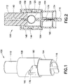
- FIG. 1 is a perspective view of an injection device 100 in accordance with an embodiment of the present invention.
- the injection device 100 includes a safety shield 104, a housing 108, and an injector member or injector button 112.
- the housing 108 is slidably connected with the safety shield 104.
- the injection device 100 also includes a removable needle shield 116.
- FIG 2 is a cross-sectional view illustrating the injection device 100 in an initial state.
- injection device 100 also includes a medicament container 120 with the needle 124 fixed thereto and a biasing member 128, such as a spring 128.
- the medicament container 120 includes a flexible blister 132 with a hub 136 for holding the needle 124.
- the needle 124 is in fluid connection with the flexible blister 132 via the hub 136.
- An example of such a medicament container is disclosed in U.S. No. 4,955,871 to Thomas .
- the medicament container 120 is fixedly connected with the housing 108.
- the medicament container includes a double ended needle that punctures a valve membrane when the needle shield is pushed rearward.
- FIG. 2 also illustrates that the injector button 112 includes an internal slot 140 axially aligned with the flexible blister 132.
- FIG. 2 illustrates that the housing 108 includes inner and outer walls 144 and 148.
- the biasing member 128 is disposed between the inner and outer walls 144 and 148 and the injector button 112 and the medicament container 120 are disposed radially within the inner wall 144.
- the injector button 112 is slidably disposed relative to the medicament container 120 and the inner wall 144.
- the inner wall 144 has a pair of detents, including an initial detent 152 and a locking detent 156.
- the detents 152 and 156 are circumferential recesses on an interior surface of the inner wall 144. According to another embodiment, the detents 152 and 156 are discontinuous circumferential recesses disposed on the interior surface of the inner wall 144.
- the injector button 112 includes a button projection 158 disposed at a distal end thereof and having a shape corresponding to the detents 152 and 156.
- the button projection 158 and the initial detent 152 interact to prevent proximal movement of the injector button 112 relative to the housing 108 subsequent to the button projection 158 engaging the initial detent 152.
- the button projection 158 and the locking detent 156 interact to prevent proximal movement of the injector button 112 relative to the housing 108 subsequent to the button projection 158 engaging the locking detent 156.
- the safety shield 104 is substantially cylindrical and has a depth stop 160 for limiting penetration of the needle 124 into a patient's skin.
- the safety shield 104 also includes a shield tab 164 radially projecting from a flange 168 disposed at a proximal end of the safety shield 104.
- the flange 168 provides a bearing surface for a distal end of the biasing member 128 and the shield tab 164 interacts with a guide groove 172 in the housing 108 to guide movement of the housing 108 relative to the safety shield 104.
- the distal end of the safety shield 104 defines a surface 170 for contacting a patient's skin.
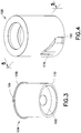
- the housing 108 includes a cantilevered upper flexible arm 176 and a cantilevered lower flexible arm 180.
- the upper flexible arm 176 and the lower flexible arm 180 are locking members of the guide groove 172.
- FIG. 5 is a cross-sectional view of the housing 108 taken along line 5-5 of FIG. 4 .
- the guide groove 172 includes first and second substantially axial portions 184 and 188 and a substantially helical portion 192 connecting the first and second axial portions 184 and 188.
- the substantially helical portion 192 cuts through the housing 108.
- the upper flexible arm 176 includes a ramp 194 disposed at the free end of an internal side thereof.
- the lower flexible arm 180 includes a ramp hook 196.
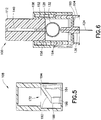
- FIGS. 6-8 are cross-sectional views illustrating operation of the injection device 100.
- a user To operate the device, a user first removes the needle shield 116 and places the surface 170 of the safety shield 104 on a patient's skin 194. Subsequently, the user depresses the injector button 112 to displace the medicament container to an injection position. The force required to compress the biasing member 128 and the force required to penetrate the user's skin with the needle 124 are less than that required to displace the button projection 158 from the initial detent 152.
- the housing 108 slides distally relative to the safety shield 104 and the needle 124 penetrates the user's skin 198, stopping at a predetermined depth when the hub 136 of the medicament container 120 contacts the depth stop 160, as shown in FIG. 6 .
- the shield tab 164 engages the first axial portion 184 of the guide groove 172 and travels proximally relative thereto.
- the engagement of the shield tab 164 and the first axial portion 184 constrains the displacement of the housing 108 relative to the safety shield 104 to be axial and prevents rotation of the housing 108 relative to the safety shield 104.
- the shield tab 164 passes the ramp 194 and radially displaces the free end of the upper flexible arm 176.
- the shield tab 164 completes passing the ramp 194 and reaches the proximal end of the first axial portion 184.
- the free end of the upper flexible arm 176 snaps back to form a portion of the helical portion 192 of the guide groove 172 and to prevent subsequent axial movement of the shield tab 164 in the first axial portion 184.
- the button projection 158 displaces from the initial detent 152 and the injector button 112 displaces distally relative to the inner wall 144 and the medicament container 120 until the button projection 158 engages the locking detent 156.
- the walls of the internal slot 140 engage and compress the flexible blister 132 and expel the medicament from the flexible blister 132 into the patient.
- the button projection 158 engages the locking detent 156 (defining an injection state)
- the corresponding shapes thereof prevent subsequent proximal displacement of the injector button 112 relative to the housing 108.
- the proximal end of the injector button 112 is disposed sufficiently close to the proximal end of the housing 108 that a user cannot gain a purchase on the injector button 112 to attempt proximal displacement of the injector button 112. According to one embodiment, once the medicament is injected, the proximal end of the injector button 112 is substantially flush with the proximal end of the housing 108.
- the user releases the injector button 112 and the biasing member 128 proximally displaces the housing 108 (as well as the medicament container 120 and the injector button 112) relative to the safety shield 104, thereby displacing the medicament container 120 (and the needle 124) to a withdrawn position. Because the shield tab 164 engages the helical portion 192 of the guide groove 172, the during a first portion of the proximal displacement, the housing 108 rotates until the shield tab 164 reaches the proximal end of the second axial portion 188.
- the biasing member 128 continues to proximally displace the housing 108 and the engagement of the shield tab 164 in the second axial portion 188 constrains the proximal displacement to be axial.
- the shield tab 164 passes the ramp hook 196 of the lower flexible arm 180 and radially displaces the free end of the lower flexible arm 180.
- the shield tab 164 completes passing the ramp hook 196 and reaches the distal end of the second axial portion 188.
- the free end of the lower flexible arm 180 snaps back to prevent subsequent axial movement of the shield tab 164 in the second axial portion 188.
- the free end of the lower flexible arm 180 locks the shield tab 164 and prevents subsequent displacement of the housing 108 relative to the safety shield 104, thereby fixing the injection device 100 in a post-injection safe state.
- FIG. 10 is a perspective view of an injection device 200 not according to the invention and FIG. 11 is a cross sectional view of the injection device 200.
- the injection device 200 includes a safety shield 204 and a housing 208.
- the injection device 200 also includes a removable needle shield.
- the housing 208 slidably connects to the safety shield 204.
- the injection device 200 also includes an injector member 212 (including a plunger 214 and a stopper 216) that slidably connects with a medicament container 220, which has a needle 224 affixed to a distal end thereof.
- the injection device 200 includes a biasing member 228 biasing the medicament container 220 proximally away from the safety shield 204.
- the needle 224 communicates with a medicament disposed within the medicament container 220.
- the medicament container 220 is displaceable relative to the safety shield 204 from an initial position (shown in FIG. 11 ), to an injection position (shown in FIG. 14 ), to a withdrawn position (shown in FIG. 16 ).
- the safety shield 204 (having a depth stop 232, a flange 236, and a shield tab 240) is substantially similar to the safety shield 104 described previously. Accordingly, further detailed description of the safety shield is omitted for brevity.
- FIG. 1 is a depth stop 232, a flange 236, and a shield tab 240
- FIG. 12 is a perspective view of the housing 208 illustrating that, like the housing 108, the housing 208 includes an upper flexible arm 244 and a lower flexible arm 248.
- FIG. 13 is a cross-sectional view of the housing 208 taken along line 13-13 of FIG. 12 , and illustrates that, also like the housing 108, the housing 208 includes a guide groove 252 that includes first and second axial portions 256 and 260, and a substantially helical portion 264 connecting the first and second axial portions 256 and 260.
- the upper flexible arm 244 is disposed on the first axial portion 256 and the lower flexible arm 248 is disposed on the second axial portion 260.
- the upper flexible arm 244 includes a ramp 268 disposed at a free end thereof and the lower flexible arm 248 includes a ramp hook 272 disposed at a free end thereof.
- the ramp 268 and the ramp hook 272 function substantially similarly to the ramp 194 and ramp 196 described previously. Accordingly, further detailed description of the ramp 268 and the ramp-hook 272 are omitted for brevity.
- the upper flexible arm 244 includes a locking protrusion 276 at a proximal end thereof for selectively preventing displacement of the housing 208 and the plunger 214 relative to the medicament container 220.
- the upper flexible arm 244 also has an unlocking ramp 280 disposed thereon.
- the unlocking ramp 280 interacts with the shield tab 240 to radially displace the free end of the upper flexible arm 244, to permit movement of the housing 208 relative to the medicament container 220.
- the upper flexible arm 244 has two portions.
- the locking protrusion 276 is disposed on a first portion
- the ramp 268 and the unlocking ramp 280 are disposed on a second portion, which also includes the first axial portion 256 of the guide groove 252.
- the locking protrusion 276 engages a radial flange 284 disposed at a proximal end of the medicament container 220.
- This engagement prevents displacement of the housing 208 and the plunger 214 relative to the medicament container 220.
- the radial flange 284 compresses the biasing member 228, and the housing 208, injector member 212, and the medicament container 220 distally displace as a unit relative to the safety shield 204 until the medicament container 220 reaches the depth stop 232, which is an injection state shown in FIG. 14 .
- This displacement of the medicament container 220 also drives the needle 224 to pierce the patient's skin.
- the shield tab 240 travels in the first axial portion 256 and engages the unlocking ramp 280 to radially displace a free end of the upper flexible arm 244, thereby disengaging the locking protrusion 276 from the radial flange 284. Accordingly, because the locking protrusion 276 no longer engages the radial flange 284, the housing 208 (as well as the stopper 216 and the plunger 214, which contacts the housing 208) is displaceable relative to the medicament container 220. Thus, as the user continues to apply force to the proximal end of the housing 208, as shown in FIG. 15 , the housing 208 and the injector member 212 displace distally relative to the medicament container 220, expelling the medicament from the medicament container 220.
- the shield tab 240 continues to travel proximally relative to the first axial portion 256 of the guide groove 252.
- the engagement of the shield tab 240 and the first axial portion 256 constrains the displacement of the housing 208 relative to the safety shield 204 to be axial and prevents rotation of the housing 208 relative to the safety shield 204.
- the shield tab 240 passes the ramp 268 and radially displaces the free end of the upper flexible arm 244.
- the shield tab 240 completes passing the ramp 268 and reaches the proximal end of the first axial portion 256.
- the free end of the upper flexible arm 244 snaps back to form a portion of the helical portion 264 of the guiding groove 252 and to prevent subsequent axial movement of the shield tab 240 in the first axial portion 256.
- the user releases the housing 208 and the biasing member 228 proximally displaces the housing 208 (as well as the medicament container 220 and the injector member 212) relative to the safety shield 204, thereby displacing the medicament container 220 (and the needle 224) to a withdrawn position. Because the shield tab 240 engages the helical portion 264 of the guide groove 252, during a first portion of the proximal displacement, the housing 208 rotates until the shield tab 240 reaches the proximal end of the second axial portion 260.
- the biasing member 228 continues to proximally displace the housing 208 and the engagement of the shield tab 240 in the second axial portion 260 constrains the proximal displacement of the housing 208 to be axial.
- the shield tab 240 passes the ramp hook 272 of the lower flexible arm 248 and radially displaces the free end of the lower flexible arm 248.
- the shield tab 240 completes passing the ramp hook 272 and reaches the distal end of the second axial portion 260.
- the free end of the lower flexible arm 248 snaps back to prevent subsequent axial movement of the shield tab 240 in the second axial portion 260.
- the free end of the lower flexible arm 248 locks the shield tab 240 and prevents subsequent displacement of the housing 208 relative to the safety shield 204, thereby fixing the injection device 200 in a post-injection safe state.
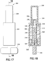
- FIG. 17 is a perspective view of an injection device 300 not according to the invention in an initial state and FIG. 18 is a cross-sectional view of the device 300.
- the injection device 300 includes a safety shield 304 with a surface 306 for contacting a patient's skin disposed at a distal end thereof, a medicament container 308 slidably connected to the safety shield 304, an inner housing 312 slidably connected to the safety shield 304, and a needle shield 316 for selectively covering a distal end of a needle 324.
- the medicament container 308 may be made of, for example, glass or plastic.
- the safety shield 304 includes a pair of locking tabs 318, which are biased radially inward.
- the injection device 300 also includes a needle hub 320 slidably connected to the inner housing 312.
- the double-ended needle 324 is affixed to the needle hub 320.
- the injection device 300 further includes a biasing member 328 disposed within the safety shield 304 and proximally biasing the medicament cartridge 308, and a stopper 332 slidably disposed in the medicament cartridge 308.
- the inner housing 312 has a barb 334 at the proximal end thereof engaged with a corresponding recess 338 in the distal end of the stopper 332, to fix the stopper 332 to the inner housing 312.
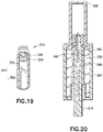
- the needle hub 320 has a radial protrusion 336 disposed at a proximal end thereof and the inner housing 312 includes a pair of detents or receiving grooves 340 (shown in FIG. 19 ) corresponding to the radial protrusion 336.
- the radial protrusion 336 and the receiving grooves 340 are circumferential.
- the needle hub 320 is movable from a first position, in which the radial protrusion 336 is disposed in a distal one of the receiving groove 340, to a second position, in which the radial protrusion 336 is disposed in a proximal one of the receiving grooves 340.
- the inner housing 312 also includes a pair of cam tracks 344 that slidably receive a pair of cam tabs 348 of the needle shield 316.
- each cam track 344 includes a first, substantially helical portion 352 and a second, substantially linear portion 356.
- the cam tabs 348 travel along the helical portions 352 until reaching the end of the helical portions 352 (and the beginning of the linear portions 356).
- This rotation of the needle shield 316 proximally displaces the needle hub 320 from the first position to the second position and pierces the stopper 332 with the proximal end of the needle 324, as shown in FIG. 20 .
- the user distally displaces the needle shield 316 to remove it from the injection device 300.
- the injection device 300 as shown in FIG. 21 , is now ready for injection.
- the user places the injection device 300 so that the surface 306 of the safety shield 304 contacts the user's skin and presses down on the medicament container 308, compressing the biasing member 328.
- the combination of forces of the back pressure of the medicament in the medicament container 308 and the friction between the stopper 332 and the medicament container 308 is greater than the combination of the force from the biasing member 328 and the force required for the needle 324 to pierce the patient's skin, so that upon distal displacement of the medicament container 308, the needle 324 pierces the patient's skin prior to dispensing of the medicament.
- This downward pressure on the medicament container 308 drives the needle 324 into the patient's skin until the inner housing 312 contacts the patient's skin, as shown in FIG. 22 .
- the proximal end of the medicament container 308 is substantially flush with the proximal end of the safety shield 304.
- the user releases the medicament container 308, and the force of the biasing member 328 proximally displaces the medicament container 308 (as well as the inner housing 312 and the needle 324).
- the locking tabs 318 snap radially inward due to their radially inward bias. In this position, as shown in FIG. 24 , the locking tabs 318 prevent subsequent distal displacement of the inner housing 312 therepast, and thus, prevent re-use of the injection device 300.
- Embodiments of the present invention are user-friendly, and can hide the needle prior to injection, thereby making it less intimidating to users who might be unaccustomed to injections. Additionally, in embodiments of the present invention, the needle insertion and injection stroke can be achieved in one single motion. Further, the needle can be automatically shielded once the device is removed from the skin in embodiments of the present invention. Moreover, the compact size and low parts count of embodiments of the present invention can reduce manufacturing costs as well as transportation and storage costs.
- embodiments of the present invention can be achieved by eliminating some of the higher-order features of such auto injectors.
- embodiments of the present invention do not require automatic, spring-loaded pushing mechanisms that make an autoinjector "automatic.” Instead, users can apply the necessary force.
- embodiments of the present invention can have a force-based detent that the user needs to overcome before the injection can begin. Once the detent is overcome, the needle assembly snaps into the skin and then the injection begins.
- other features can also be eliminated, such as an activation button, and a spring-loaded safety device that only allows the injector to be triggered once it is pushed against an object.
Landscapes
- Health & Medical Sciences (AREA)
- Engineering & Computer Science (AREA)
- Hematology (AREA)
- Anesthesiology (AREA)
- Biomedical Technology (AREA)
- Heart & Thoracic Surgery (AREA)
- Vascular Medicine (AREA)
- Life Sciences & Earth Sciences (AREA)
- Animal Behavior & Ethology (AREA)
- General Health & Medical Sciences (AREA)
- Public Health (AREA)
- Veterinary Medicine (AREA)
- Environmental & Geological Engineering (AREA)
- Infusion, Injection, And Reservoir Apparatuses (AREA)
Claims (3)
- Injektionsvorrichtung (100), die umfasst:eine Sicherheitsabschirmung (104), die ein erstes Ende und eine Fläche, die an einem zweiten Ende derselben angeordnet ist, zum Kontaktieren der Haut eines Patienten aufweist, wobei die Sicherheitsabschirmung einen Abschirmungsansatz (164), der von dieser absteht, aufweist;ein Gehäuse (108), das bezüglich der Sicherheitsabschirmung gleitfähig angeordnet ist, wobei das Gehäuse eine Führungsnut (172) zum Zusammengreifen mit dem Abschirmungsansatz zum Führen einer Bewegung des Gehäuses relativ zu der Sicherheitsabschirmung aufweist, wobei die Führungsnut einen ersten und einen zweiten axialen Abschnitt (184, 188) und einen im Wesentlichen schraubenförmigen Abschnitt (192), der den ersten und den zweiten axialen Abschnitt verbindet, aufweist;einen Medikamentenbehälter (120), der mit dem Gehäuse verbunden ist und an dem eine Nadel (124) befestigt ist, die mit einem Medikament in Verbindung steht, das in dem Medikamentenbehälter (120) angeordnet ist, wobei der Medikamentenbehälter (120) relativ zu der Sicherheitsabschirmung von einer Anfangsposition in eine Injektionsposition zu einer Rückzugsposition verschiebbar ist;ein Vorspannelement (128), das den Medikamentenbehälter (120) von der Sicherheitsabschirmung weg vorspannt; undein Injektorelement (112), das relativ zu dem Medikamentenbehälter (120) gleitfähig angeordnet ist zum Austreiben des Medikaments aus dem Medikamentenbehälter (120);dadurch gekennzeichnet, dassder Medikamentenbehälter (120) fest mit dem Gehäuse verbunden ist;das Gehäuse eine Innenwand (144) und eine Außenwand (148) aufweist;das Vorspannelement (128) zwischen der Innen- und der Außenwand angeordnet ist; und der Medikamentenbehälter (120) radial innerhalb der Innenwand angeordnet ist.
- Injektionsvorrichtung nach Anspruch 1, bei der:der Medikamentenbehälter (120) einen flexiblen Blister (132) umfasst;das Injektorelement einen Injektorknopf (112) umfasst, der einen internen Schlitz (140) aufweist, welcher axial mit dem flexiblen Blister ausgerichtet ist; undwenn der Injektorknopf (112) gedrückt wird, die Wände des internen Schlitzes den flexiblen Blister (132) zusammendrücken, um das Medikament aus dem Medikamentenbehälter (120) auszutreiben.
- Injektionsvorrichtung nach Anspruch 1, bei der:eines des Injektorelements (112) und der Innenwand (144) einen radialen Vorsprung (158) aufweist und das andere des Injektorelements und der Innenwand ein Paar von Nuten (152, 156) zum selektiven Festhalten des radialen Vorsprungs und Verhindern einer proximalen Translation des Injektorelements daran vorbei aufweist; undeine erste des Paars von Nuten einem Anfangszustand entspricht und die andere des Paars von Nuten einem Injektionszustand entspricht.
Priority Applications (3)
| Application Number | Priority Date | Filing Date | Title |
|---|---|---|---|
| EP15170527.4A EP2942072B1 (de) | 2011-05-18 | 2011-05-18 | Kostengünstiger einweginjektor |
| ES15170527T ES2713007T3 (es) | 2011-05-18 | 2011-05-18 | Inyector de un único uso de bajo coste |
| DK15170527.4T DK2942072T3 (en) | 2011-05-18 | 2011-05-18 | LOW PRICE SINGLE INJECTION FITTING |
Applications Claiming Priority (3)
| Application Number | Priority Date | Filing Date | Title |
|---|---|---|---|
| PCT/US2011/000876 WO2012158135A1 (en) | 2011-05-18 | 2011-05-18 | Single-use injector of low cost |
| EP15170527.4A EP2942072B1 (de) | 2011-05-18 | 2011-05-18 | Kostengünstiger einweginjektor |
| EP11865807.9A EP2709694B1 (de) | 2011-05-18 | 2011-05-18 | Kostengünstiger einweginjektor |
Related Parent Applications (2)
| Application Number | Title | Priority Date | Filing Date |
|---|---|---|---|
| EP11865807.9A Division EP2709694B1 (de) | 2011-05-18 | 2011-05-18 | Kostengünstiger einweginjektor |
| EP11865807.9A Division-Into EP2709694B1 (de) | 2011-05-18 | 2011-05-18 | Kostengünstiger einweginjektor |
Publications (2)
| Publication Number | Publication Date |
|---|---|
| EP2942072A1 EP2942072A1 (de) | 2015-11-11 |
| EP2942072B1 true EP2942072B1 (de) | 2018-11-28 |
Family
ID=47177212
Family Applications (2)
| Application Number | Title | Priority Date | Filing Date |
|---|---|---|---|
| EP15170527.4A Active EP2942072B1 (de) | 2011-05-18 | 2011-05-18 | Kostengünstiger einweginjektor |
| EP11865807.9A Active EP2709694B1 (de) | 2011-05-18 | 2011-05-18 | Kostengünstiger einweginjektor |
Family Applications After (1)
| Application Number | Title | Priority Date | Filing Date |
|---|---|---|---|
| EP11865807.9A Active EP2709694B1 (de) | 2011-05-18 | 2011-05-18 | Kostengünstiger einweginjektor |
Country Status (10)
| Country | Link |
|---|---|
| US (1) | US9656027B2 (de) |
| EP (2) | EP2942072B1 (de) |
| JP (1) | JP5833229B2 (de) |
| CN (2) | CN106039478B (de) |
| BR (1) | BR112013029579B1 (de) |
| CA (4) | CA2978589C (de) |
| DK (2) | DK2709694T3 (de) |
| ES (2) | ES2713007T3 (de) |
| MX (4) | MX350958B (de) |
| WO (1) | WO2012158135A1 (de) |
Families Citing this family (48)
| Publication number | Priority date | Publication date | Assignee | Title |
|---|---|---|---|---|
| BR112012024238A2 (pt) | 2010-03-25 | 2019-09-24 | New Injection Systems Ltd | injetor |
| US8920385B2 (en) | 2010-05-05 | 2014-12-30 | Safety Syringes, Inc. | Extended finger flange for syringe systems |
| GB201206766D0 (en) * | 2012-04-17 | 2012-05-30 | Univ Antwerpen | Prefillable intradermal delivery device |
| CA2890764C (en) | 2012-11-23 | 2021-05-04 | New Injection Systems Ltd | Auto-injector assembly |
| US9480782B2 (en) * | 2013-01-14 | 2016-11-01 | R. Ashley Burrow | Surgical aspiration and irrigation |
| US12239822B2 (en) | 2013-03-15 | 2025-03-04 | Windgap Medical, Inc. | Portable drug mixing and delivery device and associated methods |
| US10569017B2 (en) | 2013-03-15 | 2020-02-25 | Windgap Medical, Inc. | Portable drug mixing and delivery device and associated methods |
| US20150367073A1 (en) | 2013-03-15 | 2015-12-24 | Windgap Medical, Llc | Portable Drug Mixing and Delivery Device and Associated Methods |
| US9907910B2 (en) | 2013-03-15 | 2018-03-06 | Windgap Medical, Inc. | Portable drug mixing and delivery device and associated methods |
| JP6560187B2 (ja) | 2013-03-15 | 2019-08-14 | ウインドギャップ メディカル インコーポレイテッド | 携帯型薬剤混合及び送達システム並びに方法 |
| EP3082419A4 (de) | 2013-12-18 | 2017-09-20 | Windgap Medical, Inc. | Arzneimittelmisch- und -ausgabesystem und -verfahren |
| CN111228117B (zh) * | 2014-04-21 | 2024-01-12 | 贝克顿迪金森有限公司 | 流体传送装置和用于该装置的包装件 |
| JP2017519581A (ja) * | 2014-06-27 | 2017-07-20 | ノボ・ノルデイスク・エー/エス | 針シールドトリガー部を有する自動注射器 |
| JP6344817B2 (ja) * | 2014-07-31 | 2018-06-20 | 三菱鉛筆株式会社 | 注射針保護装置 |
| US11116903B2 (en) | 2014-08-18 | 2021-09-14 | Windgap Medical, Inc | Compression seal for use with a liquid component storage vial of an auto-injector |
| CA2971440C (en) | 2014-12-18 | 2024-02-13 | Windgap Medical, Inc. | Method and compositions for dissolving or solubilizing therapeutic agents |
| CN111150907B (zh) * | 2015-01-26 | 2022-08-19 | 生物研究与发展公司 | 制造预装填胶接针头式注射器的制造方法 |
| US10518023B2 (en) * | 2015-04-28 | 2019-12-31 | Novo Nordisk A/S | Medical injection device with telescopically movable needle shield having a cleaning chamber for the needle |
| US10220147B2 (en) | 2015-08-13 | 2019-03-05 | Windgap Medical, Inc. | Mixing and injection device with sterility features |
| EP3173113A1 (de) | 2015-11-27 | 2017-05-31 | Sanofi-Aventis Deutschland GmbH | Injektionsnadelanordnung |
| JP6924189B2 (ja) | 2015-11-27 | 2021-08-25 | サノフィ−アベンティス・ドイチュラント・ゲゼルシャフト・ミット・ベシュレンクテル・ハフツング | 薬剤注射デバイス |
| EP3380149B1 (de) | 2015-11-27 | 2019-11-06 | Sanofi-Aventis Deutschland GmbH | Wirkstoffabgabevorrichtung mit kappe |
| GB2546502A (en) * | 2016-01-19 | 2017-07-26 | Owen Mumford Ltd | Safety syringe apparatus |
| ES2984486T3 (es) | 2016-04-01 | 2024-10-29 | Idevax Bv | Dispositivo de inyección |
| USD819198S1 (en) | 2016-04-28 | 2018-05-29 | Amgen Inc. | Autoinjector with removable cap |
| EP3484551B1 (de) * | 2016-07-14 | 2025-11-26 | Sanofi-Aventis Deutschland GmbH | Wirkstoffabgabevorrichtung mit kappe |
| FR3056916B1 (fr) * | 2016-10-04 | 2018-11-09 | Aptar France Sas | Dispositif d'injection manuelle. |
| CN111511427B (zh) * | 2017-12-28 | 2023-01-06 | 赛诺菲 | 用于附接到注射装置的传感器装置 |
| JP7458140B2 (ja) * | 2018-02-09 | 2024-03-29 | ニプロ株式会社 | 薬液注入装置 |
| US12383467B2 (en) | 2018-07-10 | 2025-08-12 | Becton, Dickinson And Company | Syringe assembly |
| CN112867520B (zh) * | 2018-09-04 | 2023-04-07 | 阿莱尔杰有限公司 | 自动注射医疗装置系统 |
| CN109199550B (zh) * | 2018-10-18 | 2023-08-18 | 颜斌 | 一种疝气微创手术治疗针 |
| US12186544B2 (en) * | 2019-03-29 | 2025-01-07 | Becton, Dickinson And Company | Injection assembly with movable sleeve |
| USD1010811S1 (en) | 2019-09-30 | 2024-01-09 | Amgen Inc. | Handheld drug delivery device |
| USD1030041S1 (en) | 2020-01-14 | 2024-06-04 | Amgen Inc. | Handheld drug delivery device |
| USD1030040S1 (en) | 2020-01-14 | 2024-06-04 | Amgen Inc. | Handheld drug delivery device |
| CA3172305C (en) | 2020-03-25 | 2023-02-07 | Joseph B. Hoffer | Apparatuses and methods for injecting medicaments |
| JP2023541328A (ja) * | 2020-10-11 | 2023-09-29 | エル.ジー.ピー. テクノロジー ホールディングス リミティッド ライアビリティ カンパニー | 注射送達装置 |
| USD973866S1 (en) | 2020-11-05 | 2022-12-27 | Amgen Inc. | Handheld drug delivery device |
| USD974547S1 (en) | 2020-11-05 | 2023-01-03 | Amgen Inc. | Handheld drug delivery device |
| JP2021500644S (ja) | 2020-11-05 | 2022-12-27 | 注射器 | |
| USD985117S1 (en) | 2021-03-10 | 2023-05-02 | Amgen Inc. | Handheld drug delivery device |
| USD985116S1 (en) | 2021-03-10 | 2023-05-02 | Amgen Inc. | Handheld drug delivery device |
| USD985118S1 (en) | 2021-03-10 | 2023-05-02 | Amgen Inc. | Handheld drug delivery device |
| USD985119S1 (en) | 2021-03-30 | 2023-05-02 | Amgen Inc. | Handheld drug delivery device |
| JP7525955B2 (ja) | 2021-04-08 | 2024-07-31 | ラブ ライフサイエンシズ エルエルシー | プレフィルドシリンジ安全デバイスおよび注射器 |
| WO2022243082A1 (en) * | 2021-05-21 | 2022-11-24 | Shl Medical Ag | Medicament delivery device |
| WO2025071724A1 (en) * | 2023-09-27 | 2025-04-03 | West Pharmaceutical Services, Inc. | Precision needle advancement |
Family Cites Families (27)
| Publication number | Priority date | Publication date | Assignee | Title |
|---|---|---|---|---|
| GB989185A (en) | 1961-08-25 | 1965-04-14 | Glaxo Group Ltd | Improvements in or relating to hypodermic syringes |
| NL6611226A (de) | 1966-08-10 | 1968-02-12 | ||
| FR2439020A1 (fr) | 1978-10-17 | 1980-05-16 | Freisz Jean | Systeme porte-aiguille pour ampoule auto-injectable |
| US4883473A (en) | 1987-04-29 | 1989-11-28 | Path | Single use injection device |
| US4955871A (en) | 1987-04-29 | 1990-09-11 | Path | Single-use disposable syringe |
| GB9200219D0 (en) * | 1992-01-07 | 1992-02-26 | Medimech Int Ltd | Automatic injectors |
| JP3785186B2 (ja) | 1992-01-07 | 2006-06-14 | エスティーアイ インターナショナル リミテッド | 自動式注射器 |
| EP0768902B1 (de) | 1992-11-19 | 1998-07-15 | Tebro S.A. | Automatische injektionsvorrichtung für vorgefüllte spritzen |
| US5984899A (en) | 1993-02-11 | 1999-11-16 | Beech Medical Products, Inc. | Needle protector device having a lockable protective cover which is unlockable during actuation |
| DE69427226T2 (de) | 1993-03-24 | 2001-08-30 | Owen Mumford Ltd., Woodstock | Vorrichtung zur injektion |
| US5634906A (en) | 1995-12-27 | 1997-06-03 | Habley Medical Technology Corporation | Needle hiding shield for a dose metering syringe |
| US5688241A (en) * | 1996-04-15 | 1997-11-18 | Asbaghi; Hooman Ali | Automatic non-reusable needle guard |
| GB9612724D0 (en) | 1996-06-18 | 1996-08-21 | Owen Mumford Ltd | Improvements relating to injection devices |
| US6569115B1 (en) * | 1997-08-28 | 2003-05-27 | Mdc Investment Holdings, Inc. | Pre-filled retractable needle injection device |
| DE19755125B4 (de) | 1997-12-11 | 2006-04-20 | Tecpharma Licensing Ag | Nadelschutzvorrichtung für Injektionsgeräte |
| ES2683629T3 (es) * | 2001-04-13 | 2018-09-27 | Becton, Dickinson And Company | Dispositivo de administración intradérmica de llenado previo con aguja oculta y protección pasiva |
| GB0119520D0 (en) * | 2001-08-10 | 2001-10-03 | Owen Mumford Ltd | Improvements relating to injection devices |
| US6808507B2 (en) | 2002-05-10 | 2004-10-26 | Cambridge Biostability Ltd. | Safety injectors |
| DE602004013140T2 (de) | 2003-05-08 | 2009-07-02 | Novo Nordisk A/S | Interne nadeleinführvorrichtung |
| ES2296129T3 (es) | 2004-01-23 | 2008-04-16 | The Medical House Plc | Dispositivo de inyeccion. |
| GB2410188B (en) * | 2004-01-23 | 2006-01-25 | Medical House Plc | Injection device |
| WO2005079441A2 (en) | 2004-02-17 | 2005-09-01 | Children's Hospital Medical Center | Injection device for administering a vaccine |
| FR2884723B1 (fr) * | 2005-04-20 | 2008-03-14 | Becton Dickinson France Soc Pa | Dispositif de protection d'un dispositif d'injection |
| US7462168B2 (en) * | 2007-01-23 | 2008-12-09 | Becton, Dickinson And Company | Safety pen needle with passive safety shield system |
| WO2009040602A1 (en) * | 2007-09-25 | 2009-04-02 | Becton Dickinson France | Autoinject0r with deactivating means moveable by a safety shield |
| ES2914825T3 (es) * | 2008-08-15 | 2022-06-16 | Becton Dickinson Co | Conjunto de aguja de pluma de seguridad |
| WO2010035056A1 (en) | 2008-09-29 | 2010-04-01 | Becton Dickinson France | Automatic injection device with sensitive indicator of completed injection |
-
2011
- 2011-05-18 EP EP15170527.4A patent/EP2942072B1/de active Active
- 2011-05-18 CN CN201610458283.3A patent/CN106039478B/zh active Active
- 2011-05-18 BR BR112013029579-1A patent/BR112013029579B1/pt active IP Right Grant
- 2011-05-18 CA CA2978589A patent/CA2978589C/en active Active
- 2011-05-18 CA CA2978588A patent/CA2978588C/en active Active
- 2011-05-18 DK DK11865807.9T patent/DK2709694T3/en active
- 2011-05-18 DK DK15170527.4T patent/DK2942072T3/en active
- 2011-05-18 US US14/117,846 patent/US9656027B2/en active Active
- 2011-05-18 EP EP11865807.9A patent/EP2709694B1/de active Active
- 2011-05-18 ES ES15170527T patent/ES2713007T3/es active Active
- 2011-05-18 CA CA2836232A patent/CA2836232C/en active Active
- 2011-05-18 MX MX2016010120A patent/MX350958B/es unknown
- 2011-05-18 WO PCT/US2011/000876 patent/WO2012158135A1/en not_active Ceased
- 2011-05-18 MX MX2013013309A patent/MX346965B/es active IP Right Grant
- 2011-05-18 JP JP2014511325A patent/JP5833229B2/ja active Active
- 2011-05-18 MX MX2017000336A patent/MX370263B/es unknown
- 2011-05-18 CN CN201180071887.8A patent/CN103619381B/zh active Active
- 2011-05-18 MX MX2016010119A patent/MX353902B/es unknown
- 2011-05-18 CA CA3005126A patent/CA3005126C/en active Active
- 2011-05-18 ES ES11865807.9T patent/ES2674180T3/es active Active
Non-Patent Citations (1)
| Title |
|---|
| None * |
Also Published As
| Publication number | Publication date |
|---|---|
| CN103619381A (zh) | 2014-03-05 |
| EP2709694A4 (de) | 2014-12-03 |
| US9656027B2 (en) | 2017-05-23 |
| CA2978589A1 (en) | 2012-11-22 |
| BR112013029579A2 (pt) | 2016-12-06 |
| CA2836232C (en) | 2019-03-12 |
| ES2713007T3 (es) | 2019-05-17 |
| WO2012158135A1 (en) | 2012-11-22 |
| CN106039478A (zh) | 2016-10-26 |
| CA3005126A1 (en) | 2012-11-22 |
| CN103619381B (zh) | 2016-08-17 |
| MX346965B (es) | 2017-04-07 |
| JP2014516687A (ja) | 2014-07-17 |
| CA3005126C (en) | 2019-12-24 |
| DK2709694T3 (en) | 2018-06-25 |
| CA2978588A1 (en) | 2012-11-22 |
| EP2709694B1 (de) | 2018-03-21 |
| MX370263B (es) | 2019-12-09 |
| US20140088512A1 (en) | 2014-03-27 |
| EP2709694A1 (de) | 2014-03-26 |
| EP2942072A1 (de) | 2015-11-11 |
| MX2013013309A (es) | 2014-02-27 |
| CA2978589C (en) | 2019-10-01 |
| MX353902B (es) | 2018-02-02 |
| BR112013029579B1 (pt) | 2021-02-23 |
| DK2942072T3 (en) | 2019-03-11 |
| JP5833229B2 (ja) | 2015-12-16 |
| CN106039478B (zh) | 2019-08-13 |
| MX350958B (es) | 2017-09-27 |
| CA2836232A1 (en) | 2012-11-22 |
| ES2674180T3 (es) | 2018-06-27 |
| CA2978588C (en) | 2019-12-31 |
Similar Documents
| Publication | Publication Date | Title |
|---|---|---|
| CA2978589C (en) | Single-use injector of low cost | |
| AU2019213383B2 (en) | An auto-injector for epinephrine injection | |
| EP2405962B1 (de) | Vorrichtung zur injizierung eines arzneimittels mit automatischem zurückziehen der spritze nach der injektion | |
| CN106860975B (zh) | 注射装置 | |
| US20200108211A1 (en) | Auto injector with recap prevention | |
| MX2013000069A (es) | Dispositivo de seguridad para una jeringa precargada y dispositivo de inyeccion. | |
| US20250001079A1 (en) | Autoinjector | |
| JP6080914B2 (ja) | 低コストの単回使用注射器 | |
| JP6118848B2 (ja) | 低コストの単回使用注射器 | |
| JP2024538253A (ja) | 自動注射器の解除機構 | |
| CN121314008A (zh) | 具有单个驱动弹簧的可重复使用的自动注射装置 |
Legal Events
| Date | Code | Title | Description |
|---|---|---|---|
| PUAI | Public reference made under article 153(3) epc to a published international application that has entered the european phase |
Free format text: ORIGINAL CODE: 0009012 |
|
| AC | Divisional application: reference to earlier application |
Ref document number: 2709694 Country of ref document: EP Kind code of ref document: P |
|
| AK | Designated contracting states |
Kind code of ref document: A1 Designated state(s): AL AT BE BG CH CY CZ DE DK EE ES FI FR GB GR HR HU IE IS IT LI LT LU LV MC MK MT NL NO PL PT RO RS SE SI SK SM TR |
|
| 17P | Request for examination filed |
Effective date: 20160506 |
|
| RBV | Designated contracting states (corrected) |
Designated state(s): AL AT BE BG CH CY CZ DE DK EE ES FI FR GB GR HR HU IE IS IT LI LT LU LV MC MK MT NL NO PL PT RO RS SE SI SK SM TR |
|
| RAP1 | Party data changed (applicant data changed or rights of an application transferred) |
Owner name: BECTON, DICKINSON AND COMPANY |
|
| STAA | Information on the status of an ep patent application or granted ep patent |
Free format text: STATUS: EXAMINATION IS IN PROGRESS |
|
| 17Q | First examination report despatched |
Effective date: 20170421 |
|
| GRAP | Despatch of communication of intention to grant a patent |
Free format text: ORIGINAL CODE: EPIDOSNIGR1 |
|
| STAA | Information on the status of an ep patent application or granted ep patent |
Free format text: STATUS: GRANT OF PATENT IS INTENDED |
|
| INTG | Intention to grant announced |
Effective date: 20180608 |
|
| GRAS | Grant fee paid |
Free format text: ORIGINAL CODE: EPIDOSNIGR3 |
|
| GRAA | (expected) grant |
Free format text: ORIGINAL CODE: 0009210 |
|
| STAA | Information on the status of an ep patent application or granted ep patent |
Free format text: STATUS: THE PATENT HAS BEEN GRANTED |
|
| AC | Divisional application: reference to earlier application |
Ref document number: 2709694 Country of ref document: EP Kind code of ref document: P |
|
| AK | Designated contracting states |
Kind code of ref document: B1 Designated state(s): AL AT BE BG CH CY CZ DE DK EE ES FI FR GB GR HR HU IE IS IT LI LT LU LV MC MK MT NL NO PL PT RO RS SE SI SK SM TR |
|
| REG | Reference to a national code |
Ref country code: CH Ref legal event code: EP |
|
| REG | Reference to a national code |
Ref country code: CH Ref legal event code: NV Representative=s name: ISLER AND PEDRAZZINI AG, CH |
|
| REG | Reference to a national code |
Ref country code: AT Ref legal event code: REF Ref document number: 1069502 Country of ref document: AT Kind code of ref document: T Effective date: 20181215 |
|
| REG | Reference to a national code |
Ref country code: DE Ref legal event code: R096 Ref document number: 602011054423 Country of ref document: DE |
|
| REG | Reference to a national code |
Ref country code: IE Ref legal event code: FG4D |
|
| REG | Reference to a national code |
Ref country code: DK Ref legal event code: T3 Effective date: 20190304 |
|
| REG | Reference to a national code |
Ref country code: NL Ref legal event code: FP |
|
| REG | Reference to a national code |
Ref country code: SE Ref legal event code: TRGR |
|
| REG | Reference to a national code |
Ref country code: LT Ref legal event code: MG4D |
|
| REG | Reference to a national code |
Ref country code: AT Ref legal event code: MK05 Ref document number: 1069502 Country of ref document: AT Kind code of ref document: T Effective date: 20181128 |
|
| PG25 | Lapsed in a contracting state [announced via postgrant information from national office to epo] |
Ref country code: FI Free format text: LAPSE BECAUSE OF FAILURE TO SUBMIT A TRANSLATION OF THE DESCRIPTION OR TO PAY THE FEE WITHIN THE PRESCRIBED TIME-LIMIT Effective date: 20181128 Ref country code: IS Free format text: LAPSE BECAUSE OF FAILURE TO SUBMIT A TRANSLATION OF THE DESCRIPTION OR TO PAY THE FEE WITHIN THE PRESCRIBED TIME-LIMIT Effective date: 20190328 Ref country code: LT Free format text: LAPSE BECAUSE OF FAILURE TO SUBMIT A TRANSLATION OF THE DESCRIPTION OR TO PAY THE FEE WITHIN THE PRESCRIBED TIME-LIMIT Effective date: 20181128 Ref country code: BG Free format text: LAPSE BECAUSE OF FAILURE TO SUBMIT A TRANSLATION OF THE DESCRIPTION OR TO PAY THE FEE WITHIN THE PRESCRIBED TIME-LIMIT Effective date: 20190228 Ref country code: HR Free format text: LAPSE BECAUSE OF FAILURE TO SUBMIT A TRANSLATION OF THE DESCRIPTION OR TO PAY THE FEE WITHIN THE PRESCRIBED TIME-LIMIT Effective date: 20181128 Ref country code: LV Free format text: LAPSE BECAUSE OF FAILURE TO SUBMIT A TRANSLATION OF THE DESCRIPTION OR TO PAY THE FEE WITHIN THE PRESCRIBED TIME-LIMIT Effective date: 20181128 Ref country code: NO Free format text: LAPSE BECAUSE OF FAILURE TO SUBMIT A TRANSLATION OF THE DESCRIPTION OR TO PAY THE FEE WITHIN THE PRESCRIBED TIME-LIMIT Effective date: 20190228 Ref country code: AT Free format text: LAPSE BECAUSE OF FAILURE TO SUBMIT A TRANSLATION OF THE DESCRIPTION OR TO PAY THE FEE WITHIN THE PRESCRIBED TIME-LIMIT Effective date: 20181128 |
|
| REG | Reference to a national code |
Ref country code: ES Ref legal event code: FG2A Ref document number: 2713007 Country of ref document: ES Kind code of ref document: T3 Effective date: 20190517 |
|
| PG25 | Lapsed in a contracting state [announced via postgrant information from national office to epo] |
Ref country code: PT Free format text: LAPSE BECAUSE OF FAILURE TO SUBMIT A TRANSLATION OF THE DESCRIPTION OR TO PAY THE FEE WITHIN THE PRESCRIBED TIME-LIMIT Effective date: 20190328 Ref country code: AL Free format text: LAPSE BECAUSE OF FAILURE TO SUBMIT A TRANSLATION OF THE DESCRIPTION OR TO PAY THE FEE WITHIN THE PRESCRIBED TIME-LIMIT Effective date: 20181128 Ref country code: GR Free format text: LAPSE BECAUSE OF FAILURE TO SUBMIT A TRANSLATION OF THE DESCRIPTION OR TO PAY THE FEE WITHIN THE PRESCRIBED TIME-LIMIT Effective date: 20190301 Ref country code: RS Free format text: LAPSE BECAUSE OF FAILURE TO SUBMIT A TRANSLATION OF THE DESCRIPTION OR TO PAY THE FEE WITHIN THE PRESCRIBED TIME-LIMIT Effective date: 20181128 |
|
| PG25 | Lapsed in a contracting state [announced via postgrant information from national office to epo] |
Ref country code: CZ Free format text: LAPSE BECAUSE OF FAILURE TO SUBMIT A TRANSLATION OF THE DESCRIPTION OR TO PAY THE FEE WITHIN THE PRESCRIBED TIME-LIMIT Effective date: 20181128 Ref country code: PL Free format text: LAPSE BECAUSE OF FAILURE TO SUBMIT A TRANSLATION OF THE DESCRIPTION OR TO PAY THE FEE WITHIN THE PRESCRIBED TIME-LIMIT Effective date: 20181128 |
|
| REG | Reference to a national code |
Ref country code: DE Ref legal event code: R097 Ref document number: 602011054423 Country of ref document: DE |
|
| PG25 | Lapsed in a contracting state [announced via postgrant information from national office to epo] |
Ref country code: SK Free format text: LAPSE BECAUSE OF FAILURE TO SUBMIT A TRANSLATION OF THE DESCRIPTION OR TO PAY THE FEE WITHIN THE PRESCRIBED TIME-LIMIT Effective date: 20181128 Ref country code: RO Free format text: LAPSE BECAUSE OF FAILURE TO SUBMIT A TRANSLATION OF THE DESCRIPTION OR TO PAY THE FEE WITHIN THE PRESCRIBED TIME-LIMIT Effective date: 20181128 Ref country code: EE Free format text: LAPSE BECAUSE OF FAILURE TO SUBMIT A TRANSLATION OF THE DESCRIPTION OR TO PAY THE FEE WITHIN THE PRESCRIBED TIME-LIMIT Effective date: 20181128 Ref country code: SM Free format text: LAPSE BECAUSE OF FAILURE TO SUBMIT A TRANSLATION OF THE DESCRIPTION OR TO PAY THE FEE WITHIN THE PRESCRIBED TIME-LIMIT Effective date: 20181128 |
|
| PLBE | No opposition filed within time limit |
Free format text: ORIGINAL CODE: 0009261 |
|
| STAA | Information on the status of an ep patent application or granted ep patent |
Free format text: STATUS: NO OPPOSITION FILED WITHIN TIME LIMIT |
|
| PG25 | Lapsed in a contracting state [announced via postgrant information from national office to epo] |
Ref country code: SI Free format text: LAPSE BECAUSE OF FAILURE TO SUBMIT A TRANSLATION OF THE DESCRIPTION OR TO PAY THE FEE WITHIN THE PRESCRIBED TIME-LIMIT Effective date: 20181128 |
|
| 26N | No opposition filed |
Effective date: 20190829 |
|
| PG25 | Lapsed in a contracting state [announced via postgrant information from national office to epo] |
Ref country code: MC Free format text: LAPSE BECAUSE OF FAILURE TO SUBMIT A TRANSLATION OF THE DESCRIPTION OR TO PAY THE FEE WITHIN THE PRESCRIBED TIME-LIMIT Effective date: 20181128 |
|
| PG25 | Lapsed in a contracting state [announced via postgrant information from national office to epo] |
Ref country code: LU Free format text: LAPSE BECAUSE OF NON-PAYMENT OF DUE FEES Effective date: 20190518 |
|
| PG25 | Lapsed in a contracting state [announced via postgrant information from national office to epo] |
Ref country code: TR Free format text: LAPSE BECAUSE OF FAILURE TO SUBMIT A TRANSLATION OF THE DESCRIPTION OR TO PAY THE FEE WITHIN THE PRESCRIBED TIME-LIMIT Effective date: 20181128 |
|
| PG25 | Lapsed in a contracting state [announced via postgrant information from national office to epo] |
Ref country code: IE Free format text: LAPSE BECAUSE OF NON-PAYMENT OF DUE FEES Effective date: 20190518 |
|
| PG25 | Lapsed in a contracting state [announced via postgrant information from national office to epo] |
Ref country code: CY Free format text: LAPSE BECAUSE OF FAILURE TO SUBMIT A TRANSLATION OF THE DESCRIPTION OR TO PAY THE FEE WITHIN THE PRESCRIBED TIME-LIMIT Effective date: 20181128 |
|
| PG25 | Lapsed in a contracting state [announced via postgrant information from national office to epo] |
Ref country code: HU Free format text: LAPSE BECAUSE OF FAILURE TO SUBMIT A TRANSLATION OF THE DESCRIPTION OR TO PAY THE FEE WITHIN THE PRESCRIBED TIME-LIMIT; INVALID AB INITIO Effective date: 20110518 Ref country code: MT Free format text: LAPSE BECAUSE OF FAILURE TO SUBMIT A TRANSLATION OF THE DESCRIPTION OR TO PAY THE FEE WITHIN THE PRESCRIBED TIME-LIMIT Effective date: 20181128 |
|
| PG25 | Lapsed in a contracting state [announced via postgrant information from national office to epo] |
Ref country code: MK Free format text: LAPSE BECAUSE OF FAILURE TO SUBMIT A TRANSLATION OF THE DESCRIPTION OR TO PAY THE FEE WITHIN THE PRESCRIBED TIME-LIMIT Effective date: 20181128 |
|
| PGFP | Annual fee paid to national office [announced via postgrant information from national office to epo] |
Ref country code: NL Payment date: 20250423 Year of fee payment: 15 |
|
| PGFP | Annual fee paid to national office [announced via postgrant information from national office to epo] |
Ref country code: DE Payment date: 20250423 Year of fee payment: 15 |
|
| PGFP | Annual fee paid to national office [announced via postgrant information from national office to epo] |
Ref country code: GB Payment date: 20250423 Year of fee payment: 15 Ref country code: ES Payment date: 20250602 Year of fee payment: 15 Ref country code: DK Payment date: 20250423 Year of fee payment: 15 |
|
| PGFP | Annual fee paid to national office [announced via postgrant information from national office to epo] |
Ref country code: BE Payment date: 20250423 Year of fee payment: 15 Ref country code: IT Payment date: 20250423 Year of fee payment: 15 |
|
| PGFP | Annual fee paid to national office [announced via postgrant information from national office to epo] |
Ref country code: FR Payment date: 20250423 Year of fee payment: 15 |
|
| PGFP | Annual fee paid to national office [announced via postgrant information from national office to epo] |
Ref country code: CH Payment date: 20250601 Year of fee payment: 15 |
|
| PGFP | Annual fee paid to national office [announced via postgrant information from national office to epo] |
Ref country code: SE Payment date: 20250423 Year of fee payment: 15 |