EP2942494A1 - Installation oxy au charbon avec intégration de chaleur - Google Patents
Installation oxy au charbon avec intégration de chaleur Download PDFInfo
- Publication number
- EP2942494A1 EP2942494A1 EP14290138.8A EP14290138A EP2942494A1 EP 2942494 A1 EP2942494 A1 EP 2942494A1 EP 14290138 A EP14290138 A EP 14290138A EP 2942494 A1 EP2942494 A1 EP 2942494A1
- Authority
- EP
- European Patent Office
- Prior art keywords
- low pressure
- pressure heaters
- condensate
- flue gas
- serial low
- Prior art date
- Legal status (The legal status is an assumption and is not a legal conclusion. Google has not performed a legal analysis and makes no representation as to the accuracy of the status listed.)
- Granted
Links
Images




Classifications
-
- F—MECHANICAL ENGINEERING; LIGHTING; HEATING; WEAPONS; BLASTING
- F23—COMBUSTION APPARATUS; COMBUSTION PROCESSES
- F23L—SUPPLYING AIR OR NON-COMBUSTIBLE LIQUIDS OR GASES TO COMBUSTION APPARATUS IN GENERAL ; VALVES OR DAMPERS SPECIALLY ADAPTED FOR CONTROLLING AIR SUPPLY OR DRAUGHT IN COMBUSTION APPARATUS; INDUCING DRAUGHT IN COMBUSTION APPARATUS; TOPS FOR CHIMNEYS OR VENTILATING SHAFTS; TERMINALS FOR FLUES
- F23L7/00—Supplying non-combustible liquids or gases, other than air, to the fire, e.g. oxygen, steam
- F23L7/007—Supplying oxygen or oxygen-enriched air
-
- F—MECHANICAL ENGINEERING; LIGHTING; HEATING; WEAPONS; BLASTING
- F01—MACHINES OR ENGINES IN GENERAL; ENGINE PLANTS IN GENERAL; STEAM ENGINES
- F01K—STEAM ENGINE PLANTS; STEAM ACCUMULATORS; ENGINE PLANTS NOT OTHERWISE PROVIDED FOR; ENGINES USING SPECIAL WORKING FLUIDS OR CYCLES
- F01K13/00—General layout or general methods of operation of complete plants
-
- F—MECHANICAL ENGINEERING; LIGHTING; HEATING; WEAPONS; BLASTING
- F01—MACHINES OR ENGINES IN GENERAL; ENGINE PLANTS IN GENERAL; STEAM ENGINES
- F01K—STEAM ENGINE PLANTS; STEAM ACCUMULATORS; ENGINE PLANTS NOT OTHERWISE PROVIDED FOR; ENGINES USING SPECIAL WORKING FLUIDS OR CYCLES
- F01K7/00—Steam engine plants characterised by the use of specific types of engine; Plants or engines characterised by their use of special steam systems, cycles or processes; Control means specially adapted for such systems, cycles or processes; Use of withdrawn or exhaust steam for feed-water heating
- F01K7/34—Steam engine plants characterised by the use of specific types of engine; Plants or engines characterised by their use of special steam systems, cycles or processes; Control means specially adapted for such systems, cycles or processes; Use of withdrawn or exhaust steam for feed-water heating the engines being of extraction or non-condensing type; Use of steam for feed-water heating
- F01K7/40—Use of two or more feed-water heaters in series
-
- F—MECHANICAL ENGINEERING; LIGHTING; HEATING; WEAPONS; BLASTING
- F01—MACHINES OR ENGINES IN GENERAL; ENGINE PLANTS IN GENERAL; STEAM ENGINES
- F01K—STEAM ENGINE PLANTS; STEAM ACCUMULATORS; ENGINE PLANTS NOT OTHERWISE PROVIDED FOR; ENGINES USING SPECIAL WORKING FLUIDS OR CYCLES
- F01K9/00—Plants characterised by condensers arranged or modified to co-operate with the engines
- F01K9/02—Arrangements or modifications of condensate or air pumps
- F01K9/023—Control thereof
-
- F—MECHANICAL ENGINEERING; LIGHTING; HEATING; WEAPONS; BLASTING
- F22—STEAM GENERATION
- F22D—PREHEATING, OR ACCUMULATING PREHEATED, FEED-WATER FOR STEAM GENERATION; FEED-WATER SUPPLY FOR STEAM GENERATION; CONTROLLING WATER LEVEL FOR STEAM GENERATION; AUXILIARY DEVICES FOR PROMOTING WATER CIRCULATION WITHIN STEAM BOILERS
- F22D1/00—Feed-water heaters, i.e. economisers or like preheaters
- F22D1/02—Feed-water heaters, i.e. economisers or like preheaters with water tubes arranged in the boiler furnaces, fire tubes or flue ways
-
- F—MECHANICAL ENGINEERING; LIGHTING; HEATING; WEAPONS; BLASTING
- F22—STEAM GENERATION
- F22D—PREHEATING, OR ACCUMULATING PREHEATED, FEED-WATER FOR STEAM GENERATION; FEED-WATER SUPPLY FOR STEAM GENERATION; CONTROLLING WATER LEVEL FOR STEAM GENERATION; AUXILIARY DEVICES FOR PROMOTING WATER CIRCULATION WITHIN STEAM BOILERS
- F22D1/00—Feed-water heaters, i.e. economisers or like preheaters
- F22D1/36—Water and air preheating systems
-
- F—MECHANICAL ENGINEERING; LIGHTING; HEATING; WEAPONS; BLASTING
- F23—COMBUSTION APPARATUS; COMBUSTION PROCESSES
- F23J—REMOVAL OR TREATMENT OF COMBUSTION PRODUCTS OR COMBUSTION RESIDUES; FLUES
- F23J15/00—Arrangements of devices for treating smoke or fumes
- F23J15/02—Arrangements of devices for treating smoke or fumes of purifiers, e.g. for removing noxious material
-
- F—MECHANICAL ENGINEERING; LIGHTING; HEATING; WEAPONS; BLASTING
- F23—COMBUSTION APPARATUS; COMBUSTION PROCESSES
- F23J—REMOVAL OR TREATMENT OF COMBUSTION PRODUCTS OR COMBUSTION RESIDUES; FLUES
- F23J15/00—Arrangements of devices for treating smoke or fumes
- F23J15/06—Arrangements of devices for treating smoke or fumes of coolers
-
- F—MECHANICAL ENGINEERING; LIGHTING; HEATING; WEAPONS; BLASTING
- F23—COMBUSTION APPARATUS; COMBUSTION PROCESSES
- F23J—REMOVAL OR TREATMENT OF COMBUSTION PRODUCTS OR COMBUSTION RESIDUES; FLUES
- F23J2215/00—Preventing emissions
- F23J2215/50—Carbon dioxide
-
- F—MECHANICAL ENGINEERING; LIGHTING; HEATING; WEAPONS; BLASTING
- F23—COMBUSTION APPARATUS; COMBUSTION PROCESSES
- F23J—REMOVAL OR TREATMENT OF COMBUSTION PRODUCTS OR COMBUSTION RESIDUES; FLUES
- F23J2219/00—Treatment devices
- F23J2219/70—Condensing contaminants with coolers
-
- F—MECHANICAL ENGINEERING; LIGHTING; HEATING; WEAPONS; BLASTING
- F23—COMBUSTION APPARATUS; COMBUSTION PROCESSES
- F23L—SUPPLYING AIR OR NON-COMBUSTIBLE LIQUIDS OR GASES TO COMBUSTION APPARATUS IN GENERAL ; VALVES OR DAMPERS SPECIALLY ADAPTED FOR CONTROLLING AIR SUPPLY OR DRAUGHT IN COMBUSTION APPARATUS; INDUCING DRAUGHT IN COMBUSTION APPARATUS; TOPS FOR CHIMNEYS OR VENTILATING SHAFTS; TERMINALS FOR FLUES
- F23L2900/00—Special arrangements for supplying or treating air or oxidant for combustion; Injecting inert gas, water or steam into the combustion chamber
- F23L2900/07005—Injecting pure oxygen or oxygen enriched air
-
- Y—GENERAL TAGGING OF NEW TECHNOLOGICAL DEVELOPMENTS; GENERAL TAGGING OF CROSS-SECTIONAL TECHNOLOGIES SPANNING OVER SEVERAL SECTIONS OF THE IPC; TECHNICAL SUBJECTS COVERED BY FORMER USPC CROSS-REFERENCE ART COLLECTIONS [XRACs] AND DIGESTS
- Y02—TECHNOLOGIES OR APPLICATIONS FOR MITIGATION OR ADAPTATION AGAINST CLIMATE CHANGE
- Y02C—CAPTURE, STORAGE, SEQUESTRATION OR DISPOSAL OF GREENHOUSE GASES [GHG]
- Y02C20/00—Capture or disposal of greenhouse gases
- Y02C20/40—Capture or disposal of greenhouse gases of CO2
-
- Y—GENERAL TAGGING OF NEW TECHNOLOGICAL DEVELOPMENTS; GENERAL TAGGING OF CROSS-SECTIONAL TECHNOLOGIES SPANNING OVER SEVERAL SECTIONS OF THE IPC; TECHNICAL SUBJECTS COVERED BY FORMER USPC CROSS-REFERENCE ART COLLECTIONS [XRACs] AND DIGESTS
- Y02—TECHNOLOGIES OR APPLICATIONS FOR MITIGATION OR ADAPTATION AGAINST CLIMATE CHANGE
- Y02E—REDUCTION OF GREENHOUSE GAS [GHG] EMISSIONS, RELATED TO ENERGY GENERATION, TRANSMISSION OR DISTRIBUTION
- Y02E20/00—Combustion technologies with mitigation potential
- Y02E20/12—Heat utilisation in combustion or incineration of waste
-
- Y—GENERAL TAGGING OF NEW TECHNOLOGICAL DEVELOPMENTS; GENERAL TAGGING OF CROSS-SECTIONAL TECHNOLOGIES SPANNING OVER SEVERAL SECTIONS OF THE IPC; TECHNICAL SUBJECTS COVERED BY FORMER USPC CROSS-REFERENCE ART COLLECTIONS [XRACs] AND DIGESTS
- Y02—TECHNOLOGIES OR APPLICATIONS FOR MITIGATION OR ADAPTATION AGAINST CLIMATE CHANGE
- Y02E—REDUCTION OF GREENHOUSE GAS [GHG] EMISSIONS, RELATED TO ENERGY GENERATION, TRANSMISSION OR DISTRIBUTION
- Y02E20/00—Combustion technologies with mitigation potential
- Y02E20/30—Technologies for a more efficient combustion or heat usage
-
- Y—GENERAL TAGGING OF NEW TECHNOLOGICAL DEVELOPMENTS; GENERAL TAGGING OF CROSS-SECTIONAL TECHNOLOGIES SPANNING OVER SEVERAL SECTIONS OF THE IPC; TECHNICAL SUBJECTS COVERED BY FORMER USPC CROSS-REFERENCE ART COLLECTIONS [XRACs] AND DIGESTS
- Y02—TECHNOLOGIES OR APPLICATIONS FOR MITIGATION OR ADAPTATION AGAINST CLIMATE CHANGE
- Y02E—REDUCTION OF GREENHOUSE GAS [GHG] EMISSIONS, RELATED TO ENERGY GENERATION, TRANSMISSION OR DISTRIBUTION
- Y02E20/00—Combustion technologies with mitigation potential
- Y02E20/32—Direct CO2 mitigation
-
- Y—GENERAL TAGGING OF NEW TECHNOLOGICAL DEVELOPMENTS; GENERAL TAGGING OF CROSS-SECTIONAL TECHNOLOGIES SPANNING OVER SEVERAL SECTIONS OF THE IPC; TECHNICAL SUBJECTS COVERED BY FORMER USPC CROSS-REFERENCE ART COLLECTIONS [XRACs] AND DIGESTS
- Y02—TECHNOLOGIES OR APPLICATIONS FOR MITIGATION OR ADAPTATION AGAINST CLIMATE CHANGE
- Y02E—REDUCTION OF GREENHOUSE GAS [GHG] EMISSIONS, RELATED TO ENERGY GENERATION, TRANSMISSION OR DISTRIBUTION
- Y02E20/00—Combustion technologies with mitigation potential
- Y02E20/34—Indirect CO2mitigation, i.e. by acting on non CO2directly related matters of the process, e.g. pre-heating or heat recovery
Definitions
- the present disclosure relates to thermal arrangements of coal fired oxy plants with integrated CO2 capture and a steam/water power cycle.
- Oxy-combustion steam plant with CO2 capture Rather than operating an air combustion system, the system uses oxygen, usually produced in an air separation unit for the combustion of the primary fuel. Oxy-combustion processes produce flue gas typically having CO2, water and O2 as its main constituents wherein the CO2 concentration is typically greater than about 70% by volume. The high concentration of CO2 enables relatively simply CO2 Capture in a Gas Processing Unit.
- a typical arrangement of an oxy-combustion capture plant includes several pre CO2 extraction purification steps. These may include an Electrostatic Precipitator for removing particulate matter, a Flue Gas Desulfuriser for removing sulphur, and a Flue gas condenser for water removal. For reasons of thermal efficiency, a Flue Gas Heat Recovery System may additionally be located between the Electrostatic Precipitator and Flue Gas Desulfuriser.
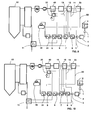
- FIG. 1 An example of a typical water steam cycle of a high efficiency oxy-combustion steam plants is shown in Fig. 1 .
- the plant comprises a triple-pressure series of reheat steam turbines (HP, IP. LP) fed by steam from a boiler (42). Exhaust steam from the last low pressure steam turbine (LP) is condensed in a condenser (2) before being polished (4) and pumped (3) successively through a series of low pressure heater (6, 7, 8, 9, 31), a feed water tank (36) and high pressure heaters (32) before returning to the boiler (42) in a closed loop.
- the heat source for the low and high pressure heaters is typically steam extracted from the low/ intermediate and high pressure steam turbines.
- a coal fired Oxy boiler with oxygen supply system and flue gas CO2 capture system and a steam cycle power plant scheme is provided that integrates major heat generation sources of the systems in order to provide flexible plant operation and improved overall plant thermal efficiency.
- An aspect provides a coal fired Oxy boiler power plant having a combustion system, a CO2 capture system and a steam power plant.
- the combustion system comprises an Air Separation Unit, for removing N2 from air to produce an oxygen stream, having an Air Separation Unit heat exchanger as part of the a compressed air stream used for oxygen stream production, while the steam boiler is adapted to burn coal using the oxygen stream to produce a CO2 rich flue gas stream.
- the CO2 capture system is configured and arranged to remove CO2 from the flue gas stream.
- the steam power plant has a condensate system comprising a condenser for condensing steam, a plurality of low pressure heaters arranged in series and configured and arranged to receive the condensate from the condenser.
- a feed water tank is configured and arranged to receive condensate from the serial low pressure heaters.
- the Air Separation Unit heat exchanger is thermally and fluidly connected to the condensate system so as to be fluidly parallel to at least one serial low pressure heater and fluidly parallel to at least one less that the total number of serial low pressure heaters.
- This arrangement provides the basis for thermal integration of heat sources from to the CO2 capture system, including an Air Separation Unit, a Flue Gas Heat Recovery, a Flue Gas Condenser and/ or a Gas Processing Unit so as to operate the plant at part load down to 40% on oxy mode, in air mode up to 75% load, and in back-up mode with interruption of one of several of heat recovery systems.
- Exemplary embodiments shown in Fig's. 2 to 13 are applied to an oxy-combustion plant having an oxy fired boiler 42 with an integrated CO2 capture system for polishing flue gas emitted from the boiler and separating CO2 therefrom in a Gas Processing Unit and steam/ water Rankine cycle configured to generate electrical power.
- the steam/water cycle includes a condenser extraction pump arrangement having a first stage 1 connected to a condenser 2 outlet and a second stage 3 located at the outlet of a Condensate Polishing Plant 4. This arrangement is located upstream of a condensate heating train consisting of serially arranged low pressure heaters 6, 7, 8, 9, 31. Heated condensate from low pressure heaters 6, 7, 8, 9, 31 is feed into a Feed water tank 36.
- the oxy-combustion plant further includes an Air Separation Unit for removing nitrogen from air to produce an oxygen rich stream to be fed to the boiler 42.
- Thermal energy from the Air Separation Unit is advantageously removed in an Air Separation Unit heat exchanger 11 by heating condensate extracted from the condensate system so as to bypass at less one of the low pressure heaters 6, 7, 8, 9, 31 such that the Air Separation Unit heat exchanger 11 is fluidly parallel to at least one less that the total number of low pressure heaters.
- the oxy combustion plant comprises at least five serial low pressure heaters 6, 7, 8, 9, 31 arranged in a condensate flow series and the Air Separation Unit is fluidly connected to the condensate system at a point upstream of the first of the serial low pressure heaters 6 as well as at a point between the third of the serial low pressure heaters 8 and the fourth of the serial low pressure heaters 9. In this way, condensate passing through the Air Separation Unit heat exchanger 11 bypasses three of the serial low pressure heaters 6, 7, 8.
- the oxy combustion plant comprises at least five serial low pressure heaters 6, 7, 8, 9, 31 arranged in a condensate flow series and the Air Separation Unit is fluidly connected to the condensate system at a point upstream of the first of the serial low pressure heaters 6 as well as at a point between the fourth of the serial low pressure heaters 9 and the fifth of the serial low pressure heaters 31.
- condensate passing through the Air Separation Unit heat exchanger 11 bypasses four of the serial low pressure heaters 6, 7,8,9.
- the oxy combustion plant comprises at least five serial low pressure heaters 6, 7, 8, 9, 31 arranged in a condensate flow series and the Air Separation Unit is fluidly connected to the condensate system at a point between the first of the serial low pressure heaters 6 and the second of the serial low pressure heaters 7 as well as at a point between the third of the serial low pressure heaters 8 and the fourth of the serial low pressure heaters 9.
- condensate passing through the Air Separation Unit heat exchanger 11 bypasses two of the serial low pressure heaters 6, 7.
- the oxy combustion plant comprises at least five low pressure heaters arranged in a condensate flow series and the Air Separation Unit is fluidly connected to the condensate system at a point between the first of the serial low pressure heaters and the second of the serial low pressure heaters as well as at a point between the fourth of the serial low pressure heaters 9 and the fifth of the serial low pressure heaters 31.
- condensate passing through the Air Separation Unit heat exchanger bypasses three of the serial low pressure heaters 7, 8, 9, preferably the second, third and fourth of the serial low pressure heaters 7, 8, 9.
- the oxy combustion plant comprises only 4 serial low pressure heaters 6, 7, 8, 9 instead of at least 5.
- the choice between having either 4 or at least 5 serial low pressure heaters 6, 7, 8, 9, 31 depends on the application of the Flue Gas Condenser and the decision to privilege the capture operation or not,
- Each of the alternate exemplary embodiments makes it possible to match temperatures of the Air Separation Unit to the condensate system thus ensuring optimum heat recovery defined by a combination of outlet temperature and recovery duty criteria thus leading to maximum net energy transfer.
- the coal fired Oxy boiler power plant comprises a plurality of low pressure heaters 6, 7, 8, 9, 31 arranged in a condensate flow series while the CO2 capture system comprises a Flue Gas Condenser 16, for removing condensables from the flue gas stream.
- the Flue Gas Condenser 16 further includes a Flue Gas Condenser condensate line 14 connected to the condensate system at a first end upstream of the first of the serial low pressure heaters 6 and at a second end between the first of the serial low pressure heaters 6 and second of the serial low pressure heaters 7.
- the condensate system further includes a bypass valve 15 between the first of the serial low pressure heaters 6 and the first end of the Flue Gas Condenser condensate line 14 so that, when the bypass valve 15 is closed, condensate fully bypasses the first of the serial low pressure heater 6.
- the condensate system does not include any serial low pressure heaters between the first end and the second end of the Flue Gas Condenser condensate line 14.
- the first of the serial low pressure heaters 6 is located downstream of the second end of the Flue Gas Condenser condensate line 14 and the total number of the serial low pressure heaters is typically four.
- the flow rate of condensate through the Flue Gas Condenser condensate line 14 is controllable by the bypass valve 15 located in the condensate system between the first and second ends of the Flue Gas Condenser condensate line 14.
- the coal fired oxy boiler plant in addition to a condensate system having at least four serial low pressure heaters 6, 7, 8, 9, 31, includes a CO2 capture system with a Flue Gas Heat Recovery System 40 for recovering heat from the flue gas.
- the Flue Gas Heat Recovery System further includes a primary heat recovery loop 39 adapted to flow, in a closed loop, a heat transfer medium through the Flue Gas Heat Recovery System so that the transfer medium exchanges thermal energy with flue gas.
- a control valve 38 is located in the condensate system fluidly between the third of the serial low pressure heaters 8 and the fourth of the serial low pressure heaters 9 at a point upstream of the second end of the Flue Gas Heat Recovery System heat exchanger condensate line 19 and the second end of the Air Separation Unit heat exchanger condensate line 5. This makes it possible to control the ratio of condensate flow between through the Flue Gas Heat Recovery System heat exchanger 22, the Air Separation Unit heat exchanger 11, and upstream serial low pressure heaters 6, 7, 8.
- the coal fired oxy boiler plant in addition to a condensate system having at least four serial low pressure heaters 6, 7, 8, 9, 31 includes a CO2 capture system with a Flue Gas Heat Recovery System 40 for recovering heat from the flue gas.
- the Flue Gas Heat Recovery System further includes a primary heat recovery loop 39 adapted to flow, in a closed loop, a heat transfer medium through the Flue Gas Heat Recovery System so that the transfer medium exchanges thermal energy with flue gas.
- a control valve 38 is located in the condensate system fluidly between the third of the serial low pressure heaters 8 and the fourth of the serial low pressure heaters 9 at a point upstream of the second end of the Air Separation Unit heat exchanger condensate line 5. This makes it possible to control the ratio of condensate flow between through the Flue Gas Heat Recovery System heat exchanger 22, the Air Separation Unit heat exchanger 11, and upstream serial low pressure heaters 6, 7, 8.
- the plant includes a first fluid line 23 and a second fluid line 25.
- the first fluid line 23 has a first end connected to the condensate system between the first of the serial low pressure heaters 6 and a condensate extraction pump second stage 3 located downstream of the condenser 2 and a second end connected to the Flue Gas Heat Recovery System condensate line 19 upstream of the Flue Gas Heat Recovery System heat exchanger 22.
- the first fluid line 23 has a first end connected to the condensate system between the first end of the Flue Gas Condenser condensate line14 and a condensate extraction pump second stage 3 located downstream of the condenser 2 and a second end connected to the Flue Gas Heat Recovery System condensate line 19 upstream of the Flue Gas Heat Recovery System heat exchanger 22.
- the first fluid line 23 includes a valve 24 that is closed during normal operation and open in emergency operation for thermal protection of the Flue Gas Heat Recovery System.
- the Flue Gas Heat Recovery System condensate line 19 When emergency protection is activated, to prevent backflow of condensate through the Flue Gas Heat Recovery System condensate line 19 into the Flue Gas Condenser condensate line 14, the Flue Gas Heat Recovery System condensate line 19 includes a reverse flow prevention means, such as a mechanical or actuated non-return valve, in the Flue Gas Heat Recovery System condensate line 19, fluidly upstream of the first fluid line 23 second end.
- the second fluid line 25 connects the Flue Gas Heat Recovery System heat exchanger with the condenser 2 and includes a valve 26 that is closed during normal operation and open in emergency operation for thermal protection of the Flue Gas Heat Recovery System.
- a valve 29 is located in the Flue Gas Heat Recovery System condensate line 19 fluidly between the second end of the Flue Gas Heat Recovery System condensate line 19 and the second fluid line 25. When closed for emergency protection this enables the flow of condensate from the Flue Gas Heat Recovery System condensate line 19 to the condenser 2.
- the coal fired Oxy boiler power plant comprises five low pressure heaters 6, 7, 8, 9, 31 arranged in a condensate flow series.
- the CO2 capture system comprises a Flue Gas Condenser 16 downstream of the Flue Gas Heat Recovery System 40 and a Gas Processing Unit heat exchanger 33 for cooling of compressed rich-CO2 flue-gas before separation of CO2.
- the Flue Gas Condenser 16 includes a Flue Gas Condenser condensate line 14 connected to the condensate system at a first end upstream of the first of the serial low pressure heaters 6 and at a second end connected to a point between the first of the serial low pressure heaters 6 and the second of the serial low pressure heaters 7.
- the Gas Processing Unit heat exchanger 33 has a Gas Processing Unit condensate line 30 connected at a first end to the condensate system at a point between the first of the serial low pressure heaters 6 and the second of the serial low pressure heaters 7 and connected at a second end to the condensate system at a point fluidly between the fifth of the serial low pressure heaters 31 and the Feed Water Tank 36.
- the coal fired Oxy boiler power plant comprises at least four low pressure heaters 6, 7, 8, 9, 31 arranged in a condensate flow series.
- the CO2 capture system comprises a Flue Gas Condenser 16 downstream of the Flue Gas Heat Recovery System 40 and a Gas Processing Unit heat exchanger 33 for cooling of compressed rich-CO2 flue-gas before separation of CO2.
- the Flue Gas Condenser 16 includes a Flue Gas Condenser condensate line 14 connected to the condensate system, at a first end, upstream of the first of the serial low pressure heaters 6 and, at a second end, to a point between the first of the serial low pressure heaters 6 and the second of the serial low pressure heaters 7.
- the Gas Processing Unit heat exchanger 33 has a Gas Processing Unit condensate line 30 connected, at first end, to the condensate system at a point between the first of the serial low pressure heaters 6 and the second of the serial low pressure heaters 7 and connected, at a second end, to the condensate system at a point between the fourth of the serial low pressure heaters 9 and the fifth of the serial low pressure heaters 31.
- the coal fired oxy boiler power plant has four low pressure heaters 6,7,8,9 while the CO2 capture system further comprises a Flue Gas Condenser 16 having a Flue Gas Condenser condensate line 14 connected at first and second ends upstream of the of the first of the serial low pressure heaters 6.
- a bypass valve 15, for controlling the quantity of condensate flowing through the Flue Gas Condenser is located between the ends of the Flue Gas Condenser condensate line 14.
- the Gas Processing Unit condensate line 30 may be connected to the condensate system at different points. For example, in an exemplary embodiment shown in Fig.
- first and second end of the Gas Processing Unit condensate line 30 are connected to a point between a first of the serial low pressure heaters 6 and a second of the serial low pressure heaters 7 and a point between a fourth of the serial low pressure heaters 9 and a fifth of the serial low pressure heaters 31 respectively.
- first and second ends of the Gas Processing Unit condensate line 30 are connected to a point between a first of the serial low pressure heaters 6 and a second of the serial low pressure heaters 7 and a point between a third of the serial low pressure heaters 8 and a fourth of the serial low pressure heaters 9.
- first and second ends of the Gas Processing Unit condensate line 30 are connected to a point upstream of a first of the serial low pressure heaters 6 and at a point between a fourth of the serial low pressure heaters 9 and the Feed Water Tank 36.
- first and second ends of the Gas Processing Unit condensate line 30 are connected to a point upstream of a first of the serial low pressure heaters 6 and at a point between a third of the serial low pressure heaters 8 and a fourth of the serial low pressure heaters 9.
- first and second ends of the Gas Processing Unit condensate line 30 are connected to a point upstream of a first of the serial low pressure heaters 6 and at a point between a second of the serial low pressure heaters 7 and a third of the serial low pressure heaters 8.
- a control valve 38 is located in the condensate system fluidly between the serial low pressure heaters 6, 7, 8, 9, 31 immediately upstream of the second ends of the condensate lines 5, 19, 30 of the Air Separation Unit heat exchanger 11, the Flue Gas Heater Recovery System heat exchanger 22 and the Gas Processing Unit heat exchanger 33.
Landscapes
- Engineering & Computer Science (AREA)
- Mechanical Engineering (AREA)
- General Engineering & Computer Science (AREA)
- Chemical & Material Sciences (AREA)
- Combustion & Propulsion (AREA)
- Physics & Mathematics (AREA)
- Thermal Sciences (AREA)
- Air Supply (AREA)
- Chimneys And Flues (AREA)
- Treating Waste Gases (AREA)
Priority Applications (10)
| Application Number | Priority Date | Filing Date | Title |
|---|---|---|---|
| PL14290138T PL2942494T3 (pl) | 2014-05-08 | 2014-05-08 | Instalacja opalana mieszanką tlenowo-węglową z integracją ciepła |
| EP14290138.8A EP2942494B1 (fr) | 2014-05-08 | 2014-05-08 | Installation oxy au charbon avec intégration de chaleur |
| AU2015202029A AU2015202029B2 (en) | 2014-05-08 | 2015-04-21 | Coal fired oxy plant with heat integration |
| CA2889174A CA2889174C (fr) | 2014-05-08 | 2015-04-23 | Centrale a oxycombustion alimentee au charbon et a integration de chaleur |
| KR1020150063997A KR101920110B1 (ko) | 2014-05-08 | 2015-05-07 | 열 집적하는 석탄 연소 순산소 발전소 |
| RU2015117507A RU2688078C2 (ru) | 2014-05-08 | 2015-05-07 | Работающая на угле электростанция с оксисжиганием с интеграцией тепла |
| JP2015095708A JP6577745B2 (ja) | 2014-05-08 | 2015-05-08 | 熱統合を用いた石炭燃焼酸素プラント |
| TW104114784A TWI648506B (zh) | 2014-05-08 | 2015-05-08 | 具有熱整合的燃煤氧工廠 |
| CN201510231436.6A CN105091016B (zh) | 2014-05-08 | 2015-05-08 | 带有热联合的燃煤氧气设备 |
| US14/707,744 US10006634B2 (en) | 2014-05-08 | 2015-05-08 | Coal fired oxy plant with air separation unit including parallel coupled heat exchanger |
Applications Claiming Priority (1)
| Application Number | Priority Date | Filing Date | Title |
|---|---|---|---|
| EP14290138.8A EP2942494B1 (fr) | 2014-05-08 | 2014-05-08 | Installation oxy au charbon avec intégration de chaleur |
Publications (2)
| Publication Number | Publication Date |
|---|---|
| EP2942494A1 true EP2942494A1 (fr) | 2015-11-11 |
| EP2942494B1 EP2942494B1 (fr) | 2019-08-21 |
Family
ID=50928036
Family Applications (1)
| Application Number | Title | Priority Date | Filing Date |
|---|---|---|---|
| EP14290138.8A Active EP2942494B1 (fr) | 2014-05-08 | 2014-05-08 | Installation oxy au charbon avec intégration de chaleur |
Country Status (10)
| Country | Link |
|---|---|
| US (1) | US10006634B2 (fr) |
| EP (1) | EP2942494B1 (fr) |
| JP (1) | JP6577745B2 (fr) |
| KR (1) | KR101920110B1 (fr) |
| CN (1) | CN105091016B (fr) |
| AU (1) | AU2015202029B2 (fr) |
| CA (1) | CA2889174C (fr) |
| PL (1) | PL2942494T3 (fr) |
| RU (1) | RU2688078C2 (fr) |
| TW (1) | TWI648506B (fr) |
Cited By (2)
| Publication number | Priority date | Publication date | Assignee | Title |
|---|---|---|---|---|
| CN107551751A (zh) * | 2017-08-30 | 2018-01-09 | 江苏汇创流体工程装备科技有限公司 | 一种燃煤电厂排放烟气中水分及热量回收利用方法及其系统 |
| CN113701142A (zh) * | 2021-08-24 | 2021-11-26 | 浙江天地环保科技股份有限公司 | 一种管式换热器热媒水余热加热凝结水系统及控制方式 |
Families Citing this family (10)
| Publication number | Priority date | Publication date | Assignee | Title |
|---|---|---|---|---|
| EP2942497B1 (fr) | 2014-05-08 | 2018-10-31 | General Electric Technology GmbH | Intégration de chaleur pour système d'alimentation d'installation de chaudière oxy |
| EP2942495B1 (fr) * | 2014-05-08 | 2018-10-10 | General Electric Technology GmbH | Installation oxy au charbon avec intégration de chaleur |
| CN105371291A (zh) * | 2015-11-09 | 2016-03-02 | 华电电力科学研究院 | 烟气余热梯级利用协同脱除so3提高除尘效率的系统 |
| CN109442376A (zh) * | 2018-12-11 | 2019-03-08 | 中国华能集团清洁能源技术研究院有限公司 | 一种空气加热器和低压省煤器联合利用排烟余热系统 |
| CN109520001A (zh) * | 2018-12-12 | 2019-03-26 | 沧州华润热电有限公司 | 一种热网疏水系统 |
| CN110553246A (zh) * | 2019-09-30 | 2019-12-10 | 大唐郓城发电有限公司 | 锅炉烟气余热利用系统及其利用方法 |
| CN110882611B (zh) * | 2019-12-18 | 2024-05-24 | 安徽工业大学 | 一种锅炉烟气脱白系统 |
| CN111396854A (zh) * | 2020-03-26 | 2020-07-10 | 湖州纳尼亚实业有限公司 | 一种水循环热能智能回收系统 |
| CN113251431B (zh) * | 2021-06-17 | 2025-04-01 | 玉锋实业集团有限公司 | 一种烟气消白回收利用淀粉乳升温系统 |
| CN114887409B (zh) * | 2022-04-26 | 2024-07-05 | 成都易态科技有限公司 | 一种将高温烟气余热利用、除尘及脱硝高效结合的方法 |
Citations (6)
| Publication number | Priority date | Publication date | Assignee | Title |
|---|---|---|---|---|
| DE102004059358A1 (de) * | 2003-12-01 | 2005-06-23 | Technische Universität Dresden | Verfahren zur Auskoppelung der Wärme zur Erzielung eines hohen Kraftwerkswirkungsgrades |
| US20060254251A1 (en) * | 2003-07-04 | 2006-11-16 | Katsushige Yamada | Reheat/regenerative type thermal power plant using rankine cycle |
| DE102005026534A1 (de) * | 2005-06-08 | 2006-12-28 | Man Turbo Ag | Dampferzeugungsanlage |
| WO2009010931A2 (fr) * | 2007-07-19 | 2009-01-22 | L'air Liquide-Societe Anonyme Pour L'etude Et L'exploitation Des Procedes Georges Claude | Intégration thermique de centrales d'oxygène |
| DE102009014185A1 (de) * | 2009-03-20 | 2010-09-30 | GMK-Gesellschaft für Motoren und Kraftanlagen mbH | Vorrichtung zur Energieumwandlung nach dem ORC-Prinzip, ORC-Anlage mit einer derartigen Vorrichtung und Verfahren zur Inbetriebnahme und/oder zum Betreiben einer derartigen Vorrichtung |
| EP2706294A1 (fr) * | 2012-09-06 | 2014-03-12 | Alstom Technology Ltd | Chaudière de production d'énergie à oxy-combustion pressurisée et centrale et son procédé de fonctionnement |
Family Cites Families (51)
| Publication number | Priority date | Publication date | Assignee | Title |
|---|---|---|---|---|
| US2921441A (en) | 1953-12-17 | 1960-01-19 | Sulzer Ag | Feed water preheating system for steam power plants |
| US2991620A (en) | 1956-06-11 | 1961-07-11 | Nekolny Jaroslav | Desuperheater arrangements for steam turbines |
| US3032999A (en) | 1959-02-13 | 1962-05-08 | Babcock & Wilcox Ltd | Steam turbine power plants |
| CH401096A (de) | 1963-03-01 | 1965-10-31 | Sulzer Ag | Verfahren und Vorrichtung zur Speisung einer Hilfsturbine in einer Dampfkraftanlage |
| FR89216E (fr) | 1965-01-26 | 1967-05-26 | Babcock & Wilcox France | Association turbine à gaz-turbine à vapeur |
| DE1551264A1 (de) | 1965-03-01 | 1969-06-26 | Steinmueller Gmbh L & C | Kreisprozess fuer Dampfkraftanlagen |
| US3835650A (en) | 1973-05-03 | 1974-09-17 | Gen Electric | Steam air preheater for a steam boiler system |
| US4069674A (en) * | 1977-01-14 | 1978-01-24 | Warren Glenn B | Power plant |
| JPS6088806A (ja) | 1983-10-21 | 1985-05-18 | Mitsui Eng & Shipbuild Co Ltd | 内燃機関の廃熱回収装置 |
| DE3408937A1 (de) | 1984-01-31 | 1985-08-08 | BBC Aktiengesellschaft Brown, Boveri & Cie., Baden, Aargau | Kombinierte gas-/dampf-kraftwerkanlage |
| FI77512C (fi) | 1987-06-18 | 1989-03-10 | Timo Korpela | Foerfarande foer att foerbaettra verkningsgraden i en aongkraftanlaeggningsprocess. |
| US4897999A (en) | 1989-02-03 | 1990-02-06 | Varney John W | Steam power plant |
| JP2792777B2 (ja) | 1992-01-17 | 1998-09-03 | 関西電力株式会社 | 燃焼排ガス中の炭酸ガスの除去方法 |
| JPH062806A (ja) * | 1992-06-22 | 1994-01-11 | Toshiba Corp | 給水加熱装置 |
| US5765365A (en) * | 1993-03-15 | 1998-06-16 | Mitsubishi Jukogyo Kabushiki Kaisha | Coal gasification power generator |
| JP3524939B2 (ja) * | 1993-04-30 | 2004-05-10 | 株式会社東芝 | 排気再燃式複合発電プラント |
| US5345756A (en) | 1993-10-20 | 1994-09-13 | Texaco Inc. | Partial oxidation process with production of power |
| JPH09170405A (ja) * | 1995-12-18 | 1997-06-30 | Ishikawajima Harima Heavy Ind Co Ltd | 加圧流動層複合発電設備 |
| JPH09209715A (ja) * | 1996-02-02 | 1997-08-12 | Hitachi Ltd | 排気再燃型コンバインドプラントの低温腐食防止装置 |
| US5836162A (en) | 1996-08-08 | 1998-11-17 | Power Software Associates, Inc. | Feedwater heater drain recycle system |
| RU2248453C2 (ru) * | 1998-08-31 | 2005-03-20 | III Вильям Скотт Роллинс | Электростанция и способ получения энергии с комбинированием циклов |
| RU2152526C1 (ru) * | 1999-01-25 | 2000-07-10 | Открытое акционерное общество "Энергетический научно-исследовательский институт им. Г.М. Кржижановского" | Способ и энергетическая установка для получения электроэнергии из сланца |
| WO2001090548A1 (fr) | 2000-05-12 | 2001-11-29 | Clean Energy Systems, Inc. | Systemes de generation d'energie par turbine a gaz a cycle de brayton semi-ferme |
| WO2004042200A1 (fr) | 2002-11-08 | 2004-05-21 | Alstom Technology Ltd | Centrale electrique a turbines a gaz et procede pour l'exploiter |
| ZA200304880B (en) * | 2003-02-24 | 2004-05-04 | Air Liquide | Integrated heat recovery systems and methods for increasing the efficiency of an oxygen-fired furnace. |
| EP1643100B1 (fr) | 2004-09-29 | 2017-06-28 | Ansaldo Energia IP UK Limited | Centrale et méthode associée d'opération |
| JP4959156B2 (ja) | 2004-11-29 | 2012-06-20 | 三菱重工業株式会社 | 熱回収設備 |
| JP2007147161A (ja) * | 2005-11-28 | 2007-06-14 | Electric Power Dev Co Ltd | 燃焼装置の排ガス処分方法及び装置 |
| JP2008145007A (ja) * | 2006-12-07 | 2008-06-26 | Ihi Corp | 石炭焚きボイラ装置 |
| US7874140B2 (en) | 2007-06-08 | 2011-01-25 | Foster Wheeler North America Corp. | Method of and power plant for generating power by oxyfuel combustion |
| AU2009338577B2 (en) | 2009-01-28 | 2014-01-30 | Siemens Energy Global GmbH & Co. KG | Method and device for separating carbon dioxide from an exhaust gas of a fossil fired power plant |
| JP5148546B2 (ja) | 2009-04-09 | 2013-02-20 | 三菱重工業株式会社 | 熱回収装置 |
| DE102009056707A1 (de) | 2009-04-18 | 2010-10-21 | Alstom Technology Ltd. | Dampfkraftwerk mit Solarkollektoren |
| WO2010129856A1 (fr) * | 2009-05-08 | 2010-11-11 | Alstom Technology Ltd | Récupération de chaleur à partir d'un procédé de capture de dioxyde de carbone, et procédé de compression pour traitement de combustible |
| DE102009032537A1 (de) | 2009-07-10 | 2011-01-13 | Hitachi Power Europe Gmbh | Kohlekraftwerk mit zugeordneter CO2-Wäsche und Wärmerückgewinnung |
| US20120174622A1 (en) | 2009-07-13 | 2012-07-12 | Alstom Technology Ltd | System for gas processing |
| EP2290200A1 (fr) | 2009-07-15 | 2011-03-02 | Siemens Aktiengesellschaft | Installation de centrale à vapeur dotée d'une unité de turbine à vapeur et récepteur de vapeur de traitement ainsi que procédé de fonctionnement d'une installation de centrale à vapeur dotée d'une unité de turbine à vapeur et récepteur de vapeur de traitement |
| CN102192639A (zh) | 2010-03-09 | 2011-09-21 | 天华化工机械及自动化研究设计院 | 一种增设流化床干燥降低燃煤电厂煤耗的方法 |
| JP5260585B2 (ja) * | 2010-03-12 | 2013-08-14 | 株式会社日立製作所 | 石炭火力発電プラント及び石炭火力発電プラントの運転方法 |
| US20110290163A1 (en) | 2010-05-26 | 2011-12-01 | Hisashi Kobayashi | Hybrid oxy-fuel boiler system |
| US20120129112A1 (en) | 2010-11-22 | 2012-05-24 | Foster Wheeler North America Corp. | Method Of And A System For Combusting Fuel In An Oxyfuel Combustion Boiler |
| JP2014515074A (ja) * | 2011-03-31 | 2014-06-26 | アルストム テクノロジー リミテッド | Co2捕捉のための廃熱を制御するためのシステム及び方法 |
| US8833081B2 (en) * | 2011-06-29 | 2014-09-16 | Alstom Technology Ltd | Low pressure steam pre-heaters for gas purification systems and processes of use |
| JP5450540B2 (ja) | 2011-09-12 | 2014-03-26 | 株式会社日立製作所 | Co2回収装置を備えたボイラーの熱回収システム |
| US20130099508A1 (en) | 2011-10-19 | 2013-04-25 | Alstom Technology Ltd. | Methods for using a carbon dioxide capture system as an operating reserve |
| DE102012013414A1 (de) | 2012-07-05 | 2014-05-08 | Linde Aktiengesellschaft | Verfahren und Vorrichtung zur Umwandlung von Energie |
| US20140060459A1 (en) * | 2012-09-06 | 2014-03-06 | Mitsubishi Heavy Industries, Ltd. | Heat recovery system and heat recovery method |
| US8545782B1 (en) * | 2012-10-16 | 2013-10-01 | Mitsubishi Heavy Industries, Ltd. | CO2 recovery apparatus and CO2 recovery method |
| US20160033128A1 (en) | 2013-03-21 | 2016-02-04 | Siemens Aktiengesellschaft | Power generation system and method to operate |
| CN103234198B (zh) * | 2013-04-19 | 2015-10-28 | 上海交通大学 | 超细煤粉富氧燃烧工艺及系统 |
| EP2942495B1 (fr) * | 2014-05-08 | 2018-10-10 | General Electric Technology GmbH | Installation oxy au charbon avec intégration de chaleur |
-
2014
- 2014-05-08 EP EP14290138.8A patent/EP2942494B1/fr active Active
- 2014-05-08 PL PL14290138T patent/PL2942494T3/pl unknown
-
2015
- 2015-04-21 AU AU2015202029A patent/AU2015202029B2/en active Active
- 2015-04-23 CA CA2889174A patent/CA2889174C/fr active Active
- 2015-05-07 KR KR1020150063997A patent/KR101920110B1/ko active Active
- 2015-05-07 RU RU2015117507A patent/RU2688078C2/ru active
- 2015-05-08 CN CN201510231436.6A patent/CN105091016B/zh active Active
- 2015-05-08 JP JP2015095708A patent/JP6577745B2/ja active Active
- 2015-05-08 TW TW104114784A patent/TWI648506B/zh active
- 2015-05-08 US US14/707,744 patent/US10006634B2/en active Active
Patent Citations (6)
| Publication number | Priority date | Publication date | Assignee | Title |
|---|---|---|---|---|
| US20060254251A1 (en) * | 2003-07-04 | 2006-11-16 | Katsushige Yamada | Reheat/regenerative type thermal power plant using rankine cycle |
| DE102004059358A1 (de) * | 2003-12-01 | 2005-06-23 | Technische Universität Dresden | Verfahren zur Auskoppelung der Wärme zur Erzielung eines hohen Kraftwerkswirkungsgrades |
| DE102005026534A1 (de) * | 2005-06-08 | 2006-12-28 | Man Turbo Ag | Dampferzeugungsanlage |
| WO2009010931A2 (fr) * | 2007-07-19 | 2009-01-22 | L'air Liquide-Societe Anonyme Pour L'etude Et L'exploitation Des Procedes Georges Claude | Intégration thermique de centrales d'oxygène |
| DE102009014185A1 (de) * | 2009-03-20 | 2010-09-30 | GMK-Gesellschaft für Motoren und Kraftanlagen mbH | Vorrichtung zur Energieumwandlung nach dem ORC-Prinzip, ORC-Anlage mit einer derartigen Vorrichtung und Verfahren zur Inbetriebnahme und/oder zum Betreiben einer derartigen Vorrichtung |
| EP2706294A1 (fr) * | 2012-09-06 | 2014-03-12 | Alstom Technology Ltd | Chaudière de production d'énergie à oxy-combustion pressurisée et centrale et son procédé de fonctionnement |
Cited By (2)
| Publication number | Priority date | Publication date | Assignee | Title |
|---|---|---|---|---|
| CN107551751A (zh) * | 2017-08-30 | 2018-01-09 | 江苏汇创流体工程装备科技有限公司 | 一种燃煤电厂排放烟气中水分及热量回收利用方法及其系统 |
| CN113701142A (zh) * | 2021-08-24 | 2021-11-26 | 浙江天地环保科技股份有限公司 | 一种管式换热器热媒水余热加热凝结水系统及控制方式 |
Also Published As
| Publication number | Publication date |
|---|---|
| US20150323180A1 (en) | 2015-11-12 |
| AU2015202029A1 (en) | 2015-11-26 |
| KR20150128597A (ko) | 2015-11-18 |
| RU2015117507A (ru) | 2016-11-27 |
| PL2942494T3 (pl) | 2020-03-31 |
| CN105091016B (zh) | 2020-04-10 |
| TWI648506B (zh) | 2019-01-21 |
| US10006634B2 (en) | 2018-06-26 |
| CA2889174C (fr) | 2020-04-14 |
| RU2688078C2 (ru) | 2019-05-17 |
| TW201610366A (zh) | 2016-03-16 |
| KR101920110B1 (ko) | 2018-11-19 |
| CA2889174A1 (fr) | 2015-11-08 |
| CN105091016A (zh) | 2015-11-25 |
| EP2942494B1 (fr) | 2019-08-21 |
| RU2015117507A3 (fr) | 2018-10-26 |
| JP6577745B2 (ja) | 2019-09-18 |
| AU2015202029B2 (en) | 2018-08-16 |
| JP2015215156A (ja) | 2015-12-03 |
Similar Documents
| Publication | Publication Date | Title |
|---|---|---|
| US10006634B2 (en) | Coal fired oxy plant with air separation unit including parallel coupled heat exchanger | |
| EP2942495B1 (fr) | Installation oxy au charbon avec intégration de chaleur | |
| JP5260585B2 (ja) | 石炭火力発電プラント及び石炭火力発電プラントの運転方法 | |
| EP2942497A1 (fr) | Intégration de chaleur pour système d'alimentation d'installation de chaudière oxy | |
| KR101878536B1 (ko) | 열 통합형 공기 분리 유닛을 갖는 순산소 보일러 발전소 | |
| EP2559866B1 (fr) | Intégration de la chaleur d'une centrale électrique |
Legal Events
| Date | Code | Title | Description |
|---|---|---|---|
| PUAI | Public reference made under article 153(3) epc to a published international application that has entered the european phase |
Free format text: ORIGINAL CODE: 0009012 |
|
| 17P | Request for examination filed |
Effective date: 20140516 |
|
| AK | Designated contracting states |
Kind code of ref document: A1 Designated state(s): AL AT BE BG CH CY CZ DE DK EE ES FI FR GB GR HR HU IE IS IT LI LT LU LV MC MK MT NL NO PL PT RO RS SE SI SK SM TR |
|
| AX | Request for extension of the european patent |
Extension state: BA ME |
|
| RAP1 | Party data changed (applicant data changed or rights of an application transferred) |
Owner name: GENERAL ELECTRIC TECHNOLOGY GMBH |
|
| STAA | Information on the status of an ep patent application or granted ep patent |
Free format text: STATUS: EXAMINATION IS IN PROGRESS |
|
| 17Q | First examination report despatched |
Effective date: 20180503 |
|
| GRAP | Despatch of communication of intention to grant a patent |
Free format text: ORIGINAL CODE: EPIDOSNIGR1 |
|
| STAA | Information on the status of an ep patent application or granted ep patent |
Free format text: STATUS: GRANT OF PATENT IS INTENDED |
|
| RIC1 | Information provided on ipc code assigned before grant |
Ipc: F22D 1/36 20060101ALI20190215BHEP Ipc: F23J 15/06 20060101ALI20190215BHEP Ipc: F23L 7/00 20060101ALI20190215BHEP Ipc: F23J 15/02 20060101ALI20190215BHEP Ipc: F22D 1/02 20060101ALI20190215BHEP Ipc: F01K 13/00 20060101ALI20190215BHEP Ipc: F01K 9/02 20060101ALI20190215BHEP Ipc: F01K 7/40 20060101AFI20190215BHEP |
|
| INTG | Intention to grant announced |
Effective date: 20190325 |
|
| GRAS | Grant fee paid |
Free format text: ORIGINAL CODE: EPIDOSNIGR3 |
|
| GRAA | (expected) grant |
Free format text: ORIGINAL CODE: 0009210 |
|
| STAA | Information on the status of an ep patent application or granted ep patent |
Free format text: STATUS: THE PATENT HAS BEEN GRANTED |
|
| AK | Designated contracting states |
Kind code of ref document: B1 Designated state(s): AL AT BE BG CH CY CZ DE DK EE ES FI FR GB GR HR HU IE IS IT LI LT LU LV MC MK MT NL NO PL PT RO RS SE SI SK SM TR |
|
| REG | Reference to a national code |
Ref country code: GB Ref legal event code: FG4D |
|
| REG | Reference to a national code |
Ref country code: CH Ref legal event code: EP |
|
| REG | Reference to a national code |
Ref country code: DE Ref legal event code: R096 Ref document number: 602014052077 Country of ref document: DE |
|
| REG | Reference to a national code |
Ref country code: AT Ref legal event code: REF Ref document number: 1169996 Country of ref document: AT Kind code of ref document: T Effective date: 20190915 |
|
| REG | Reference to a national code |
Ref country code: IE Ref legal event code: FG4D |
|
| REG | Reference to a national code |
Ref country code: LT Ref legal event code: MG4D |
|
| REG | Reference to a national code |
Ref country code: NL Ref legal event code: MP Effective date: 20190821 |
|
| PG25 | Lapsed in a contracting state [announced via postgrant information from national office to epo] |
Ref country code: FI Free format text: LAPSE BECAUSE OF FAILURE TO SUBMIT A TRANSLATION OF THE DESCRIPTION OR TO PAY THE FEE WITHIN THE PRESCRIBED TIME-LIMIT Effective date: 20190821 Ref country code: NO Free format text: LAPSE BECAUSE OF FAILURE TO SUBMIT A TRANSLATION OF THE DESCRIPTION OR TO PAY THE FEE WITHIN THE PRESCRIBED TIME-LIMIT Effective date: 20191121 Ref country code: NL Free format text: LAPSE BECAUSE OF FAILURE TO SUBMIT A TRANSLATION OF THE DESCRIPTION OR TO PAY THE FEE WITHIN THE PRESCRIBED TIME-LIMIT Effective date: 20190821 Ref country code: SE Free format text: LAPSE BECAUSE OF FAILURE TO SUBMIT A TRANSLATION OF THE DESCRIPTION OR TO PAY THE FEE WITHIN THE PRESCRIBED TIME-LIMIT Effective date: 20190821 Ref country code: BG Free format text: LAPSE BECAUSE OF FAILURE TO SUBMIT A TRANSLATION OF THE DESCRIPTION OR TO PAY THE FEE WITHIN THE PRESCRIBED TIME-LIMIT Effective date: 20191121 Ref country code: HR Free format text: LAPSE BECAUSE OF FAILURE TO SUBMIT A TRANSLATION OF THE DESCRIPTION OR TO PAY THE FEE WITHIN THE PRESCRIBED TIME-LIMIT Effective date: 20190821 Ref country code: PT Free format text: LAPSE BECAUSE OF FAILURE TO SUBMIT A TRANSLATION OF THE DESCRIPTION OR TO PAY THE FEE WITHIN THE PRESCRIBED TIME-LIMIT Effective date: 20191223 Ref country code: LT Free format text: LAPSE BECAUSE OF FAILURE TO SUBMIT A TRANSLATION OF THE DESCRIPTION OR TO PAY THE FEE WITHIN THE PRESCRIBED TIME-LIMIT Effective date: 20190821 |
|
| PG25 | Lapsed in a contracting state [announced via postgrant information from national office to epo] |
Ref country code: AL Free format text: LAPSE BECAUSE OF FAILURE TO SUBMIT A TRANSLATION OF THE DESCRIPTION OR TO PAY THE FEE WITHIN THE PRESCRIBED TIME-LIMIT Effective date: 20190821 Ref country code: LV Free format text: LAPSE BECAUSE OF FAILURE TO SUBMIT A TRANSLATION OF THE DESCRIPTION OR TO PAY THE FEE WITHIN THE PRESCRIBED TIME-LIMIT Effective date: 20190821 Ref country code: GR Free format text: LAPSE BECAUSE OF FAILURE TO SUBMIT A TRANSLATION OF THE DESCRIPTION OR TO PAY THE FEE WITHIN THE PRESCRIBED TIME-LIMIT Effective date: 20191122 Ref country code: IS Free format text: LAPSE BECAUSE OF FAILURE TO SUBMIT A TRANSLATION OF THE DESCRIPTION OR TO PAY THE FEE WITHIN THE PRESCRIBED TIME-LIMIT Effective date: 20191221 Ref country code: RS Free format text: LAPSE BECAUSE OF FAILURE TO SUBMIT A TRANSLATION OF THE DESCRIPTION OR TO PAY THE FEE WITHIN THE PRESCRIBED TIME-LIMIT Effective date: 20190821 Ref country code: ES Free format text: LAPSE BECAUSE OF FAILURE TO SUBMIT A TRANSLATION OF THE DESCRIPTION OR TO PAY THE FEE WITHIN THE PRESCRIBED TIME-LIMIT Effective date: 20190821 |
|
| REG | Reference to a national code |
Ref country code: AT Ref legal event code: MK05 Ref document number: 1169996 Country of ref document: AT Kind code of ref document: T Effective date: 20190821 |
|
| PG25 | Lapsed in a contracting state [announced via postgrant information from national office to epo] |
Ref country code: TR Free format text: LAPSE BECAUSE OF FAILURE TO SUBMIT A TRANSLATION OF THE DESCRIPTION OR TO PAY THE FEE WITHIN THE PRESCRIBED TIME-LIMIT Effective date: 20190821 |
|
| PG25 | Lapsed in a contracting state [announced via postgrant information from national office to epo] |
Ref country code: RO Free format text: LAPSE BECAUSE OF FAILURE TO SUBMIT A TRANSLATION OF THE DESCRIPTION OR TO PAY THE FEE WITHIN THE PRESCRIBED TIME-LIMIT Effective date: 20190821 Ref country code: DK Free format text: LAPSE BECAUSE OF FAILURE TO SUBMIT A TRANSLATION OF THE DESCRIPTION OR TO PAY THE FEE WITHIN THE PRESCRIBED TIME-LIMIT Effective date: 20190821 Ref country code: IT Free format text: LAPSE BECAUSE OF FAILURE TO SUBMIT A TRANSLATION OF THE DESCRIPTION OR TO PAY THE FEE WITHIN THE PRESCRIBED TIME-LIMIT Effective date: 20190821 Ref country code: AT Free format text: LAPSE BECAUSE OF FAILURE TO SUBMIT A TRANSLATION OF THE DESCRIPTION OR TO PAY THE FEE WITHIN THE PRESCRIBED TIME-LIMIT Effective date: 20190821 Ref country code: EE Free format text: LAPSE BECAUSE OF FAILURE TO SUBMIT A TRANSLATION OF THE DESCRIPTION OR TO PAY THE FEE WITHIN THE PRESCRIBED TIME-LIMIT Effective date: 20190821 |
|
| PG25 | Lapsed in a contracting state [announced via postgrant information from national office to epo] |
Ref country code: CZ Free format text: LAPSE BECAUSE OF FAILURE TO SUBMIT A TRANSLATION OF THE DESCRIPTION OR TO PAY THE FEE WITHIN THE PRESCRIBED TIME-LIMIT Effective date: 20190821 Ref country code: SM Free format text: LAPSE BECAUSE OF FAILURE TO SUBMIT A TRANSLATION OF THE DESCRIPTION OR TO PAY THE FEE WITHIN THE PRESCRIBED TIME-LIMIT Effective date: 20190821 Ref country code: IS Free format text: LAPSE BECAUSE OF FAILURE TO SUBMIT A TRANSLATION OF THE DESCRIPTION OR TO PAY THE FEE WITHIN THE PRESCRIBED TIME-LIMIT Effective date: 20200224 Ref country code: SK Free format text: LAPSE BECAUSE OF FAILURE TO SUBMIT A TRANSLATION OF THE DESCRIPTION OR TO PAY THE FEE WITHIN THE PRESCRIBED TIME-LIMIT Effective date: 20190821 |
|
| REG | Reference to a national code |
Ref country code: DE Ref legal event code: R097 Ref document number: 602014052077 Country of ref document: DE |
|
| PLBE | No opposition filed within time limit |
Free format text: ORIGINAL CODE: 0009261 |
|
| STAA | Information on the status of an ep patent application or granted ep patent |
Free format text: STATUS: NO OPPOSITION FILED WITHIN TIME LIMIT |
|
| PG2D | Information on lapse in contracting state deleted |
Ref country code: IS |
|
| 26N | No opposition filed |
Effective date: 20200603 |
|
| PG25 | Lapsed in a contracting state [announced via postgrant information from national office to epo] |
Ref country code: SI Free format text: LAPSE BECAUSE OF FAILURE TO SUBMIT A TRANSLATION OF THE DESCRIPTION OR TO PAY THE FEE WITHIN THE PRESCRIBED TIME-LIMIT Effective date: 20190821 |
|
| REG | Reference to a national code |
Ref country code: DE Ref legal event code: R119 Ref document number: 602014052077 Country of ref document: DE |
|
| PG25 | Lapsed in a contracting state [announced via postgrant information from national office to epo] |
Ref country code: MC Free format text: LAPSE BECAUSE OF FAILURE TO SUBMIT A TRANSLATION OF THE DESCRIPTION OR TO PAY THE FEE WITHIN THE PRESCRIBED TIME-LIMIT Effective date: 20190821 Ref country code: LI Free format text: LAPSE BECAUSE OF NON-PAYMENT OF DUE FEES Effective date: 20200531 Ref country code: CH Free format text: LAPSE BECAUSE OF NON-PAYMENT OF DUE FEES Effective date: 20200531 |
|
| REG | Reference to a national code |
Ref country code: BE Ref legal event code: MM Effective date: 20200531 |
|
| GBPC | Gb: european patent ceased through non-payment of renewal fee |
Effective date: 20200508 |
|
| PG25 | Lapsed in a contracting state [announced via postgrant information from national office to epo] |
Ref country code: LU Free format text: LAPSE BECAUSE OF NON-PAYMENT OF DUE FEES Effective date: 20200508 |
|
| PG25 | Lapsed in a contracting state [announced via postgrant information from national office to epo] |
Ref country code: FR Free format text: LAPSE BECAUSE OF NON-PAYMENT OF DUE FEES Effective date: 20200531 Ref country code: GB Free format text: LAPSE BECAUSE OF NON-PAYMENT OF DUE FEES Effective date: 20200508 Ref country code: IE Free format text: LAPSE BECAUSE OF NON-PAYMENT OF DUE FEES Effective date: 20200508 |
|
| PG25 | Lapsed in a contracting state [announced via postgrant information from national office to epo] |
Ref country code: BE Free format text: LAPSE BECAUSE OF NON-PAYMENT OF DUE FEES Effective date: 20200531 Ref country code: DE Free format text: LAPSE BECAUSE OF NON-PAYMENT OF DUE FEES Effective date: 20201201 |
|
| PG25 | Lapsed in a contracting state [announced via postgrant information from national office to epo] |
Ref country code: MT Free format text: LAPSE BECAUSE OF FAILURE TO SUBMIT A TRANSLATION OF THE DESCRIPTION OR TO PAY THE FEE WITHIN THE PRESCRIBED TIME-LIMIT Effective date: 20190821 Ref country code: CY Free format text: LAPSE BECAUSE OF FAILURE TO SUBMIT A TRANSLATION OF THE DESCRIPTION OR TO PAY THE FEE WITHIN THE PRESCRIBED TIME-LIMIT Effective date: 20190821 |
|
| PG25 | Lapsed in a contracting state [announced via postgrant information from national office to epo] |
Ref country code: MK Free format text: LAPSE BECAUSE OF FAILURE TO SUBMIT A TRANSLATION OF THE DESCRIPTION OR TO PAY THE FEE WITHIN THE PRESCRIBED TIME-LIMIT Effective date: 20190821 |
|
| PGFP | Annual fee paid to national office [announced via postgrant information from national office to epo] |
Ref country code: PL Payment date: 20250423 Year of fee payment: 12 |