EP2946076B1 - Dispositif et procédé d'équilibrage pour une pièce tournante de turbomachine - Google Patents
Dispositif et procédé d'équilibrage pour une pièce tournante de turbomachine Download PDFInfo
- Publication number
- EP2946076B1 EP2946076B1 EP14701807.1A EP14701807A EP2946076B1 EP 2946076 B1 EP2946076 B1 EP 2946076B1 EP 14701807 A EP14701807 A EP 14701807A EP 2946076 B1 EP2946076 B1 EP 2946076B1
- Authority
- EP
- European Patent Office
- Prior art keywords
- balancing
- screws
- type
- screw
- recess
- Prior art date
- Legal status (The legal status is an assumption and is not a legal conclusion. Google has not performed a legal analysis and makes no representation as to the accuracy of the status listed.)
- Active
Links
Images

Classifications
-
- F—MECHANICAL ENGINEERING; LIGHTING; HEATING; WEAPONS; BLASTING
- F01—MACHINES OR ENGINES IN GENERAL; ENGINE PLANTS IN GENERAL; STEAM ENGINES
- F01D—NON-POSITIVE DISPLACEMENT MACHINES OR ENGINES, e.g. STEAM TURBINES
- F01D5/00—Blades; Blade-carrying members; Heating, heat-insulating, cooling or antivibration means on the blades or the members
- F01D5/02—Blade-carrying members, e.g. rotors
- F01D5/027—Arrangements for balancing
-
- F—MECHANICAL ENGINEERING; LIGHTING; HEATING; WEAPONS; BLASTING
- F02—COMBUSTION ENGINES; HOT-GAS OR COMBUSTION-PRODUCT ENGINE PLANTS
- F02C—GAS-TURBINE PLANTS; AIR INTAKES FOR JET-PROPULSION PLANTS; CONTROLLING FUEL SUPPLY IN AIR-BREATHING JET-PROPULSION PLANTS
- F02C7/00—Features, components parts, details or accessories, not provided for in, or of interest apart form groups F02C1/00 - F02C6/00; Air intakes for jet-propulsion plants
- F02C7/04—Air intakes for gas-turbine plants or jet-propulsion plants
-
- F—MECHANICAL ENGINEERING; LIGHTING; HEATING; WEAPONS; BLASTING
- F16—ENGINEERING ELEMENTS AND UNITS; GENERAL MEASURES FOR PRODUCING AND MAINTAINING EFFECTIVE FUNCTIONING OF MACHINES OR INSTALLATIONS; THERMAL INSULATION IN GENERAL
- F16B—DEVICES FOR FASTENING OR SECURING CONSTRUCTIONAL ELEMENTS OR MACHINE PARTS TOGETHER, e.g. NAILS, BOLTS, CIRCLIPS, CLAMPS, CLIPS OR WEDGES; JOINTS OR JOINTING
- F16B23/00—Specially shaped nuts or heads of bolts or screws for rotations by a tool
- F16B23/0007—Specially shaped nuts or heads of bolts or screws for rotations by a tool characterised by the shape of the recess or the protrusion engaging the tool
- F16B23/0038—Specially shaped nuts or heads of bolts or screws for rotations by a tool characterised by the shape of the recess or the protrusion engaging the tool substantially prismatic with up to six edges, e.g. triangular, square, pentagonal, Allen-type cross-sections
-
- F—MECHANICAL ENGINEERING; LIGHTING; HEATING; WEAPONS; BLASTING
- F16—ENGINEERING ELEMENTS AND UNITS; GENERAL MEASURES FOR PRODUCING AND MAINTAINING EFFECTIVE FUNCTIONING OF MACHINES OR INSTALLATIONS; THERMAL INSULATION IN GENERAL
- F16B—DEVICES FOR FASTENING OR SECURING CONSTRUCTIONAL ELEMENTS OR MACHINE PARTS TOGETHER, e.g. NAILS, BOLTS, CIRCLIPS, CLAMPS, CLIPS OR WEDGES; JOINTS OR JOINTING
- F16B23/00—Specially shaped nuts or heads of bolts or screws for rotations by a tool
- F16B23/0053—Specially shaped nuts or heads of bolts or screws for rotations by a tool with a conical or prismatic recess for receiving a centering pin of the tool apparatus
-
- F—MECHANICAL ENGINEERING; LIGHTING; HEATING; WEAPONS; BLASTING
- F16—ENGINEERING ELEMENTS AND UNITS; GENERAL MEASURES FOR PRODUCING AND MAINTAINING EFFECTIVE FUNCTIONING OF MACHINES OR INSTALLATIONS; THERMAL INSULATION IN GENERAL
- F16F—SPRINGS; SHOCK-ABSORBERS; MEANS FOR DAMPING VIBRATION
- F16F15/00—Suppression of vibrations in systems; Means or arrangements for avoiding or reducing out-of-balance forces, e.g. due to motion
- F16F15/32—Correcting- or balancing-weights or equivalent means for balancing rotating bodies, e.g. vehicle wheels
-
- G—PHYSICS
- G01—MEASURING; TESTING
- G01M—TESTING STATIC OR DYNAMIC BALANCE OF MACHINES OR STRUCTURES; TESTING OF STRUCTURES OR APPARATUS, NOT OTHERWISE PROVIDED FOR
- G01M1/00—Testing static or dynamic balance of machines or structures
- G01M1/30—Compensating imbalance
- G01M1/32—Compensating imbalance by adding material to the body to be tested, e.g. by correcting-weights
-
- B—PERFORMING OPERATIONS; TRANSPORTING
- B64—AIRCRAFT; AVIATION; COSMONAUTICS
- B64C—AEROPLANES; HELICOPTERS
- B64C11/00—Propellers, e.g. of ducted type; Features common to propellers and rotors for rotorcraft
- B64C11/008—Propellers, e.g. of ducted type; Features common to propellers and rotors for rotorcraft characterised by vibration absorbing or balancing means
-
- F—MECHANICAL ENGINEERING; LIGHTING; HEATING; WEAPONS; BLASTING
- F01—MACHINES OR ENGINES IN GENERAL; ENGINE PLANTS IN GENERAL; STEAM ENGINES
- F01D—NON-POSITIVE DISPLACEMENT MACHINES OR ENGINES, e.g. STEAM TURBINES
- F01D5/00—Blades; Blade-carrying members; Heating, heat-insulating, cooling or antivibration means on the blades or the members
- F01D5/02—Blade-carrying members, e.g. rotors
- F01D5/025—Fixing blade carrying members on shafts
-
- F—MECHANICAL ENGINEERING; LIGHTING; HEATING; WEAPONS; BLASTING
- F02—COMBUSTION ENGINES; HOT-GAS OR COMBUSTION-PRODUCT ENGINE PLANTS
- F02K—JET-PROPULSION PLANTS
- F02K3/00—Plants including a gas turbine driving a compressor or a ducted fan
- F02K3/02—Plants including a gas turbine driving a compressor or a ducted fan in which part of the working fluid by-passes the turbine and combustion chamber
- F02K3/04—Plants including a gas turbine driving a compressor or a ducted fan in which part of the working fluid by-passes the turbine and combustion chamber the plant including ducted fans, i.e. fans with high volume, low pressure outputs, for augmenting the jet thrust, e.g. of double-flow type
- F02K3/06—Plants including a gas turbine driving a compressor or a ducted fan in which part of the working fluid by-passes the turbine and combustion chamber the plant including ducted fans, i.e. fans with high volume, low pressure outputs, for augmenting the jet thrust, e.g. of double-flow type with front fan
-
- F—MECHANICAL ENGINEERING; LIGHTING; HEATING; WEAPONS; BLASTING
- F05—INDEXING SCHEMES RELATING TO ENGINES OR PUMPS IN VARIOUS SUBCLASSES OF CLASSES F01-F04
- F05D—INDEXING SCHEME FOR ASPECTS RELATING TO NON-POSITIVE-DISPLACEMENT MACHINES OR ENGINES, GAS-TURBINES OR JET-PROPULSION PLANTS
- F05D2220/00—Application
- F05D2220/30—Application in turbines
- F05D2220/36—Application in turbines specially adapted for the fan of turbofan engines
-
- F—MECHANICAL ENGINEERING; LIGHTING; HEATING; WEAPONS; BLASTING
- F05—INDEXING SCHEMES RELATING TO ENGINES OR PUMPS IN VARIOUS SUBCLASSES OF CLASSES F01-F04
- F05D—INDEXING SCHEME FOR ASPECTS RELATING TO NON-POSITIVE-DISPLACEMENT MACHINES OR ENGINES, GAS-TURBINES OR JET-PROPULSION PLANTS
- F05D2250/00—Geometry
- F05D2250/20—Three-dimensional
- F05D2250/23—Three-dimensional prismatic
- F05D2250/232—Three-dimensional prismatic conical
-
- F—MECHANICAL ENGINEERING; LIGHTING; HEATING; WEAPONS; BLASTING
- F05—INDEXING SCHEMES RELATING TO ENGINES OR PUMPS IN VARIOUS SUBCLASSES OF CLASSES F01-F04
- F05D—INDEXING SCHEME FOR ASPECTS RELATING TO NON-POSITIVE-DISPLACEMENT MACHINES OR ENGINES, GAS-TURBINES OR JET-PROPULSION PLANTS
- F05D2260/00—Function
- F05D2260/30—Retaining components in desired mutual position
- F05D2260/31—Retaining bolts or nuts
-
- Y—GENERAL TAGGING OF NEW TECHNOLOGICAL DEVELOPMENTS; GENERAL TAGGING OF CROSS-SECTIONAL TECHNOLOGIES SPANNING OVER SEVERAL SECTIONS OF THE IPC; TECHNICAL SUBJECTS COVERED BY FORMER USPC CROSS-REFERENCE ART COLLECTIONS [XRACs] AND DIGESTS
- Y02—TECHNOLOGIES OR APPLICATIONS FOR MITIGATION OR ADAPTATION AGAINST CLIMATE CHANGE
- Y02T—CLIMATE CHANGE MITIGATION TECHNOLOGIES RELATED TO TRANSPORTATION
- Y02T50/00—Aeronautics or air transport
- Y02T50/60—Efficient propulsion technologies, e.g. for aircraft
-
- Y—GENERAL TAGGING OF NEW TECHNOLOGICAL DEVELOPMENTS; GENERAL TAGGING OF CROSS-SECTIONAL TECHNOLOGIES SPANNING OVER SEVERAL SECTIONS OF THE IPC; TECHNICAL SUBJECTS COVERED BY FORMER USPC CROSS-REFERENCE ART COLLECTIONS [XRACs] AND DIGESTS
- Y10—TECHNICAL SUBJECTS COVERED BY FORMER USPC
- Y10T—TECHNICAL SUBJECTS COVERED BY FORMER US CLASSIFICATION
- Y10T29/00—Metal working
- Y10T29/49—Method of mechanical manufacture
- Y10T29/49316—Impeller making
- Y10T29/4932—Turbomachine making
- Y10T29/49321—Assembling individual fluid flow interacting members, e.g., blades, vanes, buckets, on rotary support member
Definitions
- the present invention relates to a balancing device for a rotating part of a turbomachine, as well as a method for balancing a rotating part of a turbomachine provided with such a balancing device.
- front and rear are to be considered with respect to a general direction of flow of fluids through the turbomachine, ranging from front to back as shown schematically by an arrow 100.
- the turbomachine comprises so-called major modules, themselves comprising so-called minor modules.
- This distribution in modules allows an easy assembly system by sub-elements, but also a distribution of unbalances by modular balancing.
- each rotating minor module is dynamically balanced in order to reduce its unbalance and thus limit the impact on the motor once it is assembled.
- An unbalance is a parasitic mass causing an imbalance of a rotating part.
- the turbomachine itself is balanced.
- the rear ferrule 12 has thirty-six holes 17 distributed over its periphery, in which nuts 18 are crimped.
- the crimped nuts 18 are suitable for receiving so-called balancing screws making it possible to limit the overall unbalance of the turbomachine. Indeed, by judiciously choosing the weights of the balancing screws to be screwed into the nuts 18, the turbomachine is balanced.
- the engine balancing function by implanting balancing screws of different lengths and masses is difficult to achieve.
- the front cone is of small diameter so that the center of gravity of the screws is then very close to the engine axis, which reduces their total balancing capacity.
- the diameter and the reduced environment make it necessary to reduce the number of screws used and to take screws with a small threaded diameter, which leads to a decrease in the total mass of the screws, and therefore in the balancing capacity. total.
- the balancing screws make the turbomachine heavier.
- FR 2920187 A1 discloses a balancing device for a rotating part of a turbomachine according to the prior art.
- US 2385252 discloses a balancing device for a rotating part according to the preamble of claim 1.
- the invention aims to remedy the drawbacks of the state of the art by proposing a balancing screw for a balancing device which allows the balancing device to be used in small engines, which is optimized in terms of mass compared to to that of the prior art.
- a balancing device for a rotating part of a turbomachine according to claim 1.
- the clamping head is pierced by a recess formed by the clamping indentation and by an additional recess which extends the clamping indentation.
- the additional recess preferably has a cylindrical shape so as to facilitate its manufacture.
- the additional recess preferably has dimensions smaller than those of the clamping cavity so that a tightening key inserted in the clamping cavity can come into abutment at the bottom of the clamping cavity. , at the limit with the additional recess.
- the fact of using different materials for the balancing screws allows to have more possibilities to balance the rotating part, which is advantageous in the case where the ferrule is of small dimensions, and where the possibilities of balancing by Changes to the external dimensions of the balancing screws are limited.
- the balancing screws preferably have cylindrical screw heads, which makes it possible to facilitate the manufacture of the balancing screws.
- this makes it possible to further increase the mass of their head.
- the fact of increasing the mass of the heads of the screws of the second kind makes it possible to move their center of gravity towards the head of said screws, and therefore to move it away from the motor axis, which makes it possible to increase the capacity of balancing screws.
- the balancing device may also include screws of the rotating machine. 'intermediate balancing, each intermediate screw having a mass between the mass of one of the screws of the first kind and the mass of one of the screws of the second kind. These intermediate balancing screws make it possible to respect all the balancing criteria and to achieve nuances in the balancing.
- the dimensions of the heads of the screws can be varied so as to balance the rotating part.
- the variation in the mass of each head can therefore be used to compensate for variations in the mass of the screw body.
- the mass of the body of the screws is constrained by the space available inside the ferrule. We can therefore use the screw heads to have more possibilities to balance the rotating machine.
- the figures 2 and 4 to 6 represent an inlet cowl 20 of a turbomachine comprising a balancing device according to one embodiment of the invention.
- This inlet cover 20 comprises a cone 21 provided with a balancing device 22.
- the balancing device 22 comprises a ferrule 23.
- the ferrule 23 has in this case a conical shape.
- the ferrule 23 is formed by a rear part of the cone 21.
- the ferrule 23 is formed by an additional part 24 which has a symmetry of revolution and which is connected to the cone 21.
- the ferrule 23 is pierced by orifices 25 which are distributed radially over the entire periphery of the ferrule 23.
- the ferrule 23 is pierced by twenty orifices 25.
- the number of orifices depends in particular on the diameter. of the shell 23 and the precision required for balancing.
- the balancing device also comprises nuts 26, each nut 26 being crimped in one of the orifices 25.
- the crimped nuts 26 are suitable for receiving so-called balancing screws 27, 27 'so as to reduce or even eliminate the unbalance of the turbomachine.
- balancing screws 27 of a first kind are first inserted into each of the orifices 25 and screwed into each of the nuts.
- the turbomachine is then rotated so as to detect the presence of any unbalance.
- some screws of the first type 27 are then replaced by balancing screws of a second type 27 'so as to reduce the unbalance.
- the balancing screws of the first type 27 and of the second type 27 ' are distributed radially around the shell so as to reduce the unbalance of the turbomachine.
- five screws of the first type 27 have been replaced by five screws of the second type 27 ', however, the radial distribution and the respective number of screws of the first type and of the second type depend on the unbalance.
- the balancing screws in the second type 27 ' have a mass greater than that of the screws of the first type 27.
- a screw of the first kind 27 is shown more precisely on the figure 7 .
- the balancing screw of the first type 27 extends along a reference axis 31.
- the balancing screw of the first type 27 is preferably made of titanium.
- the balancing screw of the first kind 27 has a head 29 and a body 30.
- the body 30 of the balancing screw of the first kind 27 has on its outer surface a thread 35 for screwing in the balancing screw of the first kind. the first kind 27 in the nut 26.
- the body 30 of the screw of the first kind 27 has a length l1 sufficient to be able to be fully screwed into the nut 26. However, the length l1 is preferably chosen so that that the body 30 does not protrude too much from the nut 26 so as not to weigh down the turbomachine too much.
- the head 29 of the screw of the first kind is pierced by a recess 32.
- the recess 32 is formed by a clamping recess 33 and by an additional recess 34 located in the axial extension of the clamping recess 33.
- L ' clamping cavity 33 has a bottom 40 which is pierced by the additional recess 34.
- the clamping cavity 33 is able to receive a tightening key allowing the screw to be screwed into the corresponding nut 26.
- the clamping cavity 33 preferably has a hexagonal section.
- the additional recess 34 preferably has a cylindrical shape so as to facilitate its machining.
- the head 29 is preferably cylindrical to facilitate its manufacture.
- the dimensions of the screws of the first kind 27 can be modified as a function of the mass which they must have in order to balance the turbomachine.
- the depth p1 of the recess 32 is modified. Its shape can also be modified. It is also possible to envisage modifying the shape of the head 29.
- a screw of the second kind 27 ' is shown more precisely on the figure 8 .
- the balancing screws of the second type 27 ' are substituted for some of the balancing screws of the first type 27 so as to reduce the unbalance of the turbomachine.
- the second kind of balancing screw 27 ' is preferably made of steel.
- the second kind of balancing screw 27 ' also extends along a reference axis 31' and it also has a head 29 'and a body 30'.
- the body 30 'of the balancing screw of the second kind 27' also comprises on its outer surface a thread 35 'allowing the balancing screw of the second kind 27' to be screwed into the nut 26.
- the body 30 ' preferably has a length 12 greater than the length 11 of the body 30 of the balancing screw of the first kind 27.
- the head 29 ' is pierced by a recess 32'.
- the recess 32 ′ is formed in this exemplary embodiment by a clamping cavity 33 ′.
- the recess 32 'does not extend beyond the clamping cavity 33'. Consequently, according to the invention, the depth p2 of the recess 32 'corresponds to the depth of the clamping cavity 33'. The depth p2 is therefore less than the depth p1.
- the recess 32 'of the balancing screw of the second kind 27' is therefore minimal in this embodiment so as to maximize the mass of the heads and therefore the balancing capacity of the screw.
- the head is preferably cylindrical so as to maximize its mass.
- the dimensions of the screws of the second kind 27 ' can be modified as a function of the mass which they must have in order to balance the turbomachine.
- this length 12 is limited by the space inside the ferrule. Therefore, it is advantageous to modify the mass of the head 29 'to achieve the desired balance.
- the depth p2 of the recess 32 ' is modified. You can also change its shape. It is also possible to envisage modifying the shape of the head 29 '.
- all the balancing screws of the first kind 27 were identical to each other, as were all the screws. balance of the second kind 27 'being identical to each other.
Landscapes
- Engineering & Computer Science (AREA)
- General Engineering & Computer Science (AREA)
- Mechanical Engineering (AREA)
- Physics & Mathematics (AREA)
- Chemical & Material Sciences (AREA)
- Combustion & Propulsion (AREA)
- Acoustics & Sound (AREA)
- Aviation & Aerospace Engineering (AREA)
- General Physics & Mathematics (AREA)
- Turbine Rotor Nozzle Sealing (AREA)
- Structures Of Non-Positive Displacement Pumps (AREA)
- Testing Of Balance (AREA)
Description
- La présente invention concerne un dispositif d'équilibrage pour une pièce tournante de turbomachine, ainsi qu'un procédé d'équilibrage d'une pièce tournante de turbomachine pourvue d'un tel dispositif d'équilibrage.
- Un capot d'entrée 10 tournant de turbomachine d'aéronef comporte généralement deux parties fixées l'une à l'autre, comme représenté à la
figure 1 : - une partie avant en forme de cône, appelée cône avant 11. Le cône avant 11 présente une extrémité avant 13 en forme de pointe de cône centrée sur un axe de rotation X du capot d'entrée 10, correspondant également à un axe longitudinal de l'ensemble de la turbomachine. Le cône avant 11 présente également une extrémité arrière 14 s'étendant radialement par rapport à l'axe X selon une forme annulaire.
- une partie arrière, appelée virole arrière 12, s'étendant selon l'axe longitudinal X de la turbomachine et prolongeant le cône avant 11. La virole arrière 12 présente une extrémité avant 15 s'étendant radialement par rapport à l'axe X selon une forme annulaire. De façon classique, le cône avant 11 et la virole arrière 12 sont fixés par des boulons 16 traversant d'avant en arrière l'extrémité arrière 14 du cône avant 11 et l'extrémité avant 15 de la virole arrière 12.
- On note que les termes « avant » et « arrière » sont à considérer par rapport à une direction générale d'écoulement de fluides à travers la turbomachine, allant de l'avant vers l'arrière comme cela est représenté schématiquement par une flèche 100.
- De manière connue, la turbomachine comporte des modules dits majeurs, euxmêmes comportant des modules dits mineurs. Cette répartition en modules permet un système d'assemblage aisé par sous-éléments, mais également une répartition des balourds par équilibrage modulaire. En effet, chaque module mineur tournant est équilibré en dynamique afin de réduire son balourd et ainsi limiter les impacts sur le moteur une fois que celui-ci est assemblé. Un balourd est une masse parasite entrainant un déséquilibre d'une pièce tournante.
- Puis, une fois assemblé, la turbomachine est elle-même équilibrée. Classiquement, la virole arrière 12 dispose de trente-six trous 17 répartis sur sa périphérie, dans lesquels sont sertis des écrous 18. Les écrous sertis 18 sont aptes à recevoir des vis dites d'équilibrage permettant de limiter le balourd global de la turbomachine. En effet, en choisissant judicieusement les poids des vis d'équilibrage à visser dans les écrous 18, on équilibre la turbomachine.
- Toutefois, dans les petits moteurs, la fonction d'équilibrage moteur par implantation de vis d'équilibrage de longueurs et de masses différentes est difficile à réaliser. En effet, dans les petits moteurs, le cône avant est de petit diamètre de sorte que le centre de gravité des vis se trouve alors très proche de l'axe moteur ce qui diminue leur capacité d'équilibrage totale. En outre, le diamètre et l'environnement réduit oblige à réduire le nombre de vis utilisées et à prendre des vis avec un petit diamètre fileté, ce qui conduit à une diminution de la masse totale des vis, et donc de la capacité d'équilibrage totale. En outre, dans les petits moteurs, les vis d'équilibrage alourdissent la turbomachine.
-
FR 2920187 A1 -
US 2385252 divulgue un dispositif d'équilibrage pour une pièce tournante selon le préambule de la revendication 1. - L'invention vise à remédier aux inconvénients de l'état de la technique en proposant une vis d'équilibrage pour dispositif d'équilibrage qui permette au dispositif d'équilibrage d'être utilisé dans les petits moteurs, qui soit optimisée en masse par rapport à celle de l'art antérieur.
- Pour ce faire, est proposé selon un premier aspect de l'invention, un dispositif d'équilibrage pour une pièce tournante de turbomachine selon la revendication 1.
- Le fait d'avoir un évidement additionnel qui prolonge axialement l'empreinte de serrage permet d'avoir une vis d'équilibrage plus légère. En effet, on peut ainsi diminuer la masse des vis sans modifier leurs dimensions extérieures, ce qui est avantageux car tous les orifices de la virole destinés à recevoir des vis doivent obligatoirement être obstrués par des vis même si certaines de ces vis ne sont pas utiles pour l'équilibrage, car ces orifices débouchent dans la veine. Par conséquent, il est avantageux d'avoir des vis de masse faible pour ne pas trop alourdir la turbomachine. Dans ce cas, la tête de serrage est percée par un évidement formé par l'empreinte de serrage et par un évidement additionnel qui prolonge l'empreinte de serrage. L'évidement additionnel présente de préférence une forme cylindrique de façon à faciliter sa fabrication. En outre, l'évidement additionnel présente de préférence des dimensions inférieures à celles de l'empreinte de serrage de façon à ce qu'une clé de serrage insérée dans l'empreinte de serrage puisse venir en butée au fond de l'empreinte de serrage, à la limite avec l'évidement additionnel.
- Le fait d'avoir un dispositif d'équilibrage dans lequel on fait varier la profondeur de l'évidement des têtes de vis de façon à compenser le balourd permet d'avoir plus de possibilités pour équilibrer la turbomachine, y compris lorsqu'elle présente des petites dimensions. En effet, le fait de faire varier la profondeur de l'évidement permet une plus grande variation de la masse et de la position du centre de gravité des vis d'équilibrage, ce qui permet d'avoir plus de possibilités pour équilibrer le moteur, y compris lorsque ce moteur présente des dimensions réduites. On peut ainsi faire varier la masse des vis d'équilibrage sans faire varier leurs dimensions extérieures.
- L'évidement des vis d'équilibrage de la deuxième sorte correspond à l'empreinte de serrage des vis d'équilibrage de la deuxième sorte. Ainsi, les vis d'équilibrage de la deuxième sorte présentent de préférence un évidement minimal, qui leur permet d'avoir une masse plus importante. Dans ce cas, l'évidement qui correspond à l'empreinte de serrage présente de préférence une forme adaptée à celle de la clé de serrage qui est destinée à être insérée dans l'empreinte de serrage. Selon un mode de réalisation :
- les vis d'équilibrage de la première sorte sont réalisées dans un matériau présentant une première masse volumique m1,
- les vis d'équilibrage de la deuxième sorte étant réalisées dans un matériau présentant une deuxième masse volumique m2, la deuxième masse volumique m2 étant strictement supérieure à la première masse volumique m1.
- Le fait d'utiliser des matériaux différents pour les vis d'équilibrage permet d'avoir plus de possibilités pour équilibrer la pièce tournante, ce qui est avantageux dans le cas où la virole est de petites dimensions, et où les possibilités d'équilibrage par modifications des dimensions extérieures des vis d'équilibrage sont limitées.
- Avantageusement, les vis d'équilibrage de la première sorte sont réalisées en titane. Avantageusement, les vis d'équilibrage de la deuxième sorte sont réalisées en acier. Selon un mode de réalisation :
- les vis de la première sorte présentent une première longueur l1 ;
- les vis de la deuxième sorte présentent une deuxième longueur l2, la deuxième longueur l2 étant strictement supérieure à la première longueur l1.
- Ce qui permet encore d'augmenter la variation de masse entre les vis de la première sorte et les vis de la deuxième sorte.
- Les vis d'équilibrages présentent de préférence des têtes de vis cylindriques, ce qui permet de faciliter la fabrication des vis d'équilibrage. En outre, dans le cas des vis d'équilibrage de la deuxième sorte, cela permet d'augmenter encore la masse de leur tête. Le fait d'augmenter la masse des têtes des vis de la deuxième sorte permet de déplacer leur centre de gravité vers la tête desdites vis, et donc de l'éloigner de l'axe moteur, ce qui permet d'augmenter la capacité d'équilibrage des vis.
- Selon différents modes de réalisation :
- la tête de chaque vis d'équilibrage de la première sorte peut présenter une masse au moins égale à 60% de la masse totale de ladite vis d'équilibrage ; et/ou
- la tête de chaque vis d'équilibrage de la deuxième sorte peut présenter une masse au moins égale à 40% de la masse totale de ladite vis d'équilibrage.
- Le fait d'avoir une tête relativement lourde par rapport au poids total de la vis permet de déplacer le centre de gravité des vis vers ladite tête, ce qui permet d'augmenter la capacité d'équilibrage des vis.
- De manière plus générale, on peut utiliser des vis d'équilibrage avec des têtes de vis plus ou moins grandes pour compenser la longueur du corps de vis. Ainsi, lorsque l'espace est limité dans la virole et que par conséquent, la taille des corps de vis est limitée, on peut compenser la taille du corps des vis par celle des têtes de vis.
- On peut envisager que toutes les vis d'équilibrage de la première sorte soit identiques entre elles de façon à simplifier la fabrication du dispositif d'équilibrage. Pour les mêmes raisons, on peut également envisager que toutes les vis d'équilibrage de la deuxième sorte soient identiques entre elles de façon à simplifier la fabrication du dispositif.
- Dans ce cas, lorsque l'utilisation de deux groupes de vis d'équilibrage identiques à l'intérieur de chacun des groupes n'est pas suffisante pour compenser le balourd de la machine tournante, le dispositif d'équilibrage peut également comporter des vis d'équilibrage intermédiaires, chaque vis intermédiaire présentant une masse comprise entre la masse d'une des vis de la première sorte et la masse d'une des vis de la deuxième sorte. Ces vis d'équilibrages intermédiaires permettent de respecter tous les critères d'équilibrage et de réaliser des nuances dans l'équilibrage.
- Les vis d'équilibrage intermédiaires peuvent par exemple être :
- des vis réalisées dans le même matériau et qui présentent les mêmes dimensions extérieures que les vis d'équilibrage de la première sorte, mais qui ne comportent pas d'évidement additionnel au-delà de leur empreinte de serrage ;
- des vis qui présentent des dimensions égales à celles des vis de la première sorte mais qui sont réalisées dans un matériau dont la masse volumique est supérieure à celle du matériau des vis de la première sorte ;
- des vis qui sont réalisées dans le même matériau que les vis de la première sorte mais qui présentent des dimensions inférieures...
- On peut notamment faire varier les dimensions des têtes des vis de façon à équilibrer la pièce tournante.
- Un deuxième aspect de l'invention concerne un procédé d'équilibrage d'une pièce tournante de turbomachine pourvue d'un dispositif d'équilibrage selon le premier aspect de l'invention, le procédé comportant une étape d'ajustement de la profondeur de l'évidement des têtes de vis de façon à équilibrer la pièce tournante. Avantageusement, le procédé d'équilibrage comporte en outre une étape d'ajustement d'un ou plusieurs des paramètres suivants pour équilibrer la pièce tournante :
- les dimensions extérieures de chacune des têtes de vis;
- la forme des têtes de vis ;
- le matériau des vis d'équilibrage.
- La variation de la masse de chaque tête peut donc être utilisée qui compenser des variations de la masse du corps de vis. En effet, la masse du corps des vis est contrainte par l'espace disponible à l'intérieur de la virole. On peut donc utiliser les têtes de vis pour avoir plus de possibilités pour équilibrer la machine tournante.
- D'autres caractéristiques et avantages de l'invention ressortiront à la lecture de la description détaillée qui suit, en référence aux figures annexées, qui illustrent :
- La
figure 1 , une vue en coupe d'un capot d'entrée de turbomachine de l'art antérieur ; - La
figure 2 , une vue en perspective d'un capot d'entrée de turbomachine selon un mode de réalisation de l'invention ; - La
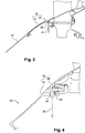
figure 3 , une vue en coupe du capot d'entrée de lafigure 2 ; - La
figure 4 , une vue en coupe agrandie d'une partie du capot d'entrée de lafigure 2 ; - La
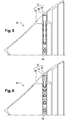
figure 5 , une autre vue en coupe d'une partie du capot d'entrée de lafigure 2 ; - La
figure 6 , une autre vue en coupe d'une autre partie du capot d'entrée de lafigure 2 ; - La
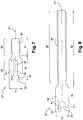
figure 7 , une vue en coupe d'une des vis du capot d'entrée de lafigure 2 ; - La
figure 8 , une vue en coupe d'une autre vis du capot d'entrée de lafigure 2 . - Pour plus de clarté, les éléments identiques ou similaires sont repérés par des signes de références identiques sur l'ensemble des figures.
- Les
figures 2 et4 à 6 représentent un capot d'entrée 20 de turbomachine comportant un dispositif d'équilibrage selon un mode de réalisation de l'invention. - Ce capot d'entrée 20 comporte un cône 21 pourvu d'un dispositif d'équilibrage 22. Le dispositif d'équilibrage 22 comporte une virole 23. La virole 23 présente dans ce cas une forme conique. Dans ce mode de réalisation, la virole 23 est formée par une partie arrière du cône 21. Toutefois, dans le mode de réalisation de la
figure 3 , la virole 23 est formée par une pièce additionnelle 24 qui présente une symétrie de révolution et qui est relié au cône 21. - La virole 23 est percée par des orifices 25 qui sont répartis radialement sur l'ensemble du pourtour de la virole 23. Dans ce mode de réalisation, la virole 23 est percée par vingt orifices 25. Toutefois le nombre d'orifices dépend notamment du diamètre de la virole 23 et de la précision voulue pour l'équilibrage.
- Le dispositif d'équilibrage comporte également des écrous 26, chaque écrou 26 étant serti dans un des orifices 25. Les écrous 26 sertis sont aptes à recevoir des vis dites d'équilibrage 27, 27' de façon à diminuer voir supprimer le balourd de la turbomachine.
- Pour cela, des vis d'équilibrage 27 d'une première sorte sont tout d'abord insérées dans chacun des orifices 25 et vissées dans chacun des écrous.
- La turbomachine est ensuite mise en rotation de façon à détecter la présence d'un éventuel balourd.
- Si un balourd est détecté, certaines vis de la première sorte 27 sont alors remplacées par des vis d'équilibrage d'une deuxième sorte 27' de façon à diminuer le balourd. Les vis d'équilibrage de la première sorte 27 et de la deuxième sorte 27' sont réparties radialement autour de la virole de façon à diminuer le balourd de la turbomachine. Dans cet exemple de réalisation cinq vis de la première sorte 27 ont été remplacées par cinq vis de la deuxième sorte 27', toutefois, la répartition radiale et le nombre respectif des vis de la première sorte et de la deuxième sorte dépendent du balourd.
- Les vis d'équilibrage dans la deuxième sorte 27' présentent une masse supérieure à celle des vis de la première sorte 27.
- Une vis de la première sorte 27 est représentée plus précisément sur la
figure 7 . - La vis d'équilibrage de la première sorte 27 s'étend suivant un axe de référence 31. La vis d'équilibrage de la première sorte 27 est de préférence réalisée en titane. La vis d'équilibrage de la première sorte 27 comporte une tête 29 et un corps 30. Le corps 30 de la vis d'équilibrage de la première sorte 27 comporte sur sa surface extérieure un filetage 35 permettant de visser la vis d'équilibrage de la première sorte 27 dans l'écrou 26. Le corps 30 de la vis de la première sorte 27 présente une longueur l1 suffisante pour pouvoir être entièrement vissé dans l'écrou 26. Toutefois, la longueur l1 est de préférence choisie de façon à ce que le corps 30 ne dépasse pas trop de l'écrou 26 de façon à ne pas trop alourdir la turbomachine. La tête 29 de la vis de la première sorte est percée par un évidement 32. L'évidement 32 est formé par une empreinte de serrage 33 et par un évidement additionnel 34 situé dans le prolongement axial de l'empreinte de serrage 33. L'empreinte de serrage 33 présente un fond 40 qui est percé par l'évidement additionnel 34. L'empreinte de serrage 33 est apte à recevoir une clé de serrage permettant de visser la vis dans l'écrou 26 correspondant. Pour cela, l'empreinte de serrage 33 présente de préférence une section hexagonale. L'évidement additionnel 34 présente de préférence une forme cylindrique de façon à faciliter son usinage. Par ailleurs, il présente de préférence des dimensions transversales par rapport à l'axe de référence 31 inférieures à celles de l'empreinte de serrage 33 de sorte qu'une clé de serrage insérée dans l'empreinte de serrage 33 vienne en butée contre le fond 40, à la limite entre l'empreinte de serrage 33 et l'évidement additionnel 34. La profondeur p1 de l'évidement 32 est ajustée en fonction de la masse voulue pour la vis et plus précisément pour la tête de cette vis. De la même manière, les dimensions transversales de l'évidement additionnel peuvent être ajustées en fonction de la masse voulue pour la vis et plus précisément pour la tête de la vis. La tête 29 est de préférence cylindrique pour faciliter sa fabrication.
- Les dimensions des vis de la première sorte 27 peuvent être modifiées en fonction de la masse qu'elles doivent avoir pour équilibrer la turbomachine. Ainsi, on peut tout d'abord modifier la longueur l1 du corps 30 des vis de la première sorte 27. On peut également modifier la masse de la tête 29 pour obtenir l'équilibrage voulu. Pour cela, on peut notamment modifier les dimensions d1 de la tête 29, et notamment sa hauteur l3. Selon l'invention, on modifie la profondeur p1 de l'évidement 32. On peut également modifier sa forme. On peut également envisager de modifier la forme de la tête 29.
- Une vis de la deuxième sorte 27' est représentée plus précisément sur la
figure 8 . Les vis d'équilibrage de la deuxième sorte 27' sont substituées à certaines des vis d'équilibrage de la première sorte 27 de façon à diminuer le balourd de la turbomachine. - La vis d'équilibrage de la deuxième sorte 27' est de préférence réalisée en acier. La vis d'équilibrage de la deuxième sorte 27' s'étend également suivant un axe de référence 31' et elle présente également une tête 29' et un corps 30'. Le corps 30' de la vis d'équilibrage de la deuxième sorte 27' comporte également sur sa surface extérieure un filetage 35' permettant de visser la vis d'équilibrage de la deuxième sorte 27' dans l'écrou 26. Le corps 30' présente de préférence une longueur l2 supérieure à la longueur l1 du corps 30 de la vis d'équilibrage de la première sorte 27. La tête 29' est percée par un évidement 32'. L'évidement 32' est formé dans cet exemple de réalisation par une empreinte de serrage 33'. Dans ce mode de réalisation, l'évidement 32' ne se prolonge pas au-delà de l'empreinte de serrage 33'. Par conséquent, selon l'invention, la profondeur p2 de l'évidement 32' correspond à la profondeur de l'empreinte de serrage 33'. La profondeur p2 est donc inférieure à la profondeur p1. L'évidement 32' de la vis d'équilibrage de la deuxième sorte 27' est donc minimal dans ce mode de réalisation de façon à maximiser la masse des têtes et donc la capacité d'équilibrage de la vis. De même, la tête est de préférence cylindrique de façon à maximiser sa masse.
- Les dimensions des vis de la deuxième sorte 27' peuvent être modifiées en fonction de la masse qu'elles doivent avoir pour équilibrer la turbomachine. Ainsi, on peut tout d'abord modifier la longueur l2 du corps 30' des vis de la deuxième sorte 27'. Toutefois, cette longueur l2 est limitée par l'espace à l'intérieur de la virole. Par conséquent, il est avantageux de modifier la masse de la tête 29' pour obtenir l'équilibrage voulu. Pour cela, on peut notamment modifier les dimensions d2 de la tête 29', et notamment sa hauteur l4. Selon l'invention, on modifie la profondeur p2 de l'évidement 32'. On peut également modifier sa forme. On peut également envisager de modifier la forme de la tête 29'.
- Par ailleurs, dans cet exemple de réalisation, toutes les vis d'équilibrage de la première sorte 27 étaient identiques entre elles, de même que toutes les vis d'équilibrage de la deuxième sorte 27' étant identiques entre elles. Toutefois, on pourrait également envisager d'utiliser des vis d'équilibrage de la première sorte 27 différentes entre elles et/ou des vis d'équilibrage de la deuxième sorte 27' différentes entre elles.
- Par ailleurs, si l'utilisation de deux sortes de vis n'est pas suffisante pour équilibrer le balourd de la turbomachine, et en fonction de la précision voulue pour l'équilibrage, on peut utiliser des vis intermédiaires, présentant une masse comprise entre les vis de la première sorte 27 et les vis de la deuxième sorte 27'.
- Naturellement, l'invention n'est pas limitée aux modes de réalisation décrits en référence aux figures et des variantes peuvent être envisagées sans sortir du cadre de l'invention tel que défini par l'énoncé des revendications. On peut ainsi modifier la répartition radiale des vis en fonction du balourd à équilibrer. On peut également utiliser d'autres matériaux pour réaliser les vis d'équilibrage.
Claims (9)
- Dispositif d'équilibrage (22) pour une pièce tournante (20) de turbomachine, comportant une virole (23) percée par une pluralité d'orifices (25), chaque orifice (25) étant traversé par une vis d'équilibrage (27, 27'), les vis d'équilibrage étant d'au moins une première et une deuxième sortes, les vis d'équilibrage de la deuxième sorte (27') et de la première sorte (27) étant réparties radialement autour de la virole (23) de façon à équilibrer la pièce tournante (20), les vis d'équilibrage de la première et deuxième sortes comportant un corps (30, 30') et une tête (29, 29'), la tête (29, 29') de chaque vis d'équilibrage étant percée par un évidement (32, 32'), l'évidement (32) étant formé par
une empreinte de serrage (33) et par un évidement additionnel (34), l'empreinte de serrage (33) présentant un fond (40), le fond (40) de l'empreinte de serrage (33) étant percé par l'évidement additionnel (34),
caractérisé en ce que l'évidement (32) des vis de la première sorte (27) présente une première profondeur p1, et que l'évidement des vis de la deuxième sorte (27') présente une deuxième profondeur p2, la deuxième profondeur p2 étant strictement inférieure à la première profondeur p1. - Dispositif d'équilibrage selon la revendication précédente, dans lequel :- les vis d'équilibrage de la première sorte (27) sont réalisées dans un matériau présentant une première masse volumique m1, et- les vis d'équilibrage de la deuxième sorte (27') sont réalisées dans un matériau présentant une deuxième masse volumique m2, la deuxième masse volumique m2 étant strictement supérieure à la première masse volumique m1.
- Dispositif d'équilibrage (22) selon la revendication précédente, dans lequel :- les vis d'équilibrage de la première sorte (27) sont réalisées en titane; et- les vis d'équilibrage de la deuxième sorte (27') sont réalisées en acier.
- Dispositif d'équilibrage selon l'une des revendications 2 à 3, dans lequel:- les vis de la première sorte (27) présentent une première longueur l1 ; et- les vis de la deuxième sorte (27') présentent une deuxième longueur l2, la deuxième longueur l2 étant strictement supérieure à la première longueur l1.
- Dispositif d'équilibrage selon l'une des revendications précédentes, dans lequel les vis d'équilibrages (27, 27') présentent des têtes (29'), les têtes desdites vis d'équilibrages (27, 27') étant cylindriques.
- Dispositif d'équilibrage selon l'une des revendications précédentes, dans lequel :- la tête (29) de chaque vis d'équilibrage de la première sorte (27) présente une masse au moins égale à 60% de la masse totale de ladite vis d'équilibrage (27); et/ou- la tête (29') de chaque vis d'équilibrage de la deuxième sorte (27') présente une masse au moins égale à 40% de la masse totale de ladite vis d'équilibrage (27').
- Dispositif d'équilibrage (22) selon l'une des revendications précédentes, comportant en outre des vis d'équilibrage additionnelles, chaque vis additionnelle présentant une masse comprise entre la masse d'une des vis de la première sorte (27) et la masse d'une des vis de la deuxième sorte (27').
- Procédé d'équilibrage d'une pièce tournante (20) de turbomachine pourvue d'un dispositif d'équilibrage (22) selon l'une des revendications précédentes, le procédé comportant une étape d'ajustement de la profondeur de l'évidement (32, 32') de façon à équilibrer la pièce tournante (20).
- Procédé d'équilibrage selon la revendication précédente, comportant en outre une étape d'ajustement d'un ou plusieurs des paramètres suivants pour équilibrer la pièce tournante (20):- les dimensions extérieures (d1, l3, d2, l4) de chacune des têtes (29, 29');- la forme des têtes de vis (29, 29') ; et- le matériau des vis d'équilibrage (27, 27').
Applications Claiming Priority (2)
| Application Number | Priority Date | Filing Date | Title |
|---|---|---|---|
| FR1350428A FR3001291B1 (fr) | 2013-01-18 | 2013-01-18 | Dispositif d'equilibrage moteur pour capot d'entree de turbomachine |
| PCT/FR2014/050005 WO2014111641A1 (fr) | 2013-01-18 | 2014-01-06 | Vis, dispositif et procédé d'équilibrage pour pièce tournante de turbomachine |
Publications (2)
| Publication Number | Publication Date |
|---|---|
| EP2946076A1 EP2946076A1 (fr) | 2015-11-25 |
| EP2946076B1 true EP2946076B1 (fr) | 2021-06-09 |
Family
ID=47989257
Family Applications (1)
| Application Number | Title | Priority Date | Filing Date |
|---|---|---|---|
| EP14701807.1A Active EP2946076B1 (fr) | 2013-01-18 | 2014-01-06 | Dispositif et procédé d'équilibrage pour une pièce tournante de turbomachine |
Country Status (9)
| Country | Link |
|---|---|
| US (1) | US9970298B2 (fr) |
| EP (1) | EP2946076B1 (fr) |
| JP (1) | JP6363101B2 (fr) |
| CN (1) | CN104919138B (fr) |
| BR (1) | BR112015017196B1 (fr) |
| CA (1) | CA2898133C (fr) |
| FR (1) | FR3001291B1 (fr) |
| RU (1) | RU2674847C2 (fr) |
| WO (1) | WO2014111641A1 (fr) |
Families Citing this family (11)
| Publication number | Priority date | Publication date | Assignee | Title |
|---|---|---|---|---|
| FR3016392B1 (fr) * | 2014-01-13 | 2016-02-05 | Snecma | Procede d'identification de la configuration d'equilibrage installee sur un rotor de turbomachine |
| US10302520B2 (en) * | 2016-11-01 | 2019-05-28 | Dominion Technologies Group, Inc. | Crankshaft balancer suspension assembly |
| US11105203B2 (en) | 2018-01-29 | 2021-08-31 | Carrier Corporation | High efficiency centrifugal impeller with balancing weights |
| US10989224B2 (en) | 2018-11-14 | 2021-04-27 | Garrett Transportation I Inc | Rotor with balancing features and balancing method |
| CN112012966B (zh) * | 2019-05-29 | 2022-05-31 | 中国航发商用航空发动机有限责任公司 | 平衡组件、转子系统、燃气轮机以及平衡方法 |
| US10947995B1 (en) * | 2019-08-27 | 2021-03-16 | Pratt & Whitney Canada Corp. | Fan nose cone and dynamic tuning of aircrafts |
| FR3103214B1 (fr) * | 2019-11-15 | 2021-11-26 | Safran Aircraft Engines | Dispositif d’équilibrage d'un anneau rotatif |
| DE102020203018A1 (de) | 2020-03-10 | 2021-09-16 | MTU Aero Engines AG | Verfahren und Satz von Wuchtgewichten zum Auswuchten eines Rotors |
| CN113404725A (zh) * | 2021-07-27 | 2021-09-17 | 湖南九九智能环保股份有限公司 | 一种导流罩、用于风送式喷雾机的风机及其安装方法 |
| US12385400B2 (en) * | 2022-04-29 | 2025-08-12 | Pratt & Whitney Canada Corp. | Method of manufacturing a mistuned rotor |
| FR3152166A1 (fr) | 2023-08-18 | 2025-02-21 | Safran Aircraft Engines | Système d’équilibrage dynamique pour une pièce tournante, et turbomachine comprenant une pièce tournante et un tel système d’équilibrage |
Citations (6)
| Publication number | Priority date | Publication date | Assignee | Title |
|---|---|---|---|---|
| US2385252A (en) * | 1943-04-12 | 1945-09-18 | Hamilton Watch Co | Balance screw |
| US3556533A (en) * | 1968-08-29 | 1971-01-19 | Bancroft Racket Co | Sole plate secured to club head by screws of different specific gravities |
| DE3532929A1 (de) * | 1985-09-14 | 1987-03-26 | Mtu Muenchen Gmbh | Einrichtung zur verbindung einander konzentrisch benachbarter rotorbauteile von maschinen, insbesondere stroemungsmaschinen |
| US5487640A (en) * | 1994-03-16 | 1996-01-30 | Dresser-Rand Company | Balancing rings for assembled steam turbines |
| EP1808573A1 (fr) * | 2006-01-13 | 2007-07-18 | Snecma | Masselotte d'équilibrage, disque de rotor en étant équipe, rotor et moteur d'aéronef les comportant |
| FR2977029A1 (fr) * | 2011-06-22 | 2012-12-28 | Airbus Operations Sas | Procede d'equilibrage pour systeme propulsif a helices contrarotatives non carenees |
Family Cites Families (19)
| Publication number | Priority date | Publication date | Assignee | Title |
|---|---|---|---|---|
| US1172406A (en) * | 1915-09-16 | 1916-02-22 | Thomas B Taylor | Hollow sheet-metal bolt. |
| FR78328E (fr) * | 1960-06-18 | 1962-07-06 | Tête de vis, à serrage par six pans creux comportant un trou central, pour le guidage de la clé | |
| FR1271525A (fr) * | 1960-06-18 | 1961-09-15 | Tête de vis, à serrage par six-pans creux, comportant un trou central, pour le guidage de la clé | |
| FR91601E (fr) * | 1960-06-18 | 1968-07-19 | Tête de vis à six pans creux comportant un trou central cylindrique pour le guidage de la clé | |
| SU1425501A1 (ru) * | 1986-11-28 | 1988-09-23 | М. Во Коротов | Устройство дл балансировки рабочего колеса турбомашины |
| GB2265964B (en) * | 1992-04-07 | 1995-03-15 | Rolls Royce | Rotor balancing |
| JPH07305710A (ja) * | 1994-05-12 | 1995-11-21 | Toopura:Kk | バランスピース付きボルト組立体,ボルト,バランスピースおよびバランスピース固定用治具並びにバランスピース固定方法 |
| NO994934L (no) * | 1999-10-08 | 2001-04-09 | Jone Edland | Skruehode og verktøy |
| AU2224401A (en) * | 2000-01-06 | 2001-07-16 | Katsuyuki Totsu | Driver bit or wrench and screw combination |
| DE20202624U1 (de) * | 2002-02-20 | 2002-05-16 | Johann Nepomuk Jerger, Metallwarenfabrik, 78078 Niedereschach | Schraube |
| DE10333057B4 (de) * | 2003-07-18 | 2015-01-22 | Volkswagen Ag | Formkörper und Verfahren zu dessen lösbarer Fixierung |
| US7303377B2 (en) * | 2004-04-14 | 2007-12-04 | Pratt & Whitney Canada Corp. | Apparatus and method of balancing a shaft |
| US20050265846A1 (en) * | 2004-06-01 | 2005-12-01 | Przytulski James C | Balance assembly for rotary turbine component and method for installing and/or adjusting balance weight |
| FR2920187B1 (fr) * | 2007-08-24 | 2014-07-04 | Snecma | Soufflante pour turbomachine d'aeronef comprenant une bride d'equilibrage masqueee par le cone d'entree. |
| US8186955B2 (en) * | 2007-11-08 | 2012-05-29 | General Electric Company | Rotating machine balancing member assembly including multiple interlocking balancing members |
| FR2939470B1 (fr) * | 2008-12-10 | 2011-01-07 | Snecma | Soufflante pour turbomachine comprenant un systeme d'equilibrage a trous borgnes de logement de masses |
| FR2953896B1 (fr) * | 2009-12-10 | 2012-03-16 | Turbomeca | Procede d'equilibrage de pieces rotatives en liaison vis - ecrous multiple, vis de mise en oeuvre |
| US9573027B2 (en) * | 2011-08-23 | 2017-02-21 | Sri Sports Limited | Weight member for a golf club head |
| DE112013002679A5 (de) * | 2012-05-25 | 2015-03-19 | Schaeffler Technologies AG & Co. KG | Wuchtelement und Verfahren zum Auswuchten einer Kupplung |
-
2013
- 2013-01-18 FR FR1350428A patent/FR3001291B1/fr active Active
-
2014
- 2014-01-06 JP JP2015553145A patent/JP6363101B2/ja active Active
- 2014-01-06 WO PCT/FR2014/050005 patent/WO2014111641A1/fr not_active Ceased
- 2014-01-06 EP EP14701807.1A patent/EP2946076B1/fr active Active
- 2014-01-06 US US14/761,178 patent/US9970298B2/en active Active
- 2014-01-06 CA CA2898133A patent/CA2898133C/fr active Active
- 2014-01-06 RU RU2015134537A patent/RU2674847C2/ru active
- 2014-01-06 BR BR112015017196-6A patent/BR112015017196B1/pt active IP Right Grant
- 2014-01-06 CN CN201480005156.7A patent/CN104919138B/zh active Active
Patent Citations (6)
| Publication number | Priority date | Publication date | Assignee | Title |
|---|---|---|---|---|
| US2385252A (en) * | 1943-04-12 | 1945-09-18 | Hamilton Watch Co | Balance screw |
| US3556533A (en) * | 1968-08-29 | 1971-01-19 | Bancroft Racket Co | Sole plate secured to club head by screws of different specific gravities |
| DE3532929A1 (de) * | 1985-09-14 | 1987-03-26 | Mtu Muenchen Gmbh | Einrichtung zur verbindung einander konzentrisch benachbarter rotorbauteile von maschinen, insbesondere stroemungsmaschinen |
| US5487640A (en) * | 1994-03-16 | 1996-01-30 | Dresser-Rand Company | Balancing rings for assembled steam turbines |
| EP1808573A1 (fr) * | 2006-01-13 | 2007-07-18 | Snecma | Masselotte d'équilibrage, disque de rotor en étant équipe, rotor et moteur d'aéronef les comportant |
| FR2977029A1 (fr) * | 2011-06-22 | 2012-12-28 | Airbus Operations Sas | Procede d'equilibrage pour systeme propulsif a helices contrarotatives non carenees |
Also Published As
| Publication number | Publication date |
|---|---|
| FR3001291B1 (fr) | 2015-02-27 |
| CA2898133C (fr) | 2020-06-16 |
| BR112015017196A2 (pt) | 2017-07-11 |
| JP6363101B2 (ja) | 2018-07-25 |
| WO2014111641A1 (fr) | 2014-07-24 |
| EP2946076A1 (fr) | 2015-11-25 |
| US20150354360A1 (en) | 2015-12-10 |
| RU2674847C2 (ru) | 2018-12-13 |
| CA2898133A1 (fr) | 2014-07-24 |
| CN104919138B (zh) | 2018-01-02 |
| US9970298B2 (en) | 2018-05-15 |
| JP2016509648A (ja) | 2016-03-31 |
| FR3001291A1 (fr) | 2014-07-25 |
| CN104919138A (zh) | 2015-09-16 |
| RU2015134537A (ru) | 2017-02-27 |
| BR112015017196B1 (pt) | 2022-02-08 |
Similar Documents
| Publication | Publication Date | Title |
|---|---|---|
| EP2946076B1 (fr) | Dispositif et procédé d'équilibrage pour une pièce tournante de turbomachine | |
| EP3074638B1 (fr) | Soufflante pour une turbomachine | |
| CA2635635C (fr) | Dispositif de retenue axiale d'aubes montees sur un disque de rotor de turbomachine | |
| FR2708036A1 (fr) | Disque de rotor de moteur à turbine à gaz et ailette dont est muni ce disque. | |
| EP3969786B1 (fr) | Pignon d'arbre de turbomachine à voile comportant une structure réticulée | |
| WO2019130006A1 (fr) | Porte-satellites pour un réducteur de vitesse a train épicycloïdal | |
| EP3180528B1 (fr) | Assemblage de type liaison pivot | |
| FR3047471A1 (fr) | Chaine motrice | |
| EP1344896A1 (fr) | Dispositif de support et de recentrage d'un arbre d'une soufflante d'un turboréacteur après découplage | |
| FR3087481A1 (fr) | Ensemble d’equilibrage modulaire pour turbomachine | |
| FR3003201A1 (fr) | Assemblage d’un moyeu de roue motrice et d’un bol de joint de transmission | |
| FR2949858A1 (fr) | Dispositif et procede d'equilibrage | |
| EP3648926B1 (fr) | Ensemble comprenant un arbre et un element destiné à former un rotor et procédé de fabrication dudit ensemble | |
| EP3532732A1 (fr) | Roue pour pompe centrifuge, pompe centrifuge et procede de fabrication | |
| EP3548766B1 (fr) | Dispositif d'amortissement pendulaire | |
| FR3126961A1 (fr) | Helice pour une turbomachine d’aeronef | |
| WO2017137701A1 (fr) | Systeme de mise en rotation d'une soufflante d'un turboreacteur | |
| FR3084697A1 (fr) | Système d’équilibrage amélioré pour turbomachine d’aéronef | |
| EP3385152A1 (fr) | Fourche de vélo et pivot et tête de fourche la composant | |
| EP2160584B1 (fr) | Outillage de fixation d'un arbre de transmission et banc d'équilibrage comportant un tel outillage | |
| WO2025078744A1 (fr) | Carter porte tige de guidage | |
| EP3721118B1 (fr) | Train planetaire | |
| FR3075293B1 (fr) | Amortisseur de torsion, voile et ensemble associes | |
| EP3320316A1 (fr) | Rotor d'etalonnage modulaire pour equilibreuse horizontale | |
| FR3084416A1 (fr) | Sous-ensemble equilibre de mecanisme d'embrayage, mecanismes d'embrayage comprenant ce sous-ensemble et procede d'equilibrage d'un mecanisme de double-embrayage equipe d'un tel sous-ensemble |
Legal Events
| Date | Code | Title | Description |
|---|---|---|---|
| PUAI | Public reference made under article 153(3) epc to a published international application that has entered the european phase |
Free format text: ORIGINAL CODE: 0009012 |
|
| 17P | Request for examination filed |
Effective date: 20150728 |
|
| AK | Designated contracting states |
Kind code of ref document: A1 Designated state(s): AL AT BE BG CH CY CZ DE DK EE ES FI FR GB GR HR HU IE IS IT LI LT LU LV MC MK MT NL NO PL PT RO RS SE SI SK SM TR |
|
| AX | Request for extension of the european patent |
Extension state: BA ME |
|
| DAX | Request for extension of the european patent (deleted) | ||
| RAP1 | Party data changed (applicant data changed or rights of an application transferred) |
Owner name: SAFRAN AIRCRAFT ENGINES |
|
| STAA | Information on the status of an ep patent application or granted ep patent |
Free format text: STATUS: EXAMINATION IS IN PROGRESS |
|
| 17Q | First examination report despatched |
Effective date: 20191120 |
|
| GRAP | Despatch of communication of intention to grant a patent |
Free format text: ORIGINAL CODE: EPIDOSNIGR1 |
|
| STAA | Information on the status of an ep patent application or granted ep patent |
Free format text: STATUS: GRANT OF PATENT IS INTENDED |
|
| RIC1 | Information provided on ipc code assigned before grant |
Ipc: F01D 5/02 20060101AFI20201118BHEP |
|
| INTG | Intention to grant announced |
Effective date: 20201211 |
|
| RIN1 | Information on inventor provided before grant (corrected) |
Inventor name: POHIER, HERVE Inventor name: THORY, ROMAIN, JEAN-LOUIS, ROBERT Inventor name: LE STRAT, JEAN-LUC |
|
| GRAS | Grant fee paid |
Free format text: ORIGINAL CODE: EPIDOSNIGR3 |
|
| GRAJ | Information related to disapproval of communication of intention to grant by the applicant or resumption of examination proceedings by the epo deleted |
Free format text: ORIGINAL CODE: EPIDOSDIGR1 |
|
| GRAL | Information related to payment of fee for publishing/printing deleted |
Free format text: ORIGINAL CODE: EPIDOSDIGR3 |
|
| STAA | Information on the status of an ep patent application or granted ep patent |
Free format text: STATUS: EXAMINATION IS IN PROGRESS |
|
| INTC | Intention to grant announced (deleted) | ||
| GRAP | Despatch of communication of intention to grant a patent |
Free format text: ORIGINAL CODE: EPIDOSNIGR1 |
|
| STAA | Information on the status of an ep patent application or granted ep patent |
Free format text: STATUS: GRANT OF PATENT IS INTENDED |
|
| INTG | Intention to grant announced |
Effective date: 20210323 |
|
| GRAA | (expected) grant |
Free format text: ORIGINAL CODE: 0009210 |
|
| STAA | Information on the status of an ep patent application or granted ep patent |
Free format text: STATUS: THE PATENT HAS BEEN GRANTED |
|
| AK | Designated contracting states |
Kind code of ref document: B1 Designated state(s): AL AT BE BG CH CY CZ DE DK EE ES FI FR GB GR HR HU IE IS IT LI LT LU LV MC MK MT NL NO PL PT RO RS SE SI SK SM TR |
|
| REG | Reference to a national code |
Ref country code: GB Ref legal event code: FG4D Free format text: NOT ENGLISH |
|
| REG | Reference to a national code |
Ref country code: CH Ref legal event code: EP Ref country code: AT Ref legal event code: REF Ref document number: 1400671 Country of ref document: AT Kind code of ref document: T Effective date: 20210615 |
|
| REG | Reference to a national code |
Ref country code: DE Ref legal event code: R096 Ref document number: 602014078002 Country of ref document: DE |
|
| REG | Reference to a national code |
Ref country code: IE Ref legal event code: FG4D Free format text: LANGUAGE OF EP DOCUMENT: FRENCH |
|
| REG | Reference to a national code |
Ref country code: SE Ref legal event code: TRGR |
|
| REG | Reference to a national code |
Ref country code: LT Ref legal event code: MG9D |
|
| PG25 | Lapsed in a contracting state [announced via postgrant information from national office to epo] |
Ref country code: HR Free format text: LAPSE BECAUSE OF FAILURE TO SUBMIT A TRANSLATION OF THE DESCRIPTION OR TO PAY THE FEE WITHIN THE PRESCRIBED TIME-LIMIT Effective date: 20210609 Ref country code: BG Free format text: LAPSE BECAUSE OF FAILURE TO SUBMIT A TRANSLATION OF THE DESCRIPTION OR TO PAY THE FEE WITHIN THE PRESCRIBED TIME-LIMIT Effective date: 20210909 Ref country code: LT Free format text: LAPSE BECAUSE OF FAILURE TO SUBMIT A TRANSLATION OF THE DESCRIPTION OR TO PAY THE FEE WITHIN THE PRESCRIBED TIME-LIMIT Effective date: 20210609 Ref country code: FI Free format text: LAPSE BECAUSE OF FAILURE TO SUBMIT A TRANSLATION OF THE DESCRIPTION OR TO PAY THE FEE WITHIN THE PRESCRIBED TIME-LIMIT Effective date: 20210609 |
|
| REG | Reference to a national code |
Ref country code: AT Ref legal event code: MK05 Ref document number: 1400671 Country of ref document: AT Kind code of ref document: T Effective date: 20210609 |
|
| REG | Reference to a national code |
Ref country code: NL Ref legal event code: MP Effective date: 20210609 |
|
| PG25 | Lapsed in a contracting state [announced via postgrant information from national office to epo] |
Ref country code: NO Free format text: LAPSE BECAUSE OF FAILURE TO SUBMIT A TRANSLATION OF THE DESCRIPTION OR TO PAY THE FEE WITHIN THE PRESCRIBED TIME-LIMIT Effective date: 20210909 Ref country code: RS Free format text: LAPSE BECAUSE OF FAILURE TO SUBMIT A TRANSLATION OF THE DESCRIPTION OR TO PAY THE FEE WITHIN THE PRESCRIBED TIME-LIMIT Effective date: 20210609 Ref country code: GR Free format text: LAPSE BECAUSE OF FAILURE TO SUBMIT A TRANSLATION OF THE DESCRIPTION OR TO PAY THE FEE WITHIN THE PRESCRIBED TIME-LIMIT Effective date: 20210910 Ref country code: LV Free format text: LAPSE BECAUSE OF FAILURE TO SUBMIT A TRANSLATION OF THE DESCRIPTION OR TO PAY THE FEE WITHIN THE PRESCRIBED TIME-LIMIT Effective date: 20210609 |
|
| PG25 | Lapsed in a contracting state [announced via postgrant information from national office to epo] |
Ref country code: SM Free format text: LAPSE BECAUSE OF FAILURE TO SUBMIT A TRANSLATION OF THE DESCRIPTION OR TO PAY THE FEE WITHIN THE PRESCRIBED TIME-LIMIT Effective date: 20210609 Ref country code: SK Free format text: LAPSE BECAUSE OF FAILURE TO SUBMIT A TRANSLATION OF THE DESCRIPTION OR TO PAY THE FEE WITHIN THE PRESCRIBED TIME-LIMIT Effective date: 20210609 Ref country code: EE Free format text: LAPSE BECAUSE OF FAILURE TO SUBMIT A TRANSLATION OF THE DESCRIPTION OR TO PAY THE FEE WITHIN THE PRESCRIBED TIME-LIMIT Effective date: 20210609 Ref country code: CZ Free format text: LAPSE BECAUSE OF FAILURE TO SUBMIT A TRANSLATION OF THE DESCRIPTION OR TO PAY THE FEE WITHIN THE PRESCRIBED TIME-LIMIT Effective date: 20210609 Ref country code: ES Free format text: LAPSE BECAUSE OF FAILURE TO SUBMIT A TRANSLATION OF THE DESCRIPTION OR TO PAY THE FEE WITHIN THE PRESCRIBED TIME-LIMIT Effective date: 20210609 Ref country code: NL Free format text: LAPSE BECAUSE OF FAILURE TO SUBMIT A TRANSLATION OF THE DESCRIPTION OR TO PAY THE FEE WITHIN THE PRESCRIBED TIME-LIMIT Effective date: 20210609 Ref country code: PT Free format text: LAPSE BECAUSE OF FAILURE TO SUBMIT A TRANSLATION OF THE DESCRIPTION OR TO PAY THE FEE WITHIN THE PRESCRIBED TIME-LIMIT Effective date: 20211011 Ref country code: RO Free format text: LAPSE BECAUSE OF FAILURE TO SUBMIT A TRANSLATION OF THE DESCRIPTION OR TO PAY THE FEE WITHIN THE PRESCRIBED TIME-LIMIT Effective date: 20210609 Ref country code: AT Free format text: LAPSE BECAUSE OF FAILURE TO SUBMIT A TRANSLATION OF THE DESCRIPTION OR TO PAY THE FEE WITHIN THE PRESCRIBED TIME-LIMIT Effective date: 20210609 |
|
| PG25 | Lapsed in a contracting state [announced via postgrant information from national office to epo] |
Ref country code: PL Free format text: LAPSE BECAUSE OF FAILURE TO SUBMIT A TRANSLATION OF THE DESCRIPTION OR TO PAY THE FEE WITHIN THE PRESCRIBED TIME-LIMIT Effective date: 20210609 |
|
| REG | Reference to a national code |
Ref country code: DE Ref legal event code: R097 Ref document number: 602014078002 Country of ref document: DE |
|
| PLBE | No opposition filed within time limit |
Free format text: ORIGINAL CODE: 0009261 |
|
| STAA | Information on the status of an ep patent application or granted ep patent |
Free format text: STATUS: NO OPPOSITION FILED WITHIN TIME LIMIT |
|
| PG25 | Lapsed in a contracting state [announced via postgrant information from national office to epo] |
Ref country code: DK Free format text: LAPSE BECAUSE OF FAILURE TO SUBMIT A TRANSLATION OF THE DESCRIPTION OR TO PAY THE FEE WITHIN THE PRESCRIBED TIME-LIMIT Effective date: 20210609 |
|
| 26N | No opposition filed |
Effective date: 20220310 |
|
| PG25 | Lapsed in a contracting state [announced via postgrant information from national office to epo] |
Ref country code: AL Free format text: LAPSE BECAUSE OF FAILURE TO SUBMIT A TRANSLATION OF THE DESCRIPTION OR TO PAY THE FEE WITHIN THE PRESCRIBED TIME-LIMIT Effective date: 20210609 |
|
| PG25 | Lapsed in a contracting state [announced via postgrant information from national office to epo] |
Ref country code: MC Free format text: LAPSE BECAUSE OF FAILURE TO SUBMIT A TRANSLATION OF THE DESCRIPTION OR TO PAY THE FEE WITHIN THE PRESCRIBED TIME-LIMIT Effective date: 20210609 |
|
| REG | Reference to a national code |
Ref country code: CH Ref legal event code: PL |
|
| REG | Reference to a national code |
Ref country code: BE Ref legal event code: MM Effective date: 20220131 |
|
| PG25 | Lapsed in a contracting state [announced via postgrant information from national office to epo] |
Ref country code: LU Free format text: LAPSE BECAUSE OF NON-PAYMENT OF DUE FEES Effective date: 20220106 |
|
| PG25 | Lapsed in a contracting state [announced via postgrant information from national office to epo] |
Ref country code: BE Free format text: LAPSE BECAUSE OF NON-PAYMENT OF DUE FEES Effective date: 20220131 |
|
| PG25 | Lapsed in a contracting state [announced via postgrant information from national office to epo] |
Ref country code: LI Free format text: LAPSE BECAUSE OF NON-PAYMENT OF DUE FEES Effective date: 20220131 Ref country code: CH Free format text: LAPSE BECAUSE OF NON-PAYMENT OF DUE FEES Effective date: 20220131 |
|
| PG25 | Lapsed in a contracting state [announced via postgrant information from national office to epo] |
Ref country code: IE Free format text: LAPSE BECAUSE OF NON-PAYMENT OF DUE FEES Effective date: 20220106 |
|
| PG25 | Lapsed in a contracting state [announced via postgrant information from national office to epo] |
Ref country code: HU Free format text: LAPSE BECAUSE OF FAILURE TO SUBMIT A TRANSLATION OF THE DESCRIPTION OR TO PAY THE FEE WITHIN THE PRESCRIBED TIME-LIMIT; INVALID AB INITIO Effective date: 20140106 |
|
| PG25 | Lapsed in a contracting state [announced via postgrant information from national office to epo] |
Ref country code: MK Free format text: LAPSE BECAUSE OF FAILURE TO SUBMIT A TRANSLATION OF THE DESCRIPTION OR TO PAY THE FEE WITHIN THE PRESCRIBED TIME-LIMIT Effective date: 20210609 Ref country code: CY Free format text: LAPSE BECAUSE OF FAILURE TO SUBMIT A TRANSLATION OF THE DESCRIPTION OR TO PAY THE FEE WITHIN THE PRESCRIBED TIME-LIMIT Effective date: 20210609 |
|
| PG25 | Lapsed in a contracting state [announced via postgrant information from national office to epo] |
Ref country code: MT Free format text: LAPSE BECAUSE OF FAILURE TO SUBMIT A TRANSLATION OF THE DESCRIPTION OR TO PAY THE FEE WITHIN THE PRESCRIBED TIME-LIMIT Effective date: 20210609 |
|
| PG25 | Lapsed in a contracting state [announced via postgrant information from national office to epo] |
Ref country code: TR Free format text: LAPSE BECAUSE OF FAILURE TO SUBMIT A TRANSLATION OF THE DESCRIPTION OR TO PAY THE FEE WITHIN THE PRESCRIBED TIME-LIMIT Effective date: 20210609 |
|
| PGFP | Annual fee paid to national office [announced via postgrant information from national office to epo] |
Ref country code: SE Payment date: 20260121 Year of fee payment: 13 |
|
| PGFP | Annual fee paid to national office [announced via postgrant information from national office to epo] |
Ref country code: GB Payment date: 20260122 Year of fee payment: 13 |
|
| PGFP | Annual fee paid to national office [announced via postgrant information from national office to epo] |
Ref country code: DE Payment date: 20260120 Year of fee payment: 13 |
|
| PGFP | Annual fee paid to national office [announced via postgrant information from national office to epo] |
Ref country code: IT Payment date: 20260130 Year of fee payment: 13 |
|
| PGFP | Annual fee paid to national office [announced via postgrant information from national office to epo] |
Ref country code: FR Payment date: 20260123 Year of fee payment: 13 |