EP2951359B1 - Système d'entraînement à bascule hybride hydraulique pour excavateurs - Google Patents
Système d'entraînement à bascule hybride hydraulique pour excavateurs Download PDFInfo
- Publication number
- EP2951359B1 EP2951359B1 EP14705256.7A EP14705256A EP2951359B1 EP 2951359 B1 EP2951359 B1 EP 2951359B1 EP 14705256 A EP14705256 A EP 14705256A EP 2951359 B1 EP2951359 B1 EP 2951359B1
- Authority
- EP
- European Patent Office
- Prior art keywords
- swing
- pump
- motor
- hydraulic
- accumulator
- Prior art date
- Legal status (The legal status is an assumption and is not a legal conclusion. Google has not performed a legal analysis and makes no representation as to the accuracy of the status listed.)
- Active
Links
Images


Classifications
-
- E—FIXED CONSTRUCTIONS
- E02—HYDRAULIC ENGINEERING; FOUNDATIONS; SOIL SHIFTING
- E02F—DREDGING; SOIL-SHIFTING
- E02F9/00—Component parts of dredgers or soil-shifting machines, not restricted to one of the kinds covered by groups E02F3/00 - E02F7/00
- E02F9/08—Superstructures; Supports for superstructures
- E02F9/10—Supports for movable superstructures mounted on travelling or walking gears or on other superstructures
- E02F9/12—Slewing or traversing gears
- E02F9/121—Turntables, i.e. structure rotatable about 360°
- E02F9/128—Braking systems
-
- F—MECHANICAL ENGINEERING; LIGHTING; HEATING; WEAPONS; BLASTING
- F15—FLUID-PRESSURE ACTUATORS; HYDRAULICS OR PNEUMATICS IN GENERAL
- F15B—SYSTEMS ACTING BY MEANS OF FLUIDS IN GENERAL; FLUID-PRESSURE ACTUATORS, e.g. SERVOMOTORS; DETAILS OF FLUID-PRESSURE SYSTEMS, NOT OTHERWISE PROVIDED FOR
- F15B11/00—Servomotor systems without provision for follow-up action; Circuits therefor
- F15B11/08—Servomotor systems without provision for follow-up action; Circuits therefor with only one servomotor
-
- E—FIXED CONSTRUCTIONS
- E02—HYDRAULIC ENGINEERING; FOUNDATIONS; SOIL SHIFTING
- E02F—DREDGING; SOIL-SHIFTING
- E02F9/00—Component parts of dredgers or soil-shifting machines, not restricted to one of the kinds covered by groups E02F3/00 - E02F7/00
- E02F9/20—Drives; Control devices
- E02F9/2058—Electric or electro-mechanical or mechanical control devices of vehicle sub-units
- E02F9/2062—Control of propulsion units
- E02F9/2066—Control of propulsion units of the type combustion engines
-
- E—FIXED CONSTRUCTIONS
- E02—HYDRAULIC ENGINEERING; FOUNDATIONS; SOIL SHIFTING
- E02F—DREDGING; SOIL-SHIFTING
- E02F9/00—Component parts of dredgers or soil-shifting machines, not restricted to one of the kinds covered by groups E02F3/00 - E02F7/00
- E02F9/20—Drives; Control devices
- E02F9/22—Hydraulic or pneumatic drives
- E02F9/2217—Hydraulic or pneumatic drives with energy recovery arrangements, e.g. using accumulators, flywheels
-
- E—FIXED CONSTRUCTIONS
- E02—HYDRAULIC ENGINEERING; FOUNDATIONS; SOIL SHIFTING
- E02F—DREDGING; SOIL-SHIFTING
- E02F9/00—Component parts of dredgers or soil-shifting machines, not restricted to one of the kinds covered by groups E02F3/00 - E02F7/00
- E02F9/20—Drives; Control devices
- E02F9/22—Hydraulic or pneumatic drives
- E02F9/2278—Hydraulic circuits
- E02F9/2285—Pilot-operated systems
-
- E—FIXED CONSTRUCTIONS
- E02—HYDRAULIC ENGINEERING; FOUNDATIONS; SOIL SHIFTING
- E02F—DREDGING; SOIL-SHIFTING
- E02F9/00—Component parts of dredgers or soil-shifting machines, not restricted to one of the kinds covered by groups E02F3/00 - E02F7/00
- E02F9/20—Drives; Control devices
- E02F9/22—Hydraulic or pneumatic drives
- E02F9/2278—Hydraulic circuits
- E02F9/2289—Closed circuit
-
- F—MECHANICAL ENGINEERING; LIGHTING; HEATING; WEAPONS; BLASTING
- F15—FLUID-PRESSURE ACTUATORS; HYDRAULICS OR PNEUMATICS IN GENERAL
- F15B—SYSTEMS ACTING BY MEANS OF FLUIDS IN GENERAL; FLUID-PRESSURE ACTUATORS, e.g. SERVOMOTORS; DETAILS OF FLUID-PRESSURE SYSTEMS, NOT OTHERWISE PROVIDED FOR
- F15B1/00—Installations or systems with accumulators; Supply reservoir or sump assemblies
- F15B1/02—Installations or systems with accumulators
- F15B1/024—Installations or systems with accumulators used as a supplementary power source, e.g. to store energy in idle periods to balance pump load
-
- F—MECHANICAL ENGINEERING; LIGHTING; HEATING; WEAPONS; BLASTING
- F15—FLUID-PRESSURE ACTUATORS; HYDRAULICS OR PNEUMATICS IN GENERAL
- F15B—SYSTEMS ACTING BY MEANS OF FLUIDS IN GENERAL; FLUID-PRESSURE ACTUATORS, e.g. SERVOMOTORS; DETAILS OF FLUID-PRESSURE SYSTEMS, NOT OTHERWISE PROVIDED FOR
- F15B21/00—Common features of fluid actuator systems; Fluid-pressure actuator systems or details thereof, not covered by any other group of this subclass
- F15B21/14—Energy-recuperation means
-
- F—MECHANICAL ENGINEERING; LIGHTING; HEATING; WEAPONS; BLASTING
- F15—FLUID-PRESSURE ACTUATORS; HYDRAULICS OR PNEUMATICS IN GENERAL
- F15B—SYSTEMS ACTING BY MEANS OF FLUIDS IN GENERAL; FLUID-PRESSURE ACTUATORS, e.g. SERVOMOTORS; DETAILS OF FLUID-PRESSURE SYSTEMS, NOT OTHERWISE PROVIDED FOR
- F15B2201/00—Accumulators
-
- F—MECHANICAL ENGINEERING; LIGHTING; HEATING; WEAPONS; BLASTING
- F15—FLUID-PRESSURE ACTUATORS; HYDRAULICS OR PNEUMATICS IN GENERAL
- F15B—SYSTEMS ACTING BY MEANS OF FLUIDS IN GENERAL; FLUID-PRESSURE ACTUATORS, e.g. SERVOMOTORS; DETAILS OF FLUID-PRESSURE SYSTEMS, NOT OTHERWISE PROVIDED FOR
- F15B2211/00—Circuits for servomotor systems
- F15B2211/20—Fluid pressure source, e.g. accumulator or variable axial piston pump
- F15B2211/205—Systems with pumps
- F15B2211/20507—Type of prime mover
- F15B2211/20523—Internal combustion engine
-
- F—MECHANICAL ENGINEERING; LIGHTING; HEATING; WEAPONS; BLASTING
- F15—FLUID-PRESSURE ACTUATORS; HYDRAULICS OR PNEUMATICS IN GENERAL
- F15B—SYSTEMS ACTING BY MEANS OF FLUIDS IN GENERAL; FLUID-PRESSURE ACTUATORS, e.g. SERVOMOTORS; DETAILS OF FLUID-PRESSURE SYSTEMS, NOT OTHERWISE PROVIDED FOR
- F15B2211/00—Circuits for servomotor systems
- F15B2211/20—Fluid pressure source, e.g. accumulator or variable axial piston pump
- F15B2211/205—Systems with pumps
- F15B2211/2053—Type of pump
- F15B2211/20546—Type of pump variable capacity
-
- F—MECHANICAL ENGINEERING; LIGHTING; HEATING; WEAPONS; BLASTING
- F15—FLUID-PRESSURE ACTUATORS; HYDRAULICS OR PNEUMATICS IN GENERAL
- F15B—SYSTEMS ACTING BY MEANS OF FLUIDS IN GENERAL; FLUID-PRESSURE ACTUATORS, e.g. SERVOMOTORS; DETAILS OF FLUID-PRESSURE SYSTEMS, NOT OTHERWISE PROVIDED FOR
- F15B2211/00—Circuits for servomotor systems
- F15B2211/20—Fluid pressure source, e.g. accumulator or variable axial piston pump
- F15B2211/205—Systems with pumps
- F15B2211/2053—Type of pump
- F15B2211/20569—Type of pump capable of working as pump and motor
-
- F—MECHANICAL ENGINEERING; LIGHTING; HEATING; WEAPONS; BLASTING
- F15—FLUID-PRESSURE ACTUATORS; HYDRAULICS OR PNEUMATICS IN GENERAL
- F15B—SYSTEMS ACTING BY MEANS OF FLUIDS IN GENERAL; FLUID-PRESSURE ACTUATORS, e.g. SERVOMOTORS; DETAILS OF FLUID-PRESSURE SYSTEMS, NOT OTHERWISE PROVIDED FOR
- F15B2211/00—Circuits for servomotor systems
- F15B2211/20—Fluid pressure source, e.g. accumulator or variable axial piston pump
- F15B2211/205—Systems with pumps
- F15B2211/20576—Systems with pumps with multiple pumps
-
- F—MECHANICAL ENGINEERING; LIGHTING; HEATING; WEAPONS; BLASTING
- F15—FLUID-PRESSURE ACTUATORS; HYDRAULICS OR PNEUMATICS IN GENERAL
- F15B—SYSTEMS ACTING BY MEANS OF FLUIDS IN GENERAL; FLUID-PRESSURE ACTUATORS, e.g. SERVOMOTORS; DETAILS OF FLUID-PRESSURE SYSTEMS, NOT OTHERWISE PROVIDED FOR
- F15B2211/00—Circuits for servomotor systems
- F15B2211/20—Fluid pressure source, e.g. accumulator or variable axial piston pump
- F15B2211/21—Systems with pressure sources other than pumps, e.g. with a pyrotechnical charge
- F15B2211/212—Systems with pressure sources other than pumps, e.g. with a pyrotechnical charge the pressure sources being accumulators
-
- F—MECHANICAL ENGINEERING; LIGHTING; HEATING; WEAPONS; BLASTING
- F15—FLUID-PRESSURE ACTUATORS; HYDRAULICS OR PNEUMATICS IN GENERAL
- F15B—SYSTEMS ACTING BY MEANS OF FLUIDS IN GENERAL; FLUID-PRESSURE ACTUATORS, e.g. SERVOMOTORS; DETAILS OF FLUID-PRESSURE SYSTEMS, NOT OTHERWISE PROVIDED FOR
- F15B2211/00—Circuits for servomotor systems
- F15B2211/30—Directional control
- F15B2211/305—Directional control characterised by the type of valves
- F15B2211/3056—Assemblies of multiple valves
- F15B2211/30565—Assemblies of multiple valves having multiple valves for a single output member, e.g. for creating higher valve function by use of multiple valves like two 2/2-valves replacing a 5/3-valve
- F15B2211/30575—Assemblies of multiple valves having multiple valves for a single output member, e.g. for creating higher valve function by use of multiple valves like two 2/2-valves replacing a 5/3-valve in a Wheatstone Bridge arrangement (also half bridges)
-
- F—MECHANICAL ENGINEERING; LIGHTING; HEATING; WEAPONS; BLASTING
- F15—FLUID-PRESSURE ACTUATORS; HYDRAULICS OR PNEUMATICS IN GENERAL
- F15B—SYSTEMS ACTING BY MEANS OF FLUIDS IN GENERAL; FLUID-PRESSURE ACTUATORS, e.g. SERVOMOTORS; DETAILS OF FLUID-PRESSURE SYSTEMS, NOT OTHERWISE PROVIDED FOR
- F15B2211/00—Circuits for servomotor systems
- F15B2211/30—Directional control
- F15B2211/305—Directional control characterised by the type of valves
- F15B2211/3056—Assemblies of multiple valves
- F15B2211/3059—Assemblies of multiple valves having multiple valves for multiple output members
- F15B2211/30595—Assemblies of multiple valves having multiple valves for multiple output members with additional valves between the groups of valves for multiple output members
-
- F—MECHANICAL ENGINEERING; LIGHTING; HEATING; WEAPONS; BLASTING
- F15—FLUID-PRESSURE ACTUATORS; HYDRAULICS OR PNEUMATICS IN GENERAL
- F15B—SYSTEMS ACTING BY MEANS OF FLUIDS IN GENERAL; FLUID-PRESSURE ACTUATORS, e.g. SERVOMOTORS; DETAILS OF FLUID-PRESSURE SYSTEMS, NOT OTHERWISE PROVIDED FOR
- F15B2211/00—Circuits for servomotor systems
- F15B2211/60—Circuit components or control therefor
- F15B2211/63—Electronic controllers
- F15B2211/6303—Electronic controllers using input signals
- F15B2211/6306—Electronic controllers using input signals representing a pressure
- F15B2211/6309—Electronic controllers using input signals representing a pressure the pressure being a pressure source supply pressure
-
- F—MECHANICAL ENGINEERING; LIGHTING; HEATING; WEAPONS; BLASTING
- F15—FLUID-PRESSURE ACTUATORS; HYDRAULICS OR PNEUMATICS IN GENERAL
- F15B—SYSTEMS ACTING BY MEANS OF FLUIDS IN GENERAL; FLUID-PRESSURE ACTUATORS, e.g. SERVOMOTORS; DETAILS OF FLUID-PRESSURE SYSTEMS, NOT OTHERWISE PROVIDED FOR
- F15B2211/00—Circuits for servomotor systems
- F15B2211/60—Circuit components or control therefor
- F15B2211/63—Electronic controllers
- F15B2211/6303—Electronic controllers using input signals
- F15B2211/6336—Electronic controllers using input signals representing a state of the output member, e.g. position, speed or acceleration
-
- F—MECHANICAL ENGINEERING; LIGHTING; HEATING; WEAPONS; BLASTING
- F15—FLUID-PRESSURE ACTUATORS; HYDRAULICS OR PNEUMATICS IN GENERAL
- F15B—SYSTEMS ACTING BY MEANS OF FLUIDS IN GENERAL; FLUID-PRESSURE ACTUATORS, e.g. SERVOMOTORS; DETAILS OF FLUID-PRESSURE SYSTEMS, NOT OTHERWISE PROVIDED FOR
- F15B2211/00—Circuits for servomotor systems
- F15B2211/70—Output members, e.g. hydraulic motors or cylinders or control therefor
- F15B2211/705—Output members, e.g. hydraulic motors or cylinders or control therefor characterised by the type of output members or actuators
- F15B2211/7058—Rotary output members
-
- F—MECHANICAL ENGINEERING; LIGHTING; HEATING; WEAPONS; BLASTING
- F15—FLUID-PRESSURE ACTUATORS; HYDRAULICS OR PNEUMATICS IN GENERAL
- F15B—SYSTEMS ACTING BY MEANS OF FLUIDS IN GENERAL; FLUID-PRESSURE ACTUATORS, e.g. SERVOMOTORS; DETAILS OF FLUID-PRESSURE SYSTEMS, NOT OTHERWISE PROVIDED FOR
- F15B2211/00—Circuits for servomotor systems
- F15B2211/70—Output members, e.g. hydraulic motors or cylinders or control therefor
- F15B2211/715—Output members, e.g. hydraulic motors or cylinders or control therefor having braking means
-
- F—MECHANICAL ENGINEERING; LIGHTING; HEATING; WEAPONS; BLASTING
- F15—FLUID-PRESSURE ACTUATORS; HYDRAULICS OR PNEUMATICS IN GENERAL
- F15B—SYSTEMS ACTING BY MEANS OF FLUIDS IN GENERAL; FLUID-PRESSURE ACTUATORS, e.g. SERVOMOTORS; DETAILS OF FLUID-PRESSURE SYSTEMS, NOT OTHERWISE PROVIDED FOR
- F15B2211/00—Circuits for servomotor systems
- F15B2211/80—Other types of control related to particular problems or conditions
- F15B2211/88—Control measures for saving energy
Definitions
- the present invention relates generally to hydraulic systems, and more particularly to hydraulic hybrid drive systems.
- An excavator is an example of a construction machine that uses multiple hydraulic actuators to accomplish a variety of tasks. These actuators are fluidly connected to a pump that provides pressurized fluid to chambers within the actuators. This pressurized fluid force acting on the actuator surface causes movement of actuators and connected work tools. Once the hydraulic energy is utilized, pressurized fluid is drained from the chambers to return to a low pressure reservoir. Usually the fluid being drained is at a higher pressure than the pressure in the reservoir and hence this remaining energy is wasted once it enters the reservoir. This wasted energy reduces the efficiency of the entire hydraulic system over a course of machine duty cycle.
- a prime example of energy loss in an excavator is its swing drive where the fluid emptying to the low pressure reservoir is throttled over a valve during the retardation portion of its motion to effect braking of swing motion. It is estimated that total duration of swing use in an excavator is about 50% to 70% of an entire life cycle and it consumes 25% to 40% of the energy that engine provides. Another undesirable effect of fluid throttling is heating of the hydraulic fluid which results in increased cooling requirement and cost.
- Hydraulic hybrid swing drive systems may provide a number of advantages over conventional hydraulic excavators and conventional electric hybrid excavators (EHEs):
- US-A-2009/0217653 discloses a hydraulic system for use in an excavator which includes a hydraulic pump operable by an engine.
- a hydraulic swing motor is used to perform a swing function of the excavator.
- the system includes a n accumulator and a controller.
- a control valve is positioned in a path from the swing pump to the swing motor. In a first position of the control valve, the swing pump is connected to a first port on the swing motor. In a second position of the control valve, the swing pump is connected to a second port on the swing motor.
- a valve assembly has an open position in which the accumulator is connected to the path from the swing pump to the swing motor, and a closed position in which the accumulator is isolated from that path.
- the hydraulic swing motor can be driven by the hydraulic pump or by the accumulator.
- the invention provides a hybrid swing drive system for use in a construction machine, as defined in claim 1.
- the swing control valve assembly includes an open-centre spool valve.
- the swing control valve assembly includes an closed-centre spool valve.
- the swing control valve assembly includes a first pilot-operated check valve disposed between the swing pump and a first side of the swing motor and facing the pump, and a second pilot-operated check valve disposed between the swing pump and a second side of the swing motor and facing the pump, and wherein the hybrid swing drive system further includes a third pilot-operated check valve disposed between the first side of the swing motor and a reservoir and facing the swing motor, and a fourth pilot-operated check valve disposed between the second side of the swing motor and the reservoir and facing the motor.
- flow from the swing motor to the swing pump is not metered.
- flow from the swing motor to the accumulator is not metered.
- the hybrid swing drive system includes a metering dump valve configured to selectively fluidly connect the first hydraulic path to a reservoir port.
- the hybrid swing drive system includes an isolation valve disposed in the fluid pathway between the accumulator control valve connection point and the swing control valve, the isolation valve having an open position fluidly connecting the swing pump to the swing motor, and a closed position fluidly isolating the accumulator and the swing pump from the swing motor.
- the controller is configured to open the accumulator control valve and to disengage the swing pump.
- the controller is configured to close the accumulator control valve, meter flow through the dump valve, and engage the swing pump for use as a motor.
- the controller is configured to close the accumulator control valve and engage the swing pump for use as a motor, and wherein a system relief valve is configured to allow excess flow to go to tank.
- the controller is configured to open the accumulator control valve, and engage the swing pump for use as a motor.
- the controller is configured to close the dump valve.
- the controller is configured to open the accumulator control valve, close the isolation valve, meter flow through the dump valve, and engage the swing pump for use as a pump.
- the controller is configured to open the accumulator control valve, close the isolation valve, and engage the swing pump for use as a pump, and wherein a system relief valve is configured to allow excess flow to go to tank.
- the controller is configured to open the accumulator control valve, close the isolation valve, meter flow through the dump valve, and engage the swing pump for use as a motor.
- the controller is configured to open the accumulator control valve, close the isolation valve, and engage the swing pump for use as a motor, and wherein a system relief valve is configured to allow excess flow to go to tank.
- the controller is configured to open the accumulator control valve, close the isolation valve, and engage the swing pump for use as a motor.
- the controller is configured to open the accumulator control valve, close the isolation valve, and engage the swing pump for use as a pump.
- the prime mover is an internal combustion engine and the controller is configured to monitor engine speed and torque, compare engine speed and torque with efficiency data, and adjust engine speed and adjust displacement of the hydraulic pump, and thereby engine torque, based on the comparison.
- the controller is configured to turn off the engine during operation of the drive system.
- the controller is configured to direct flow from the hydraulic motor to the hydraulic pump.
- the controller is configured to direct flow from the hydraulic motor to the accumulator.
- the controller is configured to direct flow from the accumulator to the hydraulic motor.
- the controller is configured to direct flow from the accumulator to the hydraulic pump.
- the controller is configured to direct flow from the hydraulic pump to the accumulator.
- the swing motor is a fixed displacement motor.
- a low pressure accumulator is disposed between the reservoir and the swing motor and configured to prevent cavitation in the system.
- Exemplary hydraulic hybrid swing drive systems may be used on construction equipment, especially hydraulic excavators.
- a goal of exemplary HSDs is to capture energy during the braking of a swing function of an excavator and store it in a hydraulic accumulator and/or allowing the swing pump/motor to provide additional torque to assist the engine for powering working hydraulics actuation functions and auxiliary equipment.
- a second goal is to achieve the same or better performance, operability, and controllability as the conventional hydraulic excavator, while using less fuel and reducing emissions, through the use of electronically controlled components.
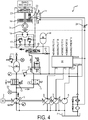
- an exemplary HSD assembly 1 may include a prime mover 2 (e.g., a diesel engine), a hydraulic swing pump 3, a hydraulic swing motor 16, a hydraulic accumulator 10, and a hydraulic tank/reservoir 7 accompanied by various control valves.
- the illustrated HSD assembly includes a swing control valve assembly (here depicted as a single swing control spool valve) 15, a dump valve 14, an isolation valve 13, an accumulator control valve 12.
- HSD hydraulic circuits may be arranged such that in a retarding mode, the hydraulic swing motor 16 acts as a pump and provides a resistive torque to the swing machinery.
- the swing control valve 15 directs the high pressure flow to the hydraulic accumulator 10, the swing pump 3, and/or the dump valve 14. In this mode, the swing pump 3 could thereby act as a motor by converting hydraulic flow into mechanical movement.
- the isolation valve 13 may be used to separate the swing pump/motor 3 and the hydraulic accumulator 10 from the rest of the system for safety reasons and/or to allow use of the swing pump 3 and accumulator 10 simultaneously with braking the swing motor 16 via the dump valve 14.
- the accumulator control valve 12, in braking modes, may be used to ensure a nearly equal pressure drop from the high pressure flow to both the swing pump/motor 3 and the hydraulic accumulator 10.
- the accumulator control valve 12 may be used to control the pressure of the fluid directed to the swing motor 16 when accelerating.
- Recovered energy can be stored in the hydraulic accumulator 10 as pressure for later use and/or transferred back to the engine shaft through the swing pump 3 to supplement the engine power going to accessories or other work functions.
- the dump valve 14 can be used to set the pressure instead of the accumulator 10 and accumulator valve 12; the balance of the energy that cannot be recovered by the engine shaft or the accumulator would be dissipated by the dump valve in an operation similar to that of conventional systems.
- the built up pressure in the hydraulic accumulator 10 can then be used to propel the swing upon the next operator command.
- the swing pump 3 and the swing control valve 15, with possible additional flow from the hydraulic accumulator 10, are used to control the propulsion of the swing function.
- the swing control valve 15 may shift to connect the high pressure flow of the swing pump/motor 3 and possibly the hydraulic accumulator 10 to the appropriate side of the swing motor 16 to turn the swing machinery 1.
- a relief valve 11 for the hydraulic accumulator 10 may be included.
- a relief valve 17 on either side of the swing motor 16 in optional combination with anti-cavitation check valves 18 may be provided.
- the anti-cavitation check valves 18 direct flow back to the swing motor 16 from both the make-up port (connected to the drain line) and the flow dissipated through the swing relief valves 17.
- a low pressure accumulator 39 can be connected to the tank port on the swing control valve 11.
- the low pressure accumulator 39 is charged when the swing motor 16 is being powered by either the accumulator 10 or the swing pump/motor 3.
- the low pressure accumulator check valve 40 prevents flow to the hydraulic reservoir 7 until its cracking pressure has been achieved in the low pressure accumulator 39.
- the swing brake 19 may be actuated via a hydraulic pilot signal from the swing control (e.g., a joystick or the like), resulting in it being released when the swing control is displaced from the zero position and it is applied when the swing control is in the neutral position.
- the swing brake valve on exemplary machines may have a built-in delay function that delays the application of the swing brake 19. This delay may be implemented mechanically, electrically, or via software.
- Exemplary systems may use a solenoid operated swing brake valve 21 which is actuated via a signal from a controller.
- the delay function may be implemented by adding swing brake delay valve 24, an adjustable orifice, to the line that connects the rod side of the swing brake actuator 23 and the hydraulic reservoir 7.
- the spring on the piston side of the swing brake actuator 23 will begin extending the swing brake actuator 23, reducing the volume of the rod side, and therefore displacing fluid out of the swing brake actuator and through the swing brake delay valve 24 to the hydraulic reservoir 7.
- the orifice size through the swing brake delay valve 24 and the flow from the rod side of the swing brake actuator 23 will set the pressure in the rod side of the swing brake actuator 23 which will determine the length of delay from the shift of the swing brake valve 21 to the application of the swing brake 19.
- Figures 2 to 12 describe the modes of operation of the present invention broken down by the type of motion: swing drive propulsion, swing drive retardation, no movement of swing drive.
- dark arrows indicate a use or dissipation of power while light arrows indicate the flow of power that is being recovered. Please note that, for ease of understanding, all of the figures assume the swing machinery is rotating in the same direction.
- Figure 2 illustrates the mode where the swing motor 16 is solely propelled by the swing pump/motor 3; the dark arrows in the figure is used to illustrate the direction of power flow.
- the swing pump/motor 3 is brought on stroke and the swing control valve 15 is shifted to connect the high pressure flow to the appropriate/desired side of the swing motor 16.
- the displacement of the swing pump/motor, and therefore flow, may be used to control the swing speed.
- the isolation valve 13 remains in the open position, and the accumulator control valve 12 remains in the closed position.
- a second mode of propulsion uses solely the hydraulic accumulator 10 and is illustrated in Figure 3 where the accumulator control valve 12 is energized to allow high pressure flow from the hydraulic accumulator 10 to the swing motor 16.
- the accumulator control valve 12 is controlled so that a specified pressure is achieved across the swing motor 16. This results in a known torque and, given a moment of inertia, a known angular acceleration.
- the accumulator control valve 12 can be controlled based on the pressure measured by the pump pressure sensor 29 to achieve/maintain the required pressure across the swing motor 16.
- the swing control valve 15 is energized to connect the high pressure flow to the appropriate side of the swing motor 16 and the swing pump/motor 3 is brought to 0% displacement.
- the isolation valve 13 remains in the open position and the dump valve 14 is energized to be in the closed position.
- the opening of the accumulator control valve 12 is determined based on the desired angular speed of the swing machinery 1 , the measured angular speed of the swing machinery 1 reported by the swing speed sensor 34, and the torque required to accelerate the swing drive.
- FIG. 4 The final configuration used to propel the swing drive is illustrated in Figure 4 where both the hydraulic accumulator 10 and the swing pump/motor 3 are used to provide flow.
- the accumulator control valve 12 is opened and the swing pump/motor 3 is brought on stroke.
- the swing control valve 15 is energized to allow the flow to go to the correct side of the swing motor 16; also note that the isolation valve 13 remains in the open position and the dump valve 14 is energized to the closed position, if the dump valve is included in the system.
- the accumulator control valve 12 will be energized before the swing pump/motor 3 is stroked on so as to minimize the pressure spike required to begin turning the swing drive.
- the swing angular speed is controlled by controlling the pressure across the swing motor 16, which will control the torque applied to movement of the swing machinery 1.
- This angular speed may be controlled mostly by the swing pump/motor 3 and partially by the hydraulic accumulator 10, but the direction of rotation is solely determined by the swing control valve 15. It is noted that, by shifting the swing control valve 15 the opposite direction from that illustrated in Figures 2-4 , the swing pump motor 16 and swing machinery 1 would rotate in the opposite direction.
- the swing pump/motor 3 and/or the accumulator 10 When the swing drive is being accelerated, the swing pump/motor 3 and/or the accumulator 10 will be used. However, when rotating at a constant speed, it is preferable to use the swing pump/motor 3 as the pressure across the swing motor 16 will be minimal. If the accumulator 10 were used when rotating at a constant speed a large portion of the energy in the flow from the accumulator 10 would be dissipated across the accumulator control valve leading to a relatively inefficient use of energy.
- a benefit of decoupling the swing function from the main pumps 5 is that the metering losses through the main swing valve 35 will be reduced.
- a typical system may have the swing function on the same pump as the boom and arm functions. Unfortunately, the required pressure for each of those functions is not always the same, and therefore the flow from the single pump powering those functions must be metered down to each function's required pressure.
- By decoupling the swing function from the main pump the amount of flow that must be metered is reduced, and there is also one less function which can set the operating pressure for the pump.
- the metering losses from the swing pump/motor 3 may be negligible when accelerating the swing machinery 1 because the path from the swing pump/motor 3 to the swing motor 16 may be controlled with on-off valves which direct the flow without metering it. In other words, there are no flow restrictions in the path from the swing pump/motor 3 to the swing motor 16.
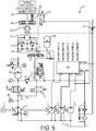
- FIG. 5 illustrates the case where the accumulator 10 is used to decelerate the swing machinery.
- the swing control valve 15 shifts so as to connect the previously low pressure side of swing motor 16, now operating as a pump, to the high pressure side of the circuit.
- the swing pump/motor 3 is de-stroked to prevent flow from going to that part of the circuit.
- the accumulator control valve 12 is preferably fully shifted to the open position to connect the hydraulic accumulator 10 to the high pressure side of the swing motor 16 creating a pressure drop across swing motor 16 generating a torque to retard the motion of the swing machinery.
- the accumulator control valve 12 flow area may be proportionally reduced to create a higher pressure drop across the swing motor 16, but this would reduce the amount of swing energy that can be captured.
- the pressure drop required across the swing motor 16 is determined from the required rate of deceleration and the moment of inertia of the swing drive. When braking with the accumulator 10, the required pressure drop across the swing motor 16 must be equal to the pressure in the accumulator 10 plus the pressure drop across the accumulator control valve 12 minus the pressure of the low pressure accumulator 39.
- the area opening of the accumulator control valve 12 can be calculated by knowing the required pressure drop across it as well as the flow from the swing motor 16 as computed, for example, via the measurements from the swing speed sensor 34.
- the dump valve 14 is energized to be in the closed position, and the isolation valve 13 remains in the open position.
- the accumulator control valve 12 would not be necessary would be if the accumulator 10 was large enough and the pre charge high enough where the accumulator 10 pressure was always "close enough" to the required braking pressure. This would entail an accumulator 10 that could absorb one or more swing cycles where the pressure would not change dramatically while filling with fluid. To more easily and more economically achieve this goal the accumulator 10 could be realized by either using multiple accumulators 10 or an accumulator 10 composed of a traditional accumulator 10 connected to a gas bottle. Having multiple accumulators 10 would increase the amount of energy that can be stored. An accumulator 10 with a gas bottle would allow for a very large volume of gas, at a high pre-charge, where stored energy, or a reduction in gas volume, would not lead to a huge increase in pressure.
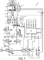
- the swing drive energy is slowed down by providing a resistive torque via the swing motor 16 acting as a pump generating a flow at pressure.
- the pressurized flow is directed through the swing pump/motor 3 which is stroked over centre to function as a motor, thus providing power to the shaft of the main pump 5.
- the main pump/motor 5 in turn creates a pressurized flow that can be used to power other functions connected to the main pump (for example, boom, bucket, arm, etc.).
- the pressure drop across the swing motor 16 may be controlled by varying the swash angle of the swing pump/motor 3 (which, in this case, is depicted as a hydraulically controlled variable displacement pump, but may be any suitable type including, for example, an electronically controlled displacement pump) and the opening of the dump valve 14.
- the amount of flow directed over the dump valve 14 is controlled by the swash angle of the swing pump/motor 3 and the pressure drop is controlled by the dump valve.
- the pressure drop across the dump valve 14 and the pressure drop across the swing pump/motor 3 are the same because they are in parallel.
- the flow to the dump valve 14 is wasted energy, but this can be minimal, as only a small amount of flow may be directed there.
- the distribution of flow between the swing pump/motor 3 and the dump 14 will be dictated by the amount of power the engine shaft can absorb as reported by the engine control unit.
- the power recovered by the engine shaft is directly proportional to the swing pump/motor 3 pressure drop, rotational speed, and displacement; the pump displacement being the most readily available variable to change.
- the flow to the swing pump/motor can be calculated using the engine 2 speed. Because the total flow from the swing motor 16 is known, due to the swing speed sensor 34, the flow through the dump valve 14 can be determined.
- the isolation valve 13 remains in the open position, and the accumulator control valve 12 remains in the closed position.
- the pump/motor 3 can be used recover energy back to the mains pumps 5, but instead of using the dump valve 14 to set the pressure, the swing relief valves 17 can instead be used to set the pressure.
- the pump/motor would be set to a swash angle where the pressure, as measured by the pump pressure sensor 29, is equal to the relief valve setting.
- the maximum (negative) swing pump/motor 3 angle would be dictated by the amount of energy the main pumps 5 can recover, as reported by the engine control module. In this case some flow would be wasted, but through the swing relief valves 17 as opposed to the dump valve 14.
- This mode of operation offers a benefit: the dump valve 14 may not need to be included in the system, resulting in lower cost and more robust control as it requires one fewer component to control in tandem with other components.
- Figure 7 illustrates the situation where both the swing pump/motor 3 and the hydraulic accumulator 10 are used to retard the swing motion of the swing machinery. This mode of braking will occur when the other functions on the machine are operating, and the accumulator pressure is less than the required braking pressure.
- the pressure differential across the swing motor 16 controls the torque, and therefore the deceleration rate.
- the pressure differential across the swing motor is set by the pressure of the accumulator 10 plus the pressure drop across the accumulator control valve 12.
- the distribution of flow, and therefore power, between the accumulator 10 and the swing pump/motor 3 is determined by the current load on the engine; the engine may not recover more energy than it is supplying or else possible damage and other negative consequences may occur.
- the accumulator control valve 12 flow area and the swing pump/motor 3 are adjusted to obtain the required pressure drop and flow distribution to maximize the recovered energy.
- the operation in Figure 7 requires only a portion of the flow to be metered, and even then only some of the pressure is dissipated before it is stored in the hydraulic accumulator 10.
- the isolation valve 13 remains in the open position and the dump valve 14 is energized to be in the closed position.
- FIG. 8 shows the braking of the swing motor 16 via the dump valve 14, while at the same time the swing pump/motor 3 is stroked to charge the accumulator 10.
- the accumulator control valve 12 is opened to connect the hydraulic accumulator 10 to the swing pump/motor 3.
- Figure 10 shows braking via the dump valve 14 as in Figures 8 and 9 .
- the swing pump/motor 3 is de-stroked to 0% displacement, and the accumulator control valve 12 remains closed.
- One shown in Figure 11 , involves using the swing pump/motor 3 to charge the hydraulic accumulator 10 if the charge was incomplete during braking.
- the accumulator charging can occur whether other functions are being performed or not, and there should not be a hydraulic efficiency degradation as the hydraulic accumulator 10 is on a separate circuit from the other work functions. If the hydraulic accumulator 10 is fully charged when the swing operation begins, it can be used to provide the initial torque necessary to accelerate the swing machinery.
- the power required from the engine 2 to charge the hydraulic accumulator 10 can be varied by adjusting the swash angle of the swing pump/motor 3.
- the pressure of the swing pump/motor 3 is set by the pressure of the accumulator, but the fill rate, a product of the flow rate from the swing pump/motor 3, of the accumulator can be controlled by varying the swash angle of the swing pump/motor 3. In the case of a high demand from the engine, this pressure can also be used to aid the movement of other functions as seen in Figure 12 .
- the isolation valve 13 is energized to be in the closed position.
- the accumulator 10 can be used to supplement the engine 2 when the main pumps 5 are driving other functions such as the boom, arm, or bucket. This will reduce the amount of power from the engine and allow for more intelligent power control by operating at a more efficient operating point. Further, when the engine power is at a peak demand the accumulator 10 can be used to shave the power peaks, or load level, so there are not sudden increases in engine power demand. Further, the engine can be managed in a more intelligent way by varying the engine speed to operate at a more efficient point for the current operation. For example, when the power demand is lower the speed of the engine can be decreased while operating at a higher torque which often leads to greater engine efficiency.
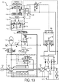
- FIG. 13 depicted is another exemplary HSD system shown at 101.
- the HSD is substantially the same as the above -referenced HSD 1, and consequently the same reference numerals but indexed by 100 are used to denote structures corresponding to similar structures in the HSD.
- the foregoing description of the HSD 1 is equally applicable to the HSD 101 except as noted below.
- aspects of the HSDs may be substituted for one another or used in conjunction with one another where applicable.
- variable displacement pump has been illustrated more explicitly as a hydraulically controlled variable displacement pump (however, this is merely used as an example).
- the pump displacement control valves 104 may include a pressure compensator to limit pressure buildup in the system. This function may alternatively be accomplished with a pressure relief valve on the main hydraulic line.
- FIG. 14 to 38 depicted is another exemplary HSD system shown at 201.
- the HSD is similar to the above -referenced HSD 1 and HSD 101 , and consequently the same reference numerals but indexed by 100 are used to denote structures corresponding to similar structures in the HSD.
- the foregoing description of the HSD 1 and HSD 101 are equally applicable to the HSD 101 except as noted below.
- aspects of the HSDs may be substituted for one another or used in conjunction with one another where applicable.
- the two selection valves 226, 227 are used to direct flow to/from the swing motor 216 to connect to the main pump/motor 205, swing pump/motor 203,and/or the hydraulic accumulator 210.
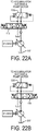
- the swing control valves 228 are a configuration of four two way, two position proportional valves for independent metering of the pressure to or from the pump/motors 205, 203, 216 and/or accumulator 210 as seen in Figures 21A and 21B . Also shown is the use of an isolation valve 220 used to isolate the accumulator 210 from the system.
- Figures 15 and 16 depict two powering modes using only the swing pump/motor 203 or only the hydraulic accumulator 210, respectively.
- the isolation valve 220 and both selection valves 226, 227 should be disengaged.
- the swing pump/motor 203 should be disengaged so no flow is allowed through that branch.
- both selection valves 226, 227 and the isolation valve 220 may be active to provide a connection to the accumulator 210.
- an important factor is controlling the pressure across the swing motor 216 through the use of swing pump/motor 203 displacement and the proportional swing control valves 228.
- the swing pump/motor 216 turns the swing pump/motor 203 which provides extra torque to the main shaft. This torque can be used to provide flow to a different function powered by the main pump/motor 205.
- This mode can be achieved by disengaging both selection valves 226, 227 and leaving the main swing valve 218 in its neutral state.
- the isolation valve 220 should also be disengaged. This mode provides no energy storage, but rather provides energy for immediate use in the system.
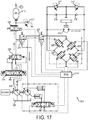
- FIG 17 the same setup is illustrated for swing braking with storage to the hydraulic accumulator 210.
- This storage is achieved by engaging the primary selection valve 226, disengaging the secondary selection valve 227, and opening the isolation valve 220.
- the main swing valve 218 should be actuated to either side to provide flow from the main pump/motor 205 to the accumulator 210.
- the third mode of swing braking is sending the hydraulic pressure directly to the accumulator 210.
- both selection valves 226, 227 are actuated, as well as the isolation valve 220, and the swing pump/motor 203 is set to 0% displacement.
- the main swing valve 218 should be in the neutral position to force all of the flow to the accumulator 210 in the system.
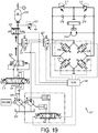
- Figure 19 provides a connection from the main pump/motor 205 by actuating the main swing valve 218, actuating the primary selection valve 226, and by opening the isolation valve 220.
- the secondary selection valve 227 should be disengaged and the swing pump/motor 203 should be disengaged to limit the flow to the accumulator 210 alone.
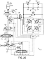
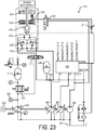
- Figure 20 provides a connection between the secondary pump/motor 203 by disengaging the main swing valve 218 and engaging both selection valves 226, 227.
- the isolation valve 220 should also be engaged and all four swing control valves 228 should be disengaged to provide all of the flow to the accumulator 210.
- Figures 21A and 21B show in detail how to change direction for the swing pump/motor 216 using the swing control valves 228.
- the top left valve is open to fluidly connect a first side of the swing pump/motor 216 to a pressure source, while the lower right valve is open to fluidly connect the second side of the swing pump/motor 216 to tank 207.
- the top right valve is open to fluidly connect the second side of the swing pump/motor 216 to a pressure source, while the lower left valve is open to fluidly connect the first side of the swing pump/motor 216 to tank 207.
- a bank of pilot operated check valves as depicted in Figure 24 , can be used.
- Exemplary embodiments with a bank of pilot operated check valves would allow the swing motor ports to change being connected to pump and then the tank (or vice versa) more quickly as there would be no need to go through a "middle" or neutral position.
- the actuation of these embodiments could also be quicker because the mass of the moving valve member (e.g., balls) would be significantly less than the mass of a large directional control valve spool.
- these embodiments may have the closed centre swing control valve 415 function built in, and, therefore, inclusion of the dump valve 414 would not be necessary.
- a P-A pilot-operated check valve (CV) 436 is disposed between the swing pump and a first side of the swing motor.
- the P-A CV 436 faces the pump (as used herein, a check valve is said to face the direction in which pressurized fluid is allowed to pass without a pilot signal).
- a P-B CV 439 is disposed between the swing pump and a second side of the swing motor.
- the P-B CV 439 faces the pump.
- An A-T CV 438 is disposed between the first side of the swing motor and a reservoir and faces the swing motor.
- a B-T CV 435 is disposed between the second side of the swing motor and the reservoir and faces the swing motor.
- a P-A pilot valve 434 is controllable to supply a pilot signal to the P-A CV 436 and the B-T CV 435 from the pump when energized.
- a P-B pilot valve 437 is controllable to supply a pilot signal to the A-T CV 438 and the P-B CV 439 when energized.
- the pilot 34 that was previously actuated may simply be de-energized and the natural tendency of the check valves will direct the flow and lead to braking.
- the P-B pilot can be actuated at this time, preferred embodiments allow the CV to act naturally to direct the flow.
- the isolation valve is opened, whereas to brake using the swing relief valves the isolation valve is closed.
- the P-B CV 437 actuator is instead used to shift the A-T check valve 38 and the P-B check valve 439.
- the electronic controller module (ECM) 244 may receive signals from various sensors and controls (e.g., the swing control/joystick), process these input signals, and generate control signals to control the position of the electrically controlled valves of the system.
- an internal combustion engine may drive the electronically or mechanically controlled hydraulic pump which is used to power hydraulic components.
- the engine speed is set manually by the operator or controller programmer.
- the engine controller uses speed feedback control in order to maintain the engine at a predefined target speed.
- the engine speed regulator of the injection pump is set by a lever which is pivoted by a piston-cylinder unit.
- the engine controller controls the opening of the fuel throttle valve to determine the output torque. The torque may be adjusted by the displacement of the pump according to the power demand of the hydraulic system.
- the engine can be automatically brought to idle state and can even be turned off automatically to save energy.
- ICE shut-down which is done in a manner as to not take away from the usability of the machine
- the system is designed so that the hydraulic pump-motor can be used to rapidly restart the ICE.
- This pump-motor is much more durable than a standard starter on a typical ICE, providing lower maintenance costs in the long run.
- Exemplary methodologies or portions thereof may be implemented as processor executable instructions or operations provided on a computer-readable medium (for example the ECM 244).
- a computer-readable medium may store processor executable instructions operable to perform a method that includes one or more of the steps described above.
- Computer-readable medium refers to a medium that participates in directly or indirectly providing signals, instructions or data.
- a computer-readable medium may take forms, including, but not limited to, non-volatile media, volatile media, and transmission media.
- Non-volatile media may include, for example, optical or magnetic disks, and so on.
- Volatile media may include, for example, optical or magnetic disks, dynamic memory and the like.
- Transmission media may include coaxial cables, copper wire, fibre optic cables, and the like. Transmission media can also take the form of electromagnetic radiation, like that generated during radio-wave and infra-red data communications, or take the form of one or more groups of signals.
- a computer-readable medium include, but are not limited to, a floppy disk, a flexible disk, a hard disk, a magnetic tape, other magnetic media, a CD-ROM, other optical media, punch cards, paper tape, other physical media with patterns of holes, a RAM, a ROM, an EPROM, a FLASH-EPROM, or other memory chip or card, a memory stick, a carrier wave/pulse, and other media from which a computer, a processor or other electronic device can read.
- Signals used to propagate instructions or other software over a network like the Internet, can be considered a "computer-readable medium".
- Software includes but is not limited to, one or more computer or processor instructions that can be read, interpreted, compiled, or executed and that cause a computer, processor, or other electronic device to perform functions, actions or behave in a desired manner.
- the instructions may be embodied in various forms like routines, algorithms, modules, methods, threads, or programs including separate applications or code from dynamically or statically linked libraries.
- Software may also be implemented in a variety of executable or loadable forms including, but not limited to, a stand-alone program, a function call (local or remote), a servelet, an applet, instructions stored in a memory, part of an operating system or other types of executable instructions.
- Suitable software for implementing the various components of the example systems and methods described herein may be produced using programming languages and tools like Java, Java Script, Java.NET, ASP.NET, VB.NET, Cocoa, Pascal, C#, C++, C, CGI, Perl, SQL, APIs, SDKs, assembly, firmware, microcode, or other languages and tools.
- Software whether an entire system or a component of a system, may be embodied as an article of manufacture and maintained or provided as part of a computer-readable medium as defined previously. Other forms may also be used.
- Signal includes but is not limited to one or more electrical or optical signals, analog or digital signals, data, one or more computer or processor instructions, messages, a bit or bit stream, or other means that can be received, transmitted or detected.
- Exemplary HSDs may thus provide a number of advantages over conventional hydraulic excavators and conventional electric hybrid excavators (EHEs).
- EHEs electric hybrid excavators
- HSDs may use existing fixed displacement swing motor with added hydraulic motor/pump, together with an energy storage device, to recover kinetic energy from the braking operation of machine upper structure and reduce the metering losses resulting in better fuel economy than conventional vehicles.
- HSDs may increase the effective productivity of the vehicle by using stored energy to perform swing operations and thus allowing more of the engine power to be used for other functions.
- HSDs provide a reliable and seamless transition of machine upper structure acceleration and braking operation.
- HSDs may assist engine power by using stored brake energy to provide more smooth and efficient operation of hydraulic actuation functions.
- Fifth, HSDs may lower cooling requirements compared to conventional machines due to reduced heat generation from fluid throttling across a swing valve and valves of other functions.
- HSDs may allow for optimized engine operation through engine management: the presence of an accumulator as an auxiliary energy source can be utilized to manage the engine more efficiently for a given power demand, and by using advanced control which actively controls the engine speed and torque independently through intelligent control of the pump displacement, the engine may be controlled to its most efficient points, thereby significantly improving fuel economy.
- HSDs may reduce the engine size required for a given application by using accumulator or swing power to supplement engine power with hydraulic power to thereby level the peak load experienced by the engine.
- exemplary HSDs are lower cost than systems in which the fixed displacement motor attached to the swing drive machinery is replaced with a variable unit. Further, using a directional control valve to control the direction of flow and the pressure drop across the motor is also a lower cost solution than a series of independent meter valves. Additionally, there will be less flow losses because the flow in exemplary systems is directed through fewer valves. There is also the option of controlling the swing brake 19, to override the activation, preventing unnecessary wear using the swing brake override valve 21.
Landscapes
- Engineering & Computer Science (AREA)
- General Engineering & Computer Science (AREA)
- Mining & Mineral Resources (AREA)
- Civil Engineering (AREA)
- Structural Engineering (AREA)
- Physics & Mathematics (AREA)
- Fluid Mechanics (AREA)
- Mechanical Engineering (AREA)
- Chemical & Material Sciences (AREA)
- Analytical Chemistry (AREA)
- Fluid-Pressure Circuits (AREA)
- Operation Control Of Excavators (AREA)
Claims (15)
- Système d'entraînement en oscillation hybride (1) pour une utilisation dans une machine de construction, comprenant :une pompe hydraulique oscillante à cylindrée variable (3) pouvant fonctionner par un moteur principal (2),un moteur hydraulique oscillant (16) pour effectuer une fonction d'oscillation de la machine,un accumulateur (10),un dispositif de commande (244),un ensemble de soupape de commande d'oscillation (15) disposé dans un premier chemin hydraulique s'étendant depuis la pompe hydraulique oscillante vers le moteur hydraulique oscillant, l'ensemble de soupape de commande d'oscillation ayant une première position reliant de manière fluidique la pompe hydraulique oscillante à un premier côté du moteur hydraulique oscillant et une deuxième position reliant de manière fluidique la pompe hydraulique oscillante à un deuxième côté du moteur hydraulique oscillant, etune soupape de commande d'accumulateur (12) ayant une position ouverte reliant de manière fluidique l'accumulateur au premier chemin hydraulique au niveau d'un point de connexion de soupape de commande d'accumulateur et une position fermée isolant de manière fluidique l'accumulateur du premier chemin hydraulique,où le dispositif de commande (244) est configuré dans un mode de fonctionnement pour diriger l'écoulement depuis le moteur hydraulique oscillant (16) vers l'accumulateur (10), et le dispositif de commande est configuré dans un autre mode de fonctionnement pour diriger l'écoulement depuis l'accumulateur (10) vers le moteur hydraulique oscillant (16),caractérisé en ce que le dispositif de commande (244) est configuré dans un autre mode de fonctionnement pour diriger l'écoulement depuis le moteur hydraulique oscillant (16) vers la pompe hydraulique oscillante (3), etle dispositif de commande est configuré dans un autre mode de fonctionnement pour diriger l'écoulement depuis l'accumulateur (10) vers la pompe hydraulique oscillante (3), etle dispositif de commande est configuré dans un autre mode de fonctionnement pour diriger l'écoulement depuis la pompe hydraulique oscillante (3) vers l'accumulateur (10).
- Système d'entraînement en oscillation hybride de la revendication 1, dans lequel l'ensemble de soupape de commande d'oscillation (15) comporte un premier clapet antiretour piloté (436) disposé entre la pompe hydraulique oscillante (3) et un premier côté du moteur hydraulique oscillant (16) et faisant face à la pompe hydraulique oscillante, et un deuxième clapet antiretour piloté (439) disposé entre la pompe hydraulique oscillante et un deuxième côté du moteur hydraulique oscillant et faisant face à la pompe,
et où le système d'entraînement en oscillation hybride comporte en outre un troisième clapet antiretour piloté (439) disposé entre le premier côté du moteur hydraulique oscillant et un réservoir et faisant face au moteur oscillant, et un quatrième clapet antiretour piloté (435) disposé entre le deuxième côté du moteur oscillant et le réservoir et faisant face au moteur. - Système d'entraînement en oscillation hybride de la revendication 1 ou 2, dans lequel l'écoulement depuis le moteur hydraulique oscillant (16) vers la pompe hydraulique oscillante (3) n'est pas mesuré.
- Système d'entraînement en oscillation hybride de l'une des revendications précédentes, dans lequel l'écoulement depuis le moteur hydraulique oscillant (16) vers l'accumulateur (10) n'est pas mesuré.
- Système d'entraînement en oscillation hybride de l'une des revendications précédentes, comprenant en outre une soupape de décharge doseuse (14) configurée pour relier de manière fluidique sélectivement le premier chemin hydraulique à un orifice de réservoir.
- Système d'entraînement en oscillation hybride de l'une des revendications précédentes, comprenant en outre une soupape d'isolement (13) disposée dans le passage de fluide entre le point de connexion de soupape de commande d'accumulateur et l'ensemble de soupape de commande d'oscillation (15), la soupape d'isolement ayant une position ouverte reliant de manière fluidique la pompe hydraulique oscillante (3) au moteur hydraulique oscillant (16), et une position fermée isolant de manière fluidique l'accumulateur (10) et la pompe oscillante du moteur oscillant.
- Système d'entraînement en oscillation hybride de l'une des revendications précédentes, dans lequel le dispositif de commande (244) est configuré pour ouvrir la soupape de commande d'accumulateur (12) et pour désengager la pompe hydraulique oscillante (3).
- Système d'entraînement en oscillation hybride de la revendication 5, dans lequel le dispositif de commande (244) est configuré pour fermer la soupape de commande d'accumulateur (12), pour mesurer l'écoulement à travers la soupape de décharge doseuse (14) et pour engager la pompe hydraulique oscillante (3) pour une utilisation en tant que moteur.
- Système d'entraînement en oscillation hybride de l'une des revendications précédentes, dans lequel le dispositif de commande (244) est configuré pour fermer la soupape de commande d'accumulateur (12) et pour engager la pompe hydraulique oscillante (3) pour une utilisation en tant que moteur, et dans lequel une soupape de sûreté de système (11) est configurée pour permettre à l'écoulement excessif de passer dans le réservoir.
- Système d'entraînement en oscillation hybride de la revendication 9, dans lequel le dispositif de commande (244) est configuré pour régler un angle d'oscillation de la pompe hydraulique oscillante (3) de sorte que la pression au niveau de la pompe hydraulique oscillante soit égale à une pression d'ouverture de la soupape de sûreté de système (11).
- Système d'entraînement en oscillation hybride de la revendication 6, dans lequel le dispositif de commande (244) est configuré pour ouvrir la soupape de commande d'accumulateur (12), pour fermer la soupape d'isolement (13), et pour engager la pompe hydraulique oscillante (3) pour une utilisation en tant que pompe, et dans lequel une soupape de sûreté de système (11) est configurée pour permettre à l'écoulement excessif de passer dans le réservoir.
- Système d'entraînement en oscillation hybride de la revendication 6, dans lequel le dispositif de commande (244) est configuré pour ouvrir la soupape de commande d'accumulateur (12), pour fermer la soupape d'isolement (11), et pour engager la pompe hydraulique oscillante (3) pour une utilisation en tant que moteur, et dans lequel une soupape de sûreté de système (11) est configurée pour permettre à l'écoulement excessif de passer dans le réservoir.
- Système d'entraînement en oscillation hybride de l'une des revendications précédentes, dans lequel le moteur principal (2) est un moteur à combustion interne et le dispositif de commande (244) est configuré pour surveiller la vitesse moteur et le couple moteur, pour comparer la vitesse moteur et le couple moteur à des données de rendement, et pour ajuster la vitesse moteur et ajuster la cylindrée de la pompe hydraulique oscillante (2), et ainsi le couple moteur, sur la base de la comparaison.
- Système d'entraînement en oscillation hybride de l'une des revendications précédentes, dans lequel le dispositif de commande (244) est configuré pour arrêter le moteur principal (2) pendant le fonctionnement du système d'entraînement.
- Système d'entraînement en oscillation hybride de l'une des revendications précédentes, comprenant en outre un accumulateur basse pression (39) disposé entre un réservoir et le moteur hydraulique oscillant (16) et configuré pour éviter la cavitation dans le système d'entraînement.
Applications Claiming Priority (2)
| Application Number | Priority Date | Filing Date | Title |
|---|---|---|---|
| US201361758523P | 2013-01-30 | 2013-01-30 | |
| PCT/US2014/013861 WO2014120930A1 (fr) | 2013-01-30 | 2014-01-30 | Système d'entraînement à bascule hybride hydraulique pour excavateurs |
Publications (2)
| Publication Number | Publication Date |
|---|---|
| EP2951359A1 EP2951359A1 (fr) | 2015-12-09 |
| EP2951359B1 true EP2951359B1 (fr) | 2017-10-04 |
Family
ID=50116179
Family Applications (1)
| Application Number | Title | Priority Date | Filing Date |
|---|---|---|---|
| EP14705256.7A Active EP2951359B1 (fr) | 2013-01-30 | 2014-01-30 | Système d'entraînement à bascule hybride hydraulique pour excavateurs |
Country Status (4)
| Country | Link |
|---|---|
| US (1) | US10024341B2 (fr) |
| EP (1) | EP2951359B1 (fr) |
| CN (1) | CN105074093B (fr) |
| WO (1) | WO2014120930A1 (fr) |
Families Citing this family (37)
| Publication number | Priority date | Publication date | Assignee | Title |
|---|---|---|---|---|
| GB2528321A (en) * | 2014-07-18 | 2016-01-20 | Airbus Operations Ltd | Determining integrity of braking control system |
| JP6563182B2 (ja) * | 2014-08-29 | 2019-08-21 | 住友重機械工業株式会社 | 建設機械 |
| KR102393674B1 (ko) * | 2014-10-06 | 2022-05-02 | 스미도모쥬기가이고교 가부시키가이샤 | 쇼벨 |
| CN104712603B (zh) * | 2015-03-18 | 2016-12-07 | 徐州重型机械有限公司 | 一种汽车起重机的液压系统、汽车起重机及控制方法 |
| US9809958B2 (en) | 2015-03-25 | 2017-11-07 | Caterpillar Inc. | Engine assist by recovering swing kinetic energy |
| KR102483963B1 (ko) * | 2015-03-27 | 2022-12-30 | 스미도모쥬기가이고교 가부시키가이샤 | 쇼벨 및 쇼벨의 구동방법 |
| RU2720393C2 (ru) | 2015-05-28 | 2020-04-29 | ДЖОЙ ГЛОБАЛ ЛОНГВЬЮ ОПЕРЕЙШНЗ ЭлЭлСи | Погрузочная машина и способ её эксплуатации |
| CN112627281A (zh) | 2015-08-14 | 2021-04-09 | 派克汉尼芬公司 | 液压挖掘机的动臂势能回收 |
| CN105298993B (zh) * | 2015-10-19 | 2017-04-19 | 太原理工大学 | 机械软启动辅助驱动装置 |
| EP3178778B1 (fr) * | 2015-12-10 | 2019-05-22 | UniCarriers Europe AB | Système hydraulique de régénération d'énergie et véhicule industriel avec ce système hydraulique |
| CN105642808B (zh) * | 2015-12-30 | 2018-04-13 | 二重(德阳)重型装备有限公司 | 辊锻机制动及慢速进给节能装置 |
| US9903395B2 (en) * | 2016-02-24 | 2018-02-27 | Mac Valves, Inc. | Proportional pressure controller with isolation valve assembly |
| WO2017188869A1 (fr) * | 2016-04-28 | 2017-11-02 | Volvo Construction Equipment Ab | Système hydraulique |
| NO343276B1 (en) * | 2016-11-30 | 2019-01-14 | Impact Solutions As | A method of controlling a prime mover and a plant for controlling the delivery of a pressurized fluid in a conduit |
| JP6935122B2 (ja) * | 2017-03-06 | 2021-09-15 | 住友重機械工業株式会社 | 作業機械 |
| WO2018194357A1 (fr) * | 2017-04-18 | 2018-10-25 | 두산인프라코어 주식회사 | Engin de chantier |
| JP6999320B2 (ja) * | 2017-07-26 | 2022-01-18 | 住友建機株式会社 | ショベル |
| JP6891079B2 (ja) * | 2017-09-15 | 2021-06-18 | 川崎重工業株式会社 | 建設機械の油圧駆動システム |
| FI128622B (fi) * | 2017-10-09 | 2020-08-31 | Norrhydro Oy | Hydraulijärjestelmä ja sen ohjausjärjestelmä |
| CN107985281B (zh) * | 2017-10-27 | 2023-04-28 | 吉林大学 | 一种集成液压辅助气制动装置的支撑桥及其控制方法 |
| CN108643276A (zh) * | 2018-06-06 | 2018-10-12 | 马鞍山松鹤信息科技有限公司 | 一种具有能量回收系统的节能型挖掘机 |
| KR102633378B1 (ko) | 2019-02-13 | 2024-02-02 | 에이치디현대인프라코어 주식회사 | 건설 기계 |
| ES2942905T3 (es) * | 2019-02-22 | 2023-06-07 | Clark Equipment Co | Control de tracción para máquina motriz articulada de dirección |
| WO2020180367A1 (fr) | 2019-03-01 | 2020-09-10 | United Technologies Advanced Projects Inc. | Équilibrage de couple pour systèmes de propulsion électrique hybrides et aéronef utilisant des systèmes de propulsion électrique hybrides |
| US11697505B2 (en) | 2019-03-01 | 2023-07-11 | Pratt & Whitney Canada Corp. | Distributed propulsion configurations for aircraft having mixed drive systems |
| US11628942B2 (en) | 2019-03-01 | 2023-04-18 | Pratt & Whitney Canada Corp. | Torque ripple control for an aircraft power train |
| US11732639B2 (en) | 2019-03-01 | 2023-08-22 | Pratt & Whitney Canada Corp. | Mechanical disconnects for parallel power lanes in hybrid electric propulsion systems |
| WO2020190344A2 (fr) | 2019-03-18 | 2020-09-24 | United Technologies Advanced Projects Inc. | Architectures pour propulsion hybride électrique |
| CN112343875B (zh) * | 2019-08-07 | 2024-08-20 | 北京康布尔石油技术发展有限公司 | 回转设备液压驱动装置和驱动方法 |
| US11486472B2 (en) | 2020-04-16 | 2022-11-01 | United Technologies Advanced Projects Inc. | Gear sytems with variable speed drive |
| US11198987B2 (en) | 2020-04-24 | 2021-12-14 | Caterpillar Inc. | Hydraulic circuit for a swing system in a machine |
| CN113719485B (zh) * | 2020-05-25 | 2024-10-29 | 中国铁路西安局集团有限公司科学技术研究所 | 一种公铁两用清挖机液压系统 |
| KR102734037B1 (ko) * | 2020-10-19 | 2024-11-26 | 히다치 겡키 가부시키 가이샤 | 건설 기계 |
| US11946225B2 (en) | 2021-05-28 | 2024-04-02 | Caterpillar Inc. | Method and systems for controlling electrically-powered hydraulic circuits |
| CN114295000B (zh) * | 2021-11-24 | 2023-12-15 | 北京航天发射技术研究所 | 一种可快速回收的高可靠性支撑液压系统及支撑方法 |
| CN115478572A (zh) * | 2022-07-29 | 2022-12-16 | 浙江大学 | 工程机械装备及其分布式电动静液压驱动系统 |
| US11753796B1 (en) | 2022-11-17 | 2023-09-12 | Deere & Company | Swing drive with oil management system and work vehicle with same |
Family Cites Families (36)
| Publication number | Priority date | Publication date | Assignee | Title |
|---|---|---|---|---|
| US4662684A (en) | 1979-12-13 | 1987-05-05 | H. B. Zachery Corporation | Rotary rock and trench cutting saw |
| JPS5917074A (ja) * | 1982-07-16 | 1984-01-28 | Hitachi Constr Mach Co Ltd | ロジツク弁 |
| JPS6041602U (ja) | 1983-08-31 | 1985-03-23 | 株式会社小松製作所 | ブレ−キ弁装置 |
| US4906113A (en) | 1988-07-27 | 1990-03-06 | Quintette Coal Limited | Slew ring bearing |
| DE4000830A1 (de) | 1990-01-13 | 1991-07-18 | Orenstein & Koppel Ag | Kugeldrehverbindung fuer bagger, krane oder dgl. |
| US5499503A (en) * | 1994-09-22 | 1996-03-19 | Iowa Mold Tooling Company, Inc. | Hydraulic swing circuit |
| JP3433415B2 (ja) * | 1997-04-21 | 2003-08-04 | アイダエンジニアリング株式会社 | プレス機械のスライド駆動装置 |
| JP3877901B2 (ja) | 1999-03-31 | 2007-02-07 | コベルコ建機株式会社 | ショベル |
| US6502393B1 (en) * | 2000-09-08 | 2003-01-07 | Husco International, Inc. | Hydraulic system with cross function regeneration |
| JP4424844B2 (ja) | 2000-12-13 | 2010-03-03 | 株式会社小松製作所 | 作業機械の旋回減速機 |
| JP4512283B2 (ja) * | 2001-03-12 | 2010-07-28 | 株式会社小松製作所 | ハイブリッド式建設機械 |
| WO2003095751A1 (fr) | 2002-05-09 | 2003-11-20 | Kobelco Construction Machinery Co., Ltd. | Dispositif de commande de rotation sur machine a travailler |
| JP4082935B2 (ja) | 2002-06-05 | 2008-04-30 | 株式会社小松製作所 | ハイブリッド式建設機械 |
| JP2004125094A (ja) * | 2002-10-03 | 2004-04-22 | Komatsu Ltd | 作業車両の油圧システム |
| DE102004030009A1 (de) * | 2004-06-22 | 2006-01-12 | Hydac Electronic Gmbh | Hydraulische Steuervorrichtung |
| US7451685B2 (en) * | 2005-03-14 | 2008-11-18 | Husco International, Inc. | Hydraulic control system with cross function regeneration |
| US7269944B2 (en) * | 2005-09-30 | 2007-09-18 | Caterpillar Inc. | Hydraulic system for recovering potential energy |
| US7234298B2 (en) | 2005-10-06 | 2007-06-26 | Caterpillar Inc | Hybrid hydraulic system and work machine using same |
| JP4524679B2 (ja) | 2006-03-15 | 2010-08-18 | コベルコ建機株式会社 | ハイブリッド建設機械 |
| US8037963B2 (en) | 2006-08-02 | 2011-10-18 | Komatsu Ltd. | Hybrid working vehicle |
| US7690450B2 (en) | 2006-09-12 | 2010-04-06 | Parker-Hannifin Corporation | System for operating a hydraulically actuated device |
| JP5055948B2 (ja) | 2006-10-20 | 2012-10-24 | コベルコ建機株式会社 | ハイブリッド作業機械 |
| JP4946733B2 (ja) * | 2007-02-21 | 2012-06-06 | コベルコ建機株式会社 | 旋回制御装置及びこれを備えた作業機械 |
| WO2008123368A1 (fr) | 2007-03-28 | 2008-10-16 | Komatsu Ltd. | Procédé de commande d'engin de chantier hybride, et engin de chantier hybride |
| US8978798B2 (en) * | 2007-10-12 | 2015-03-17 | Odyne Systems, Llc | Hybrid vehicle drive system and method and idle reduction system and method |
| US7908852B2 (en) | 2008-02-28 | 2011-03-22 | Caterpillar Inc. | Control system for recovering swing motor kinetic energy |
| JP5401992B2 (ja) | 2009-01-06 | 2014-01-29 | コベルコ建機株式会社 | ハイブリッド作業機械の動力源装置 |
| DE202009004071U1 (de) | 2009-03-23 | 2010-08-12 | Liebherr-France Sas, Colmar | Antrieb für einen Hydraulikbagger |
| JP5163593B2 (ja) | 2009-05-25 | 2013-03-13 | コベルコ建機株式会社 | ハイブリッド作業機械 |
| KR101061193B1 (ko) * | 2009-11-12 | 2011-09-01 | 볼보 컨스트럭션 이큅먼트 에이비 | 굴삭기의 선회에너지 회생장치 |
| DE102009053702A1 (de) * | 2009-11-18 | 2011-05-19 | Robert Bosch Gmbh | Schwenkantrieb mit Energierückgewinnung |
| JP5174090B2 (ja) | 2010-06-30 | 2013-04-03 | 日立建機株式会社 | 建設機械の旋回装置 |
| CN103119226B (zh) * | 2010-10-06 | 2016-01-06 | 住友重机械工业株式会社 | 混合式工作机械 |
| BR112013014652A2 (pt) * | 2010-12-13 | 2018-05-15 | Eaton Corp | sistema hidráulico para atuação, método de utilização de um sistema hidráulico, sistema de suspensão hidráulica e método para reusar energia |
| US20120324875A1 (en) * | 2011-06-24 | 2012-12-27 | Caterpillar Inc. | Optimized system response with multiple commands |
| DE102011106715A1 (de) * | 2011-07-06 | 2013-01-10 | Linde Material Handling Gmbh | Hydrostatisches Antriebssystem |
-
2014
- 2014-01-30 EP EP14705256.7A patent/EP2951359B1/fr active Active
- 2014-01-30 CN CN201480019474.9A patent/CN105074093B/zh active Active
- 2014-01-30 US US14/764,794 patent/US10024341B2/en active Active
- 2014-01-30 WO PCT/US2014/013861 patent/WO2014120930A1/fr not_active Ceased
Non-Patent Citations (1)
| Title |
|---|
| None * |
Also Published As
| Publication number | Publication date |
|---|---|
| US20160010663A1 (en) | 2016-01-14 |
| CN105074093B (zh) | 2017-05-10 |
| US10024341B2 (en) | 2018-07-17 |
| WO2014120930A1 (fr) | 2014-08-07 |
| CN105074093A (zh) | 2015-11-18 |
| EP2951359A1 (fr) | 2015-12-09 |
Similar Documents
| Publication | Publication Date | Title |
|---|---|---|
| EP2951359B1 (fr) | Système d'entraînement à bascule hybride hydraulique pour excavateurs | |
| EP3030725B1 (fr) | Système d'entraînement en giration de type hybride et hydraulique pour excavatrices | |
| CN107000564B (zh) | 具有静流体选择的液压混合推进回路以及操作方法 | |
| KR101975062B1 (ko) | 건설기계의 유압시스템 | |
| US9951795B2 (en) | Integration of swing energy recovery and engine anti-idling systems | |
| Hippalgaonkar et al. | A series-parallel hydraulic hybrid mini-excavator with displacement controlled actuators | |
| KR102445784B1 (ko) | 유체정역학 옵션을 구비하는 유압 하이브리드 추진 회로 및 작동 방법 | |
| JP2013151986A (ja) | 回路圧制御装置、この回路圧制御装置を用いた油圧制御回路及び建設機械の油圧制御回路 | |
| US20220307595A1 (en) | Hydraulic circuit architecture with enhanced operation efficency | |
| JP2021532040A (ja) | 荷役車両用の油圧システム | |
| EP3973110B1 (fr) | Procédé de commande d'une charge rotative, système hydraulique et machine de travail | |
| EP3469235B1 (fr) | Transmission hydraulique avec un module secondaire | |
| KR102010592B1 (ko) | 건설기계의 유압시스템 | |
| US12025219B2 (en) | Hydrostatic traction drive in an open circuit | |
| JP2025110899A (ja) | 液圧式の駆動システム、および液圧式の駆動システムを動作させるための方法 | |
| KR20250176530A (ko) | 2개의 유압 회로를 구비한 유압 시스템의 작동 방법 | |
| KR20230125266A (ko) | 유압 장치용 제어기 |
Legal Events
| Date | Code | Title | Description |
|---|---|---|---|
| PUAI | Public reference made under article 153(3) epc to a published international application that has entered the european phase |
Free format text: ORIGINAL CODE: 0009012 |
|
| 17P | Request for examination filed |
Effective date: 20150806 |
|
| AK | Designated contracting states |
Kind code of ref document: A1 Designated state(s): AL AT BE BG CH CY CZ DE DK EE ES FI FR GB GR HR HU IE IS IT LI LT LU LV MC MK MT NL NO PL PT RO RS SE SI SK SM TR |
|
| AX | Request for extension of the european patent |
Extension state: BA ME |
|
| RIN1 | Information on inventor provided before grant (corrected) |
Inventor name: ZHANG, HAO Inventor name: STEGEMANN, PATRICK Inventor name: WHITE, NICK Inventor name: CULLMAN, JEFF Inventor name: COLLETT, RAYMOND Inventor name: HOWLAND, JAMES |
|
| DAX | Request for extension of the european patent (deleted) | ||
| GRAP | Despatch of communication of intention to grant a patent |
Free format text: ORIGINAL CODE: EPIDOSNIGR1 |
|
| RIC1 | Information provided on ipc code assigned before grant |
Ipc: E02F 9/12 20060101AFI20161018BHEP Ipc: F15B 21/14 20060101ALI20161018BHEP Ipc: E02F 9/22 20060101ALI20161018BHEP Ipc: F15B 11/08 20060101ALI20161018BHEP Ipc: E02F 9/20 20060101ALI20161018BHEP Ipc: B66C 23/84 20060101ALI20161018BHEP Ipc: F15B 1/02 20060101ALI20161018BHEP |
|
| INTG | Intention to grant announced |
Effective date: 20161117 |
|
| GRAJ | Information related to disapproval of communication of intention to grant by the applicant or resumption of examination proceedings by the epo deleted |
Free format text: ORIGINAL CODE: EPIDOSDIGR1 |
|
| INTC | Intention to grant announced (deleted) | ||
| GRAJ | Information related to disapproval of communication of intention to grant by the applicant or resumption of examination proceedings by the epo deleted |
Free format text: ORIGINAL CODE: EPIDOSDIGR1 |
|
| GRAS | Grant fee paid |
Free format text: ORIGINAL CODE: EPIDOSNIGR3 |
|
| GRAP | Despatch of communication of intention to grant a patent |
Free format text: ORIGINAL CODE: EPIDOSNIGR1 |
|
| INTG | Intention to grant announced |
Effective date: 20170504 |
|
| GRAA | (expected) grant |
Free format text: ORIGINAL CODE: 0009210 |
|
| AK | Designated contracting states |
Kind code of ref document: B1 Designated state(s): AL AT BE BG CH CY CZ DE DK EE ES FI FR GB GR HR HU IE IS IT LI LT LU LV MC MK MT NL NO PL PT RO RS SE SI SK SM TR |
|
| REG | Reference to a national code |
Ref country code: GB Ref legal event code: FG4D |
|
| REG | Reference to a national code |
Ref country code: CH Ref legal event code: EP |
|
| REG | Reference to a national code |
Ref country code: AT Ref legal event code: REF Ref document number: 934176 Country of ref document: AT Kind code of ref document: T Effective date: 20171015 |
|
| REG | Reference to a national code |
Ref country code: IE Ref legal event code: FG4D |
|
| REG | Reference to a national code |
Ref country code: DE Ref legal event code: R096 Ref document number: 602014015336 Country of ref document: DE |
|
| REG | Reference to a national code |
Ref country code: SE Ref legal event code: TRGR |
|
| REG | Reference to a national code |
Ref country code: FR Ref legal event code: PLFP Year of fee payment: 5 |
|
| REG | Reference to a national code |
Ref country code: NL Ref legal event code: MP Effective date: 20171004 |
|
| REG | Reference to a national code |
Ref country code: LT Ref legal event code: MG4D |
|
| REG | Reference to a national code |
Ref country code: AT Ref legal event code: MK05 Ref document number: 934176 Country of ref document: AT Kind code of ref document: T Effective date: 20171004 |
|
| PG25 | Lapsed in a contracting state [announced via postgrant information from national office to epo] |
Ref country code: NL Free format text: LAPSE BECAUSE OF FAILURE TO SUBMIT A TRANSLATION OF THE DESCRIPTION OR TO PAY THE FEE WITHIN THE PRESCRIBED TIME-LIMIT Effective date: 20171004 |
|
| PG25 | Lapsed in a contracting state [announced via postgrant information from national office to epo] |
Ref country code: ES Free format text: LAPSE BECAUSE OF FAILURE TO SUBMIT A TRANSLATION OF THE DESCRIPTION OR TO PAY THE FEE WITHIN THE PRESCRIBED TIME-LIMIT Effective date: 20171004 Ref country code: LT Free format text: LAPSE BECAUSE OF FAILURE TO SUBMIT A TRANSLATION OF THE DESCRIPTION OR TO PAY THE FEE WITHIN THE PRESCRIBED TIME-LIMIT Effective date: 20171004 Ref country code: FI Free format text: LAPSE BECAUSE OF FAILURE TO SUBMIT A TRANSLATION OF THE DESCRIPTION OR TO PAY THE FEE WITHIN THE PRESCRIBED TIME-LIMIT Effective date: 20171004 Ref country code: NO Free format text: LAPSE BECAUSE OF FAILURE TO SUBMIT A TRANSLATION OF THE DESCRIPTION OR TO PAY THE FEE WITHIN THE PRESCRIBED TIME-LIMIT Effective date: 20180104 |
|
| PG25 | Lapsed in a contracting state [announced via postgrant information from national office to epo] |
Ref country code: RS Free format text: LAPSE BECAUSE OF FAILURE TO SUBMIT A TRANSLATION OF THE DESCRIPTION OR TO PAY THE FEE WITHIN THE PRESCRIBED TIME-LIMIT Effective date: 20171004 Ref country code: LV Free format text: LAPSE BECAUSE OF FAILURE TO SUBMIT A TRANSLATION OF THE DESCRIPTION OR TO PAY THE FEE WITHIN THE PRESCRIBED TIME-LIMIT Effective date: 20171004 Ref country code: AT Free format text: LAPSE BECAUSE OF FAILURE TO SUBMIT A TRANSLATION OF THE DESCRIPTION OR TO PAY THE FEE WITHIN THE PRESCRIBED TIME-LIMIT Effective date: 20171004 Ref country code: HR Free format text: LAPSE BECAUSE OF FAILURE TO SUBMIT A TRANSLATION OF THE DESCRIPTION OR TO PAY THE FEE WITHIN THE PRESCRIBED TIME-LIMIT Effective date: 20171004 Ref country code: IS Free format text: LAPSE BECAUSE OF FAILURE TO SUBMIT A TRANSLATION OF THE DESCRIPTION OR TO PAY THE FEE WITHIN THE PRESCRIBED TIME-LIMIT Effective date: 20180204 Ref country code: GR Free format text: LAPSE BECAUSE OF FAILURE TO SUBMIT A TRANSLATION OF THE DESCRIPTION OR TO PAY THE FEE WITHIN THE PRESCRIBED TIME-LIMIT Effective date: 20180105 Ref country code: BG Free format text: LAPSE BECAUSE OF FAILURE TO SUBMIT A TRANSLATION OF THE DESCRIPTION OR TO PAY THE FEE WITHIN THE PRESCRIBED TIME-LIMIT Effective date: 20180104 |
|
| REG | Reference to a national code |
Ref country code: DE Ref legal event code: R097 Ref document number: 602014015336 Country of ref document: DE |
|
| PG25 | Lapsed in a contracting state [announced via postgrant information from national office to epo] |
Ref country code: EE Free format text: LAPSE BECAUSE OF FAILURE TO SUBMIT A TRANSLATION OF THE DESCRIPTION OR TO PAY THE FEE WITHIN THE PRESCRIBED TIME-LIMIT Effective date: 20171004 Ref country code: SK Free format text: LAPSE BECAUSE OF FAILURE TO SUBMIT A TRANSLATION OF THE DESCRIPTION OR TO PAY THE FEE WITHIN THE PRESCRIBED TIME-LIMIT Effective date: 20171004 Ref country code: CZ Free format text: LAPSE BECAUSE OF FAILURE TO SUBMIT A TRANSLATION OF THE DESCRIPTION OR TO PAY THE FEE WITHIN THE PRESCRIBED TIME-LIMIT Effective date: 20171004 Ref country code: DK Free format text: LAPSE BECAUSE OF FAILURE TO SUBMIT A TRANSLATION OF THE DESCRIPTION OR TO PAY THE FEE WITHIN THE PRESCRIBED TIME-LIMIT Effective date: 20171004 |
|
| PLBE | No opposition filed within time limit |
Free format text: ORIGINAL CODE: 0009261 |
|
| STAA | Information on the status of an ep patent application or granted ep patent |
Free format text: STATUS: NO OPPOSITION FILED WITHIN TIME LIMIT |
|
| PG25 | Lapsed in a contracting state [announced via postgrant information from national office to epo] |
Ref country code: PL Free format text: LAPSE BECAUSE OF FAILURE TO SUBMIT A TRANSLATION OF THE DESCRIPTION OR TO PAY THE FEE WITHIN THE PRESCRIBED TIME-LIMIT Effective date: 20171004 Ref country code: SM Free format text: LAPSE BECAUSE OF FAILURE TO SUBMIT A TRANSLATION OF THE DESCRIPTION OR TO PAY THE FEE WITHIN THE PRESCRIBED TIME-LIMIT Effective date: 20171004 Ref country code: RO Free format text: LAPSE BECAUSE OF FAILURE TO SUBMIT A TRANSLATION OF THE DESCRIPTION OR TO PAY THE FEE WITHIN THE PRESCRIBED TIME-LIMIT Effective date: 20171004 |
|
| REG | Reference to a national code |
Ref country code: CH Ref legal event code: PL |
|
| 26N | No opposition filed |
Effective date: 20180705 |
|
| PG25 | Lapsed in a contracting state [announced via postgrant information from national office to epo] |
Ref country code: LU Free format text: LAPSE BECAUSE OF NON-PAYMENT OF DUE FEES Effective date: 20180130 |
|
| REG | Reference to a national code |
Ref country code: IE Ref legal event code: MM4A |
|
| REG | Reference to a national code |
Ref country code: BE Ref legal event code: MM Effective date: 20180131 |
|
| PG25 | Lapsed in a contracting state [announced via postgrant information from national office to epo] |
Ref country code: CH Free format text: LAPSE BECAUSE OF NON-PAYMENT OF DUE FEES Effective date: 20180131 Ref country code: SI Free format text: LAPSE BECAUSE OF FAILURE TO SUBMIT A TRANSLATION OF THE DESCRIPTION OR TO PAY THE FEE WITHIN THE PRESCRIBED TIME-LIMIT Effective date: 20171004 Ref country code: BE Free format text: LAPSE BECAUSE OF NON-PAYMENT OF DUE FEES Effective date: 20180131 Ref country code: LI Free format text: LAPSE BECAUSE OF NON-PAYMENT OF DUE FEES Effective date: 20180131 |
|
| PG25 | Lapsed in a contracting state [announced via postgrant information from national office to epo] |
Ref country code: IE Free format text: LAPSE BECAUSE OF NON-PAYMENT OF DUE FEES Effective date: 20180130 |
|
| PG25 | Lapsed in a contracting state [announced via postgrant information from national office to epo] |
Ref country code: MC Free format text: LAPSE BECAUSE OF FAILURE TO SUBMIT A TRANSLATION OF THE DESCRIPTION OR TO PAY THE FEE WITHIN THE PRESCRIBED TIME-LIMIT Effective date: 20171004 |
|
| PG25 | Lapsed in a contracting state [announced via postgrant information from national office to epo] |
Ref country code: MT Free format text: LAPSE BECAUSE OF NON-PAYMENT OF DUE FEES Effective date: 20180130 |
|
| PG25 | Lapsed in a contracting state [announced via postgrant information from national office to epo] |
Ref country code: TR Free format text: LAPSE BECAUSE OF FAILURE TO SUBMIT A TRANSLATION OF THE DESCRIPTION OR TO PAY THE FEE WITHIN THE PRESCRIBED TIME-LIMIT Effective date: 20171004 |
|
| PG25 | Lapsed in a contracting state [announced via postgrant information from national office to epo] |
Ref country code: PT Free format text: LAPSE BECAUSE OF FAILURE TO SUBMIT A TRANSLATION OF THE DESCRIPTION OR TO PAY THE FEE WITHIN THE PRESCRIBED TIME-LIMIT Effective date: 20171004 |
|
| PG25 | Lapsed in a contracting state [announced via postgrant information from national office to epo] |
Ref country code: MK Free format text: LAPSE BECAUSE OF NON-PAYMENT OF DUE FEES Effective date: 20171004 Ref country code: CY Free format text: LAPSE BECAUSE OF FAILURE TO SUBMIT A TRANSLATION OF THE DESCRIPTION OR TO PAY THE FEE WITHIN THE PRESCRIBED TIME-LIMIT Effective date: 20171004 Ref country code: HU Free format text: LAPSE BECAUSE OF FAILURE TO SUBMIT A TRANSLATION OF THE DESCRIPTION OR TO PAY THE FEE WITHIN THE PRESCRIBED TIME-LIMIT; INVALID AB INITIO Effective date: 20140130 |
|
| PG25 | Lapsed in a contracting state [announced via postgrant information from national office to epo] |
Ref country code: AL Free format text: LAPSE BECAUSE OF FAILURE TO SUBMIT A TRANSLATION OF THE DESCRIPTION OR TO PAY THE FEE WITHIN THE PRESCRIBED TIME-LIMIT Effective date: 20171004 |
|
| P01 | Opt-out of the competence of the unified patent court (upc) registered |
Effective date: 20230524 |
|
| PGFP | Annual fee paid to national office [announced via postgrant information from national office to epo] |
Ref country code: SE Payment date: 20260127 Year of fee payment: 13 |
|
| PGFP | Annual fee paid to national office [announced via postgrant information from national office to epo] |
Ref country code: GB Payment date: 20260127 Year of fee payment: 13 |
|
| PGFP | Annual fee paid to national office [announced via postgrant information from national office to epo] |
Ref country code: DE Payment date: 20260128 Year of fee payment: 13 |
|
| PGFP | Annual fee paid to national office [announced via postgrant information from national office to epo] |
Ref country code: IT Payment date: 20260121 Year of fee payment: 13 |
|
| PGFP | Annual fee paid to national office [announced via postgrant information from national office to epo] |
Ref country code: FR Payment date: 20260126 Year of fee payment: 13 |