EP2952817A1 - Système de commande d'un appareil ménager, vanne de gaz et cuisinière - Google Patents
Système de commande d'un appareil ménager, vanne de gaz et cuisinière Download PDFInfo
- Publication number
- EP2952817A1 EP2952817A1 EP15167837.2A EP15167837A EP2952817A1 EP 2952817 A1 EP2952817 A1 EP 2952817A1 EP 15167837 A EP15167837 A EP 15167837A EP 2952817 A1 EP2952817 A1 EP 2952817A1
- Authority
- EP
- European Patent Office
- Prior art keywords
- actuating
- shaft
- operating
- knob
- fastening device
- Prior art date
- Legal status (The legal status is an assumption and is not a legal conclusion. Google has not performed a legal analysis and makes no representation as to the accuracy of the status listed.)
- Granted
Links
- 230000037431 insertion Effects 0.000 claims description 11
- 238000003780 insertion Methods 0.000 claims description 11
- 239000007789 gas Substances 0.000 description 39
- 238000010411 cooking Methods 0.000 description 6
- 229910000639 Spring steel Inorganic materials 0.000 description 2
- 210000000078 claw Anatomy 0.000 description 2
- 238000007792 addition Methods 0.000 description 1
- 230000001419 dependent effect Effects 0.000 description 1
- 239000002737 fuel gas Substances 0.000 description 1
- 244000144980 herd Species 0.000 description 1
- 238000002347 injection Methods 0.000 description 1
- 239000007924 injection Substances 0.000 description 1
- 239000000463 material Substances 0.000 description 1
Images


Classifications
-
- F—MECHANICAL ENGINEERING; LIGHTING; HEATING; WEAPONS; BLASTING
- F24—HEATING; RANGES; VENTILATING
- F24C—DOMESTIC STOVES OR RANGES ; DETAILS OF DOMESTIC STOVES OR RANGES, OF GENERAL APPLICATION
- F24C3/00—Stoves or ranges for gaseous fuels
- F24C3/12—Arrangement or mounting of control or safety devices
- F24C3/124—Control panels
-
- F—MECHANICAL ENGINEERING; LIGHTING; HEATING; WEAPONS; BLASTING
- F16—ENGINEERING ELEMENTS AND UNITS; GENERAL MEASURES FOR PRODUCING AND MAINTAINING EFFECTIVE FUNCTIONING OF MACHINES OR INSTALLATIONS; THERMAL INSULATION IN GENERAL
- F16B—DEVICES FOR FASTENING OR SECURING CONSTRUCTIONAL ELEMENTS OR MACHINE PARTS TOGETHER, e.g. NAILS, BOLTS, CIRCLIPS, CLAMPS, CLIPS OR WEDGES; JOINTS OR JOINTING
- F16B2/00—Friction-grip releasable fastenings
- F16B2/20—Clips, i.e. with gripping action effected solely by the inherent resistance to deformation of the material of the fastening
- F16B2/22—Clips, i.e. with gripping action effected solely by the inherent resistance to deformation of the material of the fastening of resilient material, e.g. rubbery material
- F16B2/24—Clips, i.e. with gripping action effected solely by the inherent resistance to deformation of the material of the fastening of resilient material, e.g. rubbery material of metal
- F16B2/248—Clips, i.e. with gripping action effected solely by the inherent resistance to deformation of the material of the fastening of resilient material, e.g. rubbery material of metal of wire
-
- F—MECHANICAL ENGINEERING; LIGHTING; HEATING; WEAPONS; BLASTING
- F16—ENGINEERING ELEMENTS AND UNITS; GENERAL MEASURES FOR PRODUCING AND MAINTAINING EFFECTIVE FUNCTIONING OF MACHINES OR INSTALLATIONS; THERMAL INSULATION IN GENERAL
- F16B—DEVICES FOR FASTENING OR SECURING CONSTRUCTIONAL ELEMENTS OR MACHINE PARTS TOGETHER, e.g. NAILS, BOLTS, CIRCLIPS, CLAMPS, CLIPS OR WEDGES; JOINTS OR JOINTING
- F16B21/00—Means for preventing relative axial movement of a pin, spigot, shaft or the like and a member surrounding it; Stud-and-socket releasable fastenings
- F16B21/10—Means for preventing relative axial movement of a pin, spigot, shaft or the like and a member surrounding it; Stud-and-socket releasable fastenings by separate parts
- F16B21/16—Means for preventing relative axial movement of a pin, spigot, shaft or the like and a member surrounding it; Stud-and-socket releasable fastenings by separate parts with grooves or notches in the pin or shaft
- F16B21/18—Means for preventing relative axial movement of a pin, spigot, shaft or the like and a member surrounding it; Stud-and-socket releasable fastenings by separate parts with grooves or notches in the pin or shaft with circlips or like resilient retaining devices, i.e. resilient in the plane of the ring or the like; Details
- F16B21/186—Means for preventing relative axial movement of a pin, spigot, shaft or the like and a member surrounding it; Stud-and-socket releasable fastenings by separate parts with grooves or notches in the pin or shaft with circlips or like resilient retaining devices, i.e. resilient in the plane of the ring or the like; Details external, i.e. with contracting action
-
- F—MECHANICAL ENGINEERING; LIGHTING; HEATING; WEAPONS; BLASTING
- F23—COMBUSTION APPARATUS; COMBUSTION PROCESSES
- F23N—REGULATING OR CONTROLLING COMBUSTION
- F23N1/00—Regulating fuel supply
-
- F—MECHANICAL ENGINEERING; LIGHTING; HEATING; WEAPONS; BLASTING
- F24—HEATING; RANGES; VENTILATING
- F24C—DOMESTIC STOVES OR RANGES ; DETAILS OF DOMESTIC STOVES OR RANGES, OF GENERAL APPLICATION
- F24C3/00—Stoves or ranges for gaseous fuels
- F24C3/12—Arrangement or mounting of control or safety devices
- F24C3/126—Arrangement or mounting of control or safety devices on ranges
-
- G—PHYSICS
- G05—CONTROLLING; REGULATING
- G05G—CONTROL DEVICES OR SYSTEMS INSOFAR AS CHARACTERISED BY MECHANICAL FEATURES ONLY
- G05G1/00—Controlling members, e.g. knobs or handles; Assemblies or arrangements thereof; Indicating position of controlling members
- G05G1/08—Controlling members for hand actuation by rotary movement, e.g. hand wheels
- G05G1/10—Details, e.g. of discs, knobs, wheels or handles
- G05G1/12—Means for securing the members on rotatable spindles or the like
Definitions
- the present invention relates to a home appliance operating arrangement, a gas valve and a stove.
- a gas stove usually has at least one gas valve which can be actuated by means of an actuating shaft.
- An actuating knob may be provided on the actuating shaft.
- the actuating knob can be plugged onto the actuating shaft. It is desirable to apply as little force as possible to the actuation shaft during assembly of the actuation knob in order to avoid damaging the gas valve. Further, it is desirable to achieve a high pull-off force of the operation knob from the operation shaft to prevent a user from unintentionally pulling the operation knob off the operation shaft.
- an object of the present invention is to provide an improved home appliance operating arrangement.
- a domestic appliance operating assembly having an operating shaft, an operating knob disposed on or on the operating shaft, and a fixing device for attaching the operating knob to the operating shaft is proposed.
- an urging force upon pressing the operation knob and the fastening means on the operating shaft in the axial direction thereof is smaller than a peeling force when the operating knob and the fastening means of the operating shaft thereof are withdrawn in the axial direction thereof.
- the peel force is greater than 50 N and the pressing force is less than 30 N.
- the pressing force is smaller by a predetermined factor than the peel force, wherein the predetermined factor is preferably 0.8, more preferably 0.7, further preferably 0.6, further preferably 0.5, and further preferably 0.4.
- the actuating shaft comprises an annular groove, into which the fastening device for fastening the fastening knob engages on the actuating shaft.
- the fastening device engages positively in the annular groove.
- the fastening device is elastically deformable.
- the fastening device is made of a spring steel wire.
- the fastening device may have a U-shape. Legs of the U-shape are in particular bendable with the aid of a tool to deduct the operating knob with the fastening device of the operating shaft.
- the fastening device has at least two gripping arms, which are adapted to partially surround the operating shaft.
- the gripping arms are in particular the legs of the previously described U-shape.
- the gripping arms are preferably elastically deformable.
- the actuating knob has a receiving portion for receiving the operating shaft.
- the receiving portion is preferably tubular.
- the actuating knob is preferably made of a plastic material.
- the actuating knob is a plastic injection molded component.
- the receiving portion engages positively in a provided on the operating shaft flattening.
- the receiving portion has a geometry corresponding to the flattening of the operating shaft.
- the actuating shaft has an insertion bevel for insertion thereof into the receiving section.
- the height of the pressing force is adjustable by a variation of a geometry of the insertion bevel of the operating shaft.
- an inclination of the insertion bevel is variable to adjust the height of the pressing force.
- the fastening device is fastened in or on the actuating knob.
- the fastening device engages in a form-fitting manner in recesses provided on the receiving section.
- the stove is in particular a household appliance.
- the home appliance operating arrangement may also be provided on a cooktop.
- the stove is a gas stove.
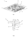
- the Fig. 1 shows a schematic perspective view of a cooktop or a hearth 1.
- the stove 1 is in particular a gas stove.
- the stove 1 comprises a cooking station 2, in particular a gas hob.
- the hotplate 2 has a trough-shaped base plate 3 in or on which a plurality of gas burners 4 are at least partially accommodated.
- the cooking station 2 comprises at least one gas burner 4.
- the cooking station 2 may include four gas burners. In the Fig. 1 only one of the gas burner 4 is provided with a reference numeral.
- the cooking station 2 also has a gas main 5.
- the gas main 5 is fluidly connected via a gas valve 6 and a supply line 7 with a gas burner 4.
- the Cooking zone 2 comprises at least one gas burner 4, the gas main 5, at least one gas valve 6 and at least one supply line 7.
- each gas burner 4, a gas valve 6 and a supply line 7 are assigned.
- the gas valve 6 is adapted to control a fuel gas flow from the gas main 5 through the supply line 7 to the gas burner 4 stepless or stepped.
- Each gas valve 6 has an operating shaft 8.
- the operating shaft 8 projects out of a valve housing of the gas valve 6. In particular, the operating shaft 8 protrudes beyond the trough-shaped bottom plate 3.
- the Fig. 2 1 shows a schematic sectional view of a domestic appliance operating arrangement 9.
- the domestic appliance operating arrangement 9 comprises the operating shaft 8, an actuating knob 10 arranged on or on the actuating shaft 8 and a fastening device 11 for fastening the actuating knob 10 to the actuating shaft 8.
- the Fig. 3 shows in a schematic sectional view of the operating shaft 8.
- the operating shaft 8 comprises an annular groove 12 into which the fastening device 11 engages for securing the actuating knob 10 to the actuating shaft 8 in a form-fitting manner.
- the Fig. 4 shows a schematic view of the fastening device 11.
- the fastening device 11 is in particular made of a spring steel wire.
- the fastening device 11 has in particular a U-shape.
- the fastening device 11 has at least two gripping arms 13, 14, which are adapted to partially surround the operating shaft 8. In particular, the at least two gripper arms 13, 14 are adapted to engage in the annular groove 12.
- the fastening device 11 is elastically deformable.
- Each gripping arm has a groove engagement section 15, 16.
- a receiving portion 17 for receiving the operating shaft 8 is provided on the operation knob 10.
- the receiving portion 17 is in particular tubular.
- the actuating shaft 8 comprises a lateral flattening 18, in which the receiving portion 17 engages positively.
- On the receiving portion 17 further lateral recesses 19 are provided through which the Nuteingriffsabête 15, 16 of the gripping arms 13, 14 of the fastening device 11 can engage in the annular groove 12 of the actuating shaft 8.
- the actuating knob 10 is pushed with the mounted fastening device 11 on the operating shaft 8.
- the operating shaft 8 in the Fig. 3 shown insertion bevel 20 for insertion thereof into the receiving portion 17 of the actuating knob 10.
- the height of an urging force F on for pressing the operating knob 10 and the fastening device 11 in an axial direction A of the operating shaft 8 on the same can be adjusted by a variation of a geometry of the insertion bevel 20 of the operating shaft 8.
- an inclination of the insertion bevel 20 for setting the pressing force F on can be varied.
- the Nuteingriffsabête 15, 16 are disengaged from the annular groove 12 and the actuating knob 10 can be deducted with the fastening device 11 in the axial direction A of the operating shaft 8 of this.
- the axial direction A of the actuating shaft is preferably oriented parallel to a central axis 22 of the actuating shaft 8.
- the pressing force F on when pressing the operating knob 10 and the fixing device 11 on the operating shaft 8 in the axial direction A thereof is smaller than a withdrawal force F Ab when removing the operating knob 10 and the fastening device 11 of the operating shaft 8 in the axial direction A thereof.
- the pressing force F on is smaller by a predetermined factor than the pull-off force F Ab .
- the predetermined factor is preferably 0.8, more preferably 0.7, further preferably 0.6, further preferably 0.5, and further preferably 0.4.
- the withdrawal force F Ab is greater than 50 N.
- the pressing force F on is preferably less than 30 N. This can damage the gas valve 6 when pressing the operating knob 10 and the fastening device 11 on the Operating shaft 8 can be prevented. Because the gripper arms 13, 14 engage positively in the annular groove 12, a very high pull-off force F Ab of more than 50 N can be achieved. As a result, the operating knob 10 and the fastening device 11 are not removable by a user from the gas valve 6 without additional tools. Furthermore, the low pressing force F on prevents damage to the gas valve 6 during assembly of the operating knob 10.
Landscapes
- Engineering & Computer Science (AREA)
- General Engineering & Computer Science (AREA)
- Mechanical Engineering (AREA)
- Chemical & Material Sciences (AREA)
- Combustion & Propulsion (AREA)
- Physics & Mathematics (AREA)
- General Physics & Mathematics (AREA)
- Automation & Control Theory (AREA)
- Feeding And Controlling Fuel (AREA)
- Mechanically-Actuated Valves (AREA)
- Cookers (AREA)
Applications Claiming Priority (1)
| Application Number | Priority Date | Filing Date | Title |
|---|---|---|---|
| ES201430805A ES2552602B1 (es) | 2014-05-28 | 2014-05-28 | Disposición de mando de aparato doméstico, válvula de gas, y cocina |
Publications (2)
| Publication Number | Publication Date |
|---|---|
| EP2952817A1 true EP2952817A1 (fr) | 2015-12-09 |
| EP2952817B1 EP2952817B1 (fr) | 2019-07-10 |
Family
ID=53188906
Family Applications (1)
| Application Number | Title | Priority Date | Filing Date |
|---|---|---|---|
| EP15167837.2A Active EP2952817B1 (fr) | 2014-05-28 | 2015-05-15 | Vanne de gaz avec un système de commande d'un appareil ménager et cuisinière |
Country Status (3)
| Country | Link |
|---|---|
| EP (1) | EP2952817B1 (fr) |
| ES (1) | ES2552602B1 (fr) |
| TR (1) | TR201911177T4 (fr) |
Cited By (2)
| Publication number | Priority date | Publication date | Assignee | Title |
|---|---|---|---|---|
| EP3266965A4 (fr) * | 2015-03-03 | 2018-10-31 | Alpha Corporation | Poignée de manipulation et structure de corps de poignée de poignée de manipulation |
| EP4015914A1 (fr) * | 2020-12-18 | 2022-06-22 | BSH Hausgeräte GmbH | Dispositif de cuisson doté d'un bouton de commande |
Citations (3)
| Publication number | Priority date | Publication date | Assignee | Title |
|---|---|---|---|---|
| US2172977A (en) * | 1937-10-12 | 1939-09-12 | Gen Electric | Push-on type handle |
| EP2527951A2 (fr) * | 2011-05-19 | 2012-11-28 | BSH Bosch und Siemens Hausgeräte GmbH | Élément de commande pour un appareil ménager ainsi qu'appareil ménager avec un dispositif de commande doté d'un élément de commande |
| EP2620831A2 (fr) * | 2011-10-26 | 2013-07-31 | BSH Bosch und Siemens Hausgeräte GmbH | Elément de commande pour une valve, valve, combinaison d'éléments de commande et valve ainsi qu'appareil ménager |
Family Cites Families (6)
| Publication number | Priority date | Publication date | Assignee | Title |
|---|---|---|---|---|
| US2256419A (en) * | 1940-01-08 | 1941-09-16 | Tinnerman Products Inc | Knob connection or the like |
| US2322949A (en) * | 1941-05-22 | 1943-06-29 | Lux Clock Mfg Company Inc | Spindle and knob construction |
| GB701014A (en) * | 1951-07-03 | 1953-12-16 | Simmonds Aerocessories Ltd | Improvements relating to knobs, handles and other parts having a hub for connection to a shaft, rod, spindle or the like |
| GB727402A (en) * | 1951-07-19 | 1955-03-30 | Cossor Ltd A C | Improvements in and relating to adjusting knobs for electric components |
| JPS55122521U (fr) * | 1979-02-22 | 1980-08-30 | ||
| ES2555203B1 (es) * | 2014-06-25 | 2016-10-04 | Bsh Electrodomésticos España, S.A. | Disposición de mando de aparato doméstico, válvula de gas, y cocina |
-
2014
- 2014-05-28 ES ES201430805A patent/ES2552602B1/es not_active Expired - Fee Related
-
2015
- 2015-05-15 TR TR2019/11177T patent/TR201911177T4/tr unknown
- 2015-05-15 EP EP15167837.2A patent/EP2952817B1/fr active Active
Patent Citations (3)
| Publication number | Priority date | Publication date | Assignee | Title |
|---|---|---|---|---|
| US2172977A (en) * | 1937-10-12 | 1939-09-12 | Gen Electric | Push-on type handle |
| EP2527951A2 (fr) * | 2011-05-19 | 2012-11-28 | BSH Bosch und Siemens Hausgeräte GmbH | Élément de commande pour un appareil ménager ainsi qu'appareil ménager avec un dispositif de commande doté d'un élément de commande |
| EP2620831A2 (fr) * | 2011-10-26 | 2013-07-31 | BSH Bosch und Siemens Hausgeräte GmbH | Elément de commande pour une valve, valve, combinaison d'éléments de commande et valve ainsi qu'appareil ménager |
Cited By (3)
| Publication number | Priority date | Publication date | Assignee | Title |
|---|---|---|---|---|
| EP3266965A4 (fr) * | 2015-03-03 | 2018-10-31 | Alpha Corporation | Poignée de manipulation et structure de corps de poignée de poignée de manipulation |
| US10697206B2 (en) | 2015-03-03 | 2020-06-30 | Alpha Corporation | Operation handle and handle main body structure for operation handle |
| EP4015914A1 (fr) * | 2020-12-18 | 2022-06-22 | BSH Hausgeräte GmbH | Dispositif de cuisson doté d'un bouton de commande |
Also Published As
| Publication number | Publication date |
|---|---|
| EP2952817B1 (fr) | 2019-07-10 |
| ES2552602A1 (es) | 2015-11-30 |
| ES2552602B1 (es) | 2016-09-14 |
| TR201911177T4 (tr) | 2019-08-21 |
Similar Documents
| Publication | Publication Date | Title |
|---|---|---|
| DE69705088T2 (de) | Gasgerät zum Erhitzen und/oder zum Kochen von Nahrungsmitteln und dergleichen | |
| EP3010382A1 (fr) | Grill et chambre à charbon de bois | |
| EP3278025A1 (fr) | Brûleur à gaz et plaque de cuisson à gaz | |
| EP1908333B1 (fr) | Procede de commande d un dispositif chauffant d'un appareil electrique chauffant a plusieurs dispositifs chauffants | |
| EP2952817B1 (fr) | Vanne de gaz avec un système de commande d'un appareil ménager et cuisinière | |
| EP2527951B1 (fr) | Élément de commande pour un appareil ménager ainsi qu'appareil ménager avec un dispositif de commande doté d'un élément de commande | |
| EP3598007A3 (fr) | Système de plaque de cuisson | |
| DE102010062578A1 (de) | Bedienvorrichtung für ein Haushaltsgerät sowie Kochfeld mit einer derartigen Bedienvorrichtung | |
| EP3032370B1 (fr) | Systeme d'utilisation d'un appareil menager, vanne de gaz et cuisiniere | |
| WO2016075579A1 (fr) | Dispositif de raccordement et table de cuisson à gaz | |
| EP3012536B1 (fr) | Plaque de cuisson a gaz | |
| EP3021190A2 (fr) | Plaque de cuisson au gaz et systeme de plaque de cuisson | |
| EP2600066A2 (fr) | Dispositif de commande pour un plan de cuisson, plan de cuisson doté d'un tel dispositif de commande et procédé de fonctionnement d'un plan de cuisson | |
| EP3096085A1 (fr) | Système d'utilisation d'un appareil ménager, vanne de gaz et poste de cuisson | |
| EP2857751A1 (fr) | Dispositif de fixation destiné à la fixation antigiratoire d'une conduite sur un boîtier d'un appareil ménager, agencement de fixation pour un appareil ménager et appareil ménager | |
| EP2341291B1 (fr) | Tôle de fixation pour la fixation d'une vanne de gaz sur une conduite de gaz | |
| EP3018409B1 (fr) | Plaque de cuisson avec une partie inférieure de brûleur à gaz | |
| EP3161386B1 (fr) | Foyer de cuisson au gaz | |
| EP2960581B1 (fr) | Plaque de cuisson | |
| EP3084311B1 (fr) | Plaque de cuisson | |
| EP3023699B1 (fr) | Plaque de cuisson au gaz | |
| DE102014100414A1 (de) | Dunstabzugshaubeneinrichtung | |
| EP2860455A1 (fr) | Dispositif de positionnement d'un brûleur à gaz dans ou sur une plaque de cuisson, plaque de cuisson et brûleur à gaz | |
| EP3102888B1 (fr) | Brûleur à gaz, arrangement de brûleurs à gaz, poste de cuisson, et cuisinière | |
| EP3215793A1 (fr) | Table de cuisson à gaz |
Legal Events
| Date | Code | Title | Description |
|---|---|---|---|
| PUAI | Public reference made under article 153(3) epc to a published international application that has entered the european phase |
Free format text: ORIGINAL CODE: 0009012 |
|
| AK | Designated contracting states |
Kind code of ref document: A1 Designated state(s): AL AT BE BG CH CY CZ DE DK EE ES FI FR GB GR HR HU IE IS IT LI LT LU LV MC MK MT NL NO PL PT RO RS SE SI SK SM TR |
|
| AX | Request for extension of the european patent |
Extension state: BA ME |
|
| 17P | Request for examination filed |
Effective date: 20160609 |
|
| RBV | Designated contracting states (corrected) |
Designated state(s): AL AT BE BG CH CY CZ DE DK EE ES FI FR GB GR HR HU IE IS IT LI LT LU LV MC MK MT NL NO PL PT RO RS SE SI SK SM TR |
|
| STAA | Information on the status of an ep patent application or granted ep patent |
Free format text: STATUS: EXAMINATION IS IN PROGRESS |
|
| 17Q | First examination report despatched |
Effective date: 20161123 |
|
| RIC1 | Information provided on ipc code assigned before grant |
Ipc: G05G 1/12 20060101ALI20181122BHEP Ipc: F24C 3/12 20060101AFI20181122BHEP Ipc: F16B 21/18 20060101ALI20181122BHEP Ipc: F16B 2/24 20060101ALI20181122BHEP |
|
| GRAP | Despatch of communication of intention to grant a patent |
Free format text: ORIGINAL CODE: EPIDOSNIGR1 |
|
| STAA | Information on the status of an ep patent application or granted ep patent |
Free format text: STATUS: GRANT OF PATENT IS INTENDED |
|
| INTG | Intention to grant announced |
Effective date: 20190102 |
|
| GRAS | Grant fee paid |
Free format text: ORIGINAL CODE: EPIDOSNIGR3 |
|
| GRAA | (expected) grant |
Free format text: ORIGINAL CODE: 0009210 |
|
| STAA | Information on the status of an ep patent application or granted ep patent |
Free format text: STATUS: THE PATENT HAS BEEN GRANTED |
|
| AK | Designated contracting states |
Kind code of ref document: B1 Designated state(s): AL AT BE BG CH CY CZ DE DK EE ES FI FR GB GR HR HU IE IS IT LI LT LU LV MC MK MT NL NO PL PT RO RS SE SI SK SM TR |
|
| REG | Reference to a national code |
Ref country code: GB Ref legal event code: FG4D Free format text: NOT ENGLISH |
|
| REG | Reference to a national code |
Ref country code: CH Ref legal event code: EP Ref country code: AT Ref legal event code: REF Ref document number: 1153994 Country of ref document: AT Kind code of ref document: T Effective date: 20190715 |
|
| REG | Reference to a national code |
Ref country code: DE Ref legal event code: R096 Ref document number: 502015009568 Country of ref document: DE |
|
| REG | Reference to a national code |
Ref country code: IE Ref legal event code: FG4D Free format text: LANGUAGE OF EP DOCUMENT: GERMAN |
|
| REG | Reference to a national code |
Ref country code: NL Ref legal event code: MP Effective date: 20190710 |
|
| REG | Reference to a national code |
Ref country code: LT Ref legal event code: MG4D |
|
| PG25 | Lapsed in a contracting state [announced via postgrant information from national office to epo] |
Ref country code: BG Free format text: LAPSE BECAUSE OF FAILURE TO SUBMIT A TRANSLATION OF THE DESCRIPTION OR TO PAY THE FEE WITHIN THE PRESCRIBED TIME-LIMIT Effective date: 20191010 Ref country code: SE Free format text: LAPSE BECAUSE OF FAILURE TO SUBMIT A TRANSLATION OF THE DESCRIPTION OR TO PAY THE FEE WITHIN THE PRESCRIBED TIME-LIMIT Effective date: 20190710 Ref country code: NL Free format text: LAPSE BECAUSE OF FAILURE TO SUBMIT A TRANSLATION OF THE DESCRIPTION OR TO PAY THE FEE WITHIN THE PRESCRIBED TIME-LIMIT Effective date: 20190710 Ref country code: PT Free format text: LAPSE BECAUSE OF FAILURE TO SUBMIT A TRANSLATION OF THE DESCRIPTION OR TO PAY THE FEE WITHIN THE PRESCRIBED TIME-LIMIT Effective date: 20191111 Ref country code: LT Free format text: LAPSE BECAUSE OF FAILURE TO SUBMIT A TRANSLATION OF THE DESCRIPTION OR TO PAY THE FEE WITHIN THE PRESCRIBED TIME-LIMIT Effective date: 20190710 Ref country code: HR Free format text: LAPSE BECAUSE OF FAILURE TO SUBMIT A TRANSLATION OF THE DESCRIPTION OR TO PAY THE FEE WITHIN THE PRESCRIBED TIME-LIMIT Effective date: 20190710 Ref country code: FI Free format text: LAPSE BECAUSE OF FAILURE TO SUBMIT A TRANSLATION OF THE DESCRIPTION OR TO PAY THE FEE WITHIN THE PRESCRIBED TIME-LIMIT Effective date: 20190710 Ref country code: NO Free format text: LAPSE BECAUSE OF FAILURE TO SUBMIT A TRANSLATION OF THE DESCRIPTION OR TO PAY THE FEE WITHIN THE PRESCRIBED TIME-LIMIT Effective date: 20191010 |
|
| PG25 | Lapsed in a contracting state [announced via postgrant information from national office to epo] |
Ref country code: LV Free format text: LAPSE BECAUSE OF FAILURE TO SUBMIT A TRANSLATION OF THE DESCRIPTION OR TO PAY THE FEE WITHIN THE PRESCRIBED TIME-LIMIT Effective date: 20190710 Ref country code: GR Free format text: LAPSE BECAUSE OF FAILURE TO SUBMIT A TRANSLATION OF THE DESCRIPTION OR TO PAY THE FEE WITHIN THE PRESCRIBED TIME-LIMIT Effective date: 20191011 Ref country code: ES Free format text: LAPSE BECAUSE OF FAILURE TO SUBMIT A TRANSLATION OF THE DESCRIPTION OR TO PAY THE FEE WITHIN THE PRESCRIBED TIME-LIMIT Effective date: 20190710 Ref country code: IS Free format text: LAPSE BECAUSE OF FAILURE TO SUBMIT A TRANSLATION OF THE DESCRIPTION OR TO PAY THE FEE WITHIN THE PRESCRIBED TIME-LIMIT Effective date: 20191110 Ref country code: RS Free format text: LAPSE BECAUSE OF FAILURE TO SUBMIT A TRANSLATION OF THE DESCRIPTION OR TO PAY THE FEE WITHIN THE PRESCRIBED TIME-LIMIT Effective date: 20190710 Ref country code: AL Free format text: LAPSE BECAUSE OF FAILURE TO SUBMIT A TRANSLATION OF THE DESCRIPTION OR TO PAY THE FEE WITHIN THE PRESCRIBED TIME-LIMIT Effective date: 20190710 |
|
| PG25 | Lapsed in a contracting state [announced via postgrant information from national office to epo] |
Ref country code: DK Free format text: LAPSE BECAUSE OF FAILURE TO SUBMIT A TRANSLATION OF THE DESCRIPTION OR TO PAY THE FEE WITHIN THE PRESCRIBED TIME-LIMIT Effective date: 20190710 Ref country code: RO Free format text: LAPSE BECAUSE OF FAILURE TO SUBMIT A TRANSLATION OF THE DESCRIPTION OR TO PAY THE FEE WITHIN THE PRESCRIBED TIME-LIMIT Effective date: 20190710 Ref country code: EE Free format text: LAPSE BECAUSE OF FAILURE TO SUBMIT A TRANSLATION OF THE DESCRIPTION OR TO PAY THE FEE WITHIN THE PRESCRIBED TIME-LIMIT Effective date: 20190710 Ref country code: PL Free format text: LAPSE BECAUSE OF FAILURE TO SUBMIT A TRANSLATION OF THE DESCRIPTION OR TO PAY THE FEE WITHIN THE PRESCRIBED TIME-LIMIT Effective date: 20190710 |
|
| PG25 | Lapsed in a contracting state [announced via postgrant information from national office to epo] |
Ref country code: IS Free format text: LAPSE BECAUSE OF FAILURE TO SUBMIT A TRANSLATION OF THE DESCRIPTION OR TO PAY THE FEE WITHIN THE PRESCRIBED TIME-LIMIT Effective date: 20200224 Ref country code: SK Free format text: LAPSE BECAUSE OF FAILURE TO SUBMIT A TRANSLATION OF THE DESCRIPTION OR TO PAY THE FEE WITHIN THE PRESCRIBED TIME-LIMIT Effective date: 20190710 Ref country code: SM Free format text: LAPSE BECAUSE OF FAILURE TO SUBMIT A TRANSLATION OF THE DESCRIPTION OR TO PAY THE FEE WITHIN THE PRESCRIBED TIME-LIMIT Effective date: 20190710 Ref country code: CZ Free format text: LAPSE BECAUSE OF FAILURE TO SUBMIT A TRANSLATION OF THE DESCRIPTION OR TO PAY THE FEE WITHIN THE PRESCRIBED TIME-LIMIT Effective date: 20190710 |
|
| REG | Reference to a national code |
Ref country code: DE Ref legal event code: R097 Ref document number: 502015009568 Country of ref document: DE |
|
| PLBE | No opposition filed within time limit |
Free format text: ORIGINAL CODE: 0009261 |
|
| STAA | Information on the status of an ep patent application or granted ep patent |
Free format text: STATUS: NO OPPOSITION FILED WITHIN TIME LIMIT |
|
| PG2D | Information on lapse in contracting state deleted |
Ref country code: IS |
|
| 26N | No opposition filed |
Effective date: 20200603 |
|
| PG25 | Lapsed in a contracting state [announced via postgrant information from national office to epo] |
Ref country code: SI Free format text: LAPSE BECAUSE OF FAILURE TO SUBMIT A TRANSLATION OF THE DESCRIPTION OR TO PAY THE FEE WITHIN THE PRESCRIBED TIME-LIMIT Effective date: 20190710 |
|
| PG25 | Lapsed in a contracting state [announced via postgrant information from national office to epo] |
Ref country code: CH Free format text: LAPSE BECAUSE OF NON-PAYMENT OF DUE FEES Effective date: 20200531 Ref country code: MC Free format text: LAPSE BECAUSE OF FAILURE TO SUBMIT A TRANSLATION OF THE DESCRIPTION OR TO PAY THE FEE WITHIN THE PRESCRIBED TIME-LIMIT Effective date: 20190710 Ref country code: LI Free format text: LAPSE BECAUSE OF NON-PAYMENT OF DUE FEES Effective date: 20200531 |
|
| REG | Reference to a national code |
Ref country code: BE Ref legal event code: MM Effective date: 20200531 |
|
| PG25 | Lapsed in a contracting state [announced via postgrant information from national office to epo] |
Ref country code: LU Free format text: LAPSE BECAUSE OF NON-PAYMENT OF DUE FEES Effective date: 20200515 |
|
| PG25 | Lapsed in a contracting state [announced via postgrant information from national office to epo] |
Ref country code: IE Free format text: LAPSE BECAUSE OF NON-PAYMENT OF DUE FEES Effective date: 20200515 Ref country code: FR Free format text: LAPSE BECAUSE OF NON-PAYMENT OF DUE FEES Effective date: 20200531 |
|
| PG25 | Lapsed in a contracting state [announced via postgrant information from national office to epo] |
Ref country code: BE Free format text: LAPSE BECAUSE OF NON-PAYMENT OF DUE FEES Effective date: 20200531 |
|
| REG | Reference to a national code |
Ref country code: AT Ref legal event code: MM01 Ref document number: 1153994 Country of ref document: AT Kind code of ref document: T Effective date: 20200515 |
|
| PGFP | Annual fee paid to national office [announced via postgrant information from national office to epo] |
Ref country code: IT Payment date: 20210531 Year of fee payment: 7 Ref country code: DE Payment date: 20210531 Year of fee payment: 7 |
|
| PG25 | Lapsed in a contracting state [announced via postgrant information from national office to epo] |
Ref country code: AT Free format text: LAPSE BECAUSE OF NON-PAYMENT OF DUE FEES Effective date: 20200515 |
|
| PGFP | Annual fee paid to national office [announced via postgrant information from national office to epo] |
Ref country code: TR Payment date: 20210506 Year of fee payment: 7 Ref country code: GB Payment date: 20210525 Year of fee payment: 7 |
|
| PG25 | Lapsed in a contracting state [announced via postgrant information from national office to epo] |
Ref country code: MT Free format text: LAPSE BECAUSE OF FAILURE TO SUBMIT A TRANSLATION OF THE DESCRIPTION OR TO PAY THE FEE WITHIN THE PRESCRIBED TIME-LIMIT Effective date: 20190710 Ref country code: CY Free format text: LAPSE BECAUSE OF FAILURE TO SUBMIT A TRANSLATION OF THE DESCRIPTION OR TO PAY THE FEE WITHIN THE PRESCRIBED TIME-LIMIT Effective date: 20190710 |
|
| PG25 | Lapsed in a contracting state [announced via postgrant information from national office to epo] |
Ref country code: MK Free format text: LAPSE BECAUSE OF FAILURE TO SUBMIT A TRANSLATION OF THE DESCRIPTION OR TO PAY THE FEE WITHIN THE PRESCRIBED TIME-LIMIT Effective date: 20190710 |
|
| REG | Reference to a national code |
Ref country code: DE Ref legal event code: R119 Ref document number: 502015009568 Country of ref document: DE |
|
| GBPC | Gb: european patent ceased through non-payment of renewal fee |
Effective date: 20220515 |
|
| PG25 | Lapsed in a contracting state [announced via postgrant information from national office to epo] |
Ref country code: GB Free format text: LAPSE BECAUSE OF NON-PAYMENT OF DUE FEES Effective date: 20220515 Ref country code: DE Free format text: LAPSE BECAUSE OF NON-PAYMENT OF DUE FEES Effective date: 20221201 |
|
| PG25 | Lapsed in a contracting state [announced via postgrant information from national office to epo] |
Ref country code: IT Free format text: LAPSE BECAUSE OF NON-PAYMENT OF DUE FEES Effective date: 20220515 |
|
| PG25 | Lapsed in a contracting state [announced via postgrant information from national office to epo] |
Ref country code: TR Free format text: LAPSE BECAUSE OF NON-PAYMENT OF DUE FEES Effective date: 20220515 |