EP2953216B1 - Funkenstrecke mit kühl- und/oder dämpfungseinrichtung - Google Patents
Funkenstrecke mit kühl- und/oder dämpfungseinrichtung Download PDFInfo
- Publication number
- EP2953216B1 EP2953216B1 EP15170367.5A EP15170367A EP2953216B1 EP 2953216 B1 EP2953216 B1 EP 2953216B1 EP 15170367 A EP15170367 A EP 15170367A EP 2953216 B1 EP2953216 B1 EP 2953216B1
- Authority
- EP
- European Patent Office
- Prior art keywords
- spark gap
- electrode
- discs
- auxiliary ignition
- spark
- Prior art date
- Legal status (The legal status is an assumption and is not a legal conclusion. Google has not performed a legal analysis and makes no representation as to the accuracy of the status listed.)
- Active
Links
Images


Classifications
-
- H—ELECTRICITY
- H01—ELECTRIC ELEMENTS
- H01T—SPARK GAPS; OVERVOLTAGE ARRESTERS USING SPARK GAPS; SPARKING PLUGS; CORONA DEVICES; GENERATING IONS TO BE INTRODUCED INTO NON-ENCLOSED GASES
- H01T2/00—Spark gaps comprising auxiliary triggering means
- H01T2/02—Spark gaps comprising auxiliary triggering means comprising a trigger electrode or an auxiliary spark gap
-
- H—ELECTRICITY
- H01—ELECTRIC ELEMENTS
- H01T—SPARK GAPS; OVERVOLTAGE ARRESTERS USING SPARK GAPS; SPARKING PLUGS; CORONA DEVICES; GENERATING IONS TO BE INTRODUCED INTO NON-ENCLOSED GASES
- H01T1/00—Details of spark gaps
- H01T1/02—Means for extinguishing arc
-
- H—ELECTRICITY
- H01—ELECTRIC ELEMENTS
- H01T—SPARK GAPS; OVERVOLTAGE ARRESTERS USING SPARK GAPS; SPARKING PLUGS; CORONA DEVICES; GENERATING IONS TO BE INTRODUCED INTO NON-ENCLOSED GASES
- H01T1/00—Details of spark gaps
- H01T1/02—Means for extinguishing arc
- H01T1/08—Means for extinguishing arc using flow of arc-extinguishing fluid
- H01T1/10—Means for extinguishing arc using flow of arc-extinguishing fluid with extinguishing fluid evolved from solid material by heat of arc
-
- H—ELECTRICITY
- H01—ELECTRIC ELEMENTS
- H01T—SPARK GAPS; OVERVOLTAGE ARRESTERS USING SPARK GAPS; SPARKING PLUGS; CORONA DEVICES; GENERATING IONS TO BE INTRODUCED INTO NON-ENCLOSED GASES
- H01T1/00—Details of spark gaps
- H01T1/15—Details of spark gaps for protection against excessive pressure
-
- H—ELECTRICITY
- H01—ELECTRIC ELEMENTS
- H01T—SPARK GAPS; OVERVOLTAGE ARRESTERS USING SPARK GAPS; SPARKING PLUGS; CORONA DEVICES; GENERATING IONS TO BE INTRODUCED INTO NON-ENCLOSED GASES
- H01T4/00—Overvoltage arresters using spark gaps
- H01T4/16—Overvoltage arresters using spark gaps having a plurality of gaps arranged in series
Definitions
- the invention relates to a spark gap with cooling and / or damping device.
- spark gaps Numerous arrangements for spark gaps are known in the prior art. It should be noted that spark gaps are not trivial arrangements, but for a reliable ignition and for the cooling of the resulting plasma arc a not to be underestimated effort must be driven. Previous spark gaps were characterized by a specific to be taken pulse energy.
- EP 1 542 323 A2 shows a spark gap with a starting aid with a voltage-switching element.
- FIGS. 1 and 2 show a first arrangement according to embodiments of the invention in two different states.
- the spark gap 1 an adaptive cooling and / or damping device, which will be explained in more detail below.
- the spark gap 1 has at least a first spark gap electrode FS 1 and a second spark gap electrode FS 2.
- the spark gap can also have further electrodes for different purposes.
- measuring electrodes may be provided to measure, for example, the degradation of insulating components within the spark gap in a capacitive, inductive or resistive manner.
- the spark gap 1 has at least one auxiliary ignition electrode ZE for connection to an ignition circuit.
- auxiliary ignition electrode ZE is spatially adjacent to the first spark gap electrode FS 1 and spaced from the second spark gap electrode FS 2 .
- Ignition auxiliary electrode ZE based on the direction of the first spark gap electrode FS 1 and second spark gap electrode FS 2 arranged laterally to this direction.
- a low-conductivity material BRZ is introduced for ignition assistance. That is, in the event of an overvoltage, ionization will first take place via the auxiliary starting electrode and the first spark gap electrode FS 1 , and then the main spark gap between the first spark gap electrode FS 1 and the second spark gap electrode FS 2 will be ignited.
- a plurality of slices S 1 , S 2 ,... S n are now introduced between the auxiliary starting electrode ZE and the second spark gap electrode FS 2 .
- These plurality of disks S 1 , S 2 ,... S n are electrically insulated from the auxiliary starting electrode ZE and the first spark gap electrode FS 1 by means of an electrical insulator ISO 1 .
- the slices S 1 , S 2 , ... S n each have an opening, wherein the openings of the slices S 1 , S 2 , ... S n are arranged so that they form an arc channel between the second spark gap electrode FS second and the first spark gap electrode FS 1 .
- These plurality of disks S 1 , S 2 , ... S n serve as cooling and / or damping device.
- FIG. 1 In the case of FIG. 1 is the spark gap in the off state, ie the spark gap 1 does not conduct electricity. If there is now a current flow, ie the spark gap ignites, then an arc plasma is formed.
- the spark gap 1 can now adjust to the event.
- the arc plasma will build up a correspondingly higher heat and pressure, so that now through the pressure effect the disks in the lateral direction as in FIG. 2 shown can be pushed apart. This extends on the one hand the spark gap channel, because at the same time.
- the arc plasma and the resulting heat to the environment can be derived according to the arrows in the interstices of the discs. Since now at least a portion of the ionized gas is removed from the spark gap channel, the conductivity of the arc plasma decreases. Since energy is needed to move the disks and at least a portion of the pressure escapes when the disks are pushed apart, the pressure increase is damped.
- the spark gap electrodes may be made of WCu or other preferably arc-resistant materials.
- discs S 1 , S 2 , ... S n are made of a suitable material.
- the slices S 1 , S 2 ,... S n from a hard-gasifying material such as polyoxymethylene (POM) or from polyetheretherketone (PEEK), the slices S 1 , S 2 , n preferably made of an arc-resistant material such as WCu (tungsten-copper), so that usually a variety of pulse events can be derived.
- a hard-gasifying material such as polyoxymethylene (POM) or from polyetheretherketone (PEEK)
- PEEK polyetheretherketone
- At least part of the plurality of slices S 1 , S 2 ,... S n may comprise an electrically conductive material.
- the heat capacity for the Selection should be a criterion.
- the disks may comprise copper or tungsten or compounds thereof.
- At least a portion of the plurality of slices S 1 , S 2 ,... S n may comprise an electrically nonconductive material.
- heat capacity for the selection can be a criterion.
- the discs may have ceramic.
- the plurality of electrically conductive panes S 1 , S 2 ,... S n can have a more or less temperature-resistant material.
- At least a portion of the plurality of slices S 1, S 2, ... S n grooves or electrically conductive / non-conductive spacers have R as shown in FIG. 4 shown.
- one or more of the (electrically conductive or electrically insulating) disks S 1 , S 2 ,... S n have a porous material.
- a porous or sintered material may be used.
- An essential aspect of a porous material is that this material forms channels, so that a plasma of the spark gap can be derived attenuated.
- porous material may include (sintered) sand (resulting in a solid shape), and / or spheres made of, for example, steel, POM, ceramic and / or flux or fibers, for example of ceramic material.
- Both the grooves and the spacers as well as the grooves R allow plasma to escape directly at the beginning of an impulse event. If a stronger pulse event occurs, then the slices S 1 , S 2 ,... S n can be pushed apart in order to further assist the outflow under the influence of the further increasing pressure. However, this is not absolutely necessary.
- the spacers or grooves R in the individual panes can be introduced into the surface, for example, by stamping, pressing or embossing. If several discs are stacked, depending on the position of the spacers or grooves to each other a free volume between the discs are generated. The plasma has the possibility to flow outward through this free volume. The same applies to spacers which can be applied to the surface of the slices S 1 , S 2 ,... S n alternatively or additionally.
- a hard gas insulating material is not mandatory for insulation ISO 1 adjacent to the first spark gap electrode FS 1 , it is advantageous for effective cooling of the arc plasma because hard gas materials have the property of narrowing the arc channel.
- the low-conductive material BRZ and / or the auxiliary ignition electrode ZE may have an annular opening, wherein the openings of the slices S 1 , S 2 , ... S n are arranged so that they form an arc channel between the second spark gap electrode FS 2 and the form the first spark gap electrode FS 1 .
- the spark gap channel can now also be designed in the connecting direction from the first spark gap electrode to the second spark gap electrode.
- a cylindrical channel for example, a slightly eccentric opening arranged as in Fig. 3
- On the right side shown in the discs cause that at a certain angular displacement of the discs to each other results in a helical path.
- a slot-like opening as in FIG. 3 can be reached on the left side.
- the openings can in principle take all possible forms. It is also possible to use a part of the disks in one mold and another part in another mold.
- the individual elements are held only by their own weight, in which case it is expedient to provide guide devices so that the individual elements return to their previous position after being pushed apart.
- the adaptive property can only be used once, e.g. in that the elements are suitably pressure-releasably connected.
- the elements are suitably pressure-releasably connected.
- a suitable adhesive or a solder e.g.
- the spark gap 1 has an elastic element D, so that the spark gap electrodes FS 1 , FS 2 and the slices S 1 , S 2 , ... S n are held.
- an elastic element D may be a pressurization by means of a spring or a circumferential elastic element, for example, of an elastomer similar to a rubber band or the like.
- the spark gap 1 may also have a encompassing housing G.
- the housing G can also combine the function of the elastic element.
- an outflow is now either possible only in the intermediate regions of the disks or, as far as the housing G has openings, plasma can continue to escape into the environment.
- arc diaphragm ISO 2 In order to direct the arc plasma targeted can also be provided that between the slices S 1 , S 2 , ... S n and the auxiliary ignition electrode ZE an arc diaphragm ISO 2 is attached.
- the spark gap has an elastic element D, so that the spark gap electrodes FS 1 , FS 2 and the disks S 1 , S 2 , ... S n (pressure-displaceable) are held and that the electrically conductive disks S 1 , S 2 , ... S n can be displaced in the direction of the first spark gap electrode and the second spark gap electrode.
- the spark gap according to the invention can also be used in a spark gap arrangement with an ignition circuit, the ignition circuit connecting the second spark gap electrode FS 2 and the auxiliary ignition electrode ZE via a voltage-switching and / or voltage-limiting element.
- the ignition circuit connecting the second spark gap electrode FS 2 and the auxiliary ignition electrode ZE via a voltage-switching and / or voltage-limiting element.
- this can be done as in FIG. 1 and 2 a varistor and a gas discharge tube may be provided.
- the second spark gap electrode FS 2 is contacted with the auxiliary ignition electrode ZE by a voltage-switching element and / or a voltage-limiting element (for example a varistor), whereby a continuous current flow through the ignition circuit can be prevented.
- a voltage-switching element and / or a voltage-limiting element for example a varistor
- the upper potential is conducted to the auxiliary starting electrode ZE via the voltage-switching and / or the voltage-limiting element.
- the low-conductivity material BRZ At least part of the surface burns to the first spark gap electrode FS 1 and ionizes the combustion channel.
- the plasma creates a main discharge between the two spark gap electrodes.
- Insulation material ISO 1 or ISO 2 gasifies and cools the arc.
- the temperature and the pressure increase. From a certain threshold value of the pressure, the disks S 1 , S 2 , ... S n are pressed apart and thus form several large blow-off volumes, through which the ionized gas can escape.
- the plasma can be strongly cooled by the large surfaces between the discs.
- the structure thus forms a self-regulating system, since the pressure build-up and the pressure reduction depend on each other and simultaneously counteract each other.
- the distance between the discs is dimensioned so that the flow of the plasma is inhibited so much that outside the arrangement no or only very small amounts of ionized gas escape.
- the spacing of the cooling surfaces can be achieved by insulating or non-insulating and resistive, as well as a combination of insulating as non-insulating and resistive spacers.
- the invention makes it possible to adjust the outflow area adaptively to different requirements by means of different pulse energies.
- the arrangement according to the invention is simple to realize mechanically.
- the invention allows to provide a high discharge capacity by a large thermal mass.
- the high thermal mass also has a large surface, resulting in a high energy absorption.
- the plasma channel can be deionized and thus the conductivity of the plasma can be reduced.
- Other cooling mechanisms can be used to achieve efficient cooling and removal of the plasma.
- FIG. 5 is another illustrative embodiment, which is not part of the invention shown. This differs initially only in the shape of the disc S. 1
- the disc of FIG. 5 and FIG. 6 is not a disk of solid material but rather resembles (in plan view) a snail.
- Suitable screws - indicated in FIG. 6 - Can be made of sheet-metal material wound (particularly simple and inexpensive production) or milled from solid material or produced as such, for example by casting-like process.
- the properties of the winding ie the number of windings and the geometry of the channel created thereby, the properties such as flow behavior and cooling behavior can be specifically influenced.
- the material may be insulating or electrically conductive.
- a channel through the plasma of an arc can escape steamed. If the screw is constructed of a suitable material, then this can be used in addition to the cooling. In this case, the channel may be both uniform and irregular, such as in FIG. 6 indicated.
- the walls of the screw S 1 can run parallel to each other over the entire length, converge toward one another or diverge.
- the material in a worm shape S 1 may consist of one or more layers and different materials.
- material in a worm shape S 1 may comprise a conductive material such as copper or non-conductive material such as ceramic (as a flux or as a solid material).
- a layer structure may be comprised of one or more layers of ceramic and / or metal adjacent to an outgassing material, such as e.g. Polyoxymethylene (POM) be constructed.
- an outgassing material such as e.g. Polyoxymethylene (POM) be constructed.
- openings may also be provided in the other layers, which are either given by the material property itself and / or are particularly provided. Is e.g. the outgassing material is arranged in a (coarse) porous ceramic or in a wire-like grid is given a good access to the outgassing material with simultaneous stability.
- the number of openings can be distributed differently, so that, for example, in order to realize a smaller material removal in the multilayer material in a screw shape S 1 , the openings can be selectively attached, for example to minimize outgassing close to the spark gap.
- the number of holes (voids) increases with respect to the length of the channel.
- the (electrically conductive) material in a screw shape S 1 forms an opening, wherein the openings are arranged so that it forms an arc channel between the second spark gap electrode FS 2 and the first spark gap electrode FS 1 .
- the (electrically conductive) material S 1 can also be embodied as part of the second spark gap electrode FS 2 .
- the material S 1 is usually made in one piece and electrically conductive with the spark gap electrode FS 2 .
- the (electrically conductive) material S 1 is a separate component, then it may, if necessary, also be configured in such a way that, under the pressure of a plasma, an expansion of the channel formed can also take place. Ie similar to the Embodiment before, the spiral configuration can change their properties depending on the pressure.
- the housing G may have areas in which plasma could also escape to the outside. These areas are shown, for example, as a dotted housing G.
- FIG. 5 only a single disc S 1 is shown, it is obvious to the person skilled in the art that a plurality of discs can also be mounted one above the other in a corresponding arrangement. In this case, mixed forms can also be used. For example, individual discs can be used accordingly FIG. 6 be executed while other discs according to Figures 3 or 4 are executed.
- FIG. 5 may be provided that in the material in a worm shape S 1 further openings ⁇ 1 are provided so that plasma of the ignited spark gap can enter at more than one point in the channel.
- the second spark gap electrode FS 2 has at least one further opening ⁇ 1 , so that plasma can enter laterally into the channel formed by the material in a screw shape S 1 .
- FIG. 8 A possible sectional view through the second spark gap electrode FS and the material in a screw shape S 1 is shown in FIG FIG. 8 shown.
- the present invention provides a large thermal mass and surface in which the plasma has the opportunity to cool.
- the spiral shape and the imperfections to the partition wall dampening the plasma flow, resulting in a reduction of the thermal energy.
- a back pressure is generated, so that during the high-current phase, the conductivity in the combustion chamber is increased and the energy conversion in the spark gap decreases.
- the back pressure and the conductivity in the spark gap decrease.
- a higher arc burn voltage is produced, resulting in improved line follow current extinguishing capability.
- the material described above in a worm shape S 1 may comprise a conductive material and / or a non-conductive material.
- an inner wall W I and an outer wall W A can be made of a rather massive material with holes or a net-like material, which together include a porous material W Z located therebetween.
- porous material may include (sintered) sand (resulting in a solid shape), and / or spheres made of, for example, steel, POM, ceramic and / or flux or fibers, for example of ceramic material.
- low-conductivity material BRZ it may be any suitable material.
- the low conductivity material BRZ may be made of, for example, FR4, a material used for printed circuit boards consisting of an epoxy resin-filled glass fiber fabric, with a suitable surface coating such as graphite.
- any material made of plastic or ceramic is suitable, which has a certain conductivity, be it that the respective material corresponding conductive materials such as electrically conductive ceramics or graphite (embedded) or coated with these is.
Landscapes
- Plasma Technology (AREA)
Description
- Die Erfindung betrifft eine Funkenstrecke mit Kühl- und/oder Dämpfungseinrichtung.
- Aus dem Stand der Technik sind zahlreiche Anordnungen für Funkenstrecken bekannt. Dabei ist festzustellen, dass Funkenstrecken keine triviale Anordnungen sind, sondern für eine zuverlässige Zündung als auch für die Kühlung des entstanden Plasmalichtbogens ein nicht zu unterschätzender Aufwand getrieben werden muss. Bisherige Funkenstrecken zeichneten sich durch eine auf bestimmte zu übernehmende Impulsenergie aus.
- Allerdings stellt sich dies als nachteilig heraus da nunmehr eine optimierte Lösung für eine bestimmte Impulsenergie vorhanden ist, jedoch die Eingeschalten bei anderen Impulsenergien sub-optimal sind.
- Beispielsweise ist aus dem gattungsbildenden Stand der Technik die europäische Patentanmeldung
EP 1 542 323 A2 bekannt. Diese zeigt eine Funkenstrecke mit einer Zündhilfe mit einem spannungsschaltenden Element aufweist. - Zwar könnte man nun versuchen verschiedene Ableitorgane parallel zu betreiben, dabei ergeben sich jedoch Probleme in Bezug auf ein abgestimmtes Schaltverhalten. Zudem sind solche parallelen Anordnungen auch erheblich kostenintensiver.
- Es wäre daher wünschenswert eine flexiblere kostengünstige Lösung bereitstellen zu können.
- Die Lösung der Aufgabe erfolgt erfindungsgemäß durch die Merkmale des unabhängigen Anspruchs 1. Vorteilhafte Ausgestaltungen der Erfindung sind in den Unteransprüchen angegeben.
- Nachfolgend wird die Erfindung unter Bezugnahme auf die anliegende Zeichnung anhand bevorzugter Ausführungsformen näher erläutert.
- Es zeigen
- Fig. 1
- eine erste Anordnung gemäß Ausführungsformen der Erfindung in einem ersten Zustand,
- Fig. 2
- die erste Anordnung gemäß Ausführungsformen der Erfindung in einem zweiten Zustand,
- Fig. 3
- beispielhafte Ausführungen von Scheiben gemäß Ausführungsformen der Erfindung,
- Fig. 4
- eine weitere beispielhafte Ausführungsform von Scheiben in Draufsicht und Schnittdarstellungen,
- Fig. 5
- ein weiteres illustratives Ausführungsbeispiel nicht Teil der Erfindung
- Fig. 6
- einen Aspekt des weiteren illustrativen Ausführungsbeispiels
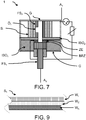
- Fig. 7
- Noch ein weiteres illustratives Ausführungsbeispiel nicht Teil der Erfindung
- Fig. 8
- einen Aspekt des noch weiteren illustrativen Ausführungsbeispiels und
- Fig. 9
- noch einen Aspekt des noch weiteren illustrativen Ausführungsbeispiels.
- Die
Figuren 1 und2 zeigen eine erste Anordnung gemäß Ausführungsformen der Erfindung in zwei unterschiedlichen Zuständen. - Dabei weist die Funkenstrecke 1 eine adaptive Kühl- und/oder Dämpfungseinrichtung auf, die nachfolgend näher erläutert werden wird.
- Die Funkenstrecke 1 weist zumindest eine erste Funkenstreckenelektrode FS1 und eine zweite Funkenstreckenelektrode FS2. Ohne weiteres kann die Funkenstrecke auch weitere Elektroden für unterschiedliche Zwecke aufweisen. Beispielsweise können Messelektroden vorgesehen sein, um z.B. die Degradierung von isolierenden Bauteilen innerhalb der Funkenstrecke auf kapazitivem, induktivem oder resistivem Wege zu messen.
- Weiterhin weist die Funkenstrecke 1 zumindest eine Zündhilfselektrode ZE zur Verbindung mit einem Zündkreis auf. Solche Anordnungen sind beispielsweise aus der
EP 1423894 B1 der Anmelderin bekannt. Dabei ist die die Zündhilfselektrode ZE räumlich benachbart zur ersten Funkenstreckenelektrode FS1 und beabstandet zur zweiten Funkenstreckenelektrode FS2 angeordnet. In aller Regel ist die Zündhilfselektrode ZE, bezogen auf die Richtung von ersten Funkenstreckenelektrode FS1 und zweiter Funkenstreckenelektrode FS2 lateral zu dieser Richtung angeordnet. - Zwischen der Zündhilfselektrode ZE und der ersten Funkenstreckenelektrode FS1 ist ein gering leitfähiges Material BRZ zur Zündunterstützung eingebracht. D.h. im Falle einer Überspannung wird zunächst eine Ionisierung über die Zündhilfselektrode und die erste Funkenstreckenelektrode FS1 erfolgen und sodann die Hauptfunkenstrecke zwischen der ersten Funkenstreckenelektrode FS1 und der zweiten Funkenstreckenelektrode FS2 zur Zündung gelangen.
- In der Erfindung sind nun zwischen der Zündhilfselektrode ZE und der zweiten Funkenstreckenelektrode FS2 eine Mehrzahl von Scheiben S1, S2, ... Sn eingebracht. Diese Mehrzahl von Scheiben S1, S2, ... Sn sind mittels eines elektrischen Isolators ISO1 elektrisch isoliert gegenüber der Zündhilfselektrode ZE und der ersten Funkenstreckenelektrode FS1 angebracht.
- Dabei weisen die Scheiben S1, S2, ... Sn jeweils eine Öffnung auf, wobei die Öffnungen der Scheiben S1, S2, ... Sn so angeordnet sind, dass sie einen Lichtbogenkanal zwischen der zweiten Funkenstreckenelektrode FS2 und der ersten Funkenstreckenelektrode FS1 bilden.
- Diese Mehrzahl von Scheiben S1, S2, ... Sn dienen als Kühl- und/oder Dämpfungseinrichtung.
- Im Fall der
Figur 1 ist die Funkenstrecke im Auszustand, d.h. die Funkenstrecke 1 leitet keinen Strom. Kommt es nunmehr zu einem Stromfluss, d.h. die Funkenstrecke zündet, so bildet sich ein Lichtbogenplasma aus. - Je nach Stärke des Impulsereignisses, dass zum Zünden der Funkenstrecke 1 geführt hat, kann sich nun die Funkenstrecke 1 auf das Ereignis einstellen.
- Trift ein starkes Impulsereignis ein, so wird das Lichtbogenplasma eine entsprechend höhere Wärme und Druck aufbauen, sodass nunmehr durch die Druckwirkung die Scheiben in lateraler Richtung wie in
Figur 2 gezeigt auseinandergeschoben werden können. Hierdurch verlängert sich zum einen der Funkenstreckenkanal, da gleichzeitig auch die Funkenstreckenelektrode weiter voneinander weg bewegt werden, zum anderen kann nunmehr zumindest eine Teil des Lichtbogenplasmas und der entstandenen Wärme an die Umgebung entsprechend den Pfeilen in den Zwischenräumen der Scheiben abgeleitet werden. Da nunmehr auch zumindest ein Teil des ionisierten Gases aus dem Funkenstreckenkanal entfernt wird, sinkt die Leitfähigkeit des Lichtbogenplasmas ab. Da zum Verschieben der Scheiben Energie notwendig ist und bei auseinanderschieben der Scheiben zumindest ein Teil des Druckes entwicht wird der Druckanstieg gedämpft. - Trift ein weniger starkes Impulsereignis ein, so wird das Lichtbogenplasma eine entsprechend geringere Wärme und Druck aufbauen, sodass nunmehr durch die Druckwirkung die Scheiben nicht in lateraler Richtung auseinandergeschoben werden können.
- Somit können unterschiedlich starke Impulsereignisse abgeleitet werden während zugleich durch die besondere Ausformung erreicht wird, dass für unterschiedliche Impulsereignisse auch die Netzfolgeströme durch ein zuverlässiges Verlöschen unterdrückt werden können.
- Durch die Ausgestaltung der Funkenstrecke 1 mit besonders dicken Materialschichten kann zudem eine große thermische Masse bereitgestellt werden, wodurch eine hohe Energieabsorption bereitgestellt wird, die sich positiv auf die Plasmakühlung und das Löschen der Funkenstrecke 1 auswirkt. Beispielsweise können die Funkenstreckenelektroden aus WCu oder anderen bevorzugt lichtbogenbeständigen Materialen hergestellt sein.
- Ohne weiteres ist für den Fachmann verständlich, dass die Scheiben S1, S2, ... Sn aus einem geeigneten Material hergestellt sind.
- Obwohl es prinzipiell möglich ist, die Scheiben S1, S2, ... Sn aus einem hartgasenden Material wie z.B. Polyoxymethylen (POM) oder aus Polyetheretherketon (PEEK) herzustellen, werden die Scheiben S1, S2, ... Sn bevorzugt aus einem lichtbogenbeständigem Material wie z.B. WCu (Wolfram-Kupfer) hergestellt, sodass in der Regel ein Vielzahl von Impulsereignissen abgeleitet werden kann.
- Beispielsweise kann zumindest ein Teil der Mehrzahl von Scheiben S1, S2, ... Sn ein elektrisch leitfähiges Material aufweisen. Dabei kann z.B. die Wärmekapazität für die Auswahl ein Kriterium sein. Beispielsweise können die Scheiben Kupfer oder Wolfram oder Verbindungen hiervon aufweisen.
- Andererseits kann zumindest ein Teil der Mehrzahl von Scheiben S1, S2, ... Sn ein elektrisch nicht leitfähiges Material aufweisen. Auch hier kann z.B. Wärmekapazität für die Auswahl ein Kriterium sein. Beispielsweise können die Scheiben Keramik aufweisen.
- Ohne weiteres können aber auch Anordnungen bereitgestellt werden, in den sowohl Scheiben aus elektrisch leitenden Materialen als auch Scheiben aus elektrisch nichtleitenden Materialen Verwendung finden.
- Je nach prognostizierter Lebensdauer der Funkenstrecke können die Mehrzahl von elektrisch leitfähigen Scheiben S1, S2, ... Sn ein mehr oder weniger temperaturbeständiges Material aufweisen.
- Ohne weiteres kann zumindest ein Teil der Mehrzahl von Scheiben S1, S2, ... Sn Riefen oder elektrisch leitfähige / nicht leitfähige Abstandhalter R aufweisen, wie in
Figur 4 gezeigt. - Ohne Beschränkung der Allgemeinheit kann auch vorgesehen sein, dass eine oder mehrere der (elektrisch leitfähigen oder elektrisch isolierenden) Scheiben S1, S2, ... Sn ein poriges Material aufweisen. Beispielsweise kann ein poröses oder gesintertes Material verwendet werden. Ein wesentlicher Aspekt eines porigen Materials ist es, dass dieses Material Kanäle bildet, so dass ein Plasma der Funkenstrecke gedämpft abgeleitet werden kann. Poriges Material kann beispielsweise (gesinterter) Sand (sodass sich eine feste Form ergibt), und/oder Kugeln beispielsweise aus Stahl, POM, Keramik und/oder Fließ bzw. Fasern, beispielsweise aus keramischem Werkstoff aufweisen.
- Dabei erlauben sowohl die Riefen als auch die Abstandshalter als auch die Riefen R, dass bereits unmittelbar zu Beginn eines Impulsereignisses Plasma abströmen kann. Tritt ein stärkeres Impulsereignis auf, so können die Scheiben S1, S2, ... Sn zur weiteren Unterstützung des Abströmens unter Einwirkung des weiter ansteigenden Druckes auseinandergeschoben werden. Allerdings ist dies nicht unbedingt notwendig. Die Abstandshalter bzw. Riefen R in den einzelnen Scheiben können z.B. durch Stanzen, Pressen oder Prägen in die Oberfläche eingebracht werden. Werden mehrere Scheiben übereinander gelegt, kann abhängig von der Position der Abstandshalter bzw. Riefen zueinander ein freies Volumen zwischen den Scheiben erzeugt werden. Das Plasma hat die Möglichkeit durch dieses freie Volumen nach außen abzuströmen. Gleiches gilt für Abstandhalter, die auf die Oberfläche der Scheiben S1, S2, ... Sn alternativ oder zusätzlich aufgebracht werden können.
- Obwohl ein hartgasendes Material für die Isolierung ISO1 benachbart zu der ersten Funkenstreckenelektrode FS1 nicht zwingend notwendig ist, ist es für eine effektive Abkühlung des Lichtbogenplasmas vorteilhaft, denn hartgasende Materialen haben die Eigenschaft den Lichtbogenkanal einzuengen.
- Weiterhin kann das gering leitfähige Material BRZ und/oder die Zündhilfselektrode ZE eine ringförmige Öffnung aufweisen, wobei die Öffnungen der Scheiben S1, S2, ... Sn so angeordnet sind, dass sie einen Lichtbogenkanal zwischen der zweiten Funkenstreckenelektrode FS2 und der ersten Funkenstreckenelektrode FS1 bilden. Hierdurch können besonders einfach herstellbare Teile für die Funkenstrecke verwendet werden, sodass der mechanische Aufbau schnell und kostengünstig realisierbar ist.
- Je nach Ausformung der Öffnungen in den einzelnen Scheiben kann nunmehr auch der Funkenstreckenkanal in der Verbindungsrichtung von der ersten Funkenstreckenelektrode zur zweiten Funkenstreckenelektrode gestaltet werden.
- Werden z.B. nicht kreisförmige Öffnungen in den Scheiben verwendet, oder die Öffnung in den Scheiben ist nicht zentriert, so kann eine geringfügige Verdrehung von Scheiben zueinander den Lichtbogenkanal verändern.
- Während sich bei gleichartigen kreisförmigen Öffnungen in den Scheiben ein zylindrischer Kanal ergibt, kann z.B. eine leicht exzentrisch angeordnete Öffnung wie in
Fig. 3 auf der rechten Seite gezeigt in den Scheiben dazu führen, dass bei einem bestimmten Winkelversatz der scheiben zueinander eine helixförmige Bahn sich ergibt. Ähnliches kann mit einer langlochartigen Öffnung wie inFigur 3 auf der linken Seite gezeigt erreicht werden. Dabei können die Öffnungen im Prinzip alle möglichen Formen annehmen. Auch ist es möglich einen Teil der Scheiben in einer Form zu verwenden und einen anderen Teil in einer anderen Form. - Von besonderem Vorteil sind jedoch kreisförmige Öffnungen, da diese besonders einfach und damit kostengünstig herstellbar sind.
- Um die adaptive Eigenschaft zu nutzen kann es ausreichend sein, dass die einzelnen Elemente lediglich durch ihr eigenes Gewicht gehalten werden, wobei dann zweckmäßiger Weise Führungseinrichtungen vorzusehen sind, sodass die einzelnen Elemente nach einem auseinanderrücken wieder an ihren vorherigen Platz gelangen.
- Es kann jedoch auch vorgesehen sein, dass die adaptive Eigenschaft nur einmalig genutzt werden kann, z.B. dadurch, dass die Elemente geeignet drucklösbar verbunden werden. Hierzu kann z.B. eine geeigneter Kleber oder ein Lot Verwendung finden.
- Es kann jedoch auch vorgesehen sein, dass die Funkenstrecke 1 ein elastisches Element D aufweist, sodass die Funkenstreckenelektroden FS1, FS2 und die Scheiben S1, S2, ... Sn gehalten werden. Ein derartiges elastisches Element D kann ein Druckbeaufschlagung mittels einer Feder oder aber ein umlaufendes elastische Element z.B. aus einem Elastomer ähnlich einem Gummiband oder dergleichen sein.
- Weiterhin kann die Funkenstrecke 1 auch ein umgreifendes Gehäuse G aufweisen. Besonders vorteilhaft kann aber auch das Gehäuse G zugleich die Funktion des elastischen Elements vereinen. Je nach Form des Gehäuses G wird nun ein Abströmen entweder nur in die Zwischenbereiche der Scheiben ermöglicht oder aber, soweit das Gehäuse G Öffnungen besitzt kann auch weiterhin Plasma in die Umgebung entweichen.
- Um das Lichtbogenplasma gezielt zu lenken kann zudem vorgesehen sein, dass zwischen den Scheiben S1, S2, ... Sn und der Zündhilfselektrode ZE eine Lichtbogenblende ISO2 angebracht ist.
- In einer besonders vorteilhaften Ausführungsform der Funkenstrecke 1 weist die Funkenstrecke ein elastisches Element D auf, sodass die Funkenstreckenelektroden FS1, FS2 und die Scheiben S1, S2, ... Sn (druckverschiebbar) gehalten werden und dass die elektrisch leitfähigen Scheiben S1, S2, ... Sn bei Druckeinwirkung in Richtung von der ersten Funkenstreckenelektrode und der zweiter Funkenstreckenelektrode verschoben werden können.
- Ohne weiteres kann die Funkenstrecke gemäß der Erfindung auch in einer Funkenstreckenanordnung mit einem Zündkreis verwendet werden, wobei der Zündkreis die zweite Funkenstreckenelektrode FS2 und die Zündhilfselektrode ZE über ein spannungsschaltendes und/oder ein spannungsbegrenzendes Element verbindet. Beispielsweise kann hierzu wie in
Figur 1 und2 gezeigt ein Varistor und eine Gasentladungsröhre vorgesehen sein. - Nachfolgend wird eine solche Anordnung beispielhaft nochmals beschrieben werden. Kontaktiert wird die zweite Funkenstreckenelektrode FS2 mit der Zündhilfselektrode ZE durch ein spannungsschaltendes und/oder ein spannungsbegrenzendes Element (beispielsweise Varistor), wodurch ein kontinuierlicher Stromfluss über den Zündkreis unterbunden werden kann.
- Wird ein Stoßstrom durch ein Impulsereignis eingeprägt, so wird das obere Potential über das spannungsschaltende und/oder das spannungsbegrenzende Element an die Zündhilfselektrode ZE geführt. Im Bereich des gering leitfähigen Materials BRZ brennt zumindest ein Teil der Oberfläche zur ersten Funkenstreckenelektrode FS1 auf und ionisiert den Brennkanal. Durch das Plasma entsteht eine Hauptentladung zwischen den beiden Funkenstreckenelektroden. Isolationsmaterial ISO1 bzw. ISO2 vergast und kühlt somit den Lichtbogen. Gleichzeitig steigen die Temperatur und der Druck an. Ab einem bestimmten Schwellwert des Druckes werden die Scheiben S1, S2, ... Sn auseinander gedrückt und bilden somit mehrere große Ausblasvolumina, durch die das ionisierte Gas entweichen kann.
- Dabei kann das Plasma durch die großen Oberflächen zwischen den Scheiben stark gekühlt werden.
- Der Aufbau bildet somit ein sich selbst regulierendes System, da der Druckaufbau und die Druckreduzierung voneinander abhängen und gleichzeitig einander entgegen wirken.
- Besonders vorteilhaft ist der Abstand zwischen den Scheiben so dimensioniert, dass die Strömung des Plasmas so stark gehemmt wird, dass außerhalb der Anordnung keine oder nur sehr gering Anteile ionisierten Gases austreten. Hierdurch wird im Lichtbogenbrennkanal ein auseichend hoher Druck gehalten, und das aus dem Kanal austretende Plasma optimal gekühlt. Die Beabstandung der Kühlflächen kann durch isolierende oder nicht isolierende und resistive, sowie einer Kombination isolierender wie nicht isolierender und resistiver Abstandshalter erzielt werden. Durch geeignete Kombination können die Strömung des Plasmas, die Kühlwirkung sowie die Ausbildung der Leitfähigkeit des Plasmas so eingestellt werden, dass Ableitfähigkeit mit geringem Energieumsatz erzielt wird, während Netzfolgeströme stark begrenzt, bzw. vollständig unterdrückt werden.
- Hierdurch ermöglicht es die Erfindung den Abströmbereich adaptiv auf unterschiedliche Anforderungen durch verschiedene Impulsenergien einzustellen. Dabei ist die erfindungsgemäße Anordnung einfach mechanisch z u realisieren. Insbesondere erlaubt es die Erfindung ein hohes Ableitvermögen durch eine große thermische Masse breitzustellen. Die hohe thermische Masse besitzt zudem eine große Oberfläche, woraus eine hohe Energieabsorption resultiert. Durch das adaptive Öffnen des Abströmbereiches kann der Plasmakanal entionisiert und somit die Leitfähigkeit des Plasmas verringert werden. Weitere Kühlmechanismen können verwendet werden, um eine effiziente Kühlung und den Abtransport des Plasmas zu erreichen. Damit wird ein optimales Ableiten von transienten Strömen erreicht und ein Netzfolgestrom effektiv unterdrückt.
- In
Figur 5 ist ein weiteres illustratives Ausführungsbeispiel, welches nicht Bestandteil der Erfindung ist, dargestellt. Diese unterscheidet sich zunächst nur in der Ausformung der Scheibe S1. Die Scheibe derFigur 5 undFigur 6 ist keine Scheibe aus Vollmaterial sondern ähnelt (in Draufsicht) eher einer Schnecke. - Geeignete Schnecken - angedeutet in
Figur 6 - können aus blechartigem Material gewickelt (besonders einfache und kostengünstige Herstellung) werden oder aber aus Vollmaterial gefräst oder als solche z.B. durch gußartige Verfahren hergestellt werden. Dabei kann durch die Art der Wicklung, d.h. die Anzahl der Wicklungen und die Geometrie des dabei erstellten Kanals, die Eigenschaften wie Strömungsverhalten und Kühlungsverhalten gezielt beeinflusst werden. Ohne Beschränkung der Allgemeinheit kann das Material isolierend oder elektrisch leitend sein. - Wesentlich ist, dass sich durch die schneckenförmige Anordnung ein Kanal bereitstellen lässt, durch den Plasma eines Lichtbogens gedämpft entweichen kann. Ist die Schnecke aus einem geeigneten Material aufgebaut, so kann diese zusätzlich zur Kühlung herangezogen werden. Dabei kann der Kanal sowohl gleichförmig als auch unregelmäßig ausgebildet sein, wie z.B. in
Figur 6 angedeutet. Die Wände der Schnecke S1 können auf der gesamten Länge parallel zu einander verlaufen, zueinander konvergieren oder divergieren. - Das Material in einer Schneckenform S1 kann aus einer oder mehreren Schichten und unterschiedlichen Materialien bestehen. Beispielsweise kann Material in einer Schneckenform S1 ein leitendes Material wie z.B. Kupfer oder nichtleitendes Material wie z.B. Keramik (als Fließ oder als massives Material) aufweisen.
- Bei einem mehrschichtigen Aufbau können unterschiedliche Materialen zweckmäßig miteinander verbunden sein. Beispielsweise kann ein Schichtaufbau aus einer oder mehreren Schichten von Keramik und/oder Metall benachbart zu einem ausgasenden Material wie z.B. Polyoxymethylen (POM) aufgebaut sein. Dabei können, um von der Kühlwirkung des ausgasenden Materials Gebrauch zu machen, auch Öffnungen in den anderen Schichten vorgesehen sein, die entweder durch die Materialeigenschaft selbst gegeben sind und / oder besonders vorgesehen sind. Ist z.B. das ausgasende Material in einer (grob-)porigen Keramik oder in einem drahtartigen Gitter angeordnet ist ein guter Zugang zum ausgasenden Material bei gleichzeitiger Stabilität gegeben.
- Auch können die Öffnungen gezielt angebracht sein, um so z.B. das Ausgasen nahe an der Funkenstrecke zu minimieren, Beispielsweise kann die Anzahl der Öffnungen unterschiedlich verteilt sein, so dass, z.B. um einen geringeren Materialabtrag in dem mehrschichtigen Material in einer Schneckenform S1 zu realisieren, die Anzahl der Löcher (Fehlstellen) bezogen auf die Länge des Kanals ansteigt. Somit werden im Bereich der Hauptelektrode die Gefahren für einen erhöhten Abbrand und möglicherweise einen Durchbruch zur zweiten Windung des Materials in einer Schneckenform S1 vermieden.
- Das (elektrisch leitfähige) Material in einer Schneckenform S1 bildet dabei eine Öffnung, wobei die Öffnungen so angeordnet sind, dass sie einen Lichtbogenkanal zwischen der zweiten Funkenstreckenelektrode FS2 und der ersten Funkenstreckenelektrode FS1 bildet.
- Das (elektrisch leitfähige) Material S1 kann auch als Bestandteil der zweiten Funkenstreckenelektrode FS2 ausgeführt sein. In diesem Fall ist das Material S1 in aller Regel einstückig und elektrisch leitfähig mit der Funkenstreckenelektrode FS2 ausgeführt.
- Ist das (elektrisch leitfähige) Material S1 hingegen ein eigenes Bauteil, so kann es bedarfsweise auch so ausgestaltet sein, dass es unter dem Druck eines Plasmas auch zu einer Ausdehnung des gebildeten Kanals kommen kann. D.h. ähnlich wie bei der Ausführungsform zuvor, kann die spiralförmige Ausgestaltung druckabhängig ihre Eigenschaften ändern.
- Wie in
Figur 5 weiter dargestellt kann das Gehäuse G Bereiche aufweisen, in denen Plasma auch nach außen treten könnte. Diese Bereiche sind beispielsweise als punktiertes Gehäuse G dargestellt. - Obwohl in der
Figur 5 nur eine einzige Scheibe S1 dargestellt ist, ist dem Fachmann offenbar, dass auch mehrere Scheiben in entsprechender Anordnung übereinander angebracht sein können. Dabei können auch Mischformen zur Anwendung kommen. Beispielsweise können einzelne Scheiben entsprechendFigur 6 ausgeführt sein während andere Scheiben gemäßFiguren 3 oder 4 ausgeführt sind. - Weiterhin kann wie in
Figur 5 gezeigt vorgesehen sein, dass in dem Material in einer Schneckenform S1 weitere Öffnungen Ö1 vorgesehen sind, sodass Plasma der gezündeten Funkenstrecke an mehr als einer Stelle in den Kanal eintreten kann. - Ebenfalls kann wie in
Figur 7 gezeigt auch alternativ oder zusätzlich vorgesehen sein, dass die zweite Funkenstreckenelektrode FS2 zumindest eine weitere Öffnung Ö1 aufweist, sodass Plasma seitlich in den durch das Material in einer Schneckenform S1 gebildeten Kanal eintreten kann. Eine mögliche Schnittdarstellung durch die zweite Funkenstreckenelektrode FS und das das Material in einer Schneckenform S1 ist inFigur 8 dargestellt. - Mit der vorgestellten Erfindung wird eine große thermische Masse und Oberfläche bereitgestellt, in der das Plasma die Möglichkeit hat abzukühlen. Außerdem wirken die Spiralform und die Fehlstellen zur Zwischenwand dämpfend auf die Plasmaströmung, was zu einer Verringerung der thermischen Energie führt. Bei entsprechender Dimensionierung des spiralförmigen Dämpfers wird ein Staudruck erzeugt, sodass während der Hochstromphase die Leitfähigkeit im Brennraum erhöht wird und der Energieumsatz in der Funkenstrecke sinkt. Bei der Niedrigstromphase im Bereich der Wiederverfestigung sinken der Staudruck und die Leitfähigkeit in der Funkenstrecke. Folglich wird eine höhere Bogenbrennspannung erzeugt, die eine verbesserte Netzfolgestromlöschfähigkeit zur Folge hat.
- Soweit zuvor eine Schneckenform beschrieben ist, ist es im Sinne der Erfindung so zu verstehen, dass mehr als eine Windung von Material vorhanden ist, d.h. dass zumindest ein überlappender Bereich entsteht.
- Das zuvor beschriebene Material in einer Schneckenform S1 kann ein leitendes Material und/oder ein nicht-leitendes Material aufweisen.
- Insbesondere kann das zuvor beschriebene Material in einer Schneckenform S1 als auch andere Formationen der Funkenstrecke 1, wie z.B. Gehäuse G zumindest abschnittsweise einen mehrschichtigen Aufbau wie er beispielhaft in
Figur 9 gezeigt ist, aufweisen. Hier kann z.B. eine innenliegende Wandung WI als auch eine außenliegende Wandung WA aus einem eher massiven Material mit Löchern oder einem netzartigen Material hergestellt sein, die zusammen ein dazwischen befindliches poriges Material WZ einschließen. Poriges Material kann beispielsweise (gesinterter) Sand (sodass sich eine feste Form ergibt), und/oder Kugeln beispielsweise aus Stahl, POM, Keramik und/oder Fließ bzw. Fasern, beispielsweise aus keramischem Werkstoff aufweisen. - Soweit zuvor auf Material mit geringer Leitfähigkeit BRZ Bezug genommen wurde kann damit jedes geeignete Material bezeichnet sein. Insbesondere kann das Material mit geringer Leitfähigkeit BRZ z.B. aus FR4, einem Material, das für Leiterplatten verwendet wird und aus einem Epoxyharz-gefüllten Glasfasergewebe besteht, mit einer geeigneten Oberflächenbeschichtung, z.B. Graphite, hergestellt sein. Im Prinzip ist für das Material mit geringer Leitfähigkeit BRZ jedes Material aus Kunststoff oder Keramik geeignet, das eine gewisse Leitfähigkeit aufweist, sei es, dass das jeweilige Material entsprechende leitfähige Materialien wie z.B. elektrisch leitfähige Keramiken oder Graphit (eingebettet) enthält oder aber mit diesen beschichtet ist.
Bezugszeichenliste Funkenstrecke 1 Funkenstreckenelektrode FS1, FS2 Zündhilfselektrode ZE gering leitfähiges Material BRZ (elektrisch) leitfähige Scheibe S1, S2, ... Sn Isolierung ISO1 elastisches Element D Gehäuse G Lichtbogenblende ISO2 Abstandshalter, Riefen R Anschluss A1, A2
Claims (13)
- Funkenstrecke (1) mit Kühl- und/oder Dämpfungseinrichtung, aufweisend• zumindest eine erste Funkenstreckenelektrode (FS1) und eine zweite Funkenstreckenelektrode (FS2),• zumindest eine Zündhilfselektrode (ZE) zur Verbindung mit einem Zündkreis, wobei die Zündhilfselektrode (ZE) räumlich benachbart zur ersten Funkenstreckenelektrode (FS1) und beabstandet zur zweiten Funkenstreckenelektrode (FS2) angeordnet ist, wobei die Zündhilfselektrode (ZE), bezogen auf die Richtung von erster Funkenstreckenelektrode und zweiter Funkenstreckenelektrode lateral hierzu angeordnet ist,• wobei zwischen der Zündhilfselektrode (ZE) und der zweiten Funkenstreckenelektrode (FS2) eine Mehrzahl von Scheiben (S1, S2, ... Sn) isoliert (ISO1) gegenüber der Zündhilfselektrode (ZE) und der ersten Funkenstreckenelektrode (FS1) angebracht sind,dadurch gekennzeichnet, dass
die Scheiben (S1, S2, ..., Sn) Öffnungen aufweisen, wobei die Öffnungen der Scheiben so angeordnet sind, dass sie einen Lichtbogenkanal zwischen der zweiten Funkenstreckenelektrode (FS2) und der ersten Funkensteeckenelektrode (FS1) bilden und dass
zwischen der Zündhilfselektrode (ZE) und der ersten Funkenstreckenelektrode (FS1) ein gering leitfähiges Material (BRZ) zur Zündunterstützung eingebracht ist und dass die Mehrzahl von Scheiben (S1, S2, ... Sn) unter Druckwirkung auseinandergeschoben werden können. - Funkenstrecke nach Anspruch 1, dadurch gekennzeichnet, dass zumindest ein Teil der Mehrzahl von Scheiben (S1, S2, ... Sn) Riefen oder elektrisch leitfähige / nicht leitfähige Abstandhalter aufweisen, die als Abstandhalter dienen.
- Funkenstrecke nach einem der vorhergehenden Ansprüche, dadurch gekennzeichnet, dass die Funkenstrecke ein elastisches Element (D) aufweist, sodass die Funkenstreckenelektroden (FS1, FS2) und die Scheiben (S1, S2, ... Sn) gehalten werden.
- Funkenstrecke nach einem der vorhergehenden Ansprüche, dadurch gekennzeichnet, dass zumindest eine der Mehrzahl von Scheiben (S1, S2, ... Sn) ein leitendes Material und/oder ein nicht-leitendes Material aufweist.
- Funkenstrecke nach einem der vorhergehenden Ansprüche, dadurch gekennzeichnet, dass die Isolierung (ISO1) benachbart zu der ersten Funkenstreckenelektrode (FS1) ein hartgasendes Material aufweist.
- Funkenstrecke nach einem der vorhergehenden Ansprüche, dadurch gekennzeichnet, dass zumindest eine der Mehrzahl von Scheiben (S1, S2, ... Sn) ein lichtbogenbeständiges Material aufweisen.
- Funkenstrecke nach einem der vorhergehenden Ansprüche, dadurch gekennzeichnet, dass das gering leitfähige Material (BRZ) und/oder die Zündhilfselektrode (ZE) eine ringförmige Öffnung aufweist, wobei die Öffnungen in den Scheiben (S1, S2, ... Sn) so angeordnet ist, dass sie einen Lichtbogenkanal zwischen der zweiten Funkenstreckenelektrode (FS2) und der ersten Funkenstreckenelektrode (FS1) bilden.
- Funkenstrecke nach einem der vorhergehenden Ansprüche, dadurch gekennzeichnet, dass zumindest eine der Mehrzahl von Scheiben (S1, S2, ... Sn) ein temperaturbeständiges Material aufweist.
- Funkenstrecke nach einem der vorhergehenden Ansprüche, dadurch gekennzeichnet, dass der Lichtbogenkanal eine zylindrische oder helixförmige oder langlochförmige oder elliptische Ausformung aufweist.
- Funkenstrecke nach einem der vorhergehenden Ansprüche, dadurch gekennzeichnet, dass die Funkenstrecke ein elastisches Element (D) aufweist, sodass die Funkenstreckenelektroden (FS1, FS2) und/oder die Scheiben (S1, S2, ... Sn) gehalten werden.
- Funkenstrecke nach einem der vorhergehenden Ansprüche, dadurch gekennzeichnet, dass zwischen einer der Mehrzahl von Scheiben (S1, S2, ... Sn) und der Zündhilfselektrode (ZE) eine Lichtbogenblende (ISO2) angebracht ist.
- Funkenstreckenanordnung mit einer Funkenstrecke nach einem der vorhergehenden Ansprüche, dadurch gekennzeichnet, dass weiterhin ein Zündkreis bereitgestellt wird, der die zweite Funkenstreckenelektrode (FS2) und die Zündhilfselektrode (ZE) über ein spannungsschaltendes und/oder ein spannungsbegrenzendes Element verbindet.
- Funkenstrecke nach einem der vorhergehenden Ansprüche, dadurch gekennzeichnet, dass die Funkenstrecke ein umgreifendes Gehäuse (G) aufweist.
Priority Applications (1)
| Application Number | Priority Date | Filing Date | Title |
|---|---|---|---|
| EP16186267.7A EP3118951B1 (de) | 2014-06-03 | 2015-06-03 | Funkenstrecke mit kühl- und/oder dämpfungseinrichtung |
Applications Claiming Priority (2)
| Application Number | Priority Date | Filing Date | Title |
|---|---|---|---|
| DE102014210516.1A DE102014210516C5 (de) | 2014-06-03 | 2014-06-03 | Funkenstrecke |
| DE202015100397.8U DE202015100397U1 (de) | 2015-01-28 | 2015-01-28 | Funkenstrecke mit adaptiver Kühl- und/oder Dämpfungseinrichtung |
Related Child Applications (2)
| Application Number | Title | Priority Date | Filing Date |
|---|---|---|---|
| EP16186267.7A Division-Into EP3118951B1 (de) | 2014-06-03 | 2015-06-03 | Funkenstrecke mit kühl- und/oder dämpfungseinrichtung |
| EP16186267.7A Division EP3118951B1 (de) | 2014-06-03 | 2015-06-03 | Funkenstrecke mit kühl- und/oder dämpfungseinrichtung |
Publications (3)
| Publication Number | Publication Date |
|---|---|
| EP2953216A2 EP2953216A2 (de) | 2015-12-09 |
| EP2953216A3 EP2953216A3 (de) | 2016-03-16 |
| EP2953216B1 true EP2953216B1 (de) | 2019-07-31 |
Family
ID=53298209
Family Applications (2)
| Application Number | Title | Priority Date | Filing Date |
|---|---|---|---|
| EP16186267.7A Active EP3118951B1 (de) | 2014-06-03 | 2015-06-03 | Funkenstrecke mit kühl- und/oder dämpfungseinrichtung |
| EP15170367.5A Active EP2953216B1 (de) | 2014-06-03 | 2015-06-03 | Funkenstrecke mit kühl- und/oder dämpfungseinrichtung |
Family Applications Before (1)
| Application Number | Title | Priority Date | Filing Date |
|---|---|---|---|
| EP16186267.7A Active EP3118951B1 (de) | 2014-06-03 | 2015-06-03 | Funkenstrecke mit kühl- und/oder dämpfungseinrichtung |
Country Status (2)
| Country | Link |
|---|---|
| EP (2) | EP3118951B1 (de) |
| CN (1) | CN105281202B (de) |
Families Citing this family (5)
| Publication number | Priority date | Publication date | Assignee | Title |
|---|---|---|---|---|
| DE19524810B4 (de) | 1995-07-07 | 2005-06-16 | Ina-Schaeffler Kg | Anordnung zum Verschließen von Bohrungen in einer Führungsschiene |
| DE102017119288B4 (de) * | 2017-05-10 | 2023-03-23 | Dehn Se | Gekapselter Überspannungsableiter auf Funkenstreckenbasis |
| CN107394586B (zh) * | 2017-06-09 | 2022-03-29 | 武汉水院电气有限责任公司 | 平板型多腔室间隙放电电极 |
| CN110662338B (zh) * | 2019-09-27 | 2022-12-02 | 四川铁匠科技有限公司 | 一种长弧等离子体束发生器电弧通道结构 |
| DE102022110330A1 (de) * | 2022-04-28 | 2023-11-02 | Phoenix Contact Gmbh & Co. Kg | Mehrfachfunkenstrecke |
Family Cites Families (7)
| Publication number | Priority date | Publication date | Assignee | Title |
|---|---|---|---|---|
| CH303804A (de) * | 1952-09-10 | 1954-12-15 | Oerlikon Maschf | Uberspannungsableiter. |
| GB788224A (en) * | 1953-09-02 | 1957-12-23 | Allmanna Svenska Eiektriska Ak | Spark gap device |
| SU788246A1 (ru) * | 1979-02-22 | 1980-12-15 | Научно-Исследовательский Институт Высоких Напряжений При Томском Ордена Октябрьской Революции И Ордена Трудового Красного Знамени Политехническом Институте Им. С.М.Кирова | Искровой разр дник |
| CN86205482U (zh) * | 1986-07-31 | 1987-07-22 | 黑龙江省牡丹江电子技术研究所 | 每米30分立通道火花开关 |
| ATE361567T1 (de) | 2001-09-02 | 2007-05-15 | Phoenix Contact Gmbh & Co | Überspannungsschutzeinrichtung |
| SE522144C2 (sv) * | 2002-05-13 | 2004-01-20 | Abb Ab | Elektisk anordning och förfarande |
| DE102004006988B4 (de) * | 2003-11-28 | 2014-02-06 | Dehn + Söhne Gmbh + Co. Kg | Überspannungsschutzeinrichtung auf Funkenstreckenbasis, umfassend mindestens zwei in einem druckdichten Gehäuse befindliche Hauptelektroden |
-
2015
- 2015-06-03 CN CN201510296447.2A patent/CN105281202B/zh not_active Expired - Fee Related
- 2015-06-03 EP EP16186267.7A patent/EP3118951B1/de active Active
- 2015-06-03 EP EP15170367.5A patent/EP2953216B1/de active Active
Non-Patent Citations (1)
| Title |
|---|
| None * |
Also Published As
| Publication number | Publication date |
|---|---|
| EP2953216A2 (de) | 2015-12-09 |
| EP3118951A1 (de) | 2017-01-18 |
| EP2953216A3 (de) | 2016-03-16 |
| EP3118951B1 (de) | 2020-08-19 |
| CN105281202B (zh) | 2017-06-06 |
| CN105281202A (zh) | 2016-01-27 |
Similar Documents
| Publication | Publication Date | Title |
|---|---|---|
| EP2953216B1 (de) | Funkenstrecke mit kühl- und/oder dämpfungseinrichtung | |
| EP2630707B1 (de) | Funkenstrecke mit mehreren in reihe geschaltenen, in stapelanordnung befindlichen einzelfunkenstrecken | |
| EP1911134B1 (de) | Funkenstrecke | |
| EP1542323A2 (de) | Überspannungsschutzeinrichtung auf Funkenstreckenbasis, umfassend mindestens zwei in einem druckdichten Gehäuse befindliche Hauptelektroden | |
| DE19856939A1 (de) | Schaltungsanordnung zum Schutz von elektrischen Installationen gegen Überspannungsereignisse | |
| DE102007002429B4 (de) | Gekapselter, druckfest ausgeführter blitzstromtragfähiger Überspannungsableiter mit Netzfolgestromlöschvermögen | |
| DE202015100397U1 (de) | Funkenstrecke mit adaptiver Kühl- und/oder Dämpfungseinrichtung | |
| DE102014210516B4 (de) | Funkenstrecke | |
| DE102006051166A1 (de) | Abtrennanordnung und Verfahren zum Betätigen einer Abtrennanordnung | |
| DE102008038486A1 (de) | Überspannungsschutzeinrichtung | |
| EP3622595B1 (de) | Gekapselter überspannungsableiter auf funkenstreckenbasis | |
| DE102017114383B4 (de) | Überspannungsableiter | |
| DE102014102065B4 (de) | Zündelement zur Verwendung bei einem Überspannungsschutzelement, Überspannungsschutzelement und Verfahren zur Herstellung eines Zündelements | |
| DE10118210B4 (de) | Gekapselter Überspannungsableiter mit einer Funkenstreckenanordnung | |
| WO2017012740A1 (de) | Energietechnische komponente, insbesondere vakuumschaltröhre | |
| DE102015115550B4 (de) | Überspannungsableiter | |
| EP1833130B1 (de) | Gekapselter Überspannungsableiter | |
| DE2913767C2 (de) | Schalteranordnung mit Überspannungsableiter | |
| DE102014015612B4 (de) | Überspannungsableiter | |
| DE2120214A1 (de) | ||
| DE102014015610B4 (de) | Überspannungsableiter | |
| EP3127199B1 (de) | Überspannungsableiter | |
| EP1419565B1 (de) | Gekapselter, netzfolgestrom begrenzender überspannungsableiter auf funkenstreckenbasis | |
| EP3149814A1 (de) | Überspannungsableiter | |
| DE102018133389A1 (de) | Überspannungsableiter |
Legal Events
| Date | Code | Title | Description |
|---|---|---|---|
| PUAI | Public reference made under article 153(3) epc to a published international application that has entered the european phase |
Free format text: ORIGINAL CODE: 0009012 |
|
| AK | Designated contracting states |
Kind code of ref document: A2 Designated state(s): AL AT BE BG CH CY CZ DE DK EE ES FI FR GB GR HR HU IE IS IT LI LT LU LV MC MK MT NL NO PL PT RO RS SE SI SK SM TR |
|
| AX | Request for extension of the european patent |
Extension state: BA ME |
|
| PUAL | Search report despatched |
Free format text: ORIGINAL CODE: 0009013 |
|
| AK | Designated contracting states |
Kind code of ref document: A3 Designated state(s): AL AT BE BG CH CY CZ DE DK EE ES FI FR GB GR HR HU IE IS IT LI LT LU LV MC MK MT NL NO PL PT RO RS SE SI SK SM TR |
|
| AX | Request for extension of the european patent |
Extension state: BA ME |
|
| RIC1 | Information provided on ipc code assigned before grant |
Ipc: H01T 4/20 20060101ALI20160211BHEP Ipc: H01T 1/10 20060101ALI20160211BHEP Ipc: H01T 2/02 20060101ALI20160211BHEP Ipc: H01T 1/02 20060101AFI20160211BHEP Ipc: H01T 1/15 20060101ALI20160211BHEP |
|
| STAA | Information on the status of an ep patent application or granted ep patent |
Free format text: STATUS: REQUEST FOR EXAMINATION WAS MADE |
|
| 17P | Request for examination filed |
Effective date: 20161104 |
|
| RBV | Designated contracting states (corrected) |
Designated state(s): AL AT BE BG CH CY CZ DE DK EE ES FI FR GB GR HR HU IE IS IT LI LT LU LV MC MK MT NL NO PL PT RO RS SE SI SK SM TR |
|
| RIN1 | Information on inventor provided before grant (corrected) |
Inventor name: SCHMUTZ, JAN-ERIK Inventor name: DURTH, RAINER Inventor name: OKEL, VIKTOR |
|
| RIC1 | Information provided on ipc code assigned before grant |
Ipc: H01T 2/02 20060101ALI20190402BHEP Ipc: H01T 1/15 20060101ALI20190402BHEP Ipc: H01T 1/02 20060101AFI20190402BHEP Ipc: H01T 4/16 20060101ALI20190402BHEP Ipc: H01T 1/10 20060101ALI20190402BHEP |
|
| GRAP | Despatch of communication of intention to grant a patent |
Free format text: ORIGINAL CODE: EPIDOSNIGR1 |
|
| STAA | Information on the status of an ep patent application or granted ep patent |
Free format text: STATUS: GRANT OF PATENT IS INTENDED |
|
| INTG | Intention to grant announced |
Effective date: 20190513 |
|
| GRAS | Grant fee paid |
Free format text: ORIGINAL CODE: EPIDOSNIGR3 |
|
| GRAA | (expected) grant |
Free format text: ORIGINAL CODE: 0009210 |
|
| STAA | Information on the status of an ep patent application or granted ep patent |
Free format text: STATUS: THE PATENT HAS BEEN GRANTED |
|
| AK | Designated contracting states |
Kind code of ref document: B1 Designated state(s): AL AT BE BG CH CY CZ DE DK EE ES FI FR GB GR HR HU IE IS IT LI LT LU LV MC MK MT NL NO PL PT RO RS SE SI SK SM TR |
|
| REG | Reference to a national code |
Ref country code: CH Ref legal event code: EP Ref country code: GB Ref legal event code: FG4D Free format text: NOT ENGLISH |
|
| REG | Reference to a national code |
Ref country code: AT Ref legal event code: REF Ref document number: 1161941 Country of ref document: AT Kind code of ref document: T Effective date: 20190815 |
|
| REG | Reference to a national code |
Ref country code: IE Ref legal event code: FG4D Free format text: LANGUAGE OF EP DOCUMENT: GERMAN |
|
| REG | Reference to a national code |
Ref country code: DE Ref legal event code: R096 Ref document number: 502015009797 Country of ref document: DE |
|
| REG | Reference to a national code |
Ref country code: NL Ref legal event code: MP Effective date: 20190731 |
|
| REG | Reference to a national code |
Ref country code: LT Ref legal event code: MG4D |
|
| PG25 | Lapsed in a contracting state [announced via postgrant information from national office to epo] |
Ref country code: NO Free format text: LAPSE BECAUSE OF FAILURE TO SUBMIT A TRANSLATION OF THE DESCRIPTION OR TO PAY THE FEE WITHIN THE PRESCRIBED TIME-LIMIT Effective date: 20191031 Ref country code: SE Free format text: LAPSE BECAUSE OF FAILURE TO SUBMIT A TRANSLATION OF THE DESCRIPTION OR TO PAY THE FEE WITHIN THE PRESCRIBED TIME-LIMIT Effective date: 20190731 Ref country code: FI Free format text: LAPSE BECAUSE OF FAILURE TO SUBMIT A TRANSLATION OF THE DESCRIPTION OR TO PAY THE FEE WITHIN THE PRESCRIBED TIME-LIMIT Effective date: 20190731 Ref country code: HR Free format text: LAPSE BECAUSE OF FAILURE TO SUBMIT A TRANSLATION OF THE DESCRIPTION OR TO PAY THE FEE WITHIN THE PRESCRIBED TIME-LIMIT Effective date: 20190731 Ref country code: PT Free format text: LAPSE BECAUSE OF FAILURE TO SUBMIT A TRANSLATION OF THE DESCRIPTION OR TO PAY THE FEE WITHIN THE PRESCRIBED TIME-LIMIT Effective date: 20191202 Ref country code: LT Free format text: LAPSE BECAUSE OF FAILURE TO SUBMIT A TRANSLATION OF THE DESCRIPTION OR TO PAY THE FEE WITHIN THE PRESCRIBED TIME-LIMIT Effective date: 20190731 Ref country code: BG Free format text: LAPSE BECAUSE OF FAILURE TO SUBMIT A TRANSLATION OF THE DESCRIPTION OR TO PAY THE FEE WITHIN THE PRESCRIBED TIME-LIMIT Effective date: 20191031 Ref country code: NL Free format text: LAPSE BECAUSE OF FAILURE TO SUBMIT A TRANSLATION OF THE DESCRIPTION OR TO PAY THE FEE WITHIN THE PRESCRIBED TIME-LIMIT Effective date: 20190731 |
|
| PG25 | Lapsed in a contracting state [announced via postgrant information from national office to epo] |
Ref country code: GR Free format text: LAPSE BECAUSE OF FAILURE TO SUBMIT A TRANSLATION OF THE DESCRIPTION OR TO PAY THE FEE WITHIN THE PRESCRIBED TIME-LIMIT Effective date: 20191101 Ref country code: AL Free format text: LAPSE BECAUSE OF FAILURE TO SUBMIT A TRANSLATION OF THE DESCRIPTION OR TO PAY THE FEE WITHIN THE PRESCRIBED TIME-LIMIT Effective date: 20190731 Ref country code: ES Free format text: LAPSE BECAUSE OF FAILURE TO SUBMIT A TRANSLATION OF THE DESCRIPTION OR TO PAY THE FEE WITHIN THE PRESCRIBED TIME-LIMIT Effective date: 20190731 Ref country code: LV Free format text: LAPSE BECAUSE OF FAILURE TO SUBMIT A TRANSLATION OF THE DESCRIPTION OR TO PAY THE FEE WITHIN THE PRESCRIBED TIME-LIMIT Effective date: 20190731 Ref country code: RS Free format text: LAPSE BECAUSE OF FAILURE TO SUBMIT A TRANSLATION OF THE DESCRIPTION OR TO PAY THE FEE WITHIN THE PRESCRIBED TIME-LIMIT Effective date: 20190731 Ref country code: IS Free format text: LAPSE BECAUSE OF FAILURE TO SUBMIT A TRANSLATION OF THE DESCRIPTION OR TO PAY THE FEE WITHIN THE PRESCRIBED TIME-LIMIT Effective date: 20191130 |
|
| PG25 | Lapsed in a contracting state [announced via postgrant information from national office to epo] |
Ref country code: TR Free format text: LAPSE BECAUSE OF FAILURE TO SUBMIT A TRANSLATION OF THE DESCRIPTION OR TO PAY THE FEE WITHIN THE PRESCRIBED TIME-LIMIT Effective date: 20190731 |
|
| PG25 | Lapsed in a contracting state [announced via postgrant information from national office to epo] |
Ref country code: RO Free format text: LAPSE BECAUSE OF FAILURE TO SUBMIT A TRANSLATION OF THE DESCRIPTION OR TO PAY THE FEE WITHIN THE PRESCRIBED TIME-LIMIT Effective date: 20190731 Ref country code: PL Free format text: LAPSE BECAUSE OF FAILURE TO SUBMIT A TRANSLATION OF THE DESCRIPTION OR TO PAY THE FEE WITHIN THE PRESCRIBED TIME-LIMIT Effective date: 20190731 Ref country code: EE Free format text: LAPSE BECAUSE OF FAILURE TO SUBMIT A TRANSLATION OF THE DESCRIPTION OR TO PAY THE FEE WITHIN THE PRESCRIBED TIME-LIMIT Effective date: 20190731 Ref country code: DK Free format text: LAPSE BECAUSE OF FAILURE TO SUBMIT A TRANSLATION OF THE DESCRIPTION OR TO PAY THE FEE WITHIN THE PRESCRIBED TIME-LIMIT Effective date: 20190731 Ref country code: IT Free format text: LAPSE BECAUSE OF FAILURE TO SUBMIT A TRANSLATION OF THE DESCRIPTION OR TO PAY THE FEE WITHIN THE PRESCRIBED TIME-LIMIT Effective date: 20190731 |
|
| PG25 | Lapsed in a contracting state [announced via postgrant information from national office to epo] |
Ref country code: CZ Free format text: LAPSE BECAUSE OF FAILURE TO SUBMIT A TRANSLATION OF THE DESCRIPTION OR TO PAY THE FEE WITHIN THE PRESCRIBED TIME-LIMIT Effective date: 20190731 Ref country code: SM Free format text: LAPSE BECAUSE OF FAILURE TO SUBMIT A TRANSLATION OF THE DESCRIPTION OR TO PAY THE FEE WITHIN THE PRESCRIBED TIME-LIMIT Effective date: 20190731 Ref country code: SK Free format text: LAPSE BECAUSE OF FAILURE TO SUBMIT A TRANSLATION OF THE DESCRIPTION OR TO PAY THE FEE WITHIN THE PRESCRIBED TIME-LIMIT Effective date: 20190731 Ref country code: IS Free format text: LAPSE BECAUSE OF FAILURE TO SUBMIT A TRANSLATION OF THE DESCRIPTION OR TO PAY THE FEE WITHIN THE PRESCRIBED TIME-LIMIT Effective date: 20200224 |
|
| REG | Reference to a national code |
Ref country code: DE Ref legal event code: R097 Ref document number: 502015009797 Country of ref document: DE |
|
| PLBE | No opposition filed within time limit |
Free format text: ORIGINAL CODE: 0009261 |
|
| STAA | Information on the status of an ep patent application or granted ep patent |
Free format text: STATUS: NO OPPOSITION FILED WITHIN TIME LIMIT |
|
| PG2D | Information on lapse in contracting state deleted |
Ref country code: IS |
|
| PG25 | Lapsed in a contracting state [announced via postgrant information from national office to epo] |
Ref country code: IS Free format text: LAPSE BECAUSE OF FAILURE TO SUBMIT A TRANSLATION OF THE DESCRIPTION OR TO PAY THE FEE WITHIN THE PRESCRIBED TIME-LIMIT Effective date: 20191030 |
|
| PGFP | Annual fee paid to national office [announced via postgrant information from national office to epo] |
Ref country code: FR Payment date: 20200626 Year of fee payment: 6 |
|
| 26N | No opposition filed |
Effective date: 20200603 |
|
| PG25 | Lapsed in a contracting state [announced via postgrant information from national office to epo] |
Ref country code: SI Free format text: LAPSE BECAUSE OF FAILURE TO SUBMIT A TRANSLATION OF THE DESCRIPTION OR TO PAY THE FEE WITHIN THE PRESCRIBED TIME-LIMIT Effective date: 20190731 |
|
| PG25 | Lapsed in a contracting state [announced via postgrant information from national office to epo] |
Ref country code: MC Free format text: LAPSE BECAUSE OF FAILURE TO SUBMIT A TRANSLATION OF THE DESCRIPTION OR TO PAY THE FEE WITHIN THE PRESCRIBED TIME-LIMIT Effective date: 20190731 |
|
| REG | Reference to a national code |
Ref country code: CH Ref legal event code: PL |
|
| GBPC | Gb: european patent ceased through non-payment of renewal fee |
Effective date: 20200603 |
|
| PG25 | Lapsed in a contracting state [announced via postgrant information from national office to epo] |
Ref country code: LU Free format text: LAPSE BECAUSE OF NON-PAYMENT OF DUE FEES Effective date: 20200603 |
|
| REG | Reference to a national code |
Ref country code: BE Ref legal event code: MM Effective date: 20200630 |
|
| PG25 | Lapsed in a contracting state [announced via postgrant information from national office to epo] |
Ref country code: LI Free format text: LAPSE BECAUSE OF NON-PAYMENT OF DUE FEES Effective date: 20200630 Ref country code: GB Free format text: LAPSE BECAUSE OF NON-PAYMENT OF DUE FEES Effective date: 20200603 Ref country code: IE Free format text: LAPSE BECAUSE OF NON-PAYMENT OF DUE FEES Effective date: 20200603 Ref country code: CH Free format text: LAPSE BECAUSE OF NON-PAYMENT OF DUE FEES Effective date: 20200630 |
|
| PG25 | Lapsed in a contracting state [announced via postgrant information from national office to epo] |
Ref country code: BE Free format text: LAPSE BECAUSE OF NON-PAYMENT OF DUE FEES Effective date: 20200630 |
|
| REG | Reference to a national code |
Ref country code: AT Ref legal event code: MM01 Ref document number: 1161941 Country of ref document: AT Kind code of ref document: T Effective date: 20200603 |
|
| PG25 | Lapsed in a contracting state [announced via postgrant information from national office to epo] |
Ref country code: AT Free format text: LAPSE BECAUSE OF NON-PAYMENT OF DUE FEES Effective date: 20200603 |
|
| PG25 | Lapsed in a contracting state [announced via postgrant information from national office to epo] |
Ref country code: MT Free format text: LAPSE BECAUSE OF FAILURE TO SUBMIT A TRANSLATION OF THE DESCRIPTION OR TO PAY THE FEE WITHIN THE PRESCRIBED TIME-LIMIT Effective date: 20190731 Ref country code: FR Free format text: LAPSE BECAUSE OF NON-PAYMENT OF DUE FEES Effective date: 20210630 Ref country code: CY Free format text: LAPSE BECAUSE OF FAILURE TO SUBMIT A TRANSLATION OF THE DESCRIPTION OR TO PAY THE FEE WITHIN THE PRESCRIBED TIME-LIMIT Effective date: 20190731 |
|
| PG25 | Lapsed in a contracting state [announced via postgrant information from national office to epo] |
Ref country code: MK Free format text: LAPSE BECAUSE OF FAILURE TO SUBMIT A TRANSLATION OF THE DESCRIPTION OR TO PAY THE FEE WITHIN THE PRESCRIBED TIME-LIMIT Effective date: 20190731 |
|
| P01 | Opt-out of the competence of the unified patent court (upc) registered |
Effective date: 20230424 |
|
| PGFP | Annual fee paid to national office [announced via postgrant information from national office to epo] |
Ref country code: DE Payment date: 20250827 Year of fee payment: 11 |