EP2953219B1 - Gasisolierte schaltanlage - Google Patents
Gasisolierte schaltanlage Download PDFInfo
- Publication number
- EP2953219B1 EP2953219B1 EP14864994.0A EP14864994A EP2953219B1 EP 2953219 B1 EP2953219 B1 EP 2953219B1 EP 14864994 A EP14864994 A EP 14864994A EP 2953219 B1 EP2953219 B1 EP 2953219B1
- Authority
- EP
- European Patent Office
- Prior art keywords
- gas
- insulated switchgear
- operating mechanism
- pressure tank
- housing
- Prior art date
- Legal status (The legal status is an assumption and is not a legal conclusion. Google has not performed a legal analysis and makes no representation as to the accuracy of the status listed.)
- Active
Links
Images



Classifications
-
- H—ELECTRICITY
- H02—GENERATION; CONVERSION OR DISTRIBUTION OF ELECTRIC POWER
- H02B—BOARDS, SUBSTATIONS OR SWITCHING ARRANGEMENTS FOR THE SUPPLY OR DISTRIBUTION OF ELECTRIC POWER
- H02B13/00—Arrangement of switchgear in which switches are enclosed in, or structurally associated with, a casing, e.g. cubicle
- H02B13/02—Arrangement of switchgear in which switches are enclosed in, or structurally associated with, a casing, e.g. cubicle with metal casing
- H02B13/035—Gas-insulated switchgear
- H02B13/0358—Connections to in or out conductors
-
- H—ELECTRICITY
- H02—GENERATION; CONVERSION OR DISTRIBUTION OF ELECTRIC POWER
- H02B—BOARDS, SUBSTATIONS OR SWITCHING ARRANGEMENTS FOR THE SUPPLY OR DISTRIBUTION OF ELECTRIC POWER
- H02B13/00—Arrangement of switchgear in which switches are enclosed in, or structurally associated with, a casing, e.g. cubicle
- H02B13/02—Arrangement of switchgear in which switches are enclosed in, or structurally associated with, a casing, e.g. cubicle with metal casing
-
- H—ELECTRICITY
- H02—GENERATION; CONVERSION OR DISTRIBUTION OF ELECTRIC POWER
- H02B—BOARDS, SUBSTATIONS OR SWITCHING ARRANGEMENTS FOR THE SUPPLY OR DISTRIBUTION OF ELECTRIC POWER
- H02B13/00—Arrangement of switchgear in which switches are enclosed in, or structurally associated with, a casing, e.g. cubicle
- H02B13/02—Arrangement of switchgear in which switches are enclosed in, or structurally associated with, a casing, e.g. cubicle with metal casing
- H02B13/035—Gas-insulated switchgear
- H02B13/0354—Gas-insulated switchgear comprising a vacuum switch
-
- H—ELECTRICITY
- H02—GENERATION; CONVERSION OR DISTRIBUTION OF ELECTRIC POWER
- H02B—BOARDS, SUBSTATIONS OR SWITCHING ARRANGEMENTS FOR THE SUPPLY OR DISTRIBUTION OF ELECTRIC POWER
- H02B13/00—Arrangement of switchgear in which switches are enclosed in, or structurally associated with, a casing, e.g. cubicle
- H02B13/02—Arrangement of switchgear in which switches are enclosed in, or structurally associated with, a casing, e.g. cubicle with metal casing
- H02B13/035—Gas-insulated switchgear
- H02B13/0356—Mounting of monitoring devices, e.g. current transformers
Definitions
- the present invention relates to a gas-insulated switchgear that is used in power transmission/distribution facilities, power receiving equipment, and the like.
- a gas-insulated switchgear is a main device forming power receiving/transforming facilities, and requires not only reliability, safety, and the labor saving of maintenance but also a reduction in size and cost. Further, the gas-insulated switchgear is subject to various restrictions due to the disposition of other devices of the power receiving/transforming facilities.
- the restrictions include whether a lead-in position where the external cable is led into the gas-insulated switchgear is present at an upper or lower portion of the gas-insulated switchgear.
- a circuit breaker body is installed in the rear of a control panel that is installed on a floor with a base interposed therebetween, the height of the central axis of the circuit breaker is set to be greater than the sum of a distance between the central axis of the circuit breaker and the upper surface of a bus container and the height of the base, and an operating unit is disposed at the center of the entire gas-insulated switchgear.
- PTL 2 to 5 each relate to gas-insulated switchgears of the prior art generally according to the preamble of claim 1.
- An object of the invention is to provide a gas-insulated switchgear which can cope with the lead-in direction of an external cable of a gas-insulated switchgear and of which the height can be reduced in comparison with that in the related art.
- a gas-insulated switchgear according to the invention is given in claim 1.
- the pressure tank, the circuit breaker operating mechanism, and the disconnector operating mechanism form an integrated structure in advance and the integrated structure is rotated, supported, and received in the housing in accordance with the lead-in direction of the external cable.
- the same tank structure can be used regardless of a difference in the lead-in direction of the external cable, and the height of the gas-insulated switchgear can be reduced in comparison with that in the related art.
- FIG. 1 is a side cross-sectional view schematically showing the internal layout of the gas-insulated switchgear according to the embodiment of the invention.
- FIG. 2 is a side cross-sectional view showing the specific product structure of the gas-insulated switchgear of FIG. 1 .
- FIGS. 1 and 2 show the structure of the gas-insulated switchgear when the gas-insulated switchgear is used so that an external cable connected to a circuit breaker is led out of a lower portion of the gas-insulated switchgear.
- FIG. 3 is a side cross-sectional view schematically showing the internal layout of the gas-insulated switchgear according to the embodiment of the invention.
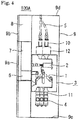
- FIG. 4 is a side cross-sectional view showing the specific product structure of the gas-insulated switchgear of FIG. 3 .
- FIGS. 3 and 4 show the structure of the gas-insulated switchgear when the gas-insulated switchgear is used so that an external cable is led out of an upper portion of the gas-insulated switchgear.
- a gas-insulated switchgear 100 includes a pressure tank 3, buses 4, an external cable 5, a disconnector operating mechanism 6, a circuit breaker operating mechanism 7, and a control box 8 that are received in a housing 9.
- a disconnector 1 and a circuit breaker 2 are received in the pressure tank 3.
- the disconnector operating mechanism 6 operates the disconnector 1.
- the circuit breaker operating mechanism 7 operates the circuit breaker 2.
- the disconnector 1 means a three position disconnector in which the function of a disconnector and the function of a grounding switch are integrated with each other.
- the pressure tank 3 is made of metal, and an insulating gas is sealed in the pressure tank 3. Furthermore, the housing 9 includes a frame and panels so as to surround the periphery of the components.
- a cable-side bushing 10 as an external cable-connecting portion is installed at a portion of the pressure tank 3 that is connected to the external cable 5
- bus-side bushings 11 as bus-connecting portions are installed at a portion of the pressure tank 3 that is connected to the buses 4.
- a door 9a is provided on a portion of the housing 9 that is positioned in front of the disconnector operating mechanism 6 and the circuit breaker operating mechanism 7, and a door 9b is provided on a portion of the housing that is positioned in front of the control box 8. Meanwhile, the installation position of the control box 8 is not changed even though the lead-in direction of the external cable 5 is changed.
- a CT (current transformer) 12 which is a sensor concentrically mounted and measuring a main circuit current, is installed on the outer periphery of the cable-side bushing 10. Meanwhile, the external cable 5, the cable-side bushing 10, the circuit breaker 2, the disconnector 1, the bus-side bushings 11, and the buses 4 are formed in this order as a current flow path.
- the pressure tank 3, the disconnector operating mechanism 6, and the circuit breaker operating mechanism 7, which have been described above, are integrated in advance to form an integrated structure. Moreover, the integrated structure is rotated, supported, and received in the housing 9 in accordance with the lead-in direction of the external cable 5, so that the external cable 5 can be adapted so as to be received and fixed in any aspect of the aspects of FIGS. 2 and 4 .
- FIGS. 1 and 2 show a structure in which the external cable 5 is led in from the lower portion of the gas-insulated switchgear 100, and a gas-insulated switchgear 100A of FIGS. 3 and 4 has a structure in which the external cable 5 is led in from the upper portion of the gas-insulated switchgear.
- the integrated structure which includes the pressure tank 3, the disconnector operating mechanism 6, and the circuit breaker operating mechanism 7, is inverted vertically and supported.
- the housing 9 can easily cope with the inversion of the integrated structure.
- a known technique such as forming an opening into which the external cable 5 is inserted at each of the top plate 9c and the bottom plate 9d and mounting a lid on the opening into which the external cable 5 is not inserted, can be appropriately applied.
- a dial (not shown), which appears during the opening of the door 9a, is installed in front of the disconnector operating mechanism 6 and the circuit breaker operating mechanism 7, and displays an operating direction and the like, be inverted vertically together when the pressure tank 3, the disconnector operating mechanism 6, and the circuit breaker operating mechanism 7 integrated in advance are inverted vertically.
- the cable-side bushing 10 for three phases which is the external cable-connecting portion, is airtightly provided on a through hole (not shown) that is formed at the floor of the pressure tank 3.
- the external cable 5 is electrically connected to a conductor, which is provided in the pressure tank 3, through a conductor passing through the cable-side bushing 10, so that an electric path is formed.
- the bus-side bushings 11 for three phases which are the bus-connecting portions, are airtightly provided on through holes (not shown) that are formed at the upper surface portion of the pressure tank 3.
- the buses 4 are electrically connected to conductors, which are provided in the pressure tank 3, through conductors passing through the bus-side bushings 11, so that a current flow path is formed.
- the bus 4 is, for example, a solid-insulation bus, and it is preferable that the bus 4 be provided with a ground screen. When a solid-insulation bus is used, gas treatment is not necessary. Since the buses 4 are inserted into the bus-side bushings 11 and can be mounted by screwing, work can be performed even in a relatively small space.
- Gas treatment is not necessary in all the combinations A, B, and C. Further, in regard to the respective characteristics, the terminal treatment of A is easiest but a terminal distance of A is long, and a bit of time is required for the terminal treatment of B and C but a terminal distance of B and C is short.
- a gas-insulated switchgear can be selected according to specifications of the delivery destination of the gas-insulated switchgear on the basis of these characteristics.
- the gas-insulated switchgear 100A shown in FIG. 3 has a structure in which the external cable 5 is led in from the upper portion of the housing 9.
- the pressure tank 3 described in the gas-insulated switchgear 100 of FIG. 1 and the disconnector operating mechanism 6 and the circuit breaker operating mechanism 7 installed outside the pressure tank 3 are integrally inverted vertically and the shape of the housing 9 is changed so that the external cable 5 is led in from the upper portion.
- structures such as mounting portions or fixing portions for devices received in the housing 9, are formed in advance so as to correspond to the structures of both the housing 9 and the devices received in the housing 9 so that the pressure tank 3, the disconnector operating mechanism 6, and the circuit breaker operating mechanism 7 are mounted at a height where the minimum space required for the installation of the buses 4 can be ensured from the floor of the gas-insulated switchgear 100A.
- the pressure tank 3 receiving the three position disconnector 1 and the circuit breaker 2, the disconnector operating mechanism 6, and the circuit breaker operating mechanism 7 are adapted so as to be capable of being integrally inverted vertically in accordance with the lead-in direction of the external cable 5, and the top plate 9c and the bottom plate 9d of the housing 9 are changed so as to be capable of being exchanged.
- gas-insulated switchgears 100 and 100A can use the same pressure tank 3 and the same operating mechanism regardless of the lead-in direction of the external cable 5, an effect of stabilizing quality by the complete unitization of assembly and an effect of reducing cost by mass production in comparison with the related art are obtained.
- FIG. 5 is a side cross-sectional view schematically showing the internal layout of a gas-insulated switchgear according to an example not covered by the claims.
- the gas-insulated switchgear 100B of this example uses a pressure tank 3A of which the shape is changed so that a cable-side bushing 10 and bus-side bushings 11 are mounted on the surface perpendicular to the floor.
- the pressure tank 3A is formed in a protruding shape, in which stepped portions 31 and 32 are formed at upper and lower portions of a surface on which the disconnector operating mechanism 6 and the circuit breaker operating mechanism 7 provided on the front surface side (the left side in FIG. 5 ) are mounted, in side view.
- the cable-side bushing 10 is mounted on the stepped portion 31 that forms one vertical surface formed in a stepped shape, and the bus-side bushings 11 are mounted on the stepped portion 32 that forms the other vertical surface.
- the height of the housing 9 on which the buses 4 for three phases are arranged in the vertical direction is greater than that of the housing of the gas-insulated switchgear 100 described in the embodiment.
- the pressure tank 3A, the disconnector operating mechanism 6, and the circuit breaker operating mechanism 7 only have to be integrally inverted vertically and received and fixed to the housing 9.
- the pressure tank 3A, the disconnector operating mechanism 6, and the circuit breaker operating mechanism 7 are mounted at a height where the minimum space required for the installation of the buses 4 can be ensured.
Landscapes
- Engineering & Computer Science (AREA)
- Power Engineering (AREA)
- Gas-Insulated Switchgears (AREA)
Claims (1)
- Gasisolierte Schaltanlage (100), die Folgendes aufweist:- einen Druckbehälter (3), in dem ein Leistungsschalter (2) und ein Trennschalter (1) untergebracht sind ist und ein Isoliergas eingeschlossen ist;- einen Leistungsschalter-Betätigungsmechanismus (7), der außerhalb des Druckbehälters (3) angeordnet ist und den Leistungsschalter (2) betätigt;- einen Trennschalter-Betätigungsmechanismus (6), der außerhalb des Drucktanks (3) angeordnet ist und den Trennschalter (1) betätigt; und- ein Gehäuse (9), in dem der Druckbehälter (3), der Leistungsschalter-Betätigungsmechanismus (7) und der Trennschalter-Betätigungsmechanismus (6) untergebracht sind,- wobei der Drucktank (3), der Leistungsschalter-Betätigungsmechanismus (7) und der Trennschalter-Betätigungsmechanismus (6) eine integrierte Struktur bilden und in dem Gehäuse (9) untergebracht sind,dadurch gekennzeichnet,
dass das Gehäuse (9) und die integrierte Struktur so ausgebildet sind, dass sie eine Montage der integrierten Struktur in einer ersten Orientierung ermöglichen, derart, dass eine kabelseitige Buchse (10) und busseitige Buchsen (11), die auf gegenüberliegenden Seiten des Druckbehälters (3) angeordnet sind, mit Bussen (4) bzw. einem externen Kabel (5) ausgerichtet sind,- wenn das externe Kabel (5) vom unteren Bereich des Gehäuses (9) aus eingeführt ist, und in einer zweiten Ausrichtung, vertikal entgegengesetzt in Bezug auf die erste Ausrichtung, wenn das externe Kabel (5) vom oberen Bereich des Gehäuses (9) aus eingeführt ist, und- wobei das Gehäuse (9) so bemessen ist, dass sichergestellt ist, dass ein Raum unterhalb der integrierten Struktur gerade groß genug ist, um das Anschließen des externen Kabels (5) in der ersten Ausrichtung und den minimalen Raum vom Boden der gasisolierten Schaltanlage für die Installation von Bussen (4) in der zweiten Ausrichtung zu ermöglichen, so dass die Höhe des Gehäuses (9) minimiert ist.
Applications Claiming Priority (1)
| Application Number | Priority Date | Filing Date | Title |
|---|---|---|---|
| PCT/JP2014/061921 WO2015166545A1 (ja) | 2014-04-29 | 2014-04-29 | ガス絶縁スイッチギヤ |
Publications (3)
| Publication Number | Publication Date |
|---|---|
| EP2953219A1 EP2953219A1 (de) | 2015-12-09 |
| EP2953219A4 EP2953219A4 (de) | 2016-04-13 |
| EP2953219B1 true EP2953219B1 (de) | 2021-05-26 |
Family
ID=52145667
Family Applications (1)
| Application Number | Title | Priority Date | Filing Date |
|---|---|---|---|
| EP14864994.0A Active EP2953219B1 (de) | 2014-04-29 | 2014-04-29 | Gasisolierte schaltanlage |
Country Status (4)
| Country | Link |
|---|---|
| EP (1) | EP2953219B1 (de) |
| JP (1) | JP5638726B1 (de) |
| CN (1) | CN105229879B (de) |
| WO (1) | WO2015166545A1 (de) |
Families Citing this family (4)
| Publication number | Priority date | Publication date | Assignee | Title |
|---|---|---|---|---|
| CN108988191B (zh) * | 2018-09-30 | 2023-06-02 | 聂刚 | 一种气体绝缘金属封闭开关设备 |
| EP3671986B1 (de) | 2018-12-19 | 2025-05-14 | ABB Schweiz AG | Schaltanlage |
| EP3671991B1 (de) * | 2018-12-19 | 2025-04-23 | ABB Schweiz AG | Dreiphasige schaltanlage |
| EP4546580A3 (de) * | 2018-12-19 | 2025-07-02 | Abb Schweiz Ag | Dreiphasige schaltanlage mit einphasiger ausrüstung in einem gehäuse |
Family Cites Families (8)
| Publication number | Priority date | Publication date | Assignee | Title |
|---|---|---|---|---|
| DE4103101C3 (de) * | 1990-03-22 | 1996-08-14 | Mitsubishi Electric Corp | Trennschalter, sowie Druckgas-isoliertes Schaltgetriebe mit solchem |
| JPH0574109U (ja) * | 1992-03-09 | 1993-10-08 | 日新電機株式会社 | ガス絶縁開閉装置 |
| JPH08340610A (ja) * | 1995-06-09 | 1996-12-24 | Fuji Electric Co Ltd | ガス絶縁開閉装置 |
| JP2001169420A (ja) * | 1999-12-07 | 2001-06-22 | Meidensha Corp | ガス絶縁開閉装置 |
| JP2001352623A (ja) * | 2000-06-02 | 2001-12-21 | Mitsubishi Electric Corp | ガス絶縁開閉装置 |
| CN2574270Y (zh) * | 2002-10-08 | 2003-09-17 | 李彤 | 一种六氟化硫气体绝缘金属封闭开关设备 |
| JP4329923B2 (ja) * | 2002-10-31 | 2009-09-09 | 三菱電機株式会社 | ガス絶縁スイッチギヤ |
| CN2919626Y (zh) * | 2006-04-29 | 2007-07-04 | 江苏宝胜电气股份有限公司 | 数字化三相一体充气隔室模块 |
-
2014
- 2014-04-29 CN CN201480003421.8A patent/CN105229879B/zh active Active
- 2014-04-29 EP EP14864994.0A patent/EP2953219B1/de active Active
- 2014-04-29 JP JP2014534684A patent/JP5638726B1/ja active Active
- 2014-04-29 WO PCT/JP2014/061921 patent/WO2015166545A1/ja not_active Ceased
Non-Patent Citations (1)
| Title |
|---|
| None * |
Also Published As
| Publication number | Publication date |
|---|---|
| WO2015166545A1 (ja) | 2015-11-05 |
| EP2953219A1 (de) | 2015-12-09 |
| CN105229879B (zh) | 2018-05-29 |
| JP5638726B1 (ja) | 2014-12-10 |
| HK1214415A1 (zh) | 2016-07-22 |
| EP2953219A4 (de) | 2016-04-13 |
| JPWO2015166545A1 (ja) | 2017-04-20 |
| CN105229879A (zh) | 2016-01-06 |
Similar Documents
| Publication | Publication Date | Title |
|---|---|---|
| TWI442661B (zh) | Switchgear | |
| CN102428535B (zh) | 电气式功率开关和带有功率开关的开关板 | |
| KR100984509B1 (ko) | 고압 배전반 | |
| CN101540484B (zh) | 开关机构 | |
| EP2953219B1 (de) | Gasisolierte schaltanlage | |
| EP1107408A1 (de) | Gasisolierte Schaltanlage | |
| CN102122802B (zh) | 真空绝缘开关设备及其制造方法、相关部件更换调整方法 | |
| JP6338795B1 (ja) | ガス絶縁開閉装置 | |
| US10601204B2 (en) | Electrical unit for a motor control center with ingress protection | |
| US9667041B2 (en) | Electrically insulating cover for terminal assembly | |
| EP3280016B1 (de) | Gasisoliertes schaltgetriebe | |
| CN208753687U (zh) | 高压屏蔽线转接器 | |
| CN102576622B (zh) | 气体绝缘的中压开关设备 | |
| JP5787275B2 (ja) | スイッチギヤ | |
| KR101189520B1 (ko) | 전압 감지 기능을 내장한 고?저압 벽관통형 부싱 | |
| US11289885B2 (en) | Gas-insulated switchgear | |
| CN101496119A (zh) | 用于安装在安全壳体内的连接件 | |
| JP6562755B2 (ja) | スイッチギヤ | |
| CN205248622U (zh) | 开关柜及其具备母排支撑功能的电压互感器 | |
| JPH0382309A (ja) | 配電盤 | |
| JP6398651B2 (ja) | スイッチギヤ | |
| HK1214415B (en) | Gas-insulated switchgear | |
| EP3829012B1 (de) | Gasisolationsschaltgetriebe | |
| CN100474720C (zh) | 气体绝缘开关设备 | |
| EP2940812B1 (de) | Schaltanlage |
Legal Events
| Date | Code | Title | Description |
|---|---|---|---|
| PUAI | Public reference made under article 153(3) epc to a published international application that has entered the european phase |
Free format text: ORIGINAL CODE: 0009012 |
|
| 17P | Request for examination filed |
Effective date: 20150603 |
|
| AK | Designated contracting states |
Kind code of ref document: A1 Designated state(s): AL AT BE BG CH CY CZ DE DK EE ES FI FR GB GR HR HU IE IS IT LI LT LU LV MC MK MT NL NO PL PT RO RS SE SI SK SM TR |
|
| AX | Request for extension of the european patent |
Extension state: BA ME |
|
| A4 | Supplementary search report drawn up and despatched |
Effective date: 20160315 |
|
| RIC1 | Information provided on ipc code assigned before grant |
Ipc: H02B 13/02 20060101AFI20160309BHEP Ipc: H02B 13/035 20060101ALN20160309BHEP |
|
| STAA | Information on the status of an ep patent application or granted ep patent |
Free format text: STATUS: EXAMINATION IS IN PROGRESS |
|
| 17Q | First examination report despatched |
Effective date: 20161213 |
|
| DAX | Request for extension of the european patent (deleted) | ||
| GRAP | Despatch of communication of intention to grant a patent |
Free format text: ORIGINAL CODE: EPIDOSNIGR1 |
|
| STAA | Information on the status of an ep patent application or granted ep patent |
Free format text: STATUS: GRANT OF PATENT IS INTENDED |
|
| INTG | Intention to grant announced |
Effective date: 20201124 |
|
| GRAS | Grant fee paid |
Free format text: ORIGINAL CODE: EPIDOSNIGR3 |
|
| GRAA | (expected) grant |
Free format text: ORIGINAL CODE: 0009210 |
|
| STAA | Information on the status of an ep patent application or granted ep patent |
Free format text: STATUS: THE PATENT HAS BEEN GRANTED |
|
| AK | Designated contracting states |
Kind code of ref document: B1 Designated state(s): AL AT BE BG CH CY CZ DE DK EE ES FI FR GB GR HR HU IE IS IT LI LT LU LV MC MK MT NL NO PL PT RO RS SE SI SK SM TR |
|
| REG | Reference to a national code |
Ref country code: GB Ref legal event code: FG4D |
|
| REG | Reference to a national code |
Ref country code: CH Ref legal event code: EP |
|
| REG | Reference to a national code |
Ref country code: AT Ref legal event code: REF Ref document number: 1397189 Country of ref document: AT Kind code of ref document: T Effective date: 20210615 |
|
| REG | Reference to a national code |
Ref country code: DE Ref legal event code: R096 Ref document number: 602014077795 Country of ref document: DE |
|
| REG | Reference to a national code |
Ref country code: IE Ref legal event code: FG4D |
|
| REG | Reference to a national code |
Ref country code: LT Ref legal event code: MG9D |
|
| REG | Reference to a national code |
Ref country code: AT Ref legal event code: MK05 Ref document number: 1397189 Country of ref document: AT Kind code of ref document: T Effective date: 20210526 |
|
| PG25 | Lapsed in a contracting state [announced via postgrant information from national office to epo] |
Ref country code: FI Free format text: LAPSE BECAUSE OF FAILURE TO SUBMIT A TRANSLATION OF THE DESCRIPTION OR TO PAY THE FEE WITHIN THE PRESCRIBED TIME-LIMIT Effective date: 20210526 Ref country code: LT Free format text: LAPSE BECAUSE OF FAILURE TO SUBMIT A TRANSLATION OF THE DESCRIPTION OR TO PAY THE FEE WITHIN THE PRESCRIBED TIME-LIMIT Effective date: 20210526 Ref country code: AT Free format text: LAPSE BECAUSE OF FAILURE TO SUBMIT A TRANSLATION OF THE DESCRIPTION OR TO PAY THE FEE WITHIN THE PRESCRIBED TIME-LIMIT Effective date: 20210526 Ref country code: BG Free format text: LAPSE BECAUSE OF FAILURE TO SUBMIT A TRANSLATION OF THE DESCRIPTION OR TO PAY THE FEE WITHIN THE PRESCRIBED TIME-LIMIT Effective date: 20210826 Ref country code: HR Free format text: LAPSE BECAUSE OF FAILURE TO SUBMIT A TRANSLATION OF THE DESCRIPTION OR TO PAY THE FEE WITHIN THE PRESCRIBED TIME-LIMIT Effective date: 20210526 |
|
| REG | Reference to a national code |
Ref country code: NL Ref legal event code: MP Effective date: 20210526 |
|
| PG25 | Lapsed in a contracting state [announced via postgrant information from national office to epo] |
Ref country code: NO Free format text: LAPSE BECAUSE OF FAILURE TO SUBMIT A TRANSLATION OF THE DESCRIPTION OR TO PAY THE FEE WITHIN THE PRESCRIBED TIME-LIMIT Effective date: 20210826 Ref country code: PT Free format text: LAPSE BECAUSE OF FAILURE TO SUBMIT A TRANSLATION OF THE DESCRIPTION OR TO PAY THE FEE WITHIN THE PRESCRIBED TIME-LIMIT Effective date: 20210927 Ref country code: PL Free format text: LAPSE BECAUSE OF FAILURE TO SUBMIT A TRANSLATION OF THE DESCRIPTION OR TO PAY THE FEE WITHIN THE PRESCRIBED TIME-LIMIT Effective date: 20210526 Ref country code: RS Free format text: LAPSE BECAUSE OF FAILURE TO SUBMIT A TRANSLATION OF THE DESCRIPTION OR TO PAY THE FEE WITHIN THE PRESCRIBED TIME-LIMIT Effective date: 20210526 Ref country code: SE Free format text: LAPSE BECAUSE OF FAILURE TO SUBMIT A TRANSLATION OF THE DESCRIPTION OR TO PAY THE FEE WITHIN THE PRESCRIBED TIME-LIMIT Effective date: 20210526 Ref country code: LV Free format text: LAPSE BECAUSE OF FAILURE TO SUBMIT A TRANSLATION OF THE DESCRIPTION OR TO PAY THE FEE WITHIN THE PRESCRIBED TIME-LIMIT Effective date: 20210526 Ref country code: IS Free format text: LAPSE BECAUSE OF FAILURE TO SUBMIT A TRANSLATION OF THE DESCRIPTION OR TO PAY THE FEE WITHIN THE PRESCRIBED TIME-LIMIT Effective date: 20210926 Ref country code: GR Free format text: LAPSE BECAUSE OF FAILURE TO SUBMIT A TRANSLATION OF THE DESCRIPTION OR TO PAY THE FEE WITHIN THE PRESCRIBED TIME-LIMIT Effective date: 20210827 |
|
| PG25 | Lapsed in a contracting state [announced via postgrant information from national office to epo] |
Ref country code: NL Free format text: LAPSE BECAUSE OF FAILURE TO SUBMIT A TRANSLATION OF THE DESCRIPTION OR TO PAY THE FEE WITHIN THE PRESCRIBED TIME-LIMIT Effective date: 20210526 |
|
| PG25 | Lapsed in a contracting state [announced via postgrant information from national office to epo] |
Ref country code: SK Free format text: LAPSE BECAUSE OF FAILURE TO SUBMIT A TRANSLATION OF THE DESCRIPTION OR TO PAY THE FEE WITHIN THE PRESCRIBED TIME-LIMIT Effective date: 20210526 Ref country code: SM Free format text: LAPSE BECAUSE OF FAILURE TO SUBMIT A TRANSLATION OF THE DESCRIPTION OR TO PAY THE FEE WITHIN THE PRESCRIBED TIME-LIMIT Effective date: 20210526 Ref country code: EE Free format text: LAPSE BECAUSE OF FAILURE TO SUBMIT A TRANSLATION OF THE DESCRIPTION OR TO PAY THE FEE WITHIN THE PRESCRIBED TIME-LIMIT Effective date: 20210526 Ref country code: DK Free format text: LAPSE BECAUSE OF FAILURE TO SUBMIT A TRANSLATION OF THE DESCRIPTION OR TO PAY THE FEE WITHIN THE PRESCRIBED TIME-LIMIT Effective date: 20210526 Ref country code: CZ Free format text: LAPSE BECAUSE OF FAILURE TO SUBMIT A TRANSLATION OF THE DESCRIPTION OR TO PAY THE FEE WITHIN THE PRESCRIBED TIME-LIMIT Effective date: 20210526 Ref country code: ES Free format text: LAPSE BECAUSE OF FAILURE TO SUBMIT A TRANSLATION OF THE DESCRIPTION OR TO PAY THE FEE WITHIN THE PRESCRIBED TIME-LIMIT Effective date: 20210526 Ref country code: RO Free format text: LAPSE BECAUSE OF FAILURE TO SUBMIT A TRANSLATION OF THE DESCRIPTION OR TO PAY THE FEE WITHIN THE PRESCRIBED TIME-LIMIT Effective date: 20210526 |
|
| REG | Reference to a national code |
Ref country code: DE Ref legal event code: R097 Ref document number: 602014077795 Country of ref document: DE |
|
| PLBE | No opposition filed within time limit |
Free format text: ORIGINAL CODE: 0009261 |
|
| STAA | Information on the status of an ep patent application or granted ep patent |
Free format text: STATUS: NO OPPOSITION FILED WITHIN TIME LIMIT |
|
| 26N | No opposition filed |
Effective date: 20220301 |
|
| PG25 | Lapsed in a contracting state [announced via postgrant information from national office to epo] |
Ref country code: IS Free format text: LAPSE BECAUSE OF FAILURE TO SUBMIT A TRANSLATION OF THE DESCRIPTION OR TO PAY THE FEE WITHIN THE PRESCRIBED TIME-LIMIT Effective date: 20210926 Ref country code: AL Free format text: LAPSE BECAUSE OF FAILURE TO SUBMIT A TRANSLATION OF THE DESCRIPTION OR TO PAY THE FEE WITHIN THE PRESCRIBED TIME-LIMIT Effective date: 20210526 |
|
| PG25 | Lapsed in a contracting state [announced via postgrant information from national office to epo] |
Ref country code: IT Free format text: LAPSE BECAUSE OF FAILURE TO SUBMIT A TRANSLATION OF THE DESCRIPTION OR TO PAY THE FEE WITHIN THE PRESCRIBED TIME-LIMIT Effective date: 20210526 |
|
| REG | Reference to a national code |
Ref country code: CH Ref legal event code: PL |
|
| GBPC | Gb: european patent ceased through non-payment of renewal fee |
Effective date: 20220429 |
|
| REG | Reference to a national code |
Ref country code: BE Ref legal event code: MM Effective date: 20220430 |
|
| PG25 | Lapsed in a contracting state [announced via postgrant information from national office to epo] |
Ref country code: MC Free format text: LAPSE BECAUSE OF FAILURE TO SUBMIT A TRANSLATION OF THE DESCRIPTION OR TO PAY THE FEE WITHIN THE PRESCRIBED TIME-LIMIT Effective date: 20210526 Ref country code: LU Free format text: LAPSE BECAUSE OF NON-PAYMENT OF DUE FEES Effective date: 20220429 Ref country code: LI Free format text: LAPSE BECAUSE OF NON-PAYMENT OF DUE FEES Effective date: 20220430 Ref country code: GB Free format text: LAPSE BECAUSE OF NON-PAYMENT OF DUE FEES Effective date: 20220429 Ref country code: CH Free format text: LAPSE BECAUSE OF NON-PAYMENT OF DUE FEES Effective date: 20220430 |
|
| PG25 | Lapsed in a contracting state [announced via postgrant information from national office to epo] |
Ref country code: BE Free format text: LAPSE BECAUSE OF NON-PAYMENT OF DUE FEES Effective date: 20220430 |
|
| PG25 | Lapsed in a contracting state [announced via postgrant information from national office to epo] |
Ref country code: IE Free format text: LAPSE BECAUSE OF NON-PAYMENT OF DUE FEES Effective date: 20220429 |
|
| P01 | Opt-out of the competence of the unified patent court (upc) registered |
Effective date: 20230512 |
|
| PG25 | Lapsed in a contracting state [announced via postgrant information from national office to epo] |
Ref country code: HU Free format text: LAPSE BECAUSE OF FAILURE TO SUBMIT A TRANSLATION OF THE DESCRIPTION OR TO PAY THE FEE WITHIN THE PRESCRIBED TIME-LIMIT; INVALID AB INITIO Effective date: 20140429 |
|
| PG25 | Lapsed in a contracting state [announced via postgrant information from national office to epo] |
Ref country code: MK Free format text: LAPSE BECAUSE OF FAILURE TO SUBMIT A TRANSLATION OF THE DESCRIPTION OR TO PAY THE FEE WITHIN THE PRESCRIBED TIME-LIMIT Effective date: 20210526 Ref country code: CY Free format text: LAPSE BECAUSE OF FAILURE TO SUBMIT A TRANSLATION OF THE DESCRIPTION OR TO PAY THE FEE WITHIN THE PRESCRIBED TIME-LIMIT Effective date: 20210526 |
|
| PG25 | Lapsed in a contracting state [announced via postgrant information from national office to epo] |
Ref country code: TR Free format text: LAPSE BECAUSE OF FAILURE TO SUBMIT A TRANSLATION OF THE DESCRIPTION OR TO PAY THE FEE WITHIN THE PRESCRIBED TIME-LIMIT Effective date: 20210526 |
|
| PG25 | Lapsed in a contracting state [announced via postgrant information from national office to epo] |
Ref country code: MT Free format text: LAPSE BECAUSE OF FAILURE TO SUBMIT A TRANSLATION OF THE DESCRIPTION OR TO PAY THE FEE WITHIN THE PRESCRIBED TIME-LIMIT Effective date: 20210526 |
|
| REG | Reference to a national code |
Ref country code: DE Ref legal event code: R084 Ref document number: 602014077795 Country of ref document: DE |
|
| PGFP | Annual fee paid to national office [announced via postgrant information from national office to epo] |
Ref country code: DE Payment date: 20250305 Year of fee payment: 12 |
|
| PGFP | Annual fee paid to national office [announced via postgrant information from national office to epo] |
Ref country code: FR Payment date: 20260309 Year of fee payment: 13 |