EP2954541B1 - Linearaktuator - Google Patents
Linearaktuator Download PDFInfo
- Publication number
- EP2954541B1 EP2954541B1 EP14703403.7A EP14703403A EP2954541B1 EP 2954541 B1 EP2954541 B1 EP 2954541B1 EP 14703403 A EP14703403 A EP 14703403A EP 2954541 B1 EP2954541 B1 EP 2954541B1
- Authority
- EP
- European Patent Office
- Prior art keywords
- linear actuator
- magnetic armature
- actuator according
- armature
- actuator
- Prior art date
- Legal status (The legal status is an assumption and is not a legal conclusion. Google has not performed a legal analysis and makes no representation as to the accuracy of the status listed.)
- Not-in-force
Links
Images

Classifications
-
- H—ELECTRICITY
- H02—GENERATION; CONVERSION OR DISTRIBUTION OF ELECTRIC POWER
- H02K—DYNAMO-ELECTRIC MACHINES
- H02K41/00—Propulsion systems in which a rigid body is moved along a path due to dynamo-electric interaction between the body and a magnetic field travelling along the path
- H02K41/02—Linear motors; Sectional motors
-
- H—ELECTRICITY
- H02—GENERATION; CONVERSION OR DISTRIBUTION OF ELECTRIC POWER
- H02K—DYNAMO-ELECTRIC MACHINES
- H02K33/00—Motors with reciprocating, oscillating or vibrating magnet, armature or coil system
- H02K33/16—Motors with reciprocating, oscillating or vibrating magnet, armature or coil system with polarised armatures moving in alternate directions by reversal or energisation of a single coil system
-
- B—PERFORMING OPERATIONS; TRANSPORTING
- B60—VEHICLES IN GENERAL
- B60K—ARRANGEMENT OR MOUNTING OF PROPULSION UNITS OR OF TRANSMISSIONS IN VEHICLES; ARRANGEMENT OR MOUNTING OF PLURAL DIVERSE PRIME-MOVERS IN VEHICLES; AUXILIARY DRIVES FOR VEHICLES; INSTRUMENTATION OR DASHBOARDS FOR VEHICLES; ARRANGEMENTS IN CONNECTION WITH COOLING, AIR INTAKE, GAS EXHAUST OR FUEL SUPPLY OF PROPULSION UNITS IN VEHICLES
- B60K5/00—Arrangement or mounting of internal-combustion or jet-propulsion units
- B60K5/12—Arrangement of engine supports
- B60K5/1283—Adjustable supports, e.g. the mounting or the characteristics being adjustable
-
- F—MECHANICAL ENGINEERING; LIGHTING; HEATING; WEAPONS; BLASTING
- F16—ENGINEERING ELEMENTS AND UNITS; GENERAL MEASURES FOR PRODUCING AND MAINTAINING EFFECTIVE FUNCTIONING OF MACHINES OR INSTALLATIONS; THERMAL INSULATION IN GENERAL
- F16C—SHAFTS; FLEXIBLE SHAFTS; ELEMENTS OR CRANKSHAFT MECHANISMS; ROTARY BODIES OTHER THAN GEARING ELEMENTS; BEARINGS
- F16C32/00—Bearings not otherwise provided for
- F16C32/04—Bearings not otherwise provided for using magnetic or electric supporting means
- F16C32/0406—Magnetic bearings
- F16C32/044—Active magnetic bearings
- F16C32/0472—Active magnetic bearings for linear movement
-
- H—ELECTRICITY
- H01—ELECTRIC ELEMENTS
- H01F—MAGNETS; INDUCTANCES; TRANSFORMERS; SELECTION OF MATERIALS FOR THEIR MAGNETIC PROPERTIES
- H01F7/00—Magnets
- H01F7/06—Electromagnets; Actuators including electromagnets
- H01F7/08—Electromagnets; Actuators including electromagnets with armatures
- H01F7/16—Rectilinearly-movable armatures
- H01F7/1607—Armatures entering the winding
-
- H—ELECTRICITY
- H02—GENERATION; CONVERSION OR DISTRIBUTION OF ELECTRIC POWER
- H02K—DYNAMO-ELECTRIC MACHINES
- H02K1/00—Details of the magnetic circuit
- H02K1/06—Details of the magnetic circuit characterised by the shape, form or construction
- H02K1/22—Rotating parts of the magnetic circuit
- H02K1/28—Means for mounting or fastening rotating magnetic parts on to, or to, the rotor structures
- H02K1/30—Means for mounting or fastening rotating magnetic parts on to, or to, the rotor structures using intermediate parts, e.g. spiders
-
- F—MECHANICAL ENGINEERING; LIGHTING; HEATING; WEAPONS; BLASTING
- F16—ENGINEERING ELEMENTS AND UNITS; GENERAL MEASURES FOR PRODUCING AND MAINTAINING EFFECTIVE FUNCTIONING OF MACHINES OR INSTALLATIONS; THERMAL INSULATION IN GENERAL
- F16C—SHAFTS; FLEXIBLE SHAFTS; ELEMENTS OR CRANKSHAFT MECHANISMS; ROTARY BODIES OTHER THAN GEARING ELEMENTS; BEARINGS
- F16C32/00—Bearings not otherwise provided for
- F16C32/04—Bearings not otherwise provided for using magnetic or electric supporting means
- F16C32/0406—Magnetic bearings
- F16C32/044—Active magnetic bearings
- F16C32/0459—Details of the magnetic circuit
- F16C32/0468—Details of the magnetic circuit of moving parts of the magnetic circuit, e.g. of the rotor
-
- F—MECHANICAL ENGINEERING; LIGHTING; HEATING; WEAPONS; BLASTING
- F16—ENGINEERING ELEMENTS AND UNITS; GENERAL MEASURES FOR PRODUCING AND MAINTAINING EFFECTIVE FUNCTIONING OF MACHINES OR INSTALLATIONS; THERMAL INSULATION IN GENERAL
- F16F—SPRINGS; SHOCK-ABSORBERS; MEANS FOR DAMPING VIBRATION
- F16F13/00—Units comprising springs of the non-fluid type as well as vibration-dampers, shock-absorbers, or fluid springs
-
- F—MECHANICAL ENGINEERING; LIGHTING; HEATING; WEAPONS; BLASTING
- F16—ENGINEERING ELEMENTS AND UNITS; GENERAL MEASURES FOR PRODUCING AND MAINTAINING EFFECTIVE FUNCTIONING OF MACHINES OR INSTALLATIONS; THERMAL INSULATION IN GENERAL
- F16F—SPRINGS; SHOCK-ABSORBERS; MEANS FOR DAMPING VIBRATION
- F16F13/00—Units comprising springs of the non-fluid type as well as vibration-dampers, shock-absorbers, or fluid springs
- F16F13/04—Units comprising springs of the non-fluid type as well as vibration-dampers, shock-absorbers, or fluid springs comprising both a plastics spring and a damper, e.g. a friction damper
- F16F13/06—Units comprising springs of the non-fluid type as well as vibration-dampers, shock-absorbers, or fluid springs comprising both a plastics spring and a damper, e.g. a friction damper the damper being a fluid damper, e.g. the plastics spring not forming a part of the wall of the fluid chamber of the damper
- F16F13/08—Units comprising springs of the non-fluid type as well as vibration-dampers, shock-absorbers, or fluid springs comprising both a plastics spring and a damper, e.g. a friction damper the damper being a fluid damper, e.g. the plastics spring not forming a part of the wall of the fluid chamber of the damper the plastics spring forming at least a part of the wall of the fluid chamber of the damper
- F16F13/14—Units of the bushing type, i.e. loaded predominantly radially
- F16F13/149—Multiple bushings connected together; Restraining links
-
- F—MECHANICAL ENGINEERING; LIGHTING; HEATING; WEAPONS; BLASTING
- F16—ENGINEERING ELEMENTS AND UNITS; GENERAL MEASURES FOR PRODUCING AND MAINTAINING EFFECTIVE FUNCTIONING OF MACHINES OR INSTALLATIONS; THERMAL INSULATION IN GENERAL
- F16F—SPRINGS; SHOCK-ABSORBERS; MEANS FOR DAMPING VIBRATION
- F16F13/00—Units comprising springs of the non-fluid type as well as vibration-dampers, shock-absorbers, or fluid springs
- F16F13/04—Units comprising springs of the non-fluid type as well as vibration-dampers, shock-absorbers, or fluid springs comprising both a plastics spring and a damper, e.g. a friction damper
- F16F13/26—Units comprising springs of the non-fluid type as well as vibration-dampers, shock-absorbers, or fluid springs comprising both a plastics spring and a damper, e.g. a friction damper characterised by adjusting or regulating devices responsive to exterior conditions
-
- F—MECHANICAL ENGINEERING; LIGHTING; HEATING; WEAPONS; BLASTING
- F16—ENGINEERING ELEMENTS AND UNITS; GENERAL MEASURES FOR PRODUCING AND MAINTAINING EFFECTIVE FUNCTIONING OF MACHINES OR INSTALLATIONS; THERMAL INSULATION IN GENERAL
- F16F—SPRINGS; SHOCK-ABSORBERS; MEANS FOR DAMPING VIBRATION
- F16F5/00—Liquid springs in which the liquid works as a spring by compression, e.g. combined with throttling action; Combinations of devices including liquid springs
-
- H—ELECTRICITY
- H01—ELECTRIC ELEMENTS
- H01F—MAGNETS; INDUCTANCES; TRANSFORMERS; SELECTION OF MATERIALS FOR THEIR MAGNETIC PROPERTIES
- H01F7/00—Magnets
- H01F7/06—Electromagnets; Actuators including electromagnets
- H01F7/08—Electromagnets; Actuators including electromagnets with armatures
- H01F7/081—Magnetic constructions
- H01F2007/086—Structural details of the armature
Definitions
- the present invention relates to a linear actuator, in particular for use in an active engine mount of a vehicle.
- active engine mounts can be used to improve comfort.
- unwanted vibrations and thereby caused noise transmission into the interior of the vehicle can be suppressed or at least reduced.
- Unwanted vibrations may occur, for example, in a cylinder deactivation of the engine, when one or more of the cylinders of the engine are turned off, the engine can run rough.
- An active engine mount for this purpose has a control for one or more actuators, in order to counteract the vibrations of the motor by means of the actuators in a manner familiar to those skilled in the art.
- the actuators can in particular be linear actuators which are operated electromagnetically.
- a linear actuator usually has a stator with an electrically energizable coil for generating an electromagnetic field and an axially movable with respect to the stator mounted actuator with a magnet armature.
- the actuator also has an axially extending ram for actuating the active engine mount. It is advantageous to mount the actuator in the stator, for example by means of a spring element, in such a way that it can be moved axially without friction.
- EP 0 181 056 A shows a switching magnet arrangement, wherein the actuator is axially movably mounted in a cylindrical Magentraum formed by a stator, wherein the actuator has a support element made of aluminum or plastic for a plunger and against the plunger axially to a solid magnetically filling the magnetic space magnet armature bordered by interlocking complementary conical surfaces.
- EP0258568 shows an electromagnetic actuator consisting of a coaxial in a hollow cylindrical permanent magnet combination of bobbin and coil winding.
- the bobbin is supported at both ends by disc-shaped springs.
- the actuator comprises a carrier element which extends in the radial direction between the armature and the plunger.
- the support member is made of a non-magnetic material having a lower density than the armature.
- the armature thus does not reach up to the plunger zoom, but is supported by a support member which may be formed in an advantageous lightweight construction.
- the weight of the actuator can be reduced, which has a positive effect on the behavior of the linear actuator even at high frequency vibrations.
- the reduced mass inertia of the actuator improves the response, since in particular in a reversal of the energization of the coil, the inversion of the actuator is reduced.
- the invention is based on the finding that the spatial extent of the magnet armature, which consists of a relatively heavy magnetic material, can be reduced without this having a significant effect on the magnetic force acting on the magnet armature. Therefore, the radially inner part of the actuator can be replaced by a non-magnetic, lighter material. Because it has unexpectedly been found that run in this area almost no field lines of the electromagnetic field of the coil. This means that in this area at most an unordered leakage flux of the magnetic field occurs, which, however, has no influence on the magnetic force. The relevant field lines run in a closed circle in the iron circle of the linear actuator, in particular by the magnet armature.
- the magnet armature and the carrier element are therefore preferably dimensioned such that an enlargement of the magnet armature in the radial direction does not increase or at least substantially increase, for example a maximum of 5%, of the operation generated by the electromagnetic field and acting on the actuator Magnetic force would cause.
- the spatial extent and the mass of the armature are reduced to a minimum in a given structure of the stator and a predetermined current level, with which the coil is energized. It is not necessary to increase the magnet armature radially inwardly in the direction of the plunger and to reduce the carrier element accordingly, since, as explained, no relevant field lines of the electromagnetic field run in this region. The relevant field lines pass through the magnet armature.
- the armature is thus reduced to its magnetically relevant volume.
- a further reduction of the magnet armature would lead to a throttling of the magnetic field and to a negative influence on the field lines, which would result in a reduction of the magnetic force.
- the armature is annular and surrounds the carrier element.
- the armature thus occupies that part of the actuator which is adjacent to the coil and therefore particularly relevant to the action of the magnetic field.
- the annular magnet armature is formed as narrow as possible, wherein the ratio of the outer diameter of the magnet armature to the inner diameter of the magnet armature is at most 2: 1, preferably at most 1.5: 1 and more preferably at most 1.25: 1.
- the magnet armature thus preferably occupies at most half, more preferably at most one third and even more preferably at most one fifth.
- the cross section of the armature tapers inwardly in the axial direction.
- the shape of the cross section of the magnet armature can be used to reduce the volume of the armature, without negatively affecting the force balance of the magnetic force.
- the cross section of the magnet armature can be reduced from radially inward, wherein the field lines of the electromagnetic field are not disturbed.
- one corner or two corners can be removed from radially inward so that, for example, an approximately trapezoidal cross-section is created.
- Other radially inwardly tapering cross-sectional shapes are also possible, such as a trapezoidal shape with rounded corners, a round shape or even a concave shape, as long as the course of the field lines is not hindered by the armature.
- the carrier element comprises a lightweight construction material or substantially completely consists thereof, such as aluminum, magnesium, plastic and / or a fiber composite material.
- the actuator comprises at least one permanent magnet which adjoins the magnet armature and is preferably arranged on the outer circumference of the magnet armature.
- two permanent magnets spaced apart in the axial direction and preferably magnetized in the radial direction may be provided.
- the permanent magnets which may also be referred to as permanent magnets, are of particular importance when the iron circle of the linear actuator does not comprise a stationary pole part or a direction of movement of the actuator which depends on the polarity of the exciting current is desired.
- the axial displacement of the actuator is then caused by the force acting on the armature magnetic force of the magnetic field, which is composed of the electromagnetic field of the energized coil and the magnetic field of the permanent magnet.
- the carrier element has openings and can preferably at least partially in the axial direction a smaller
- the support member may also have recesses to save weight. These measures serve to further reduce the volume and thus the mass of the support element.
- the extent, the arrangement, the configuration and the shape of the perforations and / or recesses in the carrier element are dependent in particular on the material used of the carrier element and also on the application of magnetic forces, in such a way that the mechanical stability of the carrier element is not affected is.
- the openings may have any shape and extend in the axial direction. It is also possible not to provide completely through the support member passing through openings, but only to form recesses on one or both axial sides of the support member.
- the carrier element has a magnet armature bearing radially outer part and a ram supporting radially inner part, which are connected to each other via spoke-like webs.
- the carrier element can be designed like a rim and the magnet armature can be seated on the outer circumference of the carrier element.
- the carrier element may comprise at least one deep-drawn part, which allows a particularly simple and cost-effective production.
- the actuator is mounted in the stator by means of at least one spring element such that it can be moved axially without friction when the coil is energized.
- the actuator is coupled on opposite axial sides of the armature respectively via at least one spring element with the stator such that the actuator is radially aligned by means of the spring elements with respect to the stator.
- the at least one spring element for radial alignment is advantageously the same spring element as for frictionless mounting.
- the spring elements can exert defined restoring forces on the actuator, so that the stiffness of the linear actuator can be adjusted by suitable choice of the spring geometry and the spring thickness without For example, additional compression springs are necessary.
- spring elements are used, which are flat in the relaxed state and extend in a plane perpendicular to the direction of movement of the magnet armature.
- the spring elements can be cut out of a sheet-like material, preferably stamped out, and thus as a tool-falling part, for example as a cut part, can be produced easily and inexpensively. The production by laser cutting or by etching is also possible.
- the frictionless mounting of the actuator has the advantage that no frictional forces occur and thereby mechanical stress on the actuator is avoided. Furthermore, no hysteresis is generated by friction, so that only a magnetic hysteresis remains.
- the lack of friction improves the response of the linear actuator, i. in the event of a change in the reference signal, in particular a reversal of the electrical current, a change in the actuating signal takes place without delay, i. the force generated or the path traveled by the actuator. In characteristic curves, this behavior can be recognized by a sharp reversal of the output signal when the command signal is reversed. Dead times at the reversal points are thus avoided.
- the linear actuator is preferably used in an engine mount for an engine of a vehicle to counteract vibrations of the engine mount.
- a control for the linear actuator is provided, which controls the linear actuator in a suitable manner.
- the engine mount may include an oil-filled volume on which the engine is mounted.
- the plunger of the linear actuator is coupled to a diaphragm adjacent to the oil volume so that the volume of oil can be excited at a frequency received by a sensor to dampen the vibrations of the engine through the corresponding oscillations of the oil volume.
- a linear actuator for an active engine mount of a motor vehicle is shown.
- the linear actuator has a stationary stator 2, which comprises an electrically energizable coil 5. Furthermore, an electrical connection 10 is provided, via which the linear actuator is supplied with current.
- an actuator 1 is mounted with a plunger 8 via two spring elements 6 axially movable and radially aligned.
- the spring elements 6 are designed such that the actuator 1 is mounted without friction. That is, between the stator 2 and the actuator 1 is preferably an air gap, which is maintained by the storage of the actuator 1 by means of the spring elements 6 even during the axial movement of the actuator 1.
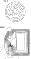
- One of the spring elements 6 is in Fig. 5 shown in plan view.
- the spring element 6 is formed substantially flat and has curved, here substantially S-shaped, struts 13, which provide for the radial alignment of the actuator 1.
- the radial stiffness of the spring element 6 is high in comparison to its axial rigidity, so that the radial alignment is ensured even with an axial movement.
- the actuator 1 comprises a magnet armature 3 and a carrier element 4, which is arranged between the armature 3 and the plunger 8.
- the plunger 8 is in a bore 9 (see Fig. 2a . 3 ) of the carrier element 4, but may also be formed with the carrier element 4 as an integral component.
- the plunger 8 serves to connect the linear actuator to surrounding components of the engine mount. Since the linear actuator does not have a fixed pole part, two permanent magnets 7 are provided radially on the outside so that a magnetic force is generated in the axial direction by generating an electromagnetic field through the coil 5 and the resulting magnetization of the magnet armature 3.
- the necessary magnetic force for displacement of the actuator 1 is effected by an interaction of the electromagnetically generated magnetic force and the magnetic force of the permanent magnet 7.
- the arrangement of the permanent magnet 7 in recesses of the magnet armature 3 also allows a compact design.
- the linear actuator is intended to influence by displacement of the plunger 8 other components of the engine mount so as to indirectly counteract vibrations of the engine of the motor vehicle, so that they are not transmitted to other body parts and in the interior of the vehicle.
- the linear actuator is excited dynamically with a frequency determined by a controller.
- the plunger is coupled to a membrane which limits an oil volume on which the engine is mounted and which is excited according to the vibration damping means of the linear actuator.
- the plunger 8 is inserted into the bore 9 of the support member 4 and projects through a central opening 14 of the spring elements. 6
- the mass of the actuator 1 is kept low, so that the resonant frequency of the actuator 1 is increased and inertia effects are reduced. Accordingly, the mass of the armature 3 are reduced to a minimum and the support member 4 made of a lightweight material, such as aluminum, magnesium, plastic or a fiber composite material, namely a material having a lower density than the material of the magnet armature 3.
- a lightweight material such as aluminum, magnesium, plastic or a fiber composite material
- the magnet armature 3 may have a radially inwardly tapering cross-sectional shape, as long as, as in Fig. 6 can be seen, the relevant field lines 15 extend substantially within the armature 3.
- Other cross-sectional shapes which satisfy this condition are also possible, for example rounded shapes.
- Fig. 2a the structure of the actuator 1 (without the plunger 8) is shown in section.
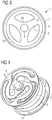
- Fig. 3 shows a plan view. It can be seen that the armature 3 is formed as an annular part of the actuator 1.
- the carrier element 4 is arranged radially inwardly with respect to the magnet armature 3.
- the support element 4 is here formed in two parts. In particular, by the beveled radially outer side of the support member 4 and the corresponding tapered shape of the armature 3 of the armature 3 can be easily held without additional fasteners.
- the weight of the support member 4 is further reduced by openings 12, and radial recesses 18 and axial recesses 17 are provided.
- the rim-like design of the support member 4 can be seen with its spoke-like webs 11, which connect a radially outer part 19 with a radially inner part 20.
- the radially outer part 19 carries the armature 3, while the radially inner part 20 carries the plunger 8.
- Other forms of the carrier element 4, in particular the perforations and recesses, are possible and can be selected depending on the load to be carried and the material used. It is also possible to provide no perforations and / or recesses.
- the armature 3 occupies only a small part of the actuator 1.
- the armature 3 may occupy less than 20%, preferably less than 10%, of the total diameter of the actuator 1.
- the magnet armature 3 may have an outer diameter of 47.4 mm and an inner diameter of 39.0 mm, so that the magnet armature 3 has a wall thickness of only 4.2 mm.
- the support member 4 ' is formed by two deep-drawn parts. There are two identical deep-drawn parts 4 'are provided, which face each other. Between the two parts of the armature 3 'is arranged, analogous to the two-part construction of in Fig. 2a illustrated carrier element. 4 In order to allow an exchange of fluid in the axial direction and also to further reduce weight, axial openings 12 'are provided. These are provided in both parts of the support member 4 ', wherein the parts of the support member 4' are aligned with each other so that the openings 12 'of the two parts coincide. Furthermore, the central bore 9 in the support member 4 ', in which the plunger 8 is supported, formed by deep drawing. The production of the carrier element 4 'in the deep drawing process is particularly simple and inexpensive.
Landscapes
- Engineering & Computer Science (AREA)
- Power Engineering (AREA)
- Physics & Mathematics (AREA)
- Electromagnetism (AREA)
- General Engineering & Computer Science (AREA)
- Mechanical Engineering (AREA)
- Chemical & Material Sciences (AREA)
- Combustion & Propulsion (AREA)
- Transportation (AREA)
- Arrangement Or Mounting Of Propulsion Units For Vehicles (AREA)
- Reciprocating, Oscillating Or Vibrating Motors (AREA)
- Vibration Prevention Devices (AREA)
Description
- Die vorliegende Erfindung betrifft einen Linearaktuator, insbesondere zur Verwendung in einem aktiven Motorlager eines Fahrzeugs.
- In Kraftfahrzeugen können zur Verbesserung des Komforts so genannte aktive Motorlager eingesetzt werden. Mittels eines aktiven Motorlagers können unerwünschte Schwingungen und eine dadurch verursachte Geräuschübertragung in den Innenraum des Fahrzeugs unterdrückt oder zumindest verringert werden. Unerwünschte Schwingungen können beispielsweise bei einer Zylinderabschaltung des Motors auftreten, wenn einer oder mehrere der Zylinder des Motors abgeschaltet werden, wobei der Motor unrund laufen kann. Ein aktives Motorlager weist dazu eine Steuerung für einen oder mehrere Aktuatoren auf, um den Schwingungen des Motors mittels der Aktuatoren in dem Fachmann geläufiger Weise entgegenzuwirken.
- Bei den Aktuatoren kann es sich insbesondere um Linearaktuatoren handeln, welche elektromagnetisch betrieben werden. Ein Linearaktuator weist üblicherweise einen Stator mit einer elektrisch bestrombaren Spule zur Erzeugung eines elektromagnetischen Feldes sowie ein bezüglich des Stators axial beweglich gelagertes Stellglied mit einem Magnetanker auf. Das Stellglied besitzt außerdem einen sich in axialer Richtung erstreckenden Stößel zur Betätigung des aktiven Motorlagers. Es ist vorteilhaft, das Stellglied beispielsweise mittels eines Federelements derart in dem Stator zu lagern, dass es reibungsfrei axial bewegbar ist.
-
EP 0 181 056 A zeigt eine Schaltmagnetanordnung, bei der Stellglied in einem zylinderförmigen Magentraum, der von einem Stator gebildet ist, axial beweglich gelagert ist, wobei das Stellglied ein Trägerelement aus Aluminium oder Plastik für einen Stößel aufweist und gegenüber dem Stößel axial an einen massiven den Magentraum radial ausfüllenden Magnetanker über ineinandergreifende komplementäre Kegelflächen angrenzt. -
EP0258568 zeigt ein elektromagnetisches Stellelement bestehend aus einer in einem hohlzylinderförmigen Permanentmagneten koaxial angeordneten Kombination aus Spulenkörper und Spulenwicklung. Der Spulenkörper ist an beiden Enden durch scheibenförmige Federn gelagert. Bei der Ansteuerung des Linearaktuators zur Schwingungsunterdrückung des Motors können hohe Frequenzen auftreten, mit denen das Stellglied bewegt wird. Aufgabe der vorliegenden Erfindung ist es, einen Linearaktuator, insbesondere für ein aktives Motorlager, bereitzustellen, der ein gutes Verhalten auch bei Schwingungen mit hoher Frequenz aufweist. - Die Aufgabe wird durch einen Linearaktuator mit den Merkmalen des unabhängigen Anspruchs gelöst. Weiterbildungen und vorteilhafte Ausgestaltungen sind in den abhängigen Ansprüchen angegeben.
- Erfindungsgemäß umfasst das Stellglied ein Trägerelement, welches sich in radialer Richtung zwischen dem Magnetanker und dem Stößel erstreckt. Das Trägerelement besteht aus einem nicht-magnetischen Material mit einer geringeren Dichte als der Magnetanker. Der Magnetanker reicht somit nicht bis an den Stößel heran, sondern wird von einem Trägerelement getragen, welches in vorteilhafter Leichtbauweise ausgebildet sein kann. Auf diese Weise kann das Gewicht des Stellglieds reduziert werden, was sich positiv auf das Verhalten des Linearaktuators auch bei Schwingungen mit hoher Frequenz auswirkt. Durch die reduzierte Massenträgheit des Stellglieds verbessert sich das Ansprechverhalten, da insbesondere bei einer Umkehrung der Bestromung der Spule die Umkehrspanne des Stellglieds verringert wird.
- Der Erfindung liegt die Erkenntnis zu Grunde, dass die räumliche Ausdehnung des Magnetankers, welcher aus einem verhältnismäßig, schweren magnetischen Material besteht, reduziert werden kann, ohne dass sich dies wesentlich auf die Magnetkraft auswirkt, die auf den Magnetanker wirkt. Daher kann der radial innen liegende Teil des Stellglieds durch ein nicht magnetisches, leichteres Material ersetzt werden. Denn es hat sich unerwarteterweise herausgestellt, dass in diesem Bereich nahezu keine Feldlinien des elektromagnetischen Feldes der Spule verlaufen. Das bedeutet, dass in diesem Bereich höchstens ein ungeordneter Streufluss des Magnetfeldes auftritt, der jedoch auf die Magnetkraft keinen Einfluss hat. Die relevanten Feldlinien verlaufen in einem geschlossenen Kreis im Eisenkreis des Linearaktuators, insbesondere durch den Magnetanker.
- Durch diese Aufteilung des Stellglieds in den magnetisch relevanten Magnetanker und den magnetisch nicht relevanten Träger wird somit eine Gewichtsminimierung bei gleichzeitig uneingeschränkter magnetischer Funktion erreicht. Besonders bei Aktuatoren, welche bei hohen Frequenzen betrieben oder angeregt werden, ist diese Eigenschaft sehr vorteilhaft, da dadurch die Resonanzfrequenz des Linearaktuators so hoch wie möglich liegt.
- Vorzugsweise sind der Magnetanker und das Trägerelement daher derart dimensioniert, dass eine Vergrößerung des Magnetankers in Radialrichtung nach innen keine Vergrößerung oder zumindest im Wesentlichen keine Vergrößerung, beispielsweise eine Vergrößerung um maximal 5%, der im Betrieb durch das elektromagnetische Feld erzeugten und auf das Stellglied wirkenden Magnetkraft bewirken würde. Mit anderen Worten, die räumliche Ausdehnung und die Masse des Magnetankers sind bei einem vorgegeben Aufbau des Stators und einer vorgegebenen Stromstärke, mit der die Spule bestromt wird, auf ein Minimum reduziert. Es ist nicht notwendig, den Magnetanker radial nach innen in Richtung des Stößels zu vergrößern und das Trägerelement dementsprechend zu verkleinern, da wie erläutert in diesem Bereich keine relevanten Feldlinien des elektromagnetischen Feldes verlaufen. Die relevanten Feldlinien verlaufen durch dem Magnetanker hindurch. Der Magnetanker ist somit auf sein magnetisch relevantes Volumen reduziert. Eine weitere Verkleinerung des Magnetankers würde jedoch zu einer Drosselung des Magnetfeldes und zu einer negativen Beeinflussung der Feldlinien führen, was eine Verkleinerung der Magnetkraft zur Folge hätte.
- In einer bevorzugten Ausgestaltung der Erfindung ist der Magnetanker ringförmig ausgebildet und umgibt das Trägerelement. Der Magnetanker nimmt somit denjenigen Teil des Stellglieds ein, welcher zu der Spule benachbart und daher für die Wirkung des Magnetfelds besonders relevant ist. Vorteilhafterweise ist der ringförmige Magnetanker dabei so schmal wie möglich ausgebildet, wobei das Verhältnis des Außendurchmessers des Magnetankers zum Innendurchmesser des Magnetankers höchstens 2:1, vorzugsweise höchstens 1,5:1 und weiter vorzugsweise höchstens 1,25:1 beträgt. Bezogen auf den Gesamtdurchmesser des Stellglieds nimmt der Magnetanker somit vorzugsweise höchstens die Hälfte, weiter vorzugsweise höchstens ein Drittel und noch weiter bevorzugt höchstens ein Fünftel ein.
Vorzugsweise verjüngt sich der Querschnitt des Magnetankers in axialer Richtung nach innen. Es hat sich nämlich gezeigt, dass auch die Form des Querschnitts des Magnetankers dazu genutzt werden kann, das Volumen des Magnetankers zu reduzieren, ohne dabei die Kraftbilanz der Magnetkraft negativ zu beeinflussen. Insbesondere kann der Querschnitt des Magnetankers von radial innen reduziert werden, wobei die Feldlinien des elektromagnetischen Feldes nicht gestört werden. Beispielsweise können im Vergleich zu einem rechteckigen Querschnitt eine Ecke oder zwei Ecken von radial innen weggenommen werden, so dass beispielsweise ein etwa trapezförmiger Querschnitt entsteht. Andere sich radial nach innen verjüngende Querschnittsformen sind ebenso möglich, wie beispielsweise eine Trapezform mit abgerundeten Ecken, eine runde Form oder auch eine konkave Form, solange der Verlauf der Feldlinien durch den Magnetanker dadurch nicht behindert wird. - Zur Reduzierung des Gewichts des Stellglieds ist es vorteilhaft, wenn das Trägerelement ein Leichtbaumaterial umfasst oder im Wesentlichen vollständig daraus besteht, wie beispielsweise Aluminium, Magnesium, Kunststoff und/oder einen Faserverbundwerkstoff.
- Das Stellglied umfasst zumindest einen Dauermagneten, der an den Magnetanker angrenzt und vorzugsweise am Außenumfang des Magnetankers angeordnet ist. In einer bevorzugten Ausgestaltung können zwei in axialer Richtung beabstandete und vorzugsweise in radialer Richtung magnetisierte Dauermagneten vorgesehen sein. Die Dauermagneten, welche auch als Permanentmagneten bezeichnet werden können, sind insbesondere dann von Bedeutung, wenn der Eisenkreis des Linearaktuators kein feststehendes Polteil umfasst oder eine von der Polarität des Erregerstroms abhängige Bewegungsrichtung des Stellglieds gewünscht ist. Die axiale Verlagerung des Stellglieds wird dann durch die auf den Magnetanker wirkende Magnetkraft des Magnetfelds hervorgerufen, welches sich aus dem elektromagnetischen Feld der bestromten Spule und dem Magnetfeld der Dauermagneten zusammensetzt.
- Vorteilhaft weist das Trägerelement Durchbrechungen auf und kann vorzugsweise in axialer Richtung zumindest bereichsweise eine geringere
- Abmessung aufweisen als der Magnetanker. Das Trägerelement kann auch Ausnehmungen aufweisen, um Gewicht zu sparen. Diese Maßnahmen dienen dazu, das Volumen und damit die Masse des Trägerelements weiter zu reduzieren. Das Ausmaß, die Anordnung, die Ausgestaltung und die Form der Durchbrechungen und/oder Ausnehmungen in dem Trägerelement sind insbesondere von dem verwendeten Material des Trägerelements und auch den von der Anwendung abhängenden Magnetkräften abhängig, und zwar derart, dass die mechanische Stabilität des Trägerelements nicht beeinträchtigt ist. Die Durchbrechungen können jegliche Form aufweisen und sich in axialer Richtung erstrecken. Es ist auch möglich, keine vollständig durch das Trägerelement hindurchtretenden Durchbrechungen vorzusehen, sondern lediglich Ausnehmungen auf einer oder beiden axialen Seiten des Trägerelements auszubilden. Das Trägerelement weist einen den Magnetanker tragenden radial außen liegenden Teil und einen den Stößel tragenden radial innen liegenden Teil auf, welche über speichenartige Stege miteinander verbunden sind. Beispielsweise kann das Trägerelement wie eine Felge ausgebildet sein und der Magnetanker auf dem Außenumfang des Trägerelements sitzen. Das Trägerelement kann zumindest ein tiefgezogenes Teil umfassen, was eine besonders einfache und kostengünstige Herstellung erlaubt.
Wie bereits eingangs erläutert, ist das Stellglied mittels zumindest eines Federelements in dem Stator derart gelagert, dass es bei Bestromung der Spule reibungsfrei axial bewegbar ist. Vorzugsweise ist das Stellglied an gegenüberliegenden axialen Seiten des Magnetankers jeweils über mindestens ein Federelement mit dem Stator derart gekoppelt, dass das Stellglied mittels der Federelemente bezüglich des Stators radial ausgerichtet ist. Bei dem mindestens einen Federelement zur radialen Ausrichtung handelt es sich vorteilhaft um dasselbe Federelement wie zur reibungsfreien Lagerung. Zusätzlich zur Lagerfunktion können die Federelemente definierte Rückstellkräfte auf das Stellglied ausüben, so dass durch geeignete Wahl der Federgeometrie und der Federdicke die Steifigkeit des Linearaktuators eingestellt werden kann, ohne dass beispielsweise zusätzliche Druckfedern notwendig sind. Vorzugsweise werden Federelemente verwendet, die im entspannten Zustand eben sind und sich in einer Ebene senkrecht zur Bewegungsrichtung des Magnetankers erstrecken. Die Federelemente können aus einem blechförmigen Material herausgetrennt, vorzugsweise ausgestanzt, sein und somit als werkzeugfallendes Teil, beispielsweise als Schnittteil, einfach und kostengünstig hergestellt werden. Die Herstellung durch Laserschnitt oder durch Ätzen ist ebenfalls möglich. - Die reibungsfreie Lagerung des Stellglieds hat den Vorteil, dass keine Reibungskräfte auftreten und dadurch eine mechanische Belastung des Stellglieds vermieden wird. Ferner wird keine Hysterese durch Reibung erzeugt, so dass lediglich eine magnetische Hysterese verbleibt. Durch die fehlende Reibung wird das Ansprechverhalten des Linearaktuators verbessert, d.h. bei einer Änderung des Führungssignals, insbesondere einer Umkehr des elektrischen Stroms, erfolgt unverzögert eine Änderung des Stellsignals, d.h. der erzeugten Kraft bzw. des von dem Stellglied zurückgelegten Wegs. In Kennlinien ist dieses Verhalten durch eine spitze Umkehr des Ausgangssignals bei Umkehr des Führungssignals zu erkennen. Totzeiten an den Umkehrpunkten werden so vermieden.
- Der Linearaktuator wird vorzugsweise in einem Motorlager für einen Motor eines Fahrzeugs verwendet, um Schwingungen des Motorlagers entgegenzuwirken. Dazu ist eine Steuerung für den Linearaktuator vorgesehen, die den Linearaktuator auf geeignete Weise steuert. Insbesondere lässt sich damit die Schwingungsübertragung von dem Motor auf die Karosserie des Fahrzeugs, welche beispielsweise bei einer Zylinderabschaltung des Motors auftreten kann, reduzieren. Das Motorlager kann ein mit Öl gefülltes Volumen umfassen, auf dem der Motor gelagert ist. Der Stößel des Linearaktuators ist an eine an das Ölvolumen angrenzende Membran gekoppelt, so dass das Ölvolumen mit einer von einem Sensor aufgenommenen Frequenz angeregt werden kann, um die Schwingungen des Motors durch die entsprechenden Schwingungen des Ölvolumens zu dämpfen.
- Im Folgenden wird die Erfindung anhand der begleitenden schematischen Zeichnungen beispielhaft beschrieben. Darin zeigen:
-
Fig. 1 einen Linearaktuator in einer Schnittdarstellung, -
Fig. 2a das Stellglied des Linearaktuators ausFig. 1 ohne den Stößel in einer Schnittdarstellung, -
Fig. 2b ein anderes Ausführungsbeispiel eines Stellglieds (ohne Stößel), -
Fig. 3 das Stellglied des Linearaktuators ausFig. 1 ohne den Stößel in Draufsicht, -
Fig. 4 das Stellglied des Linearaktuators ausFig. 1 zusammen mit den Federelementen in perspektivischer Darstellung, -
Fig. 5 ein Federelement in Draufsicht und -
Fig. 6 schematisch den Verlauf der Feldlinien des elektromagnetischen Felds. - In
Fig. 1 ist ein Linearaktuator für ein aktives Motorlager eines Kraftfahrzeugs dargestellt. Der Linearaktuator weist einen ortsfesten Stator 2 auf, der eine elektrisch bestrombare Spule 5 umfasst. Des Weiteren ist ein elektrischer Anschluss 10 vorgesehen, über den der Linearaktuator mit Strom versorgt wird. In dem Stator 2 ist ein Stellglied 1 mit einem Stößel 8 über zwei Federelemente 6 axial beweglich und radial ausgerichtet gelagert. Die Federelemente 6 sind derart ausgebildet, dass das Stellglied 1 reibungsfrei gelagert ist. D.h. zwischen dem Stator 2 und dem Stellglied 1 besteht vorzugsweise ein Luftspalt, der durch die Lagerung des Stellglieds 1 mittels der Federelemente 6 auch während der axialen Bewegung des Stellglieds 1 aufrecht erhalten wird. Eines der Federelemente 6 ist inFig. 5 in Draufsicht dargestellt. Das Federelement 6 ist im Wesentlichen eben ausgebildet und weist geschwungene, hier im Wesentlichen S-förmige, Federbeine 13 auf, die für die radiale Ausrichtung des Stellglieds 1 sorgen. Die radiale Steifigkeit des Federelements 6 ist im Vergleich zu seiner axialen Steifigkeit hoch, so dass die radiale Ausrichtung auch bei einer axialen Bewegung gewährleistet ist. Durch die Verwendung solcher Federelemente 6 kann auf zusätzliche Druckfedern zur Rückstellung des Stellglieds 1 verzichtet werden, da die Federelemente 6 nicht nur zur Lagerung sondern auch zur Rückstellung des Stellglieds 1 in seine Ausgangsposition dienen. - Das Stellglied 1 umfasst einen Magnetanker 3 sowie ein Trägerelement 4, welches zwischen dem Magnetanker 3 und dem Stößel 8 angeordnet ist. Der Stößel 8 ist in eine Bohrung 9 (siehe
Fig. 2a ,3 ) des Trägerelements 4 eingesetzt, kann aber auch mit dem Trägerelement 4 als integrales Bauteil ausgebildet sein. Durch Bestromung der Spule 5 wird das Stellglied 1 entgegen der axial wirkenden Kräfte der Federelemente 6 in axialer Richtung verlagert. Der Stößel 8 dient dabei zur Anbindung des Linearaktuators an umliegende Bauteile des Motorlagers. Da der Linearaktuator kein festes Polteil aufweist, sind radial außen liegend zwei Dauermagnete 7 vorgesehen, so dass durch Erzeugung eines elektromagnetischen Feldes durch die Spule 5 und die daraus resultierende Magnetisierung des Magnetankers 3 eine Magnetkraft in axialer Richtung erzeugt wird. Die notwendige Magnetkraft zur Verlagerung des Stellglieds 1 wird durch ein Zusammenspiel der elektromagnetisch erzeugten Magnetkraft und der Magnetkraft der Dauermagneten 7 bewirkt. Die Anordnung der Dauermagneten 7 in Ausnehmungen des Magnetankers 3 erlaubt zudem eine kompakte Bauweise. - Der Linearaktuator ist dazu vorgesehen, durch Verlagerung des Stößels 8 andere Bauteile des Motorlagers so zu beeinflussen, um mittelbar Schwingungen des Motors des Kraftfahrzeugs entgegenzuwirken, damit diese nicht auf andere Karosserieteile und in den Innenraum des Fahrzeugs übertragen werden. Dazu wird der Linearaktuator mit einer durch eine Steuerung ermittelten Frequenz dynamisch angeregt. Beispielsweise ist der Stößel an eine Membran gekoppelt, welche ein Ölvolumen begrenzt, auf dem der Motor gelagert ist und das zur Schwingungsdämpfung entsprechend mittels des Linearaktuators angeregt wird. Durch Umpolung der Spule 5 erfolgt eine Umkehrung der Magnetkraft und damit eine Umkehrung der Bewegungsrichtung des Stellglieds 1. Zusätzlich wird eine Bewegungsumkehrung durch die Rückstellkraft der Federelemente 6 unterstützt. In
Fig. 4 ist die Anordnung des Stellglieds 1 mit den Federelementen 6 dargestellt. Es können auch mehr als zwei oder nur ein derartiges Federelement vorgesehen sein. Der Stößel 8 ist in die Bohrung 9 des Trägerelements 4 eingesetzt und ragt durch eine zentrale Öffnung 14 der Federelemente 6.
Bei der Anwendung des Linearaktuators in einem aktiven Motorlager treten hohe Frequenzen auf, mit denen der Linearaktuator schwingt. Durch die erfindungsgemäße Lösung wird die Masse des Stellglieds 1 gering gehalten, so dass die Resonanzfrequenz des Stellglieds 1 erhöht wird und Massenträgheitseffekte reduziert werden. Dementsprechend sind die Masse des Magnetankers 3 auf ein Minimum reduziert und das Trägerelement 4 aus einem Leichtbaumaterial, wie Aluminium, Magnesium, Kunststoff oder einem Faserverbundwerkstoff, nämlich einem Material mit einer geringeren Dichte als das Material des Magnetankers 3 gefertigt.
Wie inFig. 6 dargestellt, treten im radial innen liegenden Bereich nahezu keine relevanten Feldlinien des elektromagnetischen Feldes auf, so dass dieser Bereich für die Kraftbilanz nicht relevant ist. Lediglich ein für die Kraftbilanz nicht relevanter, ungeordneter Streufluss 16 tritt aus dem Eisenkreis aus. Es ist ausreichend, den Magnetanker 3 nur in dem für die Kraftbilanz relevanten Bereich, d.h. in demjenigen Bereich des Stellglieds 1 vorzusehen, welcher von den relevanten Feldlinien 15 durchdrungen wird. Eine Vergrößerung des Magnetankers 3 nach radial innen liefert keinen oder im Wesentlichen keinen, beispielsweise maximal 5%, Kraftzuwachs bei vorgegebenen Aufbau des Stators 2 und bei vorgegebener Stromstärke. Daher kann hier das schwere magnetische Material des Magnetankers 3 durch ein nicht-magnetisches Leichtbaumaterial des Trägerelements 4 ersetzt werden. Der Magnetanker 3 kann eine sich nach radial innen verjüngende Querschnittsform aufweisen, solange, wie inFig. 6 zu sehen ist, die relevanten Feldlinien 15 im Wesentlichen innerhalb des Magnetankers 3 verlaufen. Andere Querschnittsformen, die diese Bedingung erfüllen, sind ebenfalls möglich, beispielsweise abgerundete Formen. - In
Fig. 2a ist der Aufbau des Stellglieds 1 (ohne den Stößel 8) im Schnitt dargestellt.Fig. 3 zeigt eine Draufsicht. Es ist zu erkennen, dass der Magnetanker 3 als ringförmiger Teil des Stellglieds 1 ausgebildet ist. Das Trägerelement 4 ist bezüglich des Magnetankers 3 radial innen liegend angeordnet. Aus Konstruktionsgründen ist das Trägerelement 4 hier zweiteilig ausgebildet. Insbesondere kann durch die abgeschrägte radial außen liegende Seite des Trägerelements 4 und die entsprechend abgeschrägte Form des Magnetankers 3 der Magnetanker 3 einfach ohne zusätzliche Befestigungsmittel gehalten werden. - Wie in
Fig. 2a und3 dargestellt, ist das Gewicht des Trägerelements 4 weiter reduziert, indem Durchbrechungen 12, sowie radiale Ausnehmungen 18 und axiale Ausnehmungen 17 vorgesehen sind. In der Draufsicht ist das felgenartige Design des Trägerelements 4 mit seinen speichenartigen Stegen 11 zu erkennen, welche einen radial außen liegenden Teil 19 mit einem radial innen liegenden Teil 20 verbinden. Der radial außen liegende Teil 19 trägt den Magnetanker 3, während der radial innen liegende Teil 20 den Stößel 8 trägt. Andere Formen des Trägerelements 4, insbesondere der Durchbrechungen und Ausnehmungen, sind möglich und können abhängig von der zu tragenden Belastung und dem verwendeten Material gewählt werden. Es ist auch möglich, keine Durchbrechungen und/oder Ausnehmungen vorzusehen. Der Magnetanker 3 nimmt nur einen kleinen Teil des Stellglieds 1 ein. Beispielsweise kann der Magnetanker 3 weniger als 20%, vorzugsweise weniger als 10%, des Gesamtdurchmessers des Stellglieds 1 einnehmen. Beispielsweise kann der Magnetanker 3 einen Außendurchmesser von 47,4 mm und einen Innendurchmesser von 39,0 mm aufweisen, so dass der Magnetanker 3 eine Wandstärke von lediglich 4,2 mm aufweist. - In einem alternativen Ausführungsbeispiel, das in
Fig. 2b dargestellt ist und für das ansonsten das zuvor Gesagte ebenso gilt, ist das Trägerelement 4' durch zwei tiefgezogene Teile gebildet. Es sind zwei identische tiefgezogene Teile 4' vorgesehen, die einander zugewandt sind. Zwischen den beiden Teilen ist der Magnetanker 3' angeordnet, analog der zweiteiligen Konstruktion des inFig. 2a dargestellten Trägerelements 4. Um einen Austausch von Fluid in axialer Richtung zu ermöglichen und auch um weiter an Gewicht zu sparen, sind axiale Durchbrechungen 12' vorgesehen. Diese sind in beiden Teilen des Trägerelements 4' vorgesehen, wobei die Teile des Trägerelements 4' derart zueinander ausgerichtet sind, dass sich die Durchbrechungen 12' der beiden Teile decken. Ferner ist auch die zentrale Bohrung 9 in dem Trägerelement 4', in welcher der Stößel 8 getragen wird, durch Tiefziehen gebildet. Die Herstellung des Trägerelements 4' im Tiefziehverfahren ist besonders einfach und kostengünstig.
Claims (14)
- Linearaktuator, umfassend einen Stator (2) mit einer elektrisch bestrombaren Spule (5) zur Erzeugung eines elektromagnetischen Feldes (15) sowie ein bezüglich des Stators (2) axial beweglich gelagertes Stellglied (1) mit einem magnetischen Magnetanker (3) und zumindest einem an dem Magnetanker (3) angrenzenden Dauermagneten (7), und einem sich in axialer Richtung erstreckenden Stößel (8), wobei das Stellglied (1) mittels zumindest eines Federelements (6) in dem Stator (2) derart gelagert ist, dass es bei Bestromung der Spule (5) reibungsfrei axial bewegbar ist,
dadurch gekennzeichnet, dass das Stellglied (1) ein Trägerelement (4) umfasst, welches sich in radialer Richtung zwischen dem Magnetanker (3) und dem Stößel (8) erstreckt, wobei das Trägerelement (4) aus einem nicht-magnetischen Material mit einer geringeren Dichte als der Magnetanker (3) besteht, wobei das Trägerelement (4) einen den Magnetanker (3) tragenden, radial außen liegenden Teil (19) und einen den Stößel (8) tragenden, radial innen liegenden Teil (20) aufweist, welche über speichenartige Stege (11) miteinander verbunden sind. - Linearaktuator nach Anspruch 1, wobei der Magnetanker (3) und das Trägerelement (4) derart dimensioniert und eingerichtet sind, dass eine Vergrößerung des Magnetankers (3) in radialer Richtung nach innen im Wesentlichen keine Vergrößerung der im Betrieb durch das elektromagnetische Feld (15) erzeugten und auf das Stellglied (1) wirkenden Magnetkraft bewirken würde.
- Linearaktuator nach Anspruch 1 oder 2, wobei der Magnetanker (3) ringförmig ausgebildet ist und das Trägerelement (4) umgibt.
- Linearaktuator nach Anspruch 3, wobei das Verhältnis des Außendurchmessers des Magnetankers (3) zum Innendurchmesser des Magnetankers (3) höchstens 2:1, vorzugsweise höchstens 1,5:1, weiter vorzugsweise höchstens 1,25:1, beträgt.
- Linearaktuator nach einem der Ansprüche 1 bis 4, wobei sich der Querschnitt des Magnetankers (3) in radialer Richtung nach innen verjüngt.
- Linearaktuator nach einem der Ansprüche 1 bis 5, wobei das Trägerelement (4) Aluminium, Magnesium, Kunststoff und/oder einen Faserverbundwerkstoff umfasst oder im Wesentlichen vollständig daraus besteht.
- Linearaktuator nach einem der Ansprüche 1 bis 6, wobei der zumindest eine Dauermagnet (7) am Außenumfang des Magnetankers angeordnet ist, wobei vorzugsweise zwei in axialer Richtung beabstandete Dauermagneten (7) vorgesehen sind.
- Linearaktuator nach einem der Ansprüche 1 bis 7, wobei das Trägerelement (4) Durchbrechungen (12) aufweist und vorzugsweise in axialer Richtung zumindest bereichsweise (17) eine geringere Abmessung aufweist als der Magnetanker (3).
- Linearaktuator nach einem der Ansprüche 1 bis 8, wobei das Trägerelement (4) zumindest ein tiefgezogenes Teil umfasst.
- Linearaktuator nach einem der Ansprüche 1 bis 9, wobei das Stellglied (1) an gegenüberliegenden axialen Seiten des Magnetankers jeweils über mindestens ein Federelement (6) mit dem Stator (2) derart gekoppelt ist, dass das Stellglied (1) mittels der Federelemente (6) bezüglich des Stators (2) radial ausgerichtet ist.
- Linearaktuator nach Anspruch 10, wobei die Federelemente (6) im entspannten Zustand eben sind und sich in einer Ebene senkrecht zur Bewegungsrichtung des Stellglieds (4) erstrecken.
- Linearaktuator nach Anspruch 10 oder 11, wobei die Federelemente (6) aus einem blechförmigen Material herausgetrennt, vorzugsweise ausgestanzt, sind.
- Motorlager für einen Motor eines Fahrzeugs, umfassend zumindest einen Linearaktuator nach einem der Ansprüche 1 bis 12 und eine Steuerung für den Linearaktuator, wobei die Steuerung eingerichtet ist, Schwingungen des Motorlagers durch geeignete Steuerung des Linearaktuators entgegenzuwirken.
- Verwendung des Linearaktuators nach einem der Ansprüche 1 bis 12 in einem Motorlager für einen Motor eines Fahrzeugs.
Applications Claiming Priority (2)
| Application Number | Priority Date | Filing Date | Title |
|---|---|---|---|
| DE102013202166.6A DE102013202166A1 (de) | 2013-02-11 | 2013-02-11 | Linearaktuator |
| PCT/EP2014/052566 WO2014122312A1 (de) | 2013-02-11 | 2014-02-10 | Linearaktuator |
Publications (2)
| Publication Number | Publication Date |
|---|---|
| EP2954541A1 EP2954541A1 (de) | 2015-12-16 |
| EP2954541B1 true EP2954541B1 (de) | 2018-11-21 |
Family
ID=50070592
Family Applications (1)
| Application Number | Title | Priority Date | Filing Date |
|---|---|---|---|
| EP14703403.7A Not-in-force EP2954541B1 (de) | 2013-02-11 | 2014-02-10 | Linearaktuator |
Country Status (4)
| Country | Link |
|---|---|
| US (1) | US10284068B2 (de) |
| EP (1) | EP2954541B1 (de) |
| DE (1) | DE102013202166A1 (de) |
| WO (1) | WO2014122312A1 (de) |
Families Citing this family (8)
| Publication number | Priority date | Publication date | Assignee | Title |
|---|---|---|---|---|
| DE102016203064A1 (de) | 2016-02-26 | 2017-08-31 | Robert Bosch Gmbh | Elektromagnetisches Lager mit einstellbarer Steifigkeit |
| US20180068459A1 (en) * | 2016-09-08 | 2018-03-08 | Ford Global Technologies, Llc | Object Distance Estimation Using Data From A Single Camera |
| WO2018142801A1 (ja) * | 2017-01-31 | 2018-08-09 | 住友理工株式会社 | 能動型制振装置 |
| DE102017103027A1 (de) * | 2017-02-15 | 2018-08-16 | Rausch & Pausch Gmbh | Linearaktuator |
| DE102017120627A1 (de) | 2017-09-07 | 2019-03-07 | Rausch & Pausch Gmbh | Verfahren zur Herstellung eines Magnetanker-Stößel-Verbundes und Magnetanker-Stößel-Verbund für einen Linearaktuator |
| US11643169B2 (en) * | 2019-02-19 | 2023-05-09 | The Government of the USA represented by the Sec. of the Navy | Apparatus with a controllable surface for underwater boundary flow |
| DE102019112334A1 (de) * | 2019-05-10 | 2020-11-12 | Eto Magnetic Gmbh | Aktorvorrichtung zur aktiven Schwingungsreduzierung, -dämpfung und/oder -tilgung |
| DE102020202062A1 (de) | 2020-02-19 | 2021-08-19 | Robert Bosch Gesellschaft mit beschränkter Haftung | Stator für eine elektrische Rotationsmaschine |
Citations (1)
| Publication number | Priority date | Publication date | Assignee | Title |
|---|---|---|---|---|
| EP0258569A2 (de) * | 1986-08-02 | 1988-03-09 | BBC Brown Boveri AG | Elektromagnetisches Stellelement |
Family Cites Families (16)
| Publication number | Priority date | Publication date | Assignee | Title |
|---|---|---|---|---|
| US2435817A (en) * | 1944-09-30 | 1948-02-10 | Gen Electric | Electromagnet with plunger |
| US4438419A (en) * | 1982-07-28 | 1984-03-20 | International Business Machines Corporation | Serial ring actuator |
| US4651118A (en) * | 1984-11-07 | 1987-03-17 | Zeuner Kenneth W | Proportional solenoid |
| JPH1189147A (ja) * | 1997-09-11 | 1999-03-30 | Meidensha Corp | アキシャル型モータ |
| US6509661B1 (en) * | 1999-01-14 | 2003-01-21 | Asmo Co., Ltd. | Motor and actuator |
| JP2002106633A (ja) * | 2000-09-28 | 2002-04-10 | Tokai Rubber Ind Ltd | 防振用アクチュエータおよびそれを用いた能動型防振装置 |
| JP2002195342A (ja) * | 2000-12-28 | 2002-07-10 | Tokai Rubber Ind Ltd | 流体封入式能動型防振装置およびその製造方法 |
| EP1649574A2 (de) * | 2003-07-10 | 2006-04-26 | Magnetic Applications Inc. | Kompakter hochleistungs-stromgenerator |
| DE102005011629A1 (de) * | 2005-03-09 | 2006-09-21 | Rausch & Pausch Gmbh | Elektromagnetischer Antrieb für Ventilsteuerungen |
| WO2007034195A1 (en) * | 2005-09-21 | 2007-03-29 | Ricardo Uk Ltd. | Linear actuator |
| JP4072696B2 (ja) * | 2005-12-21 | 2008-04-09 | 東海ゴム工業株式会社 | 流体封入式能動型防振装置 |
| US8047513B2 (en) * | 2007-09-21 | 2011-11-01 | Tokai Rubber Industries, Ltd. | Fluid filled type vibration damping device |
| KR101580688B1 (ko) * | 2008-11-24 | 2015-12-28 | 삼성전자주식회사 | 휴대용 단말기의 진동 모터 |
| JP2011094750A (ja) * | 2009-10-30 | 2011-05-12 | Tokai Rubber Ind Ltd | 流体封入式能動型エンジンマウント |
| CN102753855B (zh) * | 2009-12-09 | 2014-07-09 | 东海橡塑工业株式会社 | 电磁式驱动器及使用该电磁式驱动器的流体封入式有源型隔振装置 |
| US8919748B2 (en) | 2010-01-28 | 2014-12-30 | Keihin Corporation | Active antivibration device and manufacturing method for the same |
-
2013
- 2013-02-11 DE DE102013202166.6A patent/DE102013202166A1/de not_active Withdrawn
-
2014
- 2014-02-10 WO PCT/EP2014/052566 patent/WO2014122312A1/de not_active Ceased
- 2014-02-10 EP EP14703403.7A patent/EP2954541B1/de not_active Not-in-force
- 2014-02-10 US US14/766,606 patent/US10284068B2/en active Active
Patent Citations (1)
| Publication number | Priority date | Publication date | Assignee | Title |
|---|---|---|---|---|
| EP0258569A2 (de) * | 1986-08-02 | 1988-03-09 | BBC Brown Boveri AG | Elektromagnetisches Stellelement |
Also Published As
| Publication number | Publication date |
|---|---|
| EP2954541A1 (de) | 2015-12-16 |
| WO2014122312A1 (de) | 2014-08-14 |
| US20160006333A1 (en) | 2016-01-07 |
| US10284068B2 (en) | 2019-05-07 |
| DE102013202166A1 (de) | 2014-08-28 |
Similar Documents
| Publication | Publication Date | Title |
|---|---|---|
| EP2954541B1 (de) | Linearaktuator | |
| EP3061104B1 (de) | Elektromechanischer aktor | |
| EP3095119B1 (de) | Elektromagnetischer und dynamischer aktuator für aktive aggregatlager | |
| DE112015004653B4 (de) | Elektromagnetischer Schwingungsdämpfungsbetätiger, fluidgefüllte aktive Schwingungsdämpfungsvorrichtung und diese verwendende aktive Schwingungsregelvorrichtung | |
| EP3158629B1 (de) | Linearaktor, hydrolager sowie kraftfahrzeug mit einem derartigen hydrolager bzw. linearaktor | |
| DE102009049009B4 (de) | Aktuator für eine Verbrennungskraftmaschine | |
| DE102005053244A1 (de) | Aktive Schwingungsdämpfungsvorrichtung | |
| DE10347452A1 (de) | Aktuator, Verfahren zur Herstellung des Aktuators und Leistungsschalter, der mit dem Aktuator ausgestattet ist | |
| EP3364532B1 (de) | Linearaktuator | |
| EP3966840B1 (de) | Aktorvorrichtung zur aktiven schwingungsreduzierung, -dämpfung und/oder -tilgung | |
| DE10041807A1 (de) | Oszillationskraftgenerator und Vibrationsdämpfer, der den Generator verwendet | |
| WO2016037876A1 (de) | Elektromagnetische stellvorrichtung | |
| EP3158220B1 (de) | Hydrolager sowie kraftfahrzeug mit einem derartigen hydrolager | |
| EP3451510A1 (de) | Elektromagnetischer linearaktor | |
| EP3488107B1 (de) | Oszillierende verdrängerpumpe mit elektro-dynamischem antrieb und verfahren zu deren betrieb | |
| EP0541902B1 (de) | Gummilager | |
| DE112005002789B4 (de) | Stellantrieb | |
| EP3454349B1 (de) | Verfahren zur herstellung eines magnetanker-stössel-verbundes und magnetanker-stössel-verbund für einen linearaktuator | |
| EP3258131B1 (de) | Hydrolager | |
| DE19900788B4 (de) | Antriebsvorrichtung | |
| WO2018149694A1 (de) | Elektromagnetischer linearaktuator | |
| DE102021124654B4 (de) | Elektromagnetischer Hub- und/oder Haft-Aktor | |
| EP3839988B1 (de) | Stellvorrichtung | |
| DE102016203063A1 (de) | Reluktanzaktor für aktive Lager mit vermindertem Strombedarf | |
| DE102005001221A1 (de) | Elektromagnetischer Antrieb mit einem Permanentmagnete aufweisenden Läufer mit zusätzlichem Federelement |
Legal Events
| Date | Code | Title | Description |
|---|---|---|---|
| PUAI | Public reference made under article 153(3) epc to a published international application that has entered the european phase |
Free format text: ORIGINAL CODE: 0009012 |
|
| 17P | Request for examination filed |
Effective date: 20150806 |
|
| AK | Designated contracting states |
Kind code of ref document: A1 Designated state(s): AL AT BE BG CH CY CZ DE DK EE ES FI FR GB GR HR HU IE IS IT LI LT LU LV MC MK MT NL NO PL PT RO RS SE SI SK SM TR |
|
| AX | Request for extension of the european patent |
Extension state: BA ME |
|
| RIN1 | Information on inventor provided before grant (corrected) |
Inventor name: KEMNITZ, ROCCO Inventor name: DOEHLA, WERNER Inventor name: HAAS, JAKOB Inventor name: HUDEC, JULIUS |
|
| DAX | Request for extension of the european patent (deleted) | ||
| REG | Reference to a national code |
Ref country code: DE Ref legal event code: R079 Ref document number: 502014010139 Country of ref document: DE Free format text: PREVIOUS MAIN CLASS: H01F0007080000 Ipc: H01F0007160000 |
|
| GRAP | Despatch of communication of intention to grant a patent |
Free format text: ORIGINAL CODE: EPIDOSNIGR1 |
|
| STAA | Information on the status of an ep patent application or granted ep patent |
Free format text: STATUS: GRANT OF PATENT IS INTENDED |
|
| RIC1 | Information provided on ipc code assigned before grant |
Ipc: H02K 1/30 20060101ALI20180507BHEP Ipc: H01F 7/16 20060101AFI20180507BHEP Ipc: F16C 32/04 20060101ALI20180507BHEP Ipc: H02K 33/16 20060101ALI20180507BHEP |
|
| INTG | Intention to grant announced |
Effective date: 20180605 |
|
| GRAS | Grant fee paid |
Free format text: ORIGINAL CODE: EPIDOSNIGR3 |
|
| GRAA | (expected) grant |
Free format text: ORIGINAL CODE: 0009210 |
|
| STAA | Information on the status of an ep patent application or granted ep patent |
Free format text: STATUS: THE PATENT HAS BEEN GRANTED |
|
| AK | Designated contracting states |
Kind code of ref document: B1 Designated state(s): AL AT BE BG CH CY CZ DE DK EE ES FI FR GB GR HR HU IE IS IT LI LT LU LV MC MK MT NL NO PL PT RO RS SE SI SK SM TR |
|
| REG | Reference to a national code |
Ref country code: CH Ref legal event code: EP |
|
| REG | Reference to a national code |
Ref country code: IE Ref legal event code: FG4D Free format text: LANGUAGE OF EP DOCUMENT: GERMAN |
|
| REG | Reference to a national code |
Ref country code: AT Ref legal event code: REF Ref document number: 1068494 Country of ref document: AT Kind code of ref document: T Effective date: 20181215 |
|
| REG | Reference to a national code |
Ref country code: DE Ref legal event code: R096 Ref document number: 502014010139 Country of ref document: DE |
|
| REG | Reference to a national code |
Ref country code: NL Ref legal event code: MP Effective date: 20181121 |
|
| PG25 | Lapsed in a contracting state [announced via postgrant information from national office to epo] |
Ref country code: FI Free format text: LAPSE BECAUSE OF FAILURE TO SUBMIT A TRANSLATION OF THE DESCRIPTION OR TO PAY THE FEE WITHIN THE PRESCRIBED TIME-LIMIT Effective date: 20181121 Ref country code: LT Free format text: LAPSE BECAUSE OF FAILURE TO SUBMIT A TRANSLATION OF THE DESCRIPTION OR TO PAY THE FEE WITHIN THE PRESCRIBED TIME-LIMIT Effective date: 20181121 Ref country code: BG Free format text: LAPSE BECAUSE OF FAILURE TO SUBMIT A TRANSLATION OF THE DESCRIPTION OR TO PAY THE FEE WITHIN THE PRESCRIBED TIME-LIMIT Effective date: 20190221 Ref country code: NO Free format text: LAPSE BECAUSE OF FAILURE TO SUBMIT A TRANSLATION OF THE DESCRIPTION OR TO PAY THE FEE WITHIN THE PRESCRIBED TIME-LIMIT Effective date: 20190221 Ref country code: IS Free format text: LAPSE BECAUSE OF FAILURE TO SUBMIT A TRANSLATION OF THE DESCRIPTION OR TO PAY THE FEE WITHIN THE PRESCRIBED TIME-LIMIT Effective date: 20190321 Ref country code: ES Free format text: LAPSE BECAUSE OF FAILURE TO SUBMIT A TRANSLATION OF THE DESCRIPTION OR TO PAY THE FEE WITHIN THE PRESCRIBED TIME-LIMIT Effective date: 20181121 Ref country code: HR Free format text: LAPSE BECAUSE OF FAILURE TO SUBMIT A TRANSLATION OF THE DESCRIPTION OR TO PAY THE FEE WITHIN THE PRESCRIBED TIME-LIMIT Effective date: 20181121 Ref country code: LV Free format text: LAPSE BECAUSE OF FAILURE TO SUBMIT A TRANSLATION OF THE DESCRIPTION OR TO PAY THE FEE WITHIN THE PRESCRIBED TIME-LIMIT Effective date: 20181121 |
|
| PG25 | Lapsed in a contracting state [announced via postgrant information from national office to epo] |
Ref country code: AL Free format text: LAPSE BECAUSE OF FAILURE TO SUBMIT A TRANSLATION OF THE DESCRIPTION OR TO PAY THE FEE WITHIN THE PRESCRIBED TIME-LIMIT Effective date: 20181121 Ref country code: SE Free format text: LAPSE BECAUSE OF FAILURE TO SUBMIT A TRANSLATION OF THE DESCRIPTION OR TO PAY THE FEE WITHIN THE PRESCRIBED TIME-LIMIT Effective date: 20181121 Ref country code: NL Free format text: LAPSE BECAUSE OF FAILURE TO SUBMIT A TRANSLATION OF THE DESCRIPTION OR TO PAY THE FEE WITHIN THE PRESCRIBED TIME-LIMIT Effective date: 20181121 Ref country code: RS Free format text: LAPSE BECAUSE OF FAILURE TO SUBMIT A TRANSLATION OF THE DESCRIPTION OR TO PAY THE FEE WITHIN THE PRESCRIBED TIME-LIMIT Effective date: 20181121 Ref country code: PT Free format text: LAPSE BECAUSE OF FAILURE TO SUBMIT A TRANSLATION OF THE DESCRIPTION OR TO PAY THE FEE WITHIN THE PRESCRIBED TIME-LIMIT Effective date: 20190321 Ref country code: GR Free format text: LAPSE BECAUSE OF FAILURE TO SUBMIT A TRANSLATION OF THE DESCRIPTION OR TO PAY THE FEE WITHIN THE PRESCRIBED TIME-LIMIT Effective date: 20190222 |
|
| PG25 | Lapsed in a contracting state [announced via postgrant information from national office to epo] |
Ref country code: IT Free format text: LAPSE BECAUSE OF FAILURE TO SUBMIT A TRANSLATION OF THE DESCRIPTION OR TO PAY THE FEE WITHIN THE PRESCRIBED TIME-LIMIT Effective date: 20181121 Ref country code: PL Free format text: LAPSE BECAUSE OF FAILURE TO SUBMIT A TRANSLATION OF THE DESCRIPTION OR TO PAY THE FEE WITHIN THE PRESCRIBED TIME-LIMIT Effective date: 20181121 Ref country code: DK Free format text: LAPSE BECAUSE OF FAILURE TO SUBMIT A TRANSLATION OF THE DESCRIPTION OR TO PAY THE FEE WITHIN THE PRESCRIBED TIME-LIMIT Effective date: 20181121 Ref country code: CZ Free format text: LAPSE BECAUSE OF FAILURE TO SUBMIT A TRANSLATION OF THE DESCRIPTION OR TO PAY THE FEE WITHIN THE PRESCRIBED TIME-LIMIT Effective date: 20181121 |
|
| REG | Reference to a national code |
Ref country code: DE Ref legal event code: R097 Ref document number: 502014010139 Country of ref document: DE |
|
| PG25 | Lapsed in a contracting state [announced via postgrant information from national office to epo] |
Ref country code: EE Free format text: LAPSE BECAUSE OF FAILURE TO SUBMIT A TRANSLATION OF THE DESCRIPTION OR TO PAY THE FEE WITHIN THE PRESCRIBED TIME-LIMIT Effective date: 20181121 Ref country code: RO Free format text: LAPSE BECAUSE OF FAILURE TO SUBMIT A TRANSLATION OF THE DESCRIPTION OR TO PAY THE FEE WITHIN THE PRESCRIBED TIME-LIMIT Effective date: 20181121 Ref country code: SK Free format text: LAPSE BECAUSE OF FAILURE TO SUBMIT A TRANSLATION OF THE DESCRIPTION OR TO PAY THE FEE WITHIN THE PRESCRIBED TIME-LIMIT Effective date: 20181121 Ref country code: SM Free format text: LAPSE BECAUSE OF FAILURE TO SUBMIT A TRANSLATION OF THE DESCRIPTION OR TO PAY THE FEE WITHIN THE PRESCRIBED TIME-LIMIT Effective date: 20181121 |
|
| PLBE | No opposition filed within time limit |
Free format text: ORIGINAL CODE: 0009261 |
|
| STAA | Information on the status of an ep patent application or granted ep patent |
Free format text: STATUS: NO OPPOSITION FILED WITHIN TIME LIMIT |
|
| REG | Reference to a national code |
Ref country code: CH Ref legal event code: PL |
|
| 26N | No opposition filed |
Effective date: 20190822 |
|
| PG25 | Lapsed in a contracting state [announced via postgrant information from national office to epo] |
Ref country code: MC Free format text: LAPSE BECAUSE OF FAILURE TO SUBMIT A TRANSLATION OF THE DESCRIPTION OR TO PAY THE FEE WITHIN THE PRESCRIBED TIME-LIMIT Effective date: 20181121 Ref country code: SI Free format text: LAPSE BECAUSE OF FAILURE TO SUBMIT A TRANSLATION OF THE DESCRIPTION OR TO PAY THE FEE WITHIN THE PRESCRIBED TIME-LIMIT Effective date: 20181121 Ref country code: LU Free format text: LAPSE BECAUSE OF NON-PAYMENT OF DUE FEES Effective date: 20190210 |
|
| REG | Reference to a national code |
Ref country code: BE Ref legal event code: MM Effective date: 20190228 |
|
| REG | Reference to a national code |
Ref country code: IE Ref legal event code: MM4A |
|
| PG25 | Lapsed in a contracting state [announced via postgrant information from national office to epo] |
Ref country code: LI Free format text: LAPSE BECAUSE OF NON-PAYMENT OF DUE FEES Effective date: 20190228 Ref country code: CH Free format text: LAPSE BECAUSE OF NON-PAYMENT OF DUE FEES Effective date: 20190228 |
|
| PG25 | Lapsed in a contracting state [announced via postgrant information from national office to epo] |
Ref country code: IE Free format text: LAPSE BECAUSE OF NON-PAYMENT OF DUE FEES Effective date: 20190210 |
|
| REG | Reference to a national code |
Ref country code: DE Ref legal event code: R082 Ref document number: 502014010139 Country of ref document: DE Representative=s name: KLUNKER IP PATENTANWAELTE PARTG MBB, DE Ref country code: DE Ref legal event code: R081 Ref document number: 502014010139 Country of ref document: DE Owner name: RAPA AUTOMOTIVE GMBH & CO. KG, DE Free format text: FORMER OWNER: RAUSCH & PAUSCH GMBH, 95100 SELB, DE |
|
| PG25 | Lapsed in a contracting state [announced via postgrant information from national office to epo] |
Ref country code: BE Free format text: LAPSE BECAUSE OF NON-PAYMENT OF DUE FEES Effective date: 20190228 |
|
| REG | Reference to a national code |
Ref country code: GB Ref legal event code: 732E Free format text: REGISTERED BETWEEN 20200227 AND 20200304 |
|
| PG25 | Lapsed in a contracting state [announced via postgrant information from national office to epo] |
Ref country code: TR Free format text: LAPSE BECAUSE OF FAILURE TO SUBMIT A TRANSLATION OF THE DESCRIPTION OR TO PAY THE FEE WITHIN THE PRESCRIBED TIME-LIMIT Effective date: 20181121 |
|
| REG | Reference to a national code |
Ref country code: AT Ref legal event code: MM01 Ref document number: 1068494 Country of ref document: AT Kind code of ref document: T Effective date: 20190210 |
|
| PG25 | Lapsed in a contracting state [announced via postgrant information from national office to epo] |
Ref country code: AT Free format text: LAPSE BECAUSE OF NON-PAYMENT OF DUE FEES Effective date: 20190210 |
|
| PG25 | Lapsed in a contracting state [announced via postgrant information from national office to epo] |
Ref country code: MT Free format text: LAPSE BECAUSE OF FAILURE TO SUBMIT A TRANSLATION OF THE DESCRIPTION OR TO PAY THE FEE WITHIN THE PRESCRIBED TIME-LIMIT Effective date: 20181121 |
|
| PG25 | Lapsed in a contracting state [announced via postgrant information from national office to epo] |
Ref country code: CY Free format text: LAPSE BECAUSE OF FAILURE TO SUBMIT A TRANSLATION OF THE DESCRIPTION OR TO PAY THE FEE WITHIN THE PRESCRIBED TIME-LIMIT Effective date: 20181121 |
|
| PG25 | Lapsed in a contracting state [announced via postgrant information from national office to epo] |
Ref country code: HU Free format text: LAPSE BECAUSE OF FAILURE TO SUBMIT A TRANSLATION OF THE DESCRIPTION OR TO PAY THE FEE WITHIN THE PRESCRIBED TIME-LIMIT; INVALID AB INITIO Effective date: 20140210 |
|
| PG25 | Lapsed in a contracting state [announced via postgrant information from national office to epo] |
Ref country code: MK Free format text: LAPSE BECAUSE OF FAILURE TO SUBMIT A TRANSLATION OF THE DESCRIPTION OR TO PAY THE FEE WITHIN THE PRESCRIBED TIME-LIMIT Effective date: 20181121 |
|
| P01 | Opt-out of the competence of the unified patent court (upc) registered |
Effective date: 20230522 |
|
| P02 | Opt-out of the competence of the unified patent court (upc) changed |
Effective date: 20230601 |
|
| PGFP | Annual fee paid to national office [announced via postgrant information from national office to epo] |
Ref country code: GB Payment date: 20240222 Year of fee payment: 11 |
|
| PGFP | Annual fee paid to national office [announced via postgrant information from national office to epo] |
Ref country code: FR Payment date: 20240222 Year of fee payment: 11 |
|
| PGFP | Annual fee paid to national office [announced via postgrant information from national office to epo] |
Ref country code: DE Payment date: 20240426 Year of fee payment: 11 |
|
| REG | Reference to a national code |
Ref country code: DE Ref legal event code: R119 Ref document number: 502014010139 Country of ref document: DE |
|
| GBPC | Gb: european patent ceased through non-payment of renewal fee |
Effective date: 20250210 |
|
| PG25 | Lapsed in a contracting state [announced via postgrant information from national office to epo] |
Ref country code: DE Free format text: LAPSE BECAUSE OF NON-PAYMENT OF DUE FEES Effective date: 20250902 |
|
| PG25 | Lapsed in a contracting state [announced via postgrant information from national office to epo] |
Ref country code: GB Free format text: LAPSE BECAUSE OF NON-PAYMENT OF DUE FEES Effective date: 20250210 |
|
| PG25 | Lapsed in a contracting state [announced via postgrant information from national office to epo] |
Ref country code: FR Free format text: LAPSE BECAUSE OF NON-PAYMENT OF DUE FEES Effective date: 20250228 |