EP2954938B1 - Klappbarer tretroller mit gepäckträger - Google Patents
Klappbarer tretroller mit gepäckträger Download PDFInfo
- Publication number
- EP2954938B1 EP2954938B1 EP15167209.4A EP15167209A EP2954938B1 EP 2954938 B1 EP2954938 B1 EP 2954938B1 EP 15167209 A EP15167209 A EP 15167209A EP 2954938 B1 EP2954938 B1 EP 2954938B1
- Authority
- EP
- European Patent Office
- Prior art keywords
- wheel
- handle support
- pivot axis
- planar element
- movement
- Prior art date
- Legal status (The legal status is an assumption and is not a legal conclusion. Google has not performed a legal analysis and makes no representation as to the accuracy of the status listed.)
- Active
Links
Images







Classifications
-
- B—PERFORMING OPERATIONS; TRANSPORTING
- B62—LAND VEHICLES FOR TRAVELLING OTHERWISE THAN ON RAILS
- B62K—CYCLES; CYCLE FRAMES; CYCLE STEERING DEVICES; RIDER-OPERATED TERMINAL CONTROLS SPECIALLY ADAPTED FOR CYCLES; CYCLE AXLE SUSPENSIONS; CYCLE SIDECARS, FORECARS, OR THE LIKE
- B62K15/00—Collapsible or foldable cycles
- B62K15/006—Collapsible or foldable cycles the frame being foldable
-
- A—HUMAN NECESSITIES
- A45—HAND OR TRAVELLING ARTICLES
- A45C—PURSES; LUGGAGE; HAND CARRIED BAGS
- A45C5/00—Rigid or semi-rigid luggage
- A45C5/14—Rigid or semi-rigid luggage with built-in rolling means
- A45C5/146—Rigid or semi-rigid luggage with built-in rolling means retractable
-
- B—PERFORMING OPERATIONS; TRANSPORTING
- B62—LAND VEHICLES FOR TRAVELLING OTHERWISE THAN ON RAILS
- B62B—HAND-PROPELLED VEHICLES, e.g. HAND CARTS OR PERAMBULATORS; SLEDGES
- B62B1/00—Hand carts having only one axis carrying one or more transport wheels; Equipment therefor
- B62B1/10—Hand carts having only one axis carrying one or more transport wheels; Equipment therefor in which the load is intended to be transferred totally to the wheels
- B62B1/12—Hand carts having only one axis carrying one or more transport wheels; Equipment therefor in which the load is intended to be transferred totally to the wheels involving parts being adjustable, collapsible, attachable, detachable, or convertible
-
- B—PERFORMING OPERATIONS; TRANSPORTING
- B62—LAND VEHICLES FOR TRAVELLING OTHERWISE THAN ON RAILS
- B62B—HAND-PROPELLED VEHICLES, e.g. HAND CARTS OR PERAMBULATORS; SLEDGES
- B62B5/00—Accessories or details specially adapted for hand carts
- B62B5/0026—Propulsion aids
-
- B—PERFORMING OPERATIONS; TRANSPORTING
- B62—LAND VEHICLES FOR TRAVELLING OTHERWISE THAN ON RAILS
- B62K—CYCLES; CYCLE FRAMES; CYCLE STEERING DEVICES; RIDER-OPERATED TERMINAL CONTROLS SPECIALLY ADAPTED FOR CYCLES; CYCLE AXLE SUSPENSIONS; CYCLE SIDECARS, FORECARS, OR THE LIKE
- B62K3/00—Bicycles
- B62K3/002—Bicycles without a seat, i.e. the rider operating the vehicle in a standing position, e.g. non-motorized scooters; non-motorized scooters with skis or runners
-
- A—HUMAN NECESSITIES
- A45—HAND OR TRAVELLING ARTICLES
- A45C—PURSES; LUGGAGE; HAND CARRIED BAGS
- A45C9/00—Purses, Luggage or bags convertible into objects for other use
- A45C2009/005—Purses, Luggage or bags convertible into objects for other use into a vehicle, e.g. scooter
-
- B—PERFORMING OPERATIONS; TRANSPORTING
- B62—LAND VEHICLES FOR TRAVELLING OTHERWISE THAN ON RAILS
- B62B—HAND-PROPELLED VEHICLES, e.g. HAND CARTS OR PERAMBULATORS; SLEDGES
- B62B2202/00—Indexing codes relating to type or characteristics of transported articles
- B62B2202/24—Suit-cases, other luggage
-
- B—PERFORMING OPERATIONS; TRANSPORTING
- B62—LAND VEHICLES FOR TRAVELLING OTHERWISE THAN ON RAILS
- B62B—HAND-PROPELLED VEHICLES, e.g. HAND CARTS OR PERAMBULATORS; SLEDGES
- B62B2205/00—Hand-propelled vehicles or sledges being foldable or dismountable when not in use
- B62B2205/12—Collapsible wheels
-
- B—PERFORMING OPERATIONS; TRANSPORTING
- B62—LAND VEHICLES FOR TRAVELLING OTHERWISE THAN ON RAILS
- B62B—HAND-PROPELLED VEHICLES, e.g. HAND CARTS OR PERAMBULATORS; SLEDGES
- B62B5/00—Accessories or details specially adapted for hand carts
- B62B5/08—Children's seats ; Seats or supports for other persons
- B62B5/087—Platforms to stand upon
Definitions
- the invention relates to a mobile device with a flat element, at least one first wheel rotatably mounted about a first axis of rotation, a handle support which has a distal end of the flat element, which carries a handle, and an end proximal to the flat element, one adjacent to the first wheel located folding joint, which connects the proximal end of the handle support with the flat element such that it can pivot about a first pivot axis such that in an operating state the handle support is oriented at an angle, preferably approximately right or almost right, with respect to the flat element, and thus that distal end of the handle support is at a maximum distance from the flat element and, in a state of rest, the distal end of the handle support is at a minimum distance from the flat element, at least one second wheel rotatably mounted about a second axis of rotation, which is connected to an arrangement of the first wheel and folding joint spaced away
- the end of the flat element is arranged, the first wheel being additionally pivoted about an angular, preferably approximately right
- Such a mobile device is for example from the DE 102 04 478 A1 known.
- Mobile devices of the type mentioned are usually designed as a scooter, scooter, kickboard or roller board, which can work with the aid of different steering techniques and different numbers of wheels.
- the wheels rest on a traffic surface or other surface in the operating state, as a result of which the flat element is held at a distance above the traffic surface or the other surface and is generally aligned approximately horizontally.
- the flat element serves as a step for the user, who at the same time holds on to the handle at the upper distal end of the handle support folded up in the operating state.
- the handle support can also be used for steering and can be designed as a handlebar or coupled to a corresponding steering mechanism.
- Such a mobile device can be driven either by physical effort by the user, by pushing himself off the traffic surface or the other surface with one foot, or also by means of a motor which is usually mounted on the flat element and usually consists of a small electric motor or internal combustion engine.
- a mobile device of the type mentioned in which a piece of luggage is mounted on the handle support.
- the mobile device and the piece of luggage preferably form a unit in the manner of a mobile piece of luggage, which can be used as a conventional trolley case in the folded-up state or in the idle state of the running board and as a scooter in the opened-out state or in the operating state, in order in this way to comfortably larger ones To be able to bridge distances.
- the handle support and the flat element For the purpose of space-saving storage or simple transport, there is the possibility of moving the handle support and the flat element with respect to their relative arrangement and orientation to one another from an operating state into a space-saving idle state.
- the handle support In the operating state, the handle support is unfolded relative to the flat element and is oriented at an angle, preferably approximately right or almost right, in that the distal end of the handle support is a maximum distance away from the flat element or from its distance from the arrangement of the first wheel and folding joint End.
- the handle support and the flat element are arranged with respect to one another such that the distal end of the handle support is at a minimal distance from the flat element or from its distal end, which is spaced apart from the arrangement of the first wheel and folding joint, and thus are preferably adjacent to one another .
- the piece of luggage can preferably be mounted on the side of the handle support facing the footboard and the folding joint can be arranged such that in the idle state the footboard is folded up on the side surface of the luggage item facing away from the handle support and essentially bears against it and thus the handle support and the footboard Enclose baggage between them.
- a mobile device with a flat element, at least one first wheel mounted to rotate about a first axis of rotation, a handle support which has an end distal from the flat element, which carries a handle, and an end proximal to the flat element, a folding joint located adjacent to the first wheel, which connects the proximal end of the handle support to the flat element such that it can pivot about a first pivot axis such that in an operating state the handle support is oriented at an angle, preferably approximately right or almost right, with respect to the flat element and thus the distal end of the handle support is at a maximum distance from the flat element and in an idle state the distal end of the handle support is at a minimum distance from the flat element, at least one second wheel rotatably mounted about a second axis of rotation, which is connected to a first wheel from the arrangement and hinged joint spaced
- the distal end of the flat element is arranged, wherein the first wheel is additionally pivoted about an angular, preferably approximately perpendicular,
- the first wheel is additionally pivoted about an angular, preferably approximately right-angled, third pivot axis to the axis of rotation such that a pivoting movement about this third pivot axis causes a change in the direction of travel
- the handle support is a handlebar and a steering mechanism is provided which converts certain movements of the handle support into pivoting movements of the first wheel about the third pivot axis.
- a third wheel is provided at an axial distance from the first wheel, which is mounted in the same way as the first wheel, the axial distance being at least slightly larger than the width of the section of the handle support located between the first wheel and the third wheel piece of luggage to be fastened.
- the third wheel is additionally pivoted about an angular, preferably approximately right-angled, fourth pivot axis to the first axis of rotation such that a pivoting movement about this fourth pivot axis causes a change in the direction of travel, and a steering mechanism is provided for certain movements of the handle support also convert into pivoting movements of the third wheel about the fourth pivot axis.
- locking means for locking the steering mechanism are provided, which are designed so that they only in the idle state Lock the steering mechanism in a neutral position, preferably for straight running. Locking the steering in the idle state of the running board is advantageous in order to prevent an increase in the effective width by turning the front wheels in particular into one of the two end positions, which would otherwise result in an increased space requirement in the idle state.
- Another advantage of the locking option according to the invention for the steering is that in the idle state the mobile device with a piece of luggage attached to it is used in the manner of a trolley and can thus be pulled behind by the user.
- the locking means have a rotary lever, which is arranged in a rotationally fixed manner at the proximal end of the handle support relative to the latter and has a recess in its free end, and a pin, which is arranged radially on a joint that extends approximately parallel to the first pivot axis fifth pivot axis is pivotable and rotatably arranged with respect to the flat element, the arrangement and orientation of the rotary lever and the recess in its free end and the radial pin on the joint being such that the pin is received by the recess in the idle state when the handle support is rotated into such a longitudinal position in which the first wheel and the third wheel are in their degree display.
- the second wheel which sits at the distal end of the flat element spaced from the arrangement of the first wheel and folding joint and thus forms the rear wheel, offers additional potential for optimizing and improving the space-saving effect of the idle state. Because in order to keep the flat element at a distance above the traffic area or other surface in the operating state of the mobile device, the rear second wheel protrudes from the underside of the flat element accordingly. But it also does this in the idle state, in which the handle support and the flat element are folded together and thereby the underside of the flat element now forms, so to speak, the outside of the entire arrangement, from which the second wheel protrudes or protrudes outwards. This is annoying, especially if the second wheel requires a relatively large amount of space in relation to the size of the overall arrangement.
- the second wheel is additionally to be pivotable on the flat element about a second pivot axis running approximately in the direction of travel and to be coupled to the handle support via a mechanism which pivots the handle support relative to the flat element about the first pivot axis converted into a pivoting movement of the second wheel about the second pivot axis in such a way that the second axis of rotation of the second wheel in the rest state has a larger angle with respect to the flat element than in the operating state.
- this mechanism ensures that the second wheel, which is arranged on the flat element so as to be pivotable about a second pivot axis running approximately in the direction of travel, is pivoted about this second pivot axis from an operating position to a rest position.
- the second wheel is swiveled away or folded away, so to speak, and therefore no longer protrudes from the flat element.
- the mechanism according to the invention ensures that the pivoting position of the second wheel prevailing in the idle state is reversed again and the second wheel is pivoted back into its driving position in the operating state and thus the mobile Device can again perform its function of driving.
- the second axis of rotation of the second wheel is expediently oriented at an angle of approximately 90 ° with respect to the flat element in the idle state and at an angle of approximately 0 ° in the operating state, so that the second wheel is in the operating state during of the driving is approximately upright and in the rest state lies approximately in the plane of the flat element and thus does not protrude in a disturbing manner.
- a further preferred embodiment of the invention is characterized in that the mechanism has a pull-push rod which is articulated on the handle support via a joint spaced from the folding joint, guided along the flat element and coupled to a gear arranged on the flat element, which converts a longitudinal movement of the pull-push rod into the pivoting movement of the second wheel about the second pivot axis. Due to the fact that the joint and thus the articulation point for the pull-push rod on the handle support is spaced from the folding joint, a change in the distance of that articulation point from the second wheel takes place during the pivoting movement of the handle support, which leads to the aforementioned longitudinal movement of the Pull-push rod leads. Said transmission is designed such that that longitudinal movement of the pull-push rod coupled to the transmission is converted into a pivoting movement of the second wheel about the pivot axis.
- the joint should be arranged at a point on the handle support, which in the operating state is on or below the underside of the flat element, and the pull-push rod should be arranged on the underside of the flat element be.
- the gear mechanism mentioned can preferably be designed in such a way that it has a preferably sleeve-shaped, rotating body that is rotatable about the second pivot axis, but is essentially stationary in the axial direction, on the jacket of which at least one groove is formed that extends at an angle to the second pivot axis, into which a pin-shaped cam element arranged on the pull-push rod protrudes.
- the one running at an angle to the second swivel axis Groove into which the pin-shaped cam element arranged on the pull-push rod protrudes ensures that the longitudinal movement of the pull-push rod is converted into a rotary movement of the rotating body, which leads to a corresponding pivoting movement of the second wheel about the second pivot axis leads.
- the second wheel should expediently be mounted rotatably about the second axis of rotation on a fork which is arranged on the flat element so as to be pivotable about the second pivot axis.
- the handle support should have at least two telescopically arranged elements.
- the handle support preferably has means for, preferably central and / or symmetrical, attachment of a piece of luggage to the handle support, such as in FIG WO 2008/071 798 A1 is proposed.
- suitable locking means are preferably used for this purpose, which can preferably have holding clips.
- the flat element expediently serves as a running board.
- the handle support and the flat element should preferably be arranged approximately parallel to one another and / or essentially lie next to one another, which further leads to a particularly space-saving arrangement.
- FIG. 1 to 8 A preferred first embodiment of a mobile device 2 is shown, which is designed in the manner of a foldable scooter with a running board 4 and a handle support 6.
- the mobile device 2 is shown in an opened operating state in which the handle support 6 is arranged at an angle of somewhat less than 90 ° with respect to the horizontally oriented running board 4.
- the handle support 6 is almost upright in the operating state, its distal end 6a, which carries a handle 8, simultaneously forming the upper end.
- the proximal opposite end 6b of the handle support 6 is mounted on a crossbeam 10 which, in the exemplary embodiment shown, viewed in the direction of travel according to arrow A, is arranged in front of the footboard 4 and below the plane formed by the footboard 4.
- a first front wheel 12 is mounted on one end of the crossbar 10 about an axis of rotation 12a and on the opposite other end of the crossbar 10 a second front wheel 14 is rotatable about an axis of rotation 14a.
- a piece of luggage 16 is also attached to the handle support 6 and on the crossbeam 10.
- the mobile device 2 takes over the function of a mobile piece of luggage or trolley case.
- the item of luggage 16 has an elongated, inwardly curved section 16a through which the handle support 6 extends along the outside of the item of luggage 16.
- the length of the crossbar 10 is matched to the width of the lower portion of the luggage 16, so that the front wheels 12, 14 are outside the luggage 16.
- the use and assembly of a piece of luggage is not absolutely necessary, but instead other types of payloads can also be arranged, or the illustrated mobile device 2 can also be used without any payload.
- a corresponding steering mechanism can be provided, which in the Figures 1 to 8 is not shown.
- the handle support 6 then serves as a steering rod which can be rotated about its longitudinal axis in the steering direction by correspondingly pivoting the handle 8.
- the two front wheels 12, 14 can be pivoted about a pivot axis, not shown in the figures, which forms the steering axis and is usually oriented approximately at a right angle or at an almost right angle with respect to the respective axis of rotation 12a or 14a and in Operating state is essentially upright.
- the steering mechanism converts the rotary movement of the handle support 6 about its longitudinal axis into a simultaneous steering movement of the two front wheels 12, 14 about the aforementioned pivot axes.
- the two front wheels 12, 14 and thus their axes of rotation 12a, 14a are essentially always aligned approximately parallel to one another and in the case of straight running, the two axes of rotation 12a, 14a are essentially aligned with one another.
- a fork 18 is arranged on the rear or distal end 4a of the running board 4, on the fork of which a rear wheel 20 is rotatably mounted about an axis of rotation 20a between its legs.
- a rear wheel 20 is rotatably mounted about an axis of rotation 20a between its legs.
- the fork 18 thus forms Bearing for the rear wheel 20 on the running board 4.
- the fork 18 is arranged in a fixed position at the rear end 4a of the running board 4, it is pivotably mounted thereon about a pivot axis 21, which extends approximately in the longitudinal direction of the running board 4 and approximately parallel to one of the running board 4 virtual level and thus in the Figures 1 and 2nd shown operating state also runs approximately in the direction of travel according to arrow A.
- the axis of rotation 20a of the rear wheel 20 extends approximately at right angles to the pivot axis 21. This means that when the fork 18 is rotated about the pivot axis 21, the axis of rotation 20a of the rear wheel 20 and thus the rear wheel 20 itself performs a pivoting movement about the pivot axis 21.
- the mobile device 2 is designed in the manner of a foldable scooter in that the footboard 4 and the handle support 6 can be folded into a space-saving rest position for easier transport or space-saving storage.
- a fork-shaped joint piece 22 is fastened to the front or distal end 4b of the running board 4, which is fastened above the crossbar 10 to the adjacent or proximal end 6b of the handle support 6 so as to be pivotable about a pivot axis 23, which in particular in FIG Fig. 1 as in Fig. 3 that have an intermediate state between that in the Figures 1 and 2nd shown operating state and a collapsed idle state, is shown schematically.
- FIG Fig. 1 as in Fig. 3
- the pivot axis 23 runs approximately parallel to the axes of rotation 12a, 14a of the two front wheels 12, 14 ( Fig. 1 ) when they are in a straight direction, and also approximately parallel to the crossbeam 10 and also parallel to a virtual plane spanned by the running board 4 and is also in the operating state according to Figures 1 and 2nd aligned approximately horizontally.
- the joint piece 22 and the proximal end 6b of the handle support 6 together form a folding joint with the pivot axis 23 mentioned.
- a locking device not shown in the figures, is provided to lock the Figures 1 and 2nd operating state shown the handle support 6 to lock against the footboard 4 and thereby prevent accidental folding.
- the footboard 4 is released after loosening any locking device around the pivot axis 23 in the direction of Fig. 3 shown arrow B and thus pivoted in the direction of the handle support 6 until the footboard 4 and the handle support 6 are folded.
- the mobile device 2 is in an idle state, as in the Figures 4 and 5 is shown. So while in the operating state according to Figures 1 and 2nd the rear end 4a of the running board 4 assumes a maximum distance from the handle support 6, this distance is at rest according to the Figures 4 and 5 reduced to a minimum.
- the footboard 4 and the handle support 6 are in the rest state according to the Figures 4 and 5 essentially parallel to each other.
- the elongated section 16a which is arched inward on the piece of luggage 16, has a width such that it essentially completely receives the folded-up footboard 4 in the idle state, such as Fig. 5 reveals.
- Such an arrangement has the advantage that, in the idle state, the footboard 4 is sunk on the item of luggage 16 and thus is essentially flush with the adjacent side surface of the item of luggage 16 and does not protrude from it in a disturbing manner.
- the handle support 6 In order to bring the handle support 6 into a space-saving position if required, it can consist of at least two telescopically arranged sections which can be pushed into one another in the idle state to shorten the handle support 6 until the handle 8 rests on the top of the luggage item 16; in the figures, however, the telescopability of the handle support 6 is not shown.
- the rear wheel 20 is moved from an essentially upright position in the operating state with respect to the running board 4 by a pivoting movement by approximately 90 ° into a so-called transverse position in the rest state, in which it now lies approximately in a virtual plane spanned by the running board 4.
- the rear wheel 20 is in the idle state in a space-saving arrangement, since it forms a kind of extension to the running board 4 and no longer protrudes transversely therefrom.
- This space-saving positioning of the rear wheel 20 in the rest position is particularly in Fig. 5 good to see.
- a special mechanism is provided which converts the pivoting movement in the direction of arrow B into a pivoting movement of the rear wheel 20 in the direction of arrow C.
- a pull-push rod 28 is articulated on an additional joint 26 formed on the cross member 10 below the footboard 4, which is guided on the underside 4b of the footboard 4 and is coupled with its rear or distal end to a gear 30.
- the transmission 30 is arranged in the illustrated embodiment on the underside 4b of the rear end 4a of the running board 4, like that Figures 6 and 7 reveal.
- This gear 20 converts a longitudinal axial movement of the pull-push rod 28 into a rotary movement of the fork 18 about the pivot axis 21.
- the gear 30 has two axially spaced bearings 32 and a rotating sleeve 34 which lies between the bearings 32 and is rotatable about the pivot axis 21, but is fixed in the axial direction.
- a rotating sleeve 34 which lies between the bearings 32 and is rotatable about the pivot axis 21, but is fixed in the axial direction.
- two slot-shaped grooves 36 are provided which lie opposite one another and run at an angle or inclination with respect to the pivot axis 21, through which a transverse pin 38 extends.
- the cross pin 38 is perpendicular to the pivot axis 21 arranged and inserted with its ends not only through the two slot-shaped grooves 36 mentioned in the jacket of the rotating sleeve 34, but also through adjacent longitudinal slots 40, which run approximately in the longitudinal direction of the running board 4 and parallel to the pull-push rod 28 and in from the lower Side 4b of the footboard 4 projecting sections 4c are formed.
- These two projecting sections 4c have an elongated shape extending in the longitudinal direction of the running board 4 and are spaced apart from one another in order to form a chamber between them for receiving the bearings 32 and the rotating sleeve 34.
- the rear or distal end of the pull-push rod 28 is loosely guided through the closer bearing 32 into the rotating sleeve 34 and rigidly coupled there with the cross pin 38.
- Movement of the push-push rod 28 in the direction of its longitudinal axis thus results in movement of the cross pin 38 in the direction transverse to its longitudinal axis, as a result of which the cross pin 38 moves along the longitudinal slots 40 in which the cross pin 38 is thus guided.
- the transverse pin 38 is also positively guided along the grooves 36 in the rotating sleeve 34. Since the rotating sleeve 34 is rotatable, but is fixed in the axial direction and the slot-shaped grooves 36 are arranged at an angle, the positive guidance of the transverse pin 38 along the grooves 36 causes a rotating movement of the rotating sleeve 34.
- Fig. 8 the articulation of the pull-push rod with its proximal end 28b on the crossbar 10 is shown.
- a hinge pin 42 is provided, via which the proximal end 28b of the pull-push rod 28 is pivotally mounted on the crossbar 10 about a hinge axis 42a.
- the hinge 26 for the Articulation of the pull-push rod 28 on the crossbeam 10 is essentially formed by the proximal end 28b of the pull-push rod 28 and the hinge pin 42. Since the pivot axis 23, about which the footboard 4 is pivoted or pivoted relative to the handle support 6, runs at a distance from the articulated axis 42a, as shown in FIG Fig.
- FIG. 9 to 12a A mobile device 2a according to a preferred second embodiment is shown. If this second embodiment has components that correspond to the corresponding components of the first embodiment in accordance with Figures 1 to 8 same or at least comparable in terms of their function, the same reference numerals are used for the second embodiment as for the first embodiment, reference being made to the corresponding parts of the description of the first embodiment with regard to these matching components to avoid repetition.
- a discernible difference between the second embodiment and the first embodiment is that the crossbeam 10a which supports the proximal end 6b of the handle support 6 and which rotatably supports the two front wheels 12, 14 has a round cross section and is thus designed as a round tube.
- FIG. 9 recognize a bearing part 44 to which the crossbeam 10a is fastened, with its proximal end 6b the handle support 6 is arranged, which protrudes from the bearing part 44, and the joint piece 22 is pivotally fastened, which is at the front or distal end 4b of the running board 4.
- the mobile device 2a is shown in FIGS Figures 9 to 12a Shown without a piece of luggage, however, like the first embodiment, is intended to accommodate a piece of luggage or another payload, so that the mobile device 2a according to the second embodiment also takes on the function of a mobile piece of luggage or trolley case.
- retaining clips 60 are used for the second embodiment, as in FIGS Figures 10 and 10a is shown.
- the holding clips 60 have a plate-shaped base body 60a, which, with the viewer of Fig. 10a facing side is attached to a piece of luggage, not shown, and in particular on its underside.
- bracket-shaped or hook-shaped locking sections 60b are formed on the opposite side of the plate-shaped base body 60a, which engage around the crossbar 10a in the assembled state, as a result of which the retaining clips 60 according to the illustration in FIG Fig. 10 are releasably locked to the crossbeam 10a.
- the holding clips 60 are preferably made of plastic and the engagement or curved engagement portions 60b are arranged elastically for releasable locking on the plate-shaped base body 60a.
- the mobile device 2a in contrast to the first version according to the Figures 1 to 8 is in the Figures 9 to 12a , the mobile device 2a according to the second embodiment, if recognizable, shown with a steering mechanism 50.
- the two front wheels 12, 14 can each be pivoted about a pivot axis which forms the steering axis and usually approximately at a right angle or at an almost right angle with respect to the axis of rotation of the front wheels 12, 14 (see also the axes of rotation 12a, 14a in FIG Fig. 1 ) is directed and is essentially upright in the operating state, as in Fig. 9 reveals the pivot axis 14b associated with the front wheel 14.
- an axle bearing 52 is thus each pivotally mounted about the pivot axis mentioned, and the front wheels 12, 14 are rotatably mounted on the axle bearings 52.
- the handle support 6 also serves as a steering rod which can be rotated in the steering direction by correspondingly pivoting the handle 8 about its central or longitudinal axis 6c.
- the handle support 6 is correspondingly rotatably mounted with its proximal end 6b in the bearing part 44 and provided with a rotary lever 54 which is arranged on the underside of the bearing part 44 in the exemplary embodiment shown. How Fig.
- steering rods 56 are articulated, which are articulated at their opposite end to the pivotable axle bearings 52 of the front wheels 12, 14.
- a rotation of the handle support 6 causes the handlebars 56 to move approximately in the direction of their longitudinal extent, whereby the axle bearing 52 of the one front wheel 12 or 14 is subjected to pressure and the axle bearing 52 of the other front wheel 14 or 12 is subjected to tension.
- the steering mechanism 50 converts a rotary movement of the handle support 6 about its longitudinal axis 6c into a simultaneous steering movement of the two front wheels 12, 14.
- a radial pin 70 and suitable for this radial pin 70 A corresponding recess 72 is formed in the free end 54a of the rotary lever 54.
- the arrangement and alignment of the rotary lever 54 and the recess 72 in its free end 54a and the pin 70 on the joint 26 are made such that the recess 72 in the free end 54a of the rotary lever 54 receives the radial pin 70 formed on the joint 26 and thus the pin 70 engages in the recess 72 when the handle support 6 is rotated into a steering position in which the front wheels 12, 14 are in their straight-ahead position, as in FIGS Figures 12 and 12a is shown.
- the radial pin 70 on the joint 26 and the recess 72 in the free end 54a of the rotary lever 54 together form a locking device for locking the steering mechanism 50 and thus the front wheels 12, 14 in the neutral center position for straight running.
- the locking is only effective when the mobile device 2a is in its idle state according to the Figures 10 to 12a is located, in which the footboard 4 is folded towards the handle support 6. Because the transfer from the operating state to the idle state by pivoting the footboard 4 in the direction of the handle support 6 has the consequence that the joint 26 is also subjected to a corresponding rotational movement.
- a locking of the steering is advantageous in the idle state of the running board 4 in order to prevent an increase in the effective width by turning the front wheels in particular into one of the two end positions, which would otherwise result in an increased space requirement in the idle state.
- Another advantage of the locking option for the steering is that in the idle state the mobile device 2a with a piece of luggage attached to it is used in the manner of a trolley and can thus be pulled behind the user.
- “idle state” is in principle not an unused state for the mobile device, but rather the indication “idle state” relates to a situation in which the footboard 4 is folded into a rest position on the handle support 6 and is actually in an unused state.
- the mobile device cannot be used as a scooter in the idle state; in contrast, it is easily possible to use the mobile device in the idle state, for example as a trolley.
Landscapes
- Engineering & Computer Science (AREA)
- Mechanical Engineering (AREA)
- Chemical & Material Sciences (AREA)
- Combustion & Propulsion (AREA)
- Transportation (AREA)
- Motorcycle And Bicycle Frame (AREA)
- Handcart (AREA)
- Automatic Cycles, And Cycles In General (AREA)
Description
- Die Erfindung betrifft ein fahrbares Gerät, mit einem flächigen Element, mindestens einem um eine erste Drehachse rotierend gelagerten ersten Rad, einer Griffstütze, die ein vom flächigen Element distales Ende, das einen Griff trägt, und ein zum flächigen Element proximales Ende aufweist, einem benachbart zum ersten Rad befindlichen Klappgelenk, das das proximale Ende der Griffstütze mit dem flächigen Element derart um eine erste Schwenkachse schwenkbar verbindet, dass in einem Betriebszustand die Griffstütze gegenüber dem flächigen Element in einem, vorzugsweise etwa rechten oder nahezu rechten, Winkel ausgerichtet ist und somit das distale Ende der Griffstütze einen maximalen Abstand zum flächigen Element aufweist und in einem Ruhezustand das distale Ende der Griffstütze einen minimalen Abstand vom flächigen Element aufweist, mindestens einem um eine zweite Drehachse rotierend gelagerten zweiten Rad, das an einem von der Anordnung aus erstem Rad und Klappgelenk beabstandeten entfernten Ende des flächigen Elementes angeordnet ist, wobei das erste Rad zusätzlich um eine winklig, vorzugsweise etwa rechtwinklig, zur ersten Drehachse verlaufende dritte Schwenkachse derart schwenkbar gelagert ist, dass eine Schwenkbewegung um diese dritte Schwenkachse eine Änderung der Fahrtrichtung bewirkt, die Griffstütze eine Lenkstange ist und eine Lenkmechanik vorgesehen ist, die bestimmte Bewegungen der Griffstütze in Schwenkbewegungen des ersten Rades um die dritte Schwenkachse umwandelt, in axialem Abstand vom ersten Rad ein drittes Rad vorgesehen ist, das in der gleichen Weise wie das erste Rad gelagert ist, wobei der axiale Abstand mindestens geringfügig größer als die Breite des zwischen den ersten und dritten Rädern befindlichen Abschnittes des an der Griffstütze zu befestigenden Gepäckstückes ist, das dritte Rad zusätzlich um eine winklig, vorzugsweise etwa rechtwinklig, zur ersten Drehachse verlaufende vierte Schwenkachse derart schwenkbar gelagert ist, dass eine Schwenkbewegung um diese vierte Schwenkachse eine Änderung der Fahrtrichtung bewirkt, und die Lenkmechanik vorgesehen ist, bestimmte Bewegungen der Griffstütze ebenfalls in Schwenkbewegungen des dritten Rades um die vierte Schwenkachse umzuwandeln, und mit Arretierungsmitteln zur Arretierung der Lenkmechanik, welche so ausgebildet sind, dass sie nur im Ruhezustand die Lenkmechanik in einer neutralen Stellung, vorzugsweise etwa für den Geradeauslauf, arretieren.
- Ein solches fahrbares Gerät ist beispielsweise aus der
DE 102 04 478 A1 bekannt. - Fahrbare Geräte der eingangs genannten Art sind gewöhnlich als Roller, Scooter, Kickboard oder Rollbrett ausgebildet, welche mithilfe von unterschiedlichen Lenktechniken und unterschiedlicher Anzahl von Rollen funktionieren können. Wird das fahrbare Gerät benutzt, liegen im Betriebszustand die Räder auf einer Verkehrsfläche oder einem sonstigen Untergrund auf, wodurch das flächige Element in einem Abstand über der Verkehrsfläche oder dem sonstigen Untergrund gehalten wird und dabei im Regelfall etwa waagerecht ausgerichtet ist. In diesem Zustand dient das flächige Element als Tritt für den Benutzer, der sich gleichzeitig am Griff am oberen distalen Ende der im Betriebszustand hochgeklappten Griffstütze festhält. Vielfach kann die Griffstütze gleichzeitig auch zum Lenken verwendet werden und hierfür als Lenkstange ausgebildet oder mit einem entsprechenden Lenkmechanismus gekoppelt sein. Der Antrieb eines derartigen fahrbaren Gerätes kann wahlweise durch Körpereinsatz des Benutzers, indem sich dieser mit einem Fuß von der Verkehrsfläche oder dem sonstigen Untergrund abstößt, oder auch mithilfe eines gewöhnlich am flächigen Element montierten Motors erfolgen, der üblicherweise aus einem kleinen Elektromotor oder Verbrennungsmotor besteht.
- In der
WO 2008/071 798 A1 und derUS 6 460 866 B1 beispielsweise ist jeweils ein fahrbares Gerät der eingangs genannten Art offenbart, bei welchem an der Griffstütze ein Gepäckstück montiert ist. Hierbei bilden das fahrbare Gerät und das Gepäckstück bevorzugt eine Einheit nach Art eines fahrbaren Gepäckstückes, welches im hochgeklappten Zustand bzw. im Ruhezustand des Trittbrettes als herkömmlicher Rollkoffer und im aufgeklappten Zustand bzw. im Betriebszustand als Roller verwendet werden kann, um auf diese Weise bequem größere Entfernungen überbrücken zu können. - Zum Zwecke einer Platz sparenden Aufbewahrung oder eines einfachen Transportes besteht die Möglichkeit, die Griffstütze und das flächige Element bezüglich ihrer relativen Anordnung und Ausrichtung zueinander von einem Betriebszustand in einen Platz sparenden Ruhezustand zu verbringen. Im Betriebszustand ist die Griffstütze gegenüber dem flächigen Element aufgeklappt und in einem, vorzugsweise etwa rechten oder nahezu rechten, Winkel ausgerichtet, indem das distale Ende der Griffstütze einen maximalen Abstand vom flächigen Element bzw. von dessen von der Anordnung aus erstem Rad und Klappgelenk beabstandeten entfernten Ende aufweist. Demgegenüber sind im Ruhezustand die Griffstütze und das flächige Element so zueinander angeordnet, dass sich das distale Ende der Griffstütze in einem minimalen Abstand vom flächigen Element bzw. von dessen von der Anordnung aus erstem Rad und Klappgelenk beabstandeten entfernten Ende befindet, und liegen somit bevorzugt nebeneinander. Bei einer Verwendung des fahrbaren Gerätes mit einem Gepäckstück gemäß der
WO 2008/071 798 A1 kann bevorzugt das Gepäckstück an der zum Trittbrett weisenden Seite der Griffstütze montiert und das Klappgelenk so angeordnet sein, dass im Ruhezustand das Trittbrett an der von der Griffstütze abgewandten Seitenfläche des Gepäckstückes hochgeklappt ist und an dieser im Wesentlichen anliegt und somit die Griffstütze und das Trittbrett das Gepäckstück zwischen sich einschließen. - Es ist Aufgabe der vorliegenden Erfindung, für die Arretierungsmittel zur Arretierung der Lenkmechanik eine verbesserte Konstruktion anzugeben.
- Diese Aufgabe wird gelöst mit einem fahrbaren Gerät, mit einem flächigen Element, mindestens einem um eine erste Drehachse rotierend gelagerten ersten Rad, einer Griffstütze, die ein vom flächigen Element distales Ende, das einen Griff trägt, und ein zum flächigen Element proximales Ende aufweist, einem benachbart zum ersten Rad befindlichen Klappgelenk, das das proximale Ende der Griffstütze mit dem flächigen Element derart um eine erste Schwenkachse schwenkbar verbindet, dass in einem Betriebszustand die Griffstütze gegenüber dem flächigen Element in einem, vorzugsweise etwa rechten oder nahezu rechten, Winkel ausgerichtet ist und somit das distale Ende der Griffstütze einen maximalen Abstand zum flächigen Element aufweist und in einem Ruhezustand das distale Ende der Griffstütze einen minimalen Abstand vom flächigen Element aufweist, mindestens einem um eine zweite Drehachse rotierend gelagerten zweiten Rad, das an einem von der Anordnung aus erstem Rad und Klappgelenk beabstandeten entfernten Ende des flächigen Elementes angeordnet ist, wobei das erste Rad zusätzlich um eine winklig, vorzugsweise etwa rechtwinklig, zur ersten Drehachse verlaufende dritte Schwenkachse derart schwenkbar gelagert ist, dass eine Schwenkbewegung um diese dritte Schwenkachse eine Änderung der Fahrtrichtung bewirkt, die Griffstütze eine Lenkstange ist und eine Lenkmechanik vorgesehen ist, die bestimmte Bewegungen der Griffstütze in Schwenkbewegungen des ersten Rades um die dritte Schwenkachse umwandelt, in axialem Abstand vom ersten Rad ein drittes Rad vorgesehen ist, das in der gleichen Weise wie das erste Rad gelagert ist, wobei der axiale Abstand mindestens geringfügig größer als die Breite des zwischen den ersten und dritten Rädern befindlichen Abschnittes des an der Griffstütze zu befestigenden Gepäckstückes ist, das dritte Rad zusätzlich um eine winklig, vorzugsweise etwa rechtwinklig, zur ersten Drehachse verlaufende vierte Schwenkachse derart schwenkbar gelagert ist, dass eine Schwenkbewegung um diese vierte Schwenkachse eine Änderung der Fahrtrichtung bewirkt, und die Lenkmechanik vorgesehen ist, bestimmte Bewegungen der Griffstütze ebenfalls in Schwenkbewegungen des dritten Rades um die vierte Schwenkachse umzuwandeln, und mit Arretierungsmitteln zur Arretierung der Lenkmechanik, welche so ausgebildet sind, dass sie nur im Ruhezustand die Lenkmechanik in einer neutralen Stellung, vorzugsweise etwa für den Geradeauslauf, arretieren, dadurch gekennzeichnet, dass die Arretierungsmittel einen Drehhebel, der am proximalen Ende der Griffstütze gegenüber dieser drehfest angeordnet ist und in dessen freiem Ende eine Aussparung ausgebildet ist, und einen Stift aufweisen, der radial an einem Gelenk angeordnet ist, das um eine etwa parallel zur ersten Schwenkachse verlaufende fünfte Schwenkachse schwenkbar und gegenüber dem flächigen Element drehfest angeordnet ist, wobei die Anordnung und Ausrichtung des Drehhebels und der Aussparung in dessen freiem Ende sowie des radialen Stiftes am Gelenk derart getroffen ist, dass im Ruhezustand der Stift von der Aussparung aufgenommen wird, wenn die Griffstütze in eine solche Längsstellung gedreht wird, in der sich das erste Rad und das dritte Rad in ihrer Geradeausstellung befinden.
- Da eine Lenkbarkeit des fahrbaren Gerätes gewünscht wird, ist das erste Rad zusätzlich um eine winklig, vorzugsweise etwa rechtwinklig, zur Drehachse verlaufende dritte Schwenkachse derart schwenkbar gelagert, dass eine Schwenkbewegung um diese dritte Schwenkachse eine Änderung der Fahrtrichtung bewirkt, ist die Griffstütze eine Lenkstange und ist eine Lenkmechanik vorgesehen, die bestimmte Bewegungen der Griffstütze in Schwenkbewegungen des ersten Rades um die dritte Schwenkachse umwandelt. Des weiteren ist in axialem Abstand vom ersten Rad ein drittes Rad vorgesehen, das in gleicher Weise wie das erste Rad gelagert ist, wobei der axiale Abstand mindestens geringfügig größer als die Breite des zwischen dem ersten Rad und dem dritten Rad befindlichen Abschnittes des an der Griffstütze zu befestigenden Gepäckstückes ist. Durch die Verwendung zweier voneinander beabstandeter vorderer Räder lässt sich ein stabileres und deutlich besseres Fahrverhalten erzielen, insbesondere wenn als Nutzlast ein Gepäckstück an der Griffstütze befestigt ist. Für eine optimale Lenkung ist hierzu das dritte Rad zusätzlich um eine winklig, vorzugsweise etwa rechtwinklig, zur ersten Drehachse verlaufende vierte Schwenkachse derart schwenkbar gelagert, dass eine Schwenkbewegung um diese vierte Schwenkachse eine Änderung der Fahrtrichtung bewirkt, und eine Lenkmechanik vorgesehen, bestimmte Bewegungen der Griffstütze ebenfalls in Schwenkbewegungen des dritten Rades um die vierte Schwenkachse umzuwandeln.
- Erfindungsgemäß sind jedoch Arretierungsmittel zur Arretierung der Lenkmechanik vorgesehen, welche so ausgebildet sind, dass sie nur im Ruhezustand die Lenkmechanik in einer neutralen Stellung, vorzugsweise etwa für den Geradeauslauf, arretieren. Eine Arretierung der Lenkung im Ruhezustand des Trittbrettes ist von Vorteil, um eine Vergrößerung der effektiven Breite durch Einschlagen der Vorderräder insbesondere in eine der beiden Endstellungen zu verhindern, was ansonsten einen erhöhten Platzbedarf im Ruhezustand zur Folge hätte. Ein weiterer Vorteil der erfindungsgemäßen Arretierungsmöglichkeit für die Lenkung besteht darin, dass im Ruhezustand das fahrbare Gerät mit daran befestigtem Gepäckstück nach Art eines Trolleys verwendet und somit vom Benutzer hinter sich hergezogen werden kann.
- Hierzu weisen die Arretierungsmittel einen Drehhebel, der am proximalen Ende der Griffstütze gegenüber dieser drehfest angeordnet ist und in dessem freien Ende eine Aussparung ausgebildet ist, und einen Stift auf, der radial an einem Gelenk angeordnet ist, das um eine etwa parallel zur ersten Schwenkachse verlaufende fünfte Schwenkachse schwenkbar und gegenüber dem flächigen Element drehfest angeordnet ist, wobei die Anordnung und Ausrichtung des Drehhebels und der Aussparung in dessen freiem Ende sowie des radialen Stiftes am Gelenk derart getroffen ist, dass im Ruhezustand der Stift von der Aussparung aufgenommen wird, wenn die Griffstütze in eine solche Längsstellung gedreht wird, in der sich das erste Rad und das dritte Rad in ihrer Gradeausstellung befinden.
- Bevorzugte Ausführungen und Weiterbildungen der Erfindung sind in den abhängigen Ansprüchen angegeben.
- Vorzugsweise bietet das zweite Rad, das an dem von der Anordnung aus erstem Rad und Klappgelenk beabstandeten entfernten Ende des flächigen Elementes sitzt und somit das hintere Rad bildet, zusätzliches Potenzial für eine Optimierung und Verbesserung der Platz sparenden Wirkung des Ruhezustandes. Denn um im Betriebszustand des fahrbaren Gerätes das flächige Element in einem Abstand über der Verkehrsfläche oder einem sonstigen Untergrund zu halten, steht das hintere zweite Rad von der Unterseite des flächigen Elementes entsprechend ab. Dies tut es aber auch im Ruhezustand, in dem die Griffstütze und das flächige Element zusammengeklappt sind und dadurch die Unterseite des flächigen Elementes nun sozusagen die Außenseite der gesamten Anordnung bildet, von der das zweite Rad nach außen ragt bzw. hervorsteht. Dies ist störend, insbesondere wenn das zweite Rad einen im Verhältnis zur Größe der Gesamtanordnung relativ hohen Platzbedarf hat. Ähnliches gilt auch für ein fahrbares Gerät gemäß der
WO 2008/071 798 A1 , wenn das im Ruhezustand abstehende zweite Rad einen im Verhältnis zur Größe des Gepäckstückes hohen Platzbedarf hat. Zwar könnte das Problem bei einem zweiten Rad mit kleinerem Durchmesser verringert werden, jedoch leidet darunter das Fahrverhalten und wird das Fahren über kleine Hindernisse gefährlich. - Deshalb ist gemäß einer weiteren bevorzugten Ausführung der Erfindung, das zweite Rad zusätzlich um eine etwa in Fahrtrichtung verlaufende zweite Schwenkachse schwenkbar am flächigen Element anzuordnen und mit der Griffstütze über einen Mechanismus zu koppeln, der eine Schwenkbewegung der Griffstütze gegenüber dem flächigen Element um die erste Schwenkachse in eine Schwenkbewegung des zweiten Rades um die zweite Schwenkachse derart umwandelt, dass die zweite Drehachse des zweiten Rades in dem Ruhezustand einen größeren Winkel gegenüber dem flächigen Element als in dem Betriebszustand aufweist. Während des Verschwenkens der Griffstütze zum flächigen Element in den Ruhezustand sorgt dieser Mechanismus dafür, dass das zweite Rad, das um eine etwa in Fahrtrichtung verlaufende zweite Schwenkachse schwenkbar am flächigen Element angeordnet ist, um diese zweite Schwenkachse von einer Betriebsstellung in eine Ruhestellung verschwenkt wird. Dadurch ist in der Ruhestellung das zweite Rad sozusagen weggeschwenkt oder weggeklappt und steht somit nicht mehr störend vom flächigen Element hervor. Durch diese Konstruktion nimmt das fahrbare Gerät im Ruhezustand eine noch Platz sparendere Form als im Stand der Technik ein und wird somit die Platz sparende Wirkung des Ruhezustandes deutlich optimiert. Beim Ausklappen der Griffstütze und somit beim Verbringen des fahrbaren Gerätes vom Ruhezustand in den Betriebszustand sorgt der erfindungsgemäße Mechanismus dafür, dass die im Ruhezustand herrschende Schwenkstellung des zweiten Rades wieder rückgängig gemacht und das zweite Rad wieder in seine Fahrstellung im Betriebszustand zurückgeschwenkt wird und somit das fahrbare Gerät wieder seine Funktion des Fahrens erfüllen kann.
- Bei einer Weiterbildung der zuvor angegebenen Ausführung ist zweckmäßigerweise die zweite Drehachse des zweiten Rades gegenüber dem flächigen Element in dem Ruhezustand in einem Winkel von etwa 90° und in dem Betriebszustand in einem Winkel von etwa 0° ausgerichtet, so dass das zweite Rad im Betriebszustand während des Fahrens etwa aufrecht steht und im Ruhezustand etwa in der Ebene des flächigen Elementes liegt und somit nicht störend hervorsteht.
- Eine weitere bevorzugte Ausführung der Erfindung zeichnet sich dadurch aus, dass der Mechanismus eine Zug-Schub-Stange aufweist, die über ein vom Klappgelenk beabstandetes Gelenk an der Griffstütze angelenkt, entlang des flächigen Elementes geführt und mit einem am flächigen Element angeordneten Getriebe gekoppelt ist, welches eine Längsbewegung der Zug-Schub-Stange in die Schwenkbewegung des zweiten Rades um die zweite Schwenkachse umwandelt. Dadurch, dass das Gelenk und somit der Anlenkungspunkt für die Zug-Schub-Stange an der Griffstütze vom Klappgelenk beabstandet ist, findet während der Schwenkbewegung der Griffstütze um das Klappgelenk eine Veränderung des Abstandes jenes Anlenkungspunktes vom zweiten Rad statt, was zu der erwähnten Längsbewegung der Zug-Schub-Stange führt. Dabei ist das besagte Getriebe so ausgebildet, dass jene Längsbewegung der mit dem Getriebe gekoppelten Zug-Schub-Stange in eine Schwenkbewegung des zweiten Rades um die Schwenkachse umgewandelt wird.
- Für eine möglichst wenig störende Anordnung der erwähnten Zug-Schub-Stange sollten das Gelenk an einer Stelle der Griffstütze, welche sich im Betriebszustand an oder unterhalb der Unterseite des flächigen Elementes befindet, und die Zug-Schub-Stange an der Unterseite des flächigen Elementes angeordnet sein.
- Das erwähnte Getriebe kann bevorzugt so ausgeführt sein, dass es einen um die zweite Schwenkachse drehbar, jedoch in axialer Richtung im Wesentlichen ortsfest gelagerten, vorzugsweise hülsenförmigen, Rotationskörper aufweist, an dessen Mantel mindestens eine winklig zur zweiten Schwenkachse verlaufende Nut ausgebildet ist, in die ein an der Zug-Schub-Stange angeordnetes, stiftförmiges Nockenelement ragt. Die winklig zur zweiten Schwenkachse verlaufende Nut, in die das an der Zug-Schub-Stange angeordnete, stiftförmige Nockenelement ragt, sorgt dafür, dass die Längsbewegung der Zug-Schub-Stange in eine Drehbewegung des Rotationskörpers umgewandelt wird, was zu einer entsprechenden Schwenkbewegung des zweiten Rades um die zweite Schwenkachse führt.
- Zweckmäßigerweise sollte das zweite Rad um die zweite Drehachse drehbar an einer Gabel gelagert sein, welche um die zweite Schwenkachse schwenkbar am flächigen Element angeordnet ist. In Verbindung mit der zuvor erwähnten Weiterbildung ist es von Vorteil, die Gabel und den Rotationskörper axial zueinander auszurichten und drehfest miteinander zu verbinden.
- Zur Anpassung an die Personengröße des Benutzers einerseits und zum besseren Verstauen in der Ruhestellung andererseits sollte die Griffstütze mindestens zwei zueinander teleskopierbar angeordnete Elemente aufweisen.
- Bevorzugt weist die Griffstütze Mittel zur, vorzugsweise mittigen und/oder symmetrischen, Befestigung eines Gepäckstückes an der Griffstütze auf, wie beispielsweise in der
WO 2008/071 798 A1 vorgeschlagen wird. - Zur lösbaren Arretierung eines Gepäckstückes an einem Abschnitt des fahrbaren Gerätes, insbesondere einem Querbalken, werden bevorzugt hierfür geeignete Arretiermittel verwendet, die vorzugsweise Halteclips aufweisen können.
- Zweckmäßigerweise dient das flächige Element als Trittbrett.
- Bevorzugt sollten die Griffstütze und das flächige Element im Ruhezustand etwa parallel zueinander angeordnet sein und/oder im Wesentlichen nebeneinander liegen, was des weiteren zu einer besonders Platz sparenden Anordnung führt.
- Nachfolgend wird ein bevorzugtes Ausführungsbeispiel der Erfindung anhand der beiliegenden Figuren näher erläutert. Es zeigen:
- Fig. 1
- eine perspektivische Darstellung eines fahrbaren Gerätes gemäß einem ersten bevorzugten Ausführungsbeispiel mit Gepäckstück in einem Betriebszustand;
- Fig. 2
- eine Seitenansicht des fahrbaren Gerätes von
Fig. 1 im Betriebszustand; - Fig. 3
- eine perspektivische Darstellung des fahrbaren Gerätes von
Fig. 1 in einem Zwischenzustand bei einer Überführung vom Betriebszustand gemäß denFiguren 1 und2 in einen Ruhezustand; - Fig. 4
- eine perspektivische Darstellung des fahrbaren Gerätes von
Fig. 1 im Ruhezustand; - Fig. 5
- eine Seitenansicht des fahrbaren Gerätes von
Fig. 1 im Ruhezustand; - Fig. 6
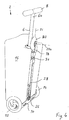
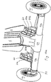
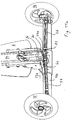
- eine vergrößerte abschnittsweise Ansicht auf die Unterseite des hinteren Endabschnittes des Trittbrettes des fahrbaren Gerätes von
Fig. 1 im Betriebszustand; - Fig. 7
- eine vergrößerte ausschnittsweise Ansicht auf die Unterseite des hinteren Endabschnittes des Trittbrettes des fahrbaren Gerätes von
Fig. 1 im Ruhezustand; - Fig. 8
- eine vergrößerte ausschnittsweise Ansicht des Verbindungsbereiches zwischen dem Trittbrett und einem Querbalken des fahrbaren Gerätes von
Fig. 1 im Ruhezustand; - Fig. 9
- eine perspektivische Darstellung eines fahrbaren Gerätes gemäß einem zweiten bevorzugten Ausführungsbeispiel bei abgenommenem Gepäckstück im Betriebszustand;
- Fig. 10
- eine perspektivische Darstellung des fahrbaren Gerätes von
Fig. 9 mit daran angebrachten Halteclips im Ruhezustand; - Fig. 10a
- eine vergrößerte ausschnittsweise Ansicht von
Fig. 10 mit abgenommenen Halteclips; - Fig. 11
- eine perspektivische Darstellung des fahrbaren Gerätes von
Fig. 9 mit in einer Lenkstellung eingeschlagenen Vorderrädern im Ruhezustand; - Fig. 11a
- eine vergrößerte ausschnittsweise Ansicht von
Fig. 11 ; - Fig. 12
- eine perspektivische Darstellung des fahrbaren Gerätes von
Fig. 9 mit in die Mittelstellung eingerasteter Lenkung im Ruhezustand; und - Fig. 12a
- eine vergrößerte ausschnittsweise Ansicht der Darstellung von
Fig. 12 . - In den
Figuren 1 bis 8 ist eine bevorzugte erste Ausführung eines fahrbaren Gerätes 2 gezeigt, das nach Art eines klappbaren Rollers mit einem Trittbrett 4 und einer Griffstütze 6 ausgebildet ist. In denFiguren 1 und2 ist das fahrbare Gerät 2 in einem aufgeklappten Betriebszustand gezeigt, in dem die Griffstütze 6 in einem Winkel von etwas weniger als 90° gegenüber dem horizontal ausgerichteten Trittbrett 4 angeordnet ist. Somit steht im dargestellten Ausführungsbeispiel die Griffstütze 6 im Betriebszustand nahezu aufrecht, wobei ihr distales Ende 6a, das einen Griff 8 trägt, gleichzeitig das obere Ende bildet. Das proximale gegenüberliegende Ende 6b der Griffstütze 6 ist auf einem Querbalken 10 montiert, der im dargestellten Ausführungsbeispiel, in Fahrtrichtung gemäß Pfeil A betrachtet, vor dem Trittbrett 4 und unterhalb der vom Trittbrett 4 gebildeten Ebene angeordnet ist. Wie beispielsweiseFig. 1 erkennen lässt, ist an dem einen Ende des Querbalkens 10 ein erstes Vorderrad 12 um eine Drehachse 12a und am gegenüberliegenden anderen Ende des Querbalkens 10 ein zweites Vorderrad 14 um eine Drehachse 14a drehbar gelagert. - Im dargestellten Ausführungsbeispiel ist ferner ein Gepäckstück 16 an der Griffstütze 6 und auf dem Querbalken 10 befestigt. Somit übernimmt im dargestellten Ausführungsbeispiel das fahrbare Gerät 2 die Funktion eines fahrbaren Gepäckstückes oder Rollkoffers. Wie insbesondere die
Figuren 1 und3 ferner erkennen lassen, weist im dargestellten Ausführungsbeispiel das Gepäckstück 16 einen länglichen, nach innen gewölbten Abschnitt 16a auf, durch den sich an der Außenseite des Gepäckstückes 16 entlang die Griffstütze 6 erstreckt. Wie insbesondereFig. 1 ferner erkennen lässt, ist die Länge des Querbalkens 10 auf die Breite des unteren Abschnittes des Gepäckstückes 16 entsprechend abgestimmt, so dass die Vorderräder 12, 14 außerhalb des Gepäckstückes 16 liegen. In diesem Zusammenhang sei jedoch darauf hingewiesen, dass die Verwendung und Montage eines Gepäckstückes nicht zwingend notwendig ist, sondern stattdessen auch andere Arten von Nutzlasten angeordnet werden können oder das dargestellte fahrbare Gerät 2 auch ohne jegliche Nutzlast verwendet werden kann. - Zum Lenken des fahrbaren Gerätes 2 kann ein entsprechender Lenkmechanismus vorgesehen sein, der in den
Figuren 1 bis 8 nicht dargestellt ist. Hierzu dient dann die Griffstütze 6 als Lenkstange, die durch entsprechendes Verschwenken des Griffes 8 um ihre Längsachse in Lenkrichtung verdrehbar ist. Ferner sind in diesem Fall die beiden Vorderräder 12, 14 um eine in den Figuren nicht dargestellte Schwenkachse verschwenkbar, die die Lenkachse bildet und gewöhnlich etwa in einem rechten Winkel oder in einem nahezu rechten Winkel gegenüber der jeweiligen Drehachse 12a bzw. 14a gerichtet ist und im Betriebszustand im Wesentlichen etwa aufrecht steht. Der nicht dargestellte Lenkmechanismus wandelt die Drehbewegung der Griffstütze 6 um deren Längsachse in eine simultane Lenkbewegung der beiden Vorderräder 12, 14 um die zuvor erwähnten Schwenkachsen um. In diesem Zusammenhang sei noch angemerkt, dass die beiden Vorderräder 12, 14 und somit deren Drehachsen 12a, 14a im Wesentlichen stets etwa parallel zueinander ausgerichtet sind und im Falle des Geradeauslaufs die beiden Drehachsen 12a, 14a im Wesentlichen miteinander fluchten. - Wie die Figuren ferner erkennen lassen, ist am hinteren bzw. distalen Ende 4a des Trittbrettes 4 eine Gabel 18 angeordnet, an der zwischen deren Schenkeln ein Hinterrad 20 um eine Drehachse 20a drehbar gelagert ist. Grundsätzlich ist es auch denkbar, mehr als ein Hinterrad vorzusehen, die beispielsweise hintereinander oder nebeneinander angeordnet sind. Somit bildet die Gabel 18 ein Lager für das Hinterrad 20 am Trittbrett 4. Zwar ist die Gabel 18 ortsfest am hinteren Ende 4a des Trittbrettes 4 angeordnet, jedoch an diesem um eine Schwenkachse 21 verschwenkbar gelagert, welche etwa in Längsrichtung des Trittbrettes 4 und etwa parallel zu einer vom Trittbrett 4 aufgespannten virtuellen Ebene und somit in dem in den
Figuren 1 und2 gezeigten Betriebszustand auch etwa in Fahrtrichtung gemäß Pfeil A verläuft. Somit erstreckt sich die Drehachse 20a des Hinterrades 20 etwa rechtwinklig zur Schwenkachse 21. Dies bedeutet, dass bei Verdrehen der Gabel 18 um die Schwenkachse 21 die Drehachse 20a des Hinterrades 20 und somit das Hinterrad 20 selbst eine Schwenkbewegung um die Schwenkachse 21 ausführt. Im Betriebszustand gemäß denFiguren 1 und2 , in dem sich das fahrbare Gerät 2 in seinem fahrbereiten Zustand befindet, nimmt die Gabel 18 eine solche Schwenkstellung ein, dass das Hinterrad 20 etwa aufrecht steht und somit dessen Drehachse 20a etwa horizontal verläuft. - Wie bereits zuvor erwähnt, ist das fahrbare Gerät 2 nach Art eines klappbaren Rollers ausgebildet, indem das Trittbrett 4 und die Griffstütze 6 in eine Platz sparende Ruhestellung für einen einfacheren Transport oder eine Platz sparende Aufbewahrung zusammengeklappt werden können. Hierzu ist am vorderen bzw. distalen Ende 4b des Trittbrettes 4 ein gabelförmiges Gelenkstück 22 befestigt, welches oberhalb des Querbalkens 10 am benachbarten bzw. proximalen Ende 6b der Griffstütze 6 um eine Schwenkachse 23 schwenkbar befestigt ist, die insbesondere in
Fig. 1 sowie inFig. 3 , die einen Zwischenzustand zwischen dem in denFiguren 1 und2 gezeigten Betriebszustand und einen zusammengeklappten Ruhezustand abbildet, schematisch gezeigt ist. Wie die schematische Darstellung der Schwenkachse 23 inFig. 3 ferner erkennen lässt, verläuft die Schwenkachse 23 etwa parallel zu den Drehachsen 12a, 14a der beiden Vorderräder 12, 14 (Fig. 1 ), wenn diese in Geradeausrichtung stehen, und auch etwa parallel zum Querbalken 10 sowie ferner parallel zu einer vom Trittbrett 4 aufgespannten virtuellen Ebene und ist außerdem im Betriebszustand gemäß denFiguren 1 und2 etwa horizontal ausgerichtet. Somit bilden das Gelenkstück 22 und das proximale Ende 6b der Griffstütze 6 gemeinsam ein Klappgelenk mit der erwähnten Schwenkachse 23. In diesem Zusammenhang sei noch angemerkt, dass eine in den Figuren nicht dargestellte Arretiereinrichtung vorgesehen ist, um in dem in denFiguren 1 und2 gezeigten Betriebszustand die Griffstütze 6 gegenüber dem Trittbrett 4 zu arretieren und dadurch ein versehentliches Zusammenklappen zu verhindern. - Um das fahrbare Gerät 2 vom Betriebszustand gemäß den
Figuren 1 und2 in einen Ruhezustand zu verbringen, wird das Trittbrett 4 nach Lösen einer eventuell vorhandenen Arretierungseinrichtung um die Schwenkachse 23 in Richtung des inFig. 3 gezeigten Pfeils B und somit in Richtung auf die Griffstütze 6 verschwenkt, bis das Trittbrett 4 und die Griffstütze 6 zusammengeklappt sind. In dieser Stellung befindet sich das fahrbare Gerät 2 in einem Ruhezustand, wie in denFiguren 4 und5 gezeigt ist. Während also im Betriebszustand gemäß denFiguren 1 und2 das hintere Ende 4a des Trittbrettes 4 einen maximalen Abstand von der Griffstütze 6 einnimmt, ist dieser Abstand im Ruhezustand gemäß denFiguren 4 und5 auf ein Minimum reduziert. Im dargestellten Ausführungsbeispiel liegen das Trittbrett 4 und die Griffstütze 6 im Ruhezustand gemäß denFiguren 4 und5 im Wesentlichen parallel nebeneinander. Der längliche, am Gepäckstück 16 nach innen gewölbte Abschnitt 16a besitzt eine solche Breite, dass er das hochgeklappte Trittbrett 4 im Ruhezustand im Wesentlichen vollständig aufnimmt, wieFig. 5 erkennen lässt. Eine solche Anordnung hat den Vorteil, dass im Ruhezustand das Trittbrett 4 am Gepäckstück 16 versenkt angeordnet ist und somit im Wesentlichen bündig mit der benachbarten Seitenfläche des Gepäckstückes 16 abschließt und nicht von dieser störend hervorsteht. Um bei Bedarf auch die Griffstütze 6 in eine platzsparende Stellung zu bringen, kann diese aus mindestens zwei zueinander teleskopierbar angeordneten Abschnitten bestehen, welche im Ruhezustand zur Verkürzung der Griffstütze 6 ineinander geschoben werden können, bis der Griff 8 auf der Oberseite des Gepäckstückes 16 aufliegt; in den Figuren ist die Teleskopierbarkeit der Griffstütze 6 allerdings nicht dargestellt. - Wie ein Vergleich des in
Figuren 4 und5 gezeigten Ruhezustandes mit dem in denFiguren 1 und2 gezeigten Betriebszustand in Verbindung mit dem inFig. 3 gezeigten Zwischenzustand erkennen lässt, wird beim Verschwenken des Trittbrettes 4 in Richtung des Pfeils B gemäßFig. 3 vom Betriebszustand gemäß denFiguren 1 und2 in den Ruhezustand gemäß denFiguren 4 und5 die Gabel 18 einer Schwenkbewegung um die Schwenkachse 21 in Richtung des Pfeils C gemäßFig. 3 unterworfen. Durch die Klapp- bzw. Schwenkbewegung in Richtung des Pfeils B gemäßFig. 3 wird dadurch das Hinterrad 20 von einer gegenüber dem Trittbrett 4 im Wesentlichen aufrechten Stellung im Betriebszustand durch eine Schwenkbewegung um etwa 90° in eine sog. Quer-Position im Ruhezustand verbracht, in der es nun etwa in einer vom Trittbrett 4 aufgespannten virtuellen Ebene liegt. Dadurch befindet sich das Hinterrad 20 im Ruhezustand in einer Platz sparenden Anordnung, da es zum Trittbrett 4 eine Art Verlängerung bildet und nicht mehr quer von diesem hervorsteht. Diese Platz sparende Positionierung des Hinterrades 20 in der Ruhestellung ist insbesondere inFig. 5 gut erkennbar. - Damit während der beschriebenen Schwenkbewegung in Richtung des Pfeils B gemäß
Fig. 3 automatisch die um die Schwenkachse 21 schwenkbar am hinteren Ende 4a des Trittbrettes 4 gelagerte Gabel 18 der zuvor beschriebenen Schwenkbewegung in Richtung des Pfeils B gemäßFig. 3 unterworfen wird, ist erfindungsgemäß eine besondere Mechanik vorgesehen, die die Schwenkbewegung in Richtung des Pfeils B in eine Schwenkbewegung des Hinterrades 20 in Richtung des Pfeils C umwandelt. Wie insbesondere dieFiguren 3 und4 erkennen lassen, ist an einem am Querträger 10 unterhalb des Trittbrettes 4 ausgebildeten zusätzlichen Gelenk 26 eine Zug-Schub-Stange 28 angelenkt, die an der Unterseite 4b des Trittbrettes 4 geführt und mit ihrem hinteren bzw. distalen Ende mit einem Getriebe 30 gekoppelt ist. Das Getriebe 30 ist im dargestellten Ausführungsbeispiel an der Unterseite 4b des hinteren Endes 4a des Trittbrettes 4 angeordnet, wie dieFiguren 6 und7 erkennen lassen. Dieses Getriebe 20 wandelt eine längsaxiale Bewegung der Zug-Schub-Stange 28 in eine Drehbewegung der Gabel 18 um die Schwenkachse 21 um. - Wie die
Figuren 6 und7 erkennen lassen, weist das Getriebe 30 zwei voneinander axial beabstandete Lager 32 und eine Drehhülse 34 auf, die zwischen den Lagern 32 liegt und an diesen um die Schwenkachse 21 drehbar, jedoch in axialer Richtung ortsfest gelagert ist. Im Mantel der drehbar gelagerten Drehhülse 34 sind zwei gegenüberliegende und gegenüber der Schwenkachse 21 winklig bzw. geneigt verlaufende schlitzförmige Nuten 36 ausgebildet, durch die sich ein Querstift 38 erstreckt. Der Querstift 38 ist rechtwinklig zur Schwenkachse 21 angeordnet und mit seinen Enden nicht nur durch die beiden erwähnten schlitzförmigen Nuten 36 im Mantel der Drehhülse 34, sondern auch durch benachbarte Längsschlitze 40 gesteckt, die etwa in Längsrichtung des Trittbrettes 4 und parallel zur Zug-Schub-Stange 28 verlaufen und in von der unteren Seite 4b des Trittbrettes 4 vorspringenden Abschnitten 4c ausgebildet sind. Diese beiden vorspringenden Abschnitte 4c haben eine sich in Längsrichtung des Trittbrettes 4 erstreckende längliche Form und sind voneinander beabstandet, um zwischen sich eine Kammer zur Aufnahme der Lager 32 und der Drehhülse 34 zu bilden. Das hintere bzw. distale Ende der Zug-Schub-Stange 28 ist lose durch das näher liegende Lager 32 in die Drehhülse 34 geführt und dort mit dem Querstift 38 starr gekoppelt. - Eine Bewegung der Zug-Schub-Stange 28 in Richtung deren Längsachse hat somit eine Bewegung des Querstiftes 38 in Richtung quer zu dessen Längsachse zur Folge, wodurch sich der Querstift 38 entlang der Längsschlitze 40 bewegt, in denen der Querstift 38 somit geführt wird. Gleichzeitig findet auch eine Zwangsführung des Querstiftes 38 entlang der Nuten 36 in der Drehhülse 34 statt. Da die Drehhülse 34 drehbar, jedoch in axialer Richtung ortsfest gelagert ist und die schlitzförmigen Nuten 36 winklig angeordnet sind, bewirkt die Zwangsführung des Querstiftes 38 entlang der Nuten 36 eine Rotationsbewegung der Drehhülse 34. Somit wird eine längsaxiale Bewegung der Zug-Schub-Stange 28 in eine rotatorische Bewegung der Drehhülse 34 um die Schwenkachse 21 umgewandelt. Da die Gabel 18 mit der Drehhülse 34 drehfest verbunden ist, führt die Drehbewegung der Drehhülse 34 zu einer entsprechenden Drehbewegung der Gabel 18 und somit des Hinterrades 20 um die Schwenkachse 21 in Richtung des Pfeils C. Während in
Fig. 6 das Hinterrad 20 im Betriebszustand und somit in seiner Fahrstellung gezeigt ist, befindet sich das Hinterrad 20 gemäß der Darstellung vonFig. 7 in seiner zuvor erwähnten Quer-Position im Ruhezustand des fahrbaren Gerätes 2. - In
Fig. 8 ist die Anlenkung der Zug-Schub-Stange mit ihrem proximalen Ende 28b am Querbalken 10 dargestellt. Hierzu ist ein Gelenkstift 42 vorgesehen, über den das proximale Ende 28b der Zug-Schub-Stange 28 am Querbalken 10 um eine Gelenkachse 42a schwenkbar gelagert ist. Somit wird das Gelenk 26 für die Anlenkung der Zug-Schub-Stange 28 am Querbalken 10 im wesentlichen durch das proximale Ende 28b der Zug-Schub-Stange 28 und den Gelenkstift 42 gebildet. Da die Schwenkachse 23, um die das Trittbrett 4 gegenüber der Griffstütze 6 geklappt bzw. verschwenkt wird, in einem Abstand von der Gelenkachse 42a verläuft, wieFig. 8 erkennen lässt, führt eine Schwenkbewegung des Trittbrettes 4 gegenüber der Griffstütze 6 zu einer axialen Längsbewegung der Zug-Schub-Stange 28 gegenüber dem Trittbrett 4, woraus dann die zuvor beschriebene Drehbewegung der Drehhülse 34 des Getriebes 30 resultiert. - Ergänzend sei noch angemerkt, dass aufgrund der zuvor beschriebenen Anordnung nicht nur eine Klapp- bzw. Schwenkbewegung des Trittbrettes 4 in Richtung des Pfeils B (
Fig. 3 ) und somit in Richtung auf die Griffstütze 6 zu einer Schwenkbewegung des Hinterrades 20 von seiner aufrechten Stellung in seine Quer-Position führt, sondern dass jene Bewegungsabläufe auch in umgekehrter Richtung möglich sind, also bei Bewegung des Trittbrettes 4 von dem Ruhezustand in den Betriebszustand und somit beim Aufklappen von Trittbrett 4 und Griffstütze 6 das Hinterrad 20 von seiner Quer-Position gemäßFig. 7 wieder in seine aufrechte Stellung gemäß denFiguren 1 ,2 und6 gedreht wird. - In den
Figuren 9 bis 12a ist ein fahrbares Gerät 2a gemäß einer bevorzugten zweiten Ausführung gezeigt. Sofern diese zweite Ausführung Komponenten aufweist, die den entsprechenden Komponenten der ersten Ausführung gemäß denFiguren 1 bis 8 gleichen oder zumindest mit diesen hinsichtlich ihrer Funktion vergleichbar sind, werden für die zweite Ausführung die gleichen Bezugszeichen wie für die erste Ausführung verwendet, wobei hinsichtlich dieser übereinstimmenden Komponenten zur Vermeidung von Wiederholungen auf die entsprechenden Teile der Beschreibung der ersten Ausführung verwiesen wird. - Ein erkennbarer Unterschied der zweiten Ausführung gegenüber der ersten Ausführung besteht darin, dass der das proximale Ende 6b der Griffstütze 6 tragende und die beiden Vorderräder 12, 14 drehbar lagernde Querbalken 10a einen runden Querschnitt besitzt und somit als Rundrohr ausgebildet ist.
- Ferner lässt
Fig. 9 ein Lagerteil 44 erkennen, an dem der Querbalken 10a befestigt ist, mit ihrem proximalen Ende 6b die Griffstütze 6 angeordnet, welche vom Lagerteil 44 emporragt, und das Gelenkstück 22 schwenkbar befestigt ist, welches am vorderen bzw. distalen Ende 4b des Trittbrettes 4 ist. - Zwar ist das fahrbare Gerät 2a gemäß der zweiten Ausführung in den
Figuren 9 bis 12a ohne ein Gepäckstück dargestellt, jedoch wie die erste Ausführung zur Aufnahme eines Gepäckstückes oder einer sonstigen Nutzlast vorgesehen, so dass auch das fahrbare Gerät 2a gemäß der zweiten Ausführung die Funktion eines fahrbaren Gepäckstückes oder Rollkoffers übernimmt. - Zur Befestigung eines Gepäckstückes auf dem rohrförmigen Querbalken 10a werden für die zweite Ausführung Halteclips 60 verwendet, wie in den
Figuren 10 und10a gezeigt ist. Im dargestellten Ausführungsbeispiel weisen die Halteclips 60 einen plattenförmigen Grundkörper 60a auf, der mit seiner dem Betrachter vonFig. 10a zugewandten Seite an einem nicht dargestellten Gepäckstück und insbesondere an dessen Unterseite befestigt ist. WieFig. 10a ferner erkennen lässt, sind an der gegenüberliegenden Seite der plattenförmigen Grundkörper 60a bügel- bzw. hakenförmige Arretierabschnitte 60b ausgebildet, die im montierten Zustand den Querbalken 10a umgreifen, wodurch die Halteclips 60 gemäß der Abbildung vonFig. 10 am Querbalken 10a lösbar arretiert sind. Die Halteclips 60 bestehen bevorzugt aus Kunststoff und sind die bügel- bzw. hakenförmig gebogenen Eingriffsabschnitte 60b für die lösbare Arretierung am plattenförmigen Grundkörper 60a elastisch angeordnet. - Im Gegensatz zur ersten Ausführung gemäß den
Figuren 1 bis 8 ist in denFiguren 9 bis 12a , das fahrbare Gerät 2a gemäß zweitem Ausführungsbeispiel, sofern erkennbar, mit einem Lenkmechanismus 50 dargestellt. Hierzu sind die beiden Vorderräder 12, 14 jeweils um eine Schwenkachse verschwenkbar, die die Lenkachse bildet und gewöhnlich etwa in einem rechten Winkel oder in einem nahezu rechten Winkel gegenüber der Drehachse der Vorderräder 12, 14 (vgl. hierzu die Drehachsen 12a, 14a inFig. 1 ) gerichtet ist und im Betriebszustand im Wesentlichen etwa aufrecht steht, wie inFig. 9 die dem Vorderrad 14 zugeordnete Schwenkachse 14b erkennen lässt. An den beiden äußeren Enden des Querbalkens 10a ist somit jeweils ein Achslager 52 um die erwähnte Schwenkachse schwenkbar gelagert, und an den Achslagern 52 sind die Vorderräder 12, 14 drehbar gelagert. Wie bei der ersten Ausführung dient auch hier die Griffstütze 6 als Lenkstange, die durch entsprechendes Verschwenken des Griffes 8 um ihre Mittel- bzw. Längsachse 6c in Lenkrichtung verdrehbar ist. Hierzu ist die Griffstütze 6 mit ihrem proximalen Ende 6b im Lagerteil 44 entsprechend drehbar gelagert und mit einem Drehhebel 54 versehen, der im dargestellten Ausführungsbeispiel an der Unterseite des Lagerteils 44 angeordnet ist. WieFig. 9 ferner erkennen lässt, sind am freien Ende 54a des Drehhebels 54 Lenkstangen 56 angelenkt, die mit ihrem gegenüberliegenden Ende an den schwenkbaren Achslagern 52 der Vorderräder 12, 14 angelenkt sind. Somit bewirkt eine Drehung der Griffstütze 6 eine Bewegung der Lenkstangen 56 etwa in Richtung ihrer Längserstreckung, wodurch das Achslager 52 des einen Vorderrades 12 bzw. 14 auf Druck und das Achslager 52 des anderen Vorderrades 14 bzw. 12 auf Zug beansprucht wird. Dies hat zur Folge, dass die Achslager 52 beider Vorderräder gleichzeitig in dieselbe Richtung verschwenkt werden. Auf diese Weise wandelt der Lenkmechanismus 50 eine Drehbewegung der Griffstütze 6 um deren Längsachse 6c in eine simultane Lenkbewegung der beiden Vorderräder 12, 14 um. - Wie insbesondere
Fig. 11a erkennen lässt, ist am Gelenk 26, das am gabelförmigen Gelenkstück 22 um eine etwa parallel zum Querbalken 10a verlaufende Drehachse 26a drehbar gelagert ist und an dem die Zug-Schub-Stange 28 angelenkt ist, ein radialer Zapfen 70 und passend für diesen radialen Zapfen 70 im freien Ende 54a des Drehhebels 54 eine entsprechende Aussparung 72 ausgebildet. Dabei sind die Anordnung und Ausrichtung des Drehhebels 54 und der Aussparung 72 in dessen freiem Ende 54a sowie des Zapfens 70 am Gelenk 26 so getroffen, dass im Ruhezustand die Aussparung 72 im freien Ende 54a des Drehhebels 54 den am Gelenk 26 ausgebildeten radialen Stift 70 aufnimmt und somit der Stift 70 in die Aussparung 72 einrastet, wenn die Griffstütze 6 in eine solche Lenkstellung gedreht wird, in der sich die Vorderräder 12, 14 in ihrer Geradeausstellung befinden, wie in denFiguren 12 und12a gezeigt ist. - Demnach bilden der radiale Stift 70 am Gelenk 26 und die Aussparung 72 im freien Ende 54a des Drehhebels 54 gemeinsam eine Arretiereinrichtung zur Arretierung des Lenkmechanismus 50 und somit der Vorderräder 12, 14 in die neutrale Mittelstellung für Geradeauslauf. Dabei wird die Arretierung nur dann wirksam, wenn sich das fahrbare Gerät 2a in seinem Ruhezustand gemäß den
Figuren 10 bis 12a befindet, in der das Trittbrett 4 in Richtung auf die Griffstütze 6 geklappt ist. Denn die Überführung vom Betriebszustand in den Ruhezustand durch Verschwenken des Trittbrettes 4 in Richtung auf die Griffstütze 6 hat zur Folge, dass auch das Gelenk 26 einer entsprechenden Drehbewegung unterworfen wird. Erst aufgrund dieser Drehbewegung gelangt der Stift 70 in den Bereich des Drehhebels 54 und somit in 'Flucht' mit dessen freiem Ende 54a und der darin ausgebildeten Aussparung 72, um dann in diese einzurasten, wie ein Vergleich derFiguren 11 und11a mit denFiguren 12 und12a erkennen lässt. Wird dagegen das fahrbare Gerät 2a in seinen Betriebszustand gemäßFig. 9 überführt, so wird das Gelenk 26 einer Schwenkbewegung unterworfen, die den Stift 70 aus dem Bereich des Drehhebels 54 herausführt, wodurch ein Einrasten des Stiftes 70 in die Aussparung 72 nicht stattfinden kann. Letzteres muss ohnehin im Betriebszustand vermieden werden, da ansonsten die Lenkung unbeabsichtigt stillgelegt würde. Dies macht jedoch im normalen Betrieb keinen Sinn und ist deshalb unerwünscht. Demgegenüber ist im Ruhezustand des Trittbrettes 4 eine Arretierung der Lenkung von Vorteil, um eine Vergrößerung der effektiven Breite durch Einschlagen der Vorderräder insbesondere in eine der beiden Endstellungen zu verhindern, was ansonsten einen erhöhten Platzbedarf im Ruhezustand zur Folge hätte. Ein weiterer Vorteil der Arretierungsmöglichkeit für die Lenkung besteht darin, dass im Ruhezustand das fahrbare Gerät 2a mit daran befestigtem Gepäckstück nach Art eines Trolleys verwendet und somit vom Benutzer hinter sich hergezogen werden kann. - Abschließend sei noch darauf hingewiesen, dass unter "Ruhezustand" grundsätzlich nicht ein unbenutzter Zustand für das fahrbare Gerät zu verstehen ist, sondern sich die Angabe "Ruhezustand" auf eine Situation bezieht, in der das Trittbrett 4 in eine Ruhestellung an die Griffstütze 6 geklappt ist und sich dadurch tatsächlich im unbenutzten Zustand befindet. Somit lässt sich im Ruhezustand das fahrbare Gerät zwar nicht als Roller benutzen; demgegenüber ist es aber ohne Weiteres möglich, das fahrbare Gerät im Ruhezustand beispielsweise als Trolley zu benutzen.
Claims (14)
- Fahrbares Gerät, mit
einem flächigen Element (4),
mindestens einem um eine erste Drehachse (12a) rotierend gelagerten ersten Rad (12),
einer Griffstütze (6), die ein vom flächigen Element (4) distales Ende (6a), das einen Griff (8) trägt, und ein zum flächigen Element (4) proximales Ende (6b) aufweist,
einem benachbart zum ersten Rad (12) befindlichen Klappgelenk, das das proximale Ende (6b) der Griffstütze (6) mit dem flächigen Element (4) derart um eine erste Schwenkachse (23) schwenkbar verbindet, dass in einem Betriebszustand die Griffstütze (6) gegenüber dem flächigen Element (4) in einem, vorzugsweise etwa rechten oder nahezu rechten, Winkel ausgerichtet ist und somit das distale Ende (6a) der Griffstütze (6) einen maximalen Abstand zum flächigen Element (4) aufweist und in einem Ruhezustand das distale Ende (6a) der Griffstütze (6) einen minimalen Abstand vom flächigen Element (4) aufweist,
mindestens einem um eine zweite Drehachse (20a) rotierend gelagerten zweiten Rad (20), das an einem von der Anordnung aus erstem Rad und Klappgelenk beabstandeten entfernten Ende des flächigen Elementes (4) angeordnet ist,
wobei das erste Rad (12) zusätzlich um eine winklig, vorzugsweise etwa rechtwinklig, zur ersten Drehachse (12a) verlaufende dritte Schwenkachse derart schwenkbar gelagert ist, dass eine Schwenkbewegung um diese dritte Schwenkachse eine Änderung der Fahrtrichtung bewirkt, die Griffstütze (6) eine Lenkstange ist und eine Lenkmechanik (50) vorgesehen ist, die bestimmte Bewegungen der Griffstütze (6) in Schwenkbewegungen des ersten Rades (12) um die dritte Schwenkachse umwandelt, in axialem Abstand vom ersten Rad (12) ein drittes Rad (14) vorgesehen ist, das in der gleichen Weise wie das erste Rad (12) gelagert ist, wobei der axiale Abstand mindestens geringfügig größer als die Breite des zwischen den ersten und dritten Rädern (12, 14) befindlichen Abschnittes des an der Griffstütze (6) zu befestigenden Gepäckstückes (16) ist, das dritte Rad (14) zusätzlich um eine winklig, vorzugsweise etwa rechtwinklig, zur ersten Drehachse (14a) verlaufende vierte Schwenkachse (14b) derart schwenkbar gelagert ist, dass eine Schwenkbewegung um diese vierte Schwenkachse (14b) eine Änderung der Fahrtrichtung bewirkt, und die Lenkmechanik (50) vorgesehen ist, bestimmte Bewegungen der Griffstütze (6) ebenfalls in Schwenkbewegungen des dritten Rades (14) um die vierte Schwenkachse umzuwandeln,
und mit Arretierungsmitteln (54, 54a, 70, 72) zur Arretierung der Lenkmechanik (50), welche so ausgebildet sind, dass sie nur im Ruhezustand die Lenkmechanik (50) in einer neutralen Stellung, vorzugsweise etwa für den Geradeauslauf, arretieren,
dadurch gekennzeichnet, dass die Arretierungsmittel einen Drehhebel (54), der am proximalen Ende (6b) der Griffstütze (6) gegenüber dieser drehfest angeordnet ist und in dessen freiem Ende (54a) eine Aussparung (72) ausgebildet ist, und einen Stift (70) aufweisen, der radial an einem Gelenk (26) angeordnet ist, das um eine etwa parallel zur ersten Schwenkachse (23) verlaufende fünfte Schwenkachse (26a) schwenkbar und gegenüber dem flächigen Element (4) drehfest angeordnet ist, wobei die Anordnung und Ausrichtung des Drehhebels (54) und der Aussparung (72) in dessen freiem Ende (54a) sowie des radialen Stiftes (70) am Gelenk (26) derart getroffen ist, dass im Ruhezustand der Stift (70) von der Aussparung (72) aufgenommen wird, wenn die Griffstütze (6) in eine solche Längsstellung gedreht wird, in der sich das erste Rad (12) und das dritte Rad (14) in ihrer Geradeausstellung befinden. - Gerät nach Anspruch 1,
dadurch gekennzeichnet, dass das zweite Rad (20) zusätzlich um eine etwa in Fahrtrichtung (A) verlaufende zweite Schwenkachse (21) schwenkbar am flächigen Element (4) angeordnet und mit der Griffstütze (6) über einen Mechanismus (28, 30) gekoppelt ist, der eine Schwenkbewegung der Griffstütze (6) gegenüber dem flächigen Element (4) um die erste Schwenkachse (23) in eine Schwenkbewegung des zweiten Rades (20) um die zweite Schwenkachse (21) derart umwandelt, dass die zweite Drehachse (20a) des zweiten Rades (20) in dem Ruhezustand einen größeren Winkel gegenüber dem flächigen Element (4) als in dem Betriebszustand aufweist. - Gerät nach Anspruch 2, dadurch gekennzeichnet, dass die zweite Drehachse (20a) des zweiten Rades (20) gegenüber dem flächigen Element (4) in dem Ruhezustand in einem Winkel von etwa 90° und in dem Betriebszustand in einem Winkel von etwa 0° ausgerichtet ist.
- Gerät nach Anspruch 2 oder 3, dadurch gekennzeichnet, dass der Mechanismus eine Zug-Schub-Stange (28) aufweist, die über ein vom Klappgelenk beabstandetes Gelenk (26) an der Griffstütze (6) angelenkt, entlang des flächigen Elementes (4) geführt und mit einem am flächigen Element (4) angeordneten Getriebe (30) gekoppelt ist, welches eine Längsbewegung der Zug-Schub-Stange (28) in die Schwenkbewegung des zweiten Rades (20) um die zweite Schwenkachse (21) umwandelt.
- Gerät nach Anspruch 4, dadurch gekennzeichnet, dass das Gelenk (26) an einer Stelle der Griffstütze (6), welche sich im Betriebszustand an oder unterhalb der Unterseite (4b) des flächigen Elementes (4) befindet, und die Zug-Schub-Stange (28) an der Unterseite des flächigen Elementes (4b) angeordnet ist.
- Gerät nach Anspruch 4 oder 5, dadurch gekennzeichnet, dass das Getriebe (30) einen um die zweite Schwenkachse (21) drehbar, jedoch in axialer Richtung im Wesentlichen ortsfest gelagerten, vorzugsweise hülsenförmigen, Rotationskörper (34) aufweist, an dessen Mantel mindestens eine winklig zur zweiten Schwenkachse (21) verlaufende Nut (36) ausgebildet ist, in die ein an der Zug-Schub-Stange (28) angeordnetes, stiftförmiges Nockenelement (38) ragt.
- Gerät nach mindestens einem der Ansprüche 2 bis 6, dadurch gekennzeichnet, dass das zweite Rad (20) um die zweite Drehachse (20a) drehbar an einer Gabel (18) gelagert ist, welche um die zweite Schwenkachse (21) schwenkbar am flächigen Element (4) angeordnet ist.
- Gerät nach den Ansprüchen 6 und 7, dadurch gekennzeichnet, dass die Gabel (18) und der Rotationskörper (34) axial zueinander ausgerichtet und drehfest miteinander verbunden sind.
- Gerät nach mindestens einem der vorangegangenen Ansprüche, dadurch gekennzeichnet, dass die Griffstütze mindestens zwei zueinander teleskopierbar angeordnete Elemente aufweist.
- Gerät nach mindestens einem der vorangegangenen Ansprüche, dadurch gekennzeichnet, dass die Griffstütze (6) Mittel zur, vorzugsweise mittigen und/oder symmetrischen, Befestigung eines Gepäckstückes (16) an der Griffstütze (6) aufweist.
- Gerät nach mindestens einem der vorangegangenen Ansprüche, gekennzeichnet durch Arretiermittel (60) zur lösbaren Arretierung eines Gepäckstückes an einem Abschnitt des fahrbaren Gerätes (2a), insbesondere einem Querbalken (10a).
- Gerät nach Anspruch 11, dadurch gekennzeichnet, dass die Arretiermittel Halteclips (60) aufweisen.
- Gerät nach mindestens einem der vorangegangenen Ansprüche, dadurch gekennzeichnet, dass im Ruhezustand die Griffstütze (6) und das flächige Element (4) im Wesentlichen parallel zueinander liegen.
- Gerät nach mindestens einem der vorangegangenen Ansprüche, dadurch gekennzeichnet, dass im Ruhezustand die Griffstütze (6) und das flächige Element (4) im Wesentlichen aneinander liegen.
Applications Claiming Priority (3)
| Application Number | Priority Date | Filing Date | Title |
|---|---|---|---|
| DE202010003434U DE202010003434U1 (de) | 2010-03-10 | 2010-03-10 | Fahrbares Gerät |
| PCT/EP2011/053620 WO2011110631A1 (de) | 2010-03-10 | 2011-03-10 | Fahrbares gerät |
| EP20110708799 EP2544781B1 (de) | 2010-03-10 | 2011-03-10 | Fahrbares gerät |
Related Parent Applications (1)
| Application Number | Title | Priority Date | Filing Date |
|---|---|---|---|
| EP20110708799 Division EP2544781B1 (de) | 2010-03-10 | 2011-03-10 | Fahrbares gerät |
Publications (2)
| Publication Number | Publication Date |
|---|---|
| EP2954938A1 EP2954938A1 (de) | 2015-12-16 |
| EP2954938B1 true EP2954938B1 (de) | 2020-06-17 |
Family
ID=43827849
Family Applications (2)
| Application Number | Title | Priority Date | Filing Date |
|---|---|---|---|
| EP20110708799 Active EP2544781B1 (de) | 2010-03-10 | 2011-03-10 | Fahrbares gerät |
| EP15167209.4A Active EP2954938B1 (de) | 2010-03-10 | 2011-03-10 | Klappbarer tretroller mit gepäckträger |
Family Applications Before (1)
| Application Number | Title | Priority Date | Filing Date |
|---|---|---|---|
| EP20110708799 Active EP2544781B1 (de) | 2010-03-10 | 2011-03-10 | Fahrbares gerät |
Country Status (7)
| Country | Link |
|---|---|
| US (1) | US8695999B2 (de) |
| EP (2) | EP2544781B1 (de) |
| JP (3) | JP5978532B2 (de) |
| CN (2) | CN105460137B (de) |
| DE (1) | DE202010003434U1 (de) |
| ES (2) | ES2819176T3 (de) |
| WO (1) | WO2011110631A1 (de) |
Families Citing this family (28)
| Publication number | Priority date | Publication date | Assignee | Title |
|---|---|---|---|---|
| US20130033012A1 (en) * | 2011-08-05 | 2013-02-07 | Hamid Arjomand | Convertible cargo container |
| FR2962403B1 (fr) * | 2010-07-07 | 2015-03-27 | Raoul Parienti | Tricycle ultraleger motorise electriquement |
| CN102351022A (zh) * | 2011-08-25 | 2012-02-15 | 上海江南工程塑胶有限公司 | 一种多功能折叠式运动滑板车 |
| CN104349973A (zh) * | 2012-02-13 | 2015-02-11 | A·扎伊德 | 城市车辆 |
| CN103029730B (zh) * | 2012-10-22 | 2015-06-03 | 李从道 | 手推车折叠机构 |
| GB2535802B (en) * | 2015-02-27 | 2020-12-30 | Hy Pro International Ltd | An item of luggage |
| CN104816743B (zh) * | 2015-05-25 | 2017-02-01 | 李宗进 | 多功能拉车 |
| JP6573491B2 (ja) * | 2015-06-18 | 2019-09-11 | 丈示 嶋 | 支圧金物に対する支柱の連結構造、柵体の設置構造及び流木導流システム |
| CN104943719A (zh) * | 2015-07-08 | 2015-09-30 | 平凉市老兵科技研发有限公司 | 一种便捷式多用车 |
| US10850760B2 (en) * | 2016-08-03 | 2020-12-01 | Richard Neal Shapiro | Foldable wheeled carrier including wheel folding actuation handle |
| USD832930S1 (en) * | 2016-10-13 | 2018-11-06 | Shenzhen Immotor Technology Co., Ltd. | Scooter |
| CN106741025A (zh) * | 2017-02-16 | 2017-05-31 | 深圳市福田区天健小学 | 轮滑购物车 |
| CN108146561A (zh) * | 2017-12-07 | 2018-06-12 | 郭正同 | 多功能脚踏摇摆车 |
| US10542806B2 (en) | 2018-04-25 | 2020-01-28 | Becklin Holdings, Inc. | Pull handle for a rolling case |
| USD864572S1 (en) | 2018-04-25 | 2019-10-29 | Becklin Holdings, Inc. | Pull handle for a rolling case |
| CN108657354B (zh) * | 2018-06-01 | 2020-02-07 | 柒小佰(深圳)科技有限公司 | 一种两轮和三轮可转换的折叠式儿童行李车 |
| CN108652887A (zh) * | 2018-06-07 | 2018-10-16 | 温州市人民医院 | 一种急救护理车 |
| CN110949588A (zh) * | 2018-09-27 | 2020-04-03 | 袁薇 | 拉杆式折叠电动车 |
| CN111252179B (zh) * | 2018-11-15 | 2021-09-17 | 本田技研工业(中国)投资有限公司 | 滑板车 |
| CN109850045B (zh) * | 2019-01-23 | 2024-03-29 | 永康市锐鹰工贸有限公司 | 一种折叠滑板车 |
| CN113493189B (zh) * | 2020-04-05 | 2023-07-07 | 左点实业(湖北)有限公司 | 一种制氧机拉杆 |
| JP7033751B2 (ja) * | 2020-05-29 | 2022-03-11 | 日本発條株式会社 | キックスケーター |
| US11932302B1 (en) | 2020-09-25 | 2024-03-19 | Honda Motor Co., Ltd. | Convertible compact electric transport device |
| CN112896257A (zh) * | 2021-01-13 | 2021-06-04 | 吴成迎 | 一种货物多层搬运装置 |
| CN113973570A (zh) * | 2021-10-21 | 2022-01-28 | 王有琴 | 一种农业除草装置 |
| DE102021127693A1 (de) | 2021-10-25 | 2023-04-27 | Fürst, Teresa und Stein, Max GbR (vertretungsberechtigter Gesellschafter: Teresa Fürst, 85540 Haar) | Gepäckhalterung für ein fahrzeug und fahrzeug |
| USD1041889S1 (en) * | 2024-01-16 | 2024-09-17 | Yiwu Qiaomai Daily Necessities Co., Ltd | Suitcase |
| USD1036588S1 (en) * | 2024-04-09 | 2024-07-23 | Chongjian Yang | Scooter |
Family Cites Families (36)
| Publication number | Priority date | Publication date | Assignee | Title |
|---|---|---|---|---|
| US5984326A (en) * | 1996-06-19 | 1999-11-16 | 500 Group, Inc. | Roller mechanism for container or cart |
| JP2922471B2 (ja) * | 1996-11-27 | 1999-07-26 | 郁▲じん▼實業股▲ぶん▼有限公司 | 自転車の荷物入れ |
| DE19849361B4 (de) * | 1998-10-27 | 2006-06-08 | Alexander Riest | Tretroller |
| WO2001072164A1 (de) * | 2000-03-28 | 2001-10-04 | Roeder Klaus | Gepäckstück mit rollen |
| DE10026184C2 (de) * | 2000-05-26 | 2002-06-13 | Rainer Mittl | Multifunktioneller Tretroller |
| US6460866B1 (en) * | 2000-10-20 | 2002-10-08 | Diece-Lisa Industries, Inc. | Combination wheeled vehicle and article carrier |
| DE10058466A1 (de) * | 2000-11-24 | 2002-06-06 | Moamar Nardone | Austausch-Vorderradanordnung für ein Rollerboard |
| FR2819478A1 (fr) * | 2001-01-16 | 2002-07-19 | Mickael Selam | Vehicule pliable et transformable, notamment en poussette et luge |
| TW480949U (en) * | 2001-05-03 | 2002-03-21 | Yi-Chiuan Shiu | Portable bag/case with sliding functions |
| US6688614B2 (en) * | 2001-08-31 | 2004-02-10 | Yi-Chuan Hsu | Portable bag/box having a sliding function |
| US6425589B1 (en) * | 2001-10-15 | 2002-07-30 | Kuo-Chen Wu | Golf bag functioning as a golf cart and a foot stand |
| JP2003146282A (ja) * | 2001-11-13 | 2003-05-21 | Seizo Miyoshi | 携帯自転車 |
| DE10204478A1 (de) * | 2002-02-05 | 2003-08-21 | Peter Hirschmann | Multifunktionales mobiles Gerät |
| US20040056442A1 (en) * | 2002-09-23 | 2004-03-25 | Joseph Ostrowski | Baggage scooter |
| WO2004028890A1 (ja) * | 2002-09-25 | 2004-04-08 | Kouji Kobayashi | 折り畳み自転車 |
| FR2849751B1 (fr) * | 2003-01-10 | 2005-04-08 | Phileas | Ensemble combine sac-patinette |
| US7246805B2 (en) * | 2003-12-19 | 2007-07-24 | Neal Phillip H | Apparatus and method for convertible cargo carrier |
| TWM257672U (en) * | 2004-06-29 | 2005-03-01 | Syndica Technologies Internat | Bicycle storage compartment and similar article |
| US7431311B2 (en) * | 2005-01-27 | 2008-10-07 | Michael Hughesdon Turner | Combination scooter/backpack |
| JP4043480B2 (ja) * | 2005-03-29 | 2008-02-06 | 倫代 小川 | 携帯・折り畳み式カート |
| CN2780602Y (zh) * | 2005-04-29 | 2006-05-17 | 黄德荣 | 手提万向滑板车 |
| DE102006042119B4 (de) * | 2005-09-13 | 2016-07-28 | GreenPack GmbH | Lastenroller |
| US7438302B2 (en) * | 2006-03-06 | 2008-10-21 | Steven L. Nichols | Scooter and event forum seat |
| CN2933106Y (zh) * | 2006-06-06 | 2007-08-15 | 吴兴红 | 滑板行李箱 |
| ES2311355B1 (es) * | 2006-06-09 | 2009-10-26 | Jose Gregorio Garcia Domingo | Mochila convertible. |
| DE102006049770A1 (de) * | 2006-10-21 | 2008-05-08 | Unterberg-Klitsch, Bärbel | Multifunktionaler zusammen klappbarer Transportwagen für Last- und Personentransport |
| ITMI20062409A1 (it) * | 2006-12-15 | 2008-06-16 | Von Bismarck Gregor Graf | Valigia provvista di ruote sterzanti estensibili |
| US7837206B1 (en) * | 2007-04-09 | 2010-11-23 | Freddy Theo Lee | Wheeled carrier scooter |
| DE202008001751U1 (de) * | 2008-02-07 | 2008-05-08 | Expresso Deutschland Gmbh | Rollkarre mit abklappbarem Trittbrett |
| GB0809278D0 (en) * | 2008-05-22 | 2008-06-25 | Re Creation Group Plc | Scooter and method of use thereof |
| CN100567074C (zh) * | 2008-06-11 | 2009-12-09 | 潘居然 | 一种多功能折叠行李车 |
| JP2010029549A (ja) * | 2008-07-30 | 2010-02-12 | Genesis:Kk | バッグ |
| US20100213680A1 (en) * | 2009-02-20 | 2010-08-26 | Andrew Massara | Convertible Scooterbag |
| US8282113B2 (en) * | 2009-06-01 | 2012-10-09 | Veal James W | Rideable luggage |
| US8201837B2 (en) * | 2009-10-21 | 2012-06-19 | Animations An Accessory Innovations Company | Skateboard backpack system |
| CN202193155U (zh) * | 2011-08-30 | 2012-04-18 | 张国庆 | 折叠式滑板车箱包 |
-
2010
- 2010-03-10 DE DE202010003434U patent/DE202010003434U1/de not_active Expired - Lifetime
-
2011
- 2011-03-10 EP EP20110708799 patent/EP2544781B1/de active Active
- 2011-03-10 JP JP2012556520A patent/JP5978532B2/ja active Active
- 2011-03-10 EP EP15167209.4A patent/EP2954938B1/de active Active
- 2011-03-10 CN CN201510390652.5A patent/CN105460137B/zh active Active
- 2011-03-10 CN CN201180022191.6A patent/CN102869414B/zh active Active
- 2011-03-10 ES ES15167209T patent/ES2819176T3/es active Active
- 2011-03-10 ES ES11708799.9T patent/ES2545114T3/es active Active
- 2011-03-10 WO PCT/EP2011/053620 patent/WO2011110631A1/de not_active Ceased
- 2011-03-10 US US13/583,653 patent/US8695999B2/en active Active
-
2016
- 2016-07-07 JP JP2016135191A patent/JP6298852B2/ja active Active
-
2017
- 2017-12-06 JP JP2017234530A patent/JP6444479B2/ja not_active Expired - Fee Related
Non-Patent Citations (1)
| Title |
|---|
| None * |
Also Published As
| Publication number | Publication date |
|---|---|
| CN105460137A (zh) | 2016-04-06 |
| JP2013521088A (ja) | 2013-06-10 |
| ES2545114T3 (es) | 2015-09-08 |
| CN105460137B (zh) | 2018-06-26 |
| JP6444479B2 (ja) | 2018-12-26 |
| WO2011110631A1 (de) | 2011-09-15 |
| EP2954938A1 (de) | 2015-12-16 |
| US8695999B2 (en) | 2014-04-15 |
| EP2544781A1 (de) | 2013-01-16 |
| CN102869414A (zh) | 2013-01-09 |
| ES2819176T3 (es) | 2021-04-15 |
| DE202010003434U1 (de) | 2011-08-02 |
| JP5978532B2 (ja) | 2016-08-24 |
| US20130056950A1 (en) | 2013-03-07 |
| JP2017006687A (ja) | 2017-01-12 |
| CN102869414B (zh) | 2015-11-25 |
| CN105460137A8 (zh) | 2016-08-10 |
| EP2544781B1 (de) | 2015-05-13 |
| JP6298852B2 (ja) | 2018-03-20 |
| JP2018065562A (ja) | 2018-04-26 |
Similar Documents
| Publication | Publication Date | Title |
|---|---|---|
| EP2544781B1 (de) | Fahrbares gerät | |
| EP2176117B1 (de) | Faltrad | |
| DE69119237T2 (de) | Kraftfahrzeug | |
| EP2957479B1 (de) | Kinderwagengestell und kinderwagen | |
| DE20201107U1 (de) | Klappmechanismus für Kinderkarre | |
| DE102018115003B4 (de) | Ständerbaugruppe und ein fahrrad, welches die ständerbaugruppe verwendet | |
| EP3554931B1 (de) | Lenkeinheit für ein fahrzeug und fahrzeug, insbesondere elektroroller | |
| DE19856848C2 (de) | Kupplungsgebundener Fahrzeugheckträger | |
| EP3853103B1 (de) | Kinderwagen | |
| EP2404807A2 (de) | Fahrgestell für einen Kinder- oder Puppenwagen | |
| DE202021000494U1 (de) | Einklappbarer Lenker | |
| EP0997367B1 (de) | Fahrgestell für einen Kinder- oder Puppenwagen | |
| DE20311345U1 (de) | Zusammenklappbarer Kindersportwagen | |
| DE10062425B4 (de) | Zusammenlegbarer Etagen-Transportwagen | |
| EP1448073A1 (de) | Transportvorrichtung für gepäckstücke od.dgl. | |
| WO2019185690A1 (de) | Faltbarer elektroroller mit handgriff | |
| DE202016104928U1 (de) | Klapproller | |
| DE202010013007U1 (de) | Schiebewagengestell | |
| EP1160151A2 (de) | Roller mit einem Klappgelenk | |
| DE102012208048B3 (de) | Golfcaddy | |
| EP1762461B1 (de) | Tragetasche für ein Kind oder eine Puppe sowie Kinder-oder Puppenwagen | |
| EP1225122A2 (de) | Zusammenklappbarer Tretroller | |
| DE10043348A1 (de) | Sicherungsstange zur Lagefixierung von insbesondere hochgeklappten Teilen eines Fahrzeugsitzes | |
| DE102014208218A1 (de) | Gehhilfe | |
| EP3132990B1 (de) | Golfwagen |
Legal Events
| Date | Code | Title | Description |
|---|---|---|---|
| PUAI | Public reference made under article 153(3) epc to a published international application that has entered the european phase |
Free format text: ORIGINAL CODE: 0009012 |
|
| AC | Divisional application: reference to earlier application |
Ref document number: 2544781 Country of ref document: EP Kind code of ref document: P |
|
| AK | Designated contracting states |
Kind code of ref document: A1 Designated state(s): AL AT BE BG CH CY CZ DE DK EE ES FI FR GB GR HR HU IE IS IT LI LT LU LV MC MK MT NL NO PL PT RO RS SE SI SK SM TR |
|
| 17P | Request for examination filed |
Effective date: 20160616 |
|
| RBV | Designated contracting states (corrected) |
Designated state(s): AL AT BE BG CH CY CZ DE DK EE ES FI FR GB GR HR HU IE IS IT LI LT LU LV MC MK MT NL NO PL PT RO RS SE SI SK SM TR |
|
| RAP1 | Party data changed (applicant data changed or rights of an application transferred) |
Owner name: FLOH ENTERPRISES LIMITED |
|
| STAA | Information on the status of an ep patent application or granted ep patent |
Free format text: STATUS: EXAMINATION IS IN PROGRESS |
|
| 17Q | First examination report despatched |
Effective date: 20180130 |
|
| GRAP | Despatch of communication of intention to grant a patent |
Free format text: ORIGINAL CODE: EPIDOSNIGR1 |
|
| STAA | Information on the status of an ep patent application or granted ep patent |
Free format text: STATUS: GRANT OF PATENT IS INTENDED |
|
| INTG | Intention to grant announced |
Effective date: 20200102 |
|
| RAP1 | Party data changed (applicant data changed or rights of an application transferred) |
Owner name: FLOH ENTERPRISES GMBH |
|
| GRAS | Grant fee paid |
Free format text: ORIGINAL CODE: EPIDOSNIGR3 |
|
| GRAA | (expected) grant |
Free format text: ORIGINAL CODE: 0009210 |
|
| STAA | Information on the status of an ep patent application or granted ep patent |
Free format text: STATUS: THE PATENT HAS BEEN GRANTED |
|
| AC | Divisional application: reference to earlier application |
Ref document number: 2544781 Country of ref document: EP Kind code of ref document: P |
|
| AK | Designated contracting states |
Kind code of ref document: B1 Designated state(s): AL AT BE BG CH CY CZ DE DK EE ES FI FR GB GR HR HU IE IS IT LI LT LU LV MC MK MT NL NO PL PT RO RS SE SI SK SM TR |
|
| REG | Reference to a national code |
Ref country code: GB Ref legal event code: FG4D Free format text: NOT ENGLISH |
|
| REG | Reference to a national code |
Ref country code: CH Ref legal event code: EP |
|
| REG | Reference to a national code |
Ref country code: IE Ref legal event code: FG4D Free format text: LANGUAGE OF EP DOCUMENT: GERMAN |
|
| REG | Reference to a national code |
Ref country code: DE Ref legal event code: R096 Ref document number: 502011016757 Country of ref document: DE |
|
| REG | Reference to a national code |
Ref country code: AT Ref legal event code: REF Ref document number: 1280603 Country of ref document: AT Kind code of ref document: T Effective date: 20200715 |
|
| PG25 | Lapsed in a contracting state [announced via postgrant information from national office to epo] |
Ref country code: SE Free format text: LAPSE BECAUSE OF FAILURE TO SUBMIT A TRANSLATION OF THE DESCRIPTION OR TO PAY THE FEE WITHIN THE PRESCRIBED TIME-LIMIT Effective date: 20200617 Ref country code: GR Free format text: LAPSE BECAUSE OF FAILURE TO SUBMIT A TRANSLATION OF THE DESCRIPTION OR TO PAY THE FEE WITHIN THE PRESCRIBED TIME-LIMIT Effective date: 20200918 Ref country code: NO Free format text: LAPSE BECAUSE OF FAILURE TO SUBMIT A TRANSLATION OF THE DESCRIPTION OR TO PAY THE FEE WITHIN THE PRESCRIBED TIME-LIMIT Effective date: 20200917 Ref country code: FI Free format text: LAPSE BECAUSE OF FAILURE TO SUBMIT A TRANSLATION OF THE DESCRIPTION OR TO PAY THE FEE WITHIN THE PRESCRIBED TIME-LIMIT Effective date: 20200617 Ref country code: LT Free format text: LAPSE BECAUSE OF FAILURE TO SUBMIT A TRANSLATION OF THE DESCRIPTION OR TO PAY THE FEE WITHIN THE PRESCRIBED TIME-LIMIT Effective date: 20200617 |
|
| REG | Reference to a national code |
Ref country code: LT Ref legal event code: MG4D |
|
| REG | Reference to a national code |
Ref country code: NL Ref legal event code: MP Effective date: 20200617 |
|
| PG25 | Lapsed in a contracting state [announced via postgrant information from national office to epo] |
Ref country code: HR Free format text: LAPSE BECAUSE OF FAILURE TO SUBMIT A TRANSLATION OF THE DESCRIPTION OR TO PAY THE FEE WITHIN THE PRESCRIBED TIME-LIMIT Effective date: 20200617 Ref country code: LV Free format text: LAPSE BECAUSE OF FAILURE TO SUBMIT A TRANSLATION OF THE DESCRIPTION OR TO PAY THE FEE WITHIN THE PRESCRIBED TIME-LIMIT Effective date: 20200617 Ref country code: BG Free format text: LAPSE BECAUSE OF FAILURE TO SUBMIT A TRANSLATION OF THE DESCRIPTION OR TO PAY THE FEE WITHIN THE PRESCRIBED TIME-LIMIT Effective date: 20200917 Ref country code: RS Free format text: LAPSE BECAUSE OF FAILURE TO SUBMIT A TRANSLATION OF THE DESCRIPTION OR TO PAY THE FEE WITHIN THE PRESCRIBED TIME-LIMIT Effective date: 20200617 |
|
| REG | Reference to a national code |
Ref country code: CH Ref legal event code: NV Representative=s name: RENTSCH PARTNER AG, CH |
|
| PG25 | Lapsed in a contracting state [announced via postgrant information from national office to epo] |
Ref country code: NL Free format text: LAPSE BECAUSE OF FAILURE TO SUBMIT A TRANSLATION OF THE DESCRIPTION OR TO PAY THE FEE WITHIN THE PRESCRIBED TIME-LIMIT Effective date: 20200617 Ref country code: AL Free format text: LAPSE BECAUSE OF FAILURE TO SUBMIT A TRANSLATION OF THE DESCRIPTION OR TO PAY THE FEE WITHIN THE PRESCRIBED TIME-LIMIT Effective date: 20200617 |
|
| PG25 | Lapsed in a contracting state [announced via postgrant information from national office to epo] |
Ref country code: IT Free format text: LAPSE BECAUSE OF FAILURE TO SUBMIT A TRANSLATION OF THE DESCRIPTION OR TO PAY THE FEE WITHIN THE PRESCRIBED TIME-LIMIT Effective date: 20200617 Ref country code: SM Free format text: LAPSE BECAUSE OF FAILURE TO SUBMIT A TRANSLATION OF THE DESCRIPTION OR TO PAY THE FEE WITHIN THE PRESCRIBED TIME-LIMIT Effective date: 20200617 Ref country code: PT Free format text: LAPSE BECAUSE OF FAILURE TO SUBMIT A TRANSLATION OF THE DESCRIPTION OR TO PAY THE FEE WITHIN THE PRESCRIBED TIME-LIMIT Effective date: 20201019 Ref country code: CZ Free format text: LAPSE BECAUSE OF FAILURE TO SUBMIT A TRANSLATION OF THE DESCRIPTION OR TO PAY THE FEE WITHIN THE PRESCRIBED TIME-LIMIT Effective date: 20200617 Ref country code: EE Free format text: LAPSE BECAUSE OF FAILURE TO SUBMIT A TRANSLATION OF THE DESCRIPTION OR TO PAY THE FEE WITHIN THE PRESCRIBED TIME-LIMIT Effective date: 20200617 Ref country code: RO Free format text: LAPSE BECAUSE OF FAILURE TO SUBMIT A TRANSLATION OF THE DESCRIPTION OR TO PAY THE FEE WITHIN THE PRESCRIBED TIME-LIMIT Effective date: 20200617 |
|
| PG25 | Lapsed in a contracting state [announced via postgrant information from national office to epo] |
Ref country code: SK Free format text: LAPSE BECAUSE OF FAILURE TO SUBMIT A TRANSLATION OF THE DESCRIPTION OR TO PAY THE FEE WITHIN THE PRESCRIBED TIME-LIMIT Effective date: 20200617 Ref country code: PL Free format text: LAPSE BECAUSE OF FAILURE TO SUBMIT A TRANSLATION OF THE DESCRIPTION OR TO PAY THE FEE WITHIN THE PRESCRIBED TIME-LIMIT Effective date: 20200617 Ref country code: IS Free format text: LAPSE BECAUSE OF FAILURE TO SUBMIT A TRANSLATION OF THE DESCRIPTION OR TO PAY THE FEE WITHIN THE PRESCRIBED TIME-LIMIT Effective date: 20201017 |
|
| REG | Reference to a national code |
Ref country code: DE Ref legal event code: R097 Ref document number: 502011016757 Country of ref document: DE |
|
| REG | Reference to a national code |
Ref country code: ES Ref legal event code: FG2A Ref document number: 2819176 Country of ref document: ES Kind code of ref document: T3 Effective date: 20210415 |
|
| PLBE | No opposition filed within time limit |
Free format text: ORIGINAL CODE: 0009261 |
|
| STAA | Information on the status of an ep patent application or granted ep patent |
Free format text: STATUS: NO OPPOSITION FILED WITHIN TIME LIMIT |
|
| PG25 | Lapsed in a contracting state [announced via postgrant information from national office to epo] |
Ref country code: DK Free format text: LAPSE BECAUSE OF FAILURE TO SUBMIT A TRANSLATION OF THE DESCRIPTION OR TO PAY THE FEE WITHIN THE PRESCRIBED TIME-LIMIT Effective date: 20200617 |
|
| 26N | No opposition filed |
Effective date: 20210318 |
|
| PG25 | Lapsed in a contracting state [announced via postgrant information from national office to epo] |
Ref country code: SI Free format text: LAPSE BECAUSE OF FAILURE TO SUBMIT A TRANSLATION OF THE DESCRIPTION OR TO PAY THE FEE WITHIN THE PRESCRIBED TIME-LIMIT Effective date: 20200617 |
|
| PG25 | Lapsed in a contracting state [announced via postgrant information from national office to epo] |
Ref country code: MC Free format text: LAPSE BECAUSE OF FAILURE TO SUBMIT A TRANSLATION OF THE DESCRIPTION OR TO PAY THE FEE WITHIN THE PRESCRIBED TIME-LIMIT Effective date: 20200617 |
|
| PG25 | Lapsed in a contracting state [announced via postgrant information from national office to epo] |
Ref country code: IE Free format text: LAPSE BECAUSE OF NON-PAYMENT OF DUE FEES Effective date: 20210310 Ref country code: LU Free format text: LAPSE BECAUSE OF NON-PAYMENT OF DUE FEES Effective date: 20210310 |
|
| PG25 | Lapsed in a contracting state [announced via postgrant information from national office to epo] |
Ref country code: HU Free format text: LAPSE BECAUSE OF FAILURE TO SUBMIT A TRANSLATION OF THE DESCRIPTION OR TO PAY THE FEE WITHIN THE PRESCRIBED TIME-LIMIT; INVALID AB INITIO Effective date: 20110310 Ref country code: CY Free format text: LAPSE BECAUSE OF FAILURE TO SUBMIT A TRANSLATION OF THE DESCRIPTION OR TO PAY THE FEE WITHIN THE PRESCRIBED TIME-LIMIT Effective date: 20200617 |
|
| P01 | Opt-out of the competence of the unified patent court (upc) registered |
Effective date: 20230525 |
|
| PGFP | Annual fee paid to national office [announced via postgrant information from national office to epo] |
Ref country code: AT Payment date: 20240318 Year of fee payment: 14 |
|
| PG25 | Lapsed in a contracting state [announced via postgrant information from national office to epo] |
Ref country code: MK Free format text: LAPSE BECAUSE OF FAILURE TO SUBMIT A TRANSLATION OF THE DESCRIPTION OR TO PAY THE FEE WITHIN THE PRESCRIBED TIME-LIMIT Effective date: 20200617 |
|
| PGFP | Annual fee paid to national office [announced via postgrant information from national office to epo] |
Ref country code: BE Payment date: 20240320 Year of fee payment: 14 |
|
| PG25 | Lapsed in a contracting state [announced via postgrant information from national office to epo] |
Ref country code: TR Free format text: LAPSE BECAUSE OF FAILURE TO SUBMIT A TRANSLATION OF THE DESCRIPTION OR TO PAY THE FEE WITHIN THE PRESCRIBED TIME-LIMIT Effective date: 20200617 |
|
| PGFP | Annual fee paid to national office [announced via postgrant information from national office to epo] |
Ref country code: CH Payment date: 20240401 Year of fee payment: 14 |
|
| PGFP | Annual fee paid to national office [announced via postgrant information from national office to epo] |
Ref country code: ES Payment date: 20240417 Year of fee payment: 14 |
|
| PG25 | Lapsed in a contracting state [announced via postgrant information from national office to epo] |
Ref country code: MT Free format text: LAPSE BECAUSE OF FAILURE TO SUBMIT A TRANSLATION OF THE DESCRIPTION OR TO PAY THE FEE WITHIN THE PRESCRIBED TIME-LIMIT Effective date: 20200617 |
|
| PGFP | Annual fee paid to national office [announced via postgrant information from national office to epo] |
Ref country code: DE Payment date: 20250923 Year of fee payment: 15 |
|
| REG | Reference to a national code |
Ref country code: CH Ref legal event code: H13 Free format text: ST27 STATUS EVENT CODE: U-0-0-H10-H13 (AS PROVIDED BY THE NATIONAL OFFICE) Effective date: 20251023 |
|
| REG | Reference to a national code |
Ref country code: AT Ref legal event code: MM01 Ref document number: 1280603 Country of ref document: AT Kind code of ref document: T Effective date: 20250310 |
|
| REG | Reference to a national code |
Ref country code: BE Ref legal event code: MM Effective date: 20250331 |
|
| PG25 | Lapsed in a contracting state [announced via postgrant information from national office to epo] |
Ref country code: AT Free format text: LAPSE BECAUSE OF NON-PAYMENT OF DUE FEES Effective date: 20250310 |
|
| PG25 | Lapsed in a contracting state [announced via postgrant information from national office to epo] |
Ref country code: BE Free format text: LAPSE BECAUSE OF NON-PAYMENT OF DUE FEES Effective date: 20250331 |
|
| PG25 | Lapsed in a contracting state [announced via postgrant information from national office to epo] |
Ref country code: CH Free format text: LAPSE BECAUSE OF NON-PAYMENT OF DUE FEES Effective date: 20250331 |
|
| PGFP | Annual fee paid to national office [announced via postgrant information from national office to epo] |
Ref country code: GB Payment date: 20260324 Year of fee payment: 16 |
|
| PGFP | Annual fee paid to national office [announced via postgrant information from national office to epo] |
Ref country code: FR Payment date: 20260324 Year of fee payment: 16 |
|
| REG | Reference to a national code |
Ref country code: ES Ref legal event code: FD2A Effective date: 20260504 |