EP3132990B1 - Golfwagen - Google Patents
Golfwagen Download PDFInfo
- Publication number
- EP3132990B1 EP3132990B1 EP16183616.8A EP16183616A EP3132990B1 EP 3132990 B1 EP3132990 B1 EP 3132990B1 EP 16183616 A EP16183616 A EP 16183616A EP 3132990 B1 EP3132990 B1 EP 3132990B1
- Authority
- EP
- European Patent Office
- Prior art keywords
- golf cart
- frame part
- cart according
- lower frame
- extends
- Prior art date
- Legal status (The legal status is an assumption and is not a legal conclusion. Google has not performed a legal analysis and makes no representation as to the accuracy of the status listed.)
- Active
Links
- 230000001154 acute effect Effects 0.000 claims description 3
- XAGFODPZIPBFFR-UHFFFAOYSA-N aluminium Chemical compound [Al] XAGFODPZIPBFFR-UHFFFAOYSA-N 0.000 claims description 3
- 229910052782 aluminium Inorganic materials 0.000 claims description 3
- 230000007423 decrease Effects 0.000 claims 1
- 239000000463 material Substances 0.000 description 3
- 238000005096 rolling process Methods 0.000 description 3
- 229910000831 Steel Inorganic materials 0.000 description 2
- 239000010959 steel Substances 0.000 description 2
- 240000006829 Ficus sundaica Species 0.000 description 1
- 230000006978 adaptation Effects 0.000 description 1
- 230000002093 peripheral effect Effects 0.000 description 1
- 239000004033 plastic Substances 0.000 description 1
- 230000001360 synchronised effect Effects 0.000 description 1
Images


Classifications
-
- B—PERFORMING OPERATIONS; TRANSPORTING
- B62—LAND VEHICLES FOR TRAVELLING OTHERWISE THAN ON RAILS
- B62B—HAND-PROPELLED VEHICLES, e.g. HAND CARTS OR PERAMBULATORS; SLEDGES
- B62B3/00—Hand carts having more than one axis carrying transport wheels; Steering devices therefor; Equipment therefor
- B62B3/10—Hand carts having more than one axis carrying transport wheels; Steering devices therefor; Equipment therefor characterised by supports specially adapted to objects of definite shape
- B62B3/102—Hand carts having more than one axis carrying transport wheels; Steering devices therefor; Equipment therefor characterised by supports specially adapted to objects of definite shape the objects being of elongated shape, e.g. rods or golf clubs
-
- B—PERFORMING OPERATIONS; TRANSPORTING
- B62—LAND VEHICLES FOR TRAVELLING OTHERWISE THAN ON RAILS
- B62B—HAND-PROPELLED VEHICLES, e.g. HAND CARTS OR PERAMBULATORS; SLEDGES
- B62B3/00—Hand carts having more than one axis carrying transport wheels; Steering devices therefor; Equipment therefor
- B62B3/12—Hand carts having more than one axis carrying transport wheels; Steering devices therefor; Equipment therefor characterised by three-wheeled construction
-
- B—PERFORMING OPERATIONS; TRANSPORTING
- B62—LAND VEHICLES FOR TRAVELLING OTHERWISE THAN ON RAILS
- B62B—HAND-PROPELLED VEHICLES, e.g. HAND CARTS OR PERAMBULATORS; SLEDGES
- B62B2202/00—Indexing codes relating to type or characteristics of transported articles
- B62B2202/40—Sport articles
- B62B2202/404—Golf articles, e.g. golfbags
Definitions
- the invention relates to a golf cart with a multi-part frame or frame, comprising at least an upper frame or frame part and a pivotable to this lower frame or frame part, from which two pivotable steering knuckles with side wheels releasably connectable.
- a corresponding golf cart is e.g. B. the DE 10 2008 045 104 A4 refer to.
- the golf cart consists of three frame parts referred to as frame pieces, which can be pivoted relative to one another to such an extent that the frame pieces lie on top of one another when the golf cart is folded, that is to say are aligned approximately parallel to one another.
- the steering knuckles can initially only be pivoted in the direction of an imaginary contact surface of the wheels with respect to the frame, in order to then be rotated essentially parallel to the frame for positioning.
- the side wheels can be removed beforehand.
- a golf cart comprising four wheels, two side wheels and two front wheels.
- the side wheels are connected to the frame of the golf cart by means of bearing rods, the one acting via a parallelogram Wheel support or bearing rods are connected to align them to the frame when folding the golf cart.
- a Golf Caddy with two side wheels and a front wheel according to the DE 20 2015 100 460 U1 has integrated pressure actuators in the frame to make folding easier.
- the US 2015/0028568 A1 as well as the EP 2 907 554 A1 refer to a golf cart with three wheels.
- a three-wheeled golf cart is also that US 2011/0285111 A1 can be seen, whose wheels have a profile that has a roof shape in section.
- a corresponding profile is also the four-wheel golf cart according to the US 2013/0062865 A1 refer to.
- the present invention is based on the object of developing a golf cart of the type mentioned at the outset in such a way that, in addition to simple handling, it is ensured that the golf cart has high stability when used, but is extremely compact when folded.
- the invention provides that the side wheels have a negative camber and that the circumferential surface of each side wheel forming a tread has the shape of a cone with a smaller inside diameter than the outside, and that each steering knuckle runs along the inside of the side wheel.
- the axis around which each side wheel rotates is inclined to the surface on which the golf cart is moved.
- the teaching according to the invention results in the possibility that, despite a relatively small distance between the steering knuckles, a high standing width can be achieved, since on the one hand the steering knuckles run along the inside of the side wheels and on the other hand they have the shape of a cone on the circumference, which results in a negative camber results in a large footprint.
- each side wheel i.e. the length or maximum distance with which the wheel is in contact with a surface, is preferably between 75 mm and 105 mm.
- the outside diameter of the wheel should be between 300 mm and 380 mm.
- the maximum distance S between the outer edges of the side edges should be 800 mm ⁇ S ⁇ 880 mm.
- the dimensions result in particularly good stability.
- each steering knuckle is connected to the lower frame part via a swivel / swivel joint.
- Rotary / swivel joint means that when pivoting the steering knuckle, their distance from one another is simultaneously reduced, so that there is preferably a parallel alignment with the frame part starting from the lower frame part when the golf cart is folded. It is preferably provided that a lower frame part starts from the lower frame part, which is connected in an articulated manner both to the lower frame part and to the upper frame part.
- the swivel / swivel joint is realized in that the steering knuckle is supported on an inclined plane, so that turning simultaneously causes the desired swiveling.
- the lower and upper frame part - in the presence of a middle one Frame part of this - and the steering knuckle run parallel or substantially parallel to each other.
- a preferably height-adjustable handle extends from the upper frame part, which is characterized in particular by the fact that it consists of a central section running transversely to the plane spanned by the frame parts and end sections extending from its ends, which in turn have their ends facing one another.
- the handle can span a plane that includes an acute angle to the longitudinal axis of the upper frame part.
- a front wheel extends from the distal region of the lower frame part and a frame part connected to it, which can be detachably connected to a steering knuckle, the longitudinal axis of which is preferably parallel to the longitudinal axis of the lower frame part runs.
- the rolling or driving surface, also called the support surface, of the front wheel runs parallel to its axis.
- the frame parts which can be pivoted relative to one another should be fixable against one another by latching. It is possible that the upper frame part having the handle can be locked at different angles to the adjacent frame part. Different latching also means that a component is exchanged between the frame parts, via which the desired angular position is made possible in order to be able to use the golf cart for people of different sizes.
- the frame parts are essentially formed by hollow profiles - in particular tubular or rectangular hollow profiles - each frame part being formed by a single hollow profile.
- hollow profiles in particular tubular or rectangular hollow profiles - each frame part being formed by a single hollow profile.
- aluminum or higher-strength steel or other suitable material is used as the material.
- the ends of the hollow sections point the connecting elements on the one hand to adjacent frame parts and on the other hand to the handle or steering knuckle for the front wheel.
- a cross member extends from the lower frame part, in the respective end region of which the swivel / swivel joint runs, via which the respective steering knuckle is connected to the frame.
- a holder can extend from the proximal, i.e. handle-side area of the upper frame part or, in the presence of a middle frame part, from its proximal area and from the distal area of the lower frame part, with a stop projecting in the distal area of the lower frame part that interacts with the bottom of a golf bag.
- This stop can be designed to be adjustable or pivotable to allow adaptation to golf bags of different sizes.
- the invention is characterized by a golf cart with a multi-part frame or frame comprising at least one upper frame or frame part and a lower frame or frame part which can be pivoted to the latter, from which two pivotable steering knuckles with side wheels releasably connectable, with the side wheels one have a negative fall.
- a corresponding golf cart is also characterized by features as have been explained above or result from the exemplary embodiment.
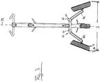
- a golf cart 10 is shown in principle, which has a frame 12 which in the exemplary embodiment consists of three frame parts, namely a lower frame part 14, a middle frame part 16 and one upper frame part 18.
- the frame parts 14, 16, 18 are, in particular from z. B. aluminum or high-strength steel existing tubular or square hollow sections which are connected to one another via joints 20, 22 and can be pivoted via the joints 20, 22. This creates the possibility that the frame parts 14, 16, 18 are folded to the extent that a compact unit results from the fact that the frame parts 14, 16, 18 lie on top of one another or are aligned parallel to one another, as in FIG Fig. 5 can be seen.
- a handle 24 extends from the upper frame part 18 and is composed of a base or middle section and angled end sections 28, 30. Of the Base section 26 is based on a receptacle 32 which can be inserted into and fixed in the upper frame part 18.
- the end sections 28, 30 have a course such that they run in the direction of a plane spanned by the frame 12, that is to say they extend towards one another, as the drawing shows. Furthermore, the end sections 28, 30 span a plane that includes an acute angle to the longitudinal axis 34 of the upper frame part 18. This results in an ergometric shape which leads to an actuation of the golf cart 10 which does not lead to fatigue.
- a first holder 36 for a golf bag extends from the proximal region of the middle frame part 16, that is to say the region adjoining the upper frame part 18.
- a second holder 38 extends from the distal region of the lower frame part 14, that is to say from the end which is distant in relation to the handle 24.
- a stop 40 runs between the holder 38 and the end of the lower frame part 14, which stop is designed to be pivotable and on which the bottom of a bag can be supported.
- a single front wheel 42 is connected to the lower frame part 14, specifically via a wheel support or a steering knuckle 44.
- the front wheel 24 is supported on one side, although preferably two-sided mounting should take place.
- the wheel 42 is preferably aligned with the lower frame part 14 in such a way that it is penetrated centrally by the longitudinal axis of the lower frame part.
- the running or rolling surface 41 of the front wheel 42 runs parallel to its axis.
- a cross member 46 which is connected via pivot / swivel joints 48, 50 to steering knuckles 52, 54, from which releasably extend side wheels 56, 58 which have a negative camber.
- This is formed in that the peripheral surface and thus the rolling or running or supporting surface 57, 59 of the wheels 56, 58 have the shape of a cone, as is self-explanatory from FIGS Figures can be seen and in particular also by the sectional view of a rim 60 according to Fig. 6 is conveyed.
- the sectional view shows the cone shape, the cone angle ⁇ being in the range between 20 ° and 40 ° and preferably 30 °.
- the longitudinal axis of the cone coincides with the axis of rotation of the respective wheel 56, 58.
- the axis of rotation should include an angle between 10 ° and 20 ° to the ground on which the golf cart 10 can be moved.
- a support 62 made of a suitable material such as plastic, rubber or rubber is then applied to the frustum of the cone of the rim 60 and can optionally be profiled. Regardless of this, a cone shape results which enables the desired negative camber of the wheels 56, 58.
- the negative camber results in particular in the advantage that the standing width of the golf cart 10 is relatively large, so that the golf cart 10 has a high stability.
- the wheels for folding the golf cart 10 can be detached from the steering knuckles 52, 54 without any problems.
- the rotary / swivel joints 48, 50 have surfaces lying one on top of the other, which run obliquely with respect to the plane spanned by the frame parts 14, 16, 18, as can be seen in particular from FIGS 3 - 5 results.
- the section of the support surfaces of the rotary / swivel joint 48, 50 is identified with the reference symbols 66, 68.
- a support or sliding surface is in Fig. 5 marked with 70.
- the superimposed surfaces thus run at an angle deviating from 90 ° to the horizontal when the golf cart 10 itself is parked on a horizontally running plane.
- the planes are penetrated perpendicularly by the axis about which the steering knuckle 52, 54 can be rotated.
- the planes are inclined to the horizontal in such a way that according to the representations according to Fig. 4 and 5 the steering knuckles 52, 54 can run parallel or approximately parallel to the frame part 16 when the golf cart 10 is folded.
- the steering knuckles 52, 54 are rotated about the axis passing through the rotary / swivel joints 48, 50, the steering knuckles 52, 54 are simultaneously moved in the direction of the central frame part 16 in order to, when folded, parallel to the frame parts 14, which run parallel to one another. 16, 18 to be aligned, as can be seen from the Fig. 4 and 5 results.
- the wheels 56, 58 are rotatable by means of pins or shaft stubs extending from the distal ends of the steering knuckles 52, 54, on which they can be locked.
- the golf cart 10 is movable by hand, i.e. usable without electric drive. It is also possible to design the golf cart 10 to be electrically driven. For this purpose, it is provided in particular that each side wheel 56, 58 is driven by a separate electric motor, which are electronically synchronized with one another.
Landscapes
- Engineering & Computer Science (AREA)
- Chemical & Material Sciences (AREA)
- Combustion & Propulsion (AREA)
- Transportation (AREA)
- Mechanical Engineering (AREA)
- Handcart (AREA)
Description
- Die Erfindung bezieht sich auf einen Golfwagen mit einem mehrteiligen Rahmen oder Gestell, umfassend zumindest ein oberes Rahmen- oder Gestellteil und ein zu diesem verschwenkbares unteres Rahmen- oder Gestellteil, von dem zwei verschwenkbare Achsschenkel mit mit diesen lösbar verbindbaren Seitenrädern ausgehen.
- Ein entsprechender Golfwagen ist z. B. der
DE 10 2008 045 104 A4 zu entnehmen. Der Golfwagen besteht aus drei als Rahmenstücke bezeichneten Gestellteile, die zueinander in einem Umfang verschwenkbar sind, dass die Rahmenstücke im zusammengeklappten Zustand des Golfwagens aufeinanderliegen, also etwa parallel zueinander ausgerichtet sind. Zum Zusammenklappen des Golfwagens sind die Achsschenkel zunächst nur in Richtung einer gedachten Aufstandsfläche der Räder gegenüber dem Rahmen verschwenkbar, um danach zur Positionierung im Wesentlichen parallel zu dem Rahmen verdreht zu werden. Zuvor können die Seitenräder entfernt werden. - In der
DE 200 19 137 U1 wird ein Golfwagen beschrieben, der vier Räder umfasst, und zwar zwei Seitenräder und zwei Vorderräder. Die Seitenräder sind mit dem Gestell des Golfwagens über Lagerstangen verbunden, die über parallelogrammartig wirkende Radtrag- oder Lagerstangen verbunden sind, um beim Zusammenklappen des Golfwagens diese zu dem Gestell auszurichten. - Seitenräder eines Golfwagens nach der
DE 20 2005 005 575 A1 sind über Dreh- / Schwenkgelenke mit dem Gestell des Golfwagens verbunden, um beim Zusammenlegen des Golfwagens die Gestellteile sowie die Achsschenkel parallel zueinander ausrichten zu können. - Ein zwei Seitenräder sowie ein Vorderrad aufweisender Golf-Caddy gemäß der
DE 20 2015 100 460 U1 hat im Rahmen Druckaktuatoren integriert, um ein Zusammenlegen zu erleichtern. - Die
US 2015/0028568 A1 sowie dieEP 2 907 554 A1 beziehen sich auf einen Golfwagen mit drei Rädern. - Ein dreirädriger Golfwagen ist auch der
US 2011/0285111 A1 zu entnehmen, dessen Räder ein Profil aufweisen, das im Schnitt eine Dachform aufweist. Ein entsprechendes Profil ist auch dem vier Räder aufweisenden Golfwagen nach derUS 2013/0062865 A1 zu entnehmen. - Der vorliegenden Erfindung liegt die Aufgabe zugrunde, einen Golfwagen der eingangs genannten Art so weiterzubilden, dass neben einer einfachen Handhabung sichergestellt ist, dass der Golfwagen bei Nutzung eine hohe Stabilität aufweist, im zusammengelegten Zustand jedoch überaus kompakt ist.
- Zur Lösung der Aufgabe sieht die Erfindung vor, dass die Seitenräder einen negativen Sturz besitzen, und dass die eine Lauffläche bildende Umfangsfläche jedes Seitenrades die Form eines Konus mit innenseitig geringerem Durchmesser als außenseitig aufweist, und dass jeder Achsschenkel entlang Innenseite des Seitenrades verläuft. Die Achse, um die jedes Seitenrad sich dreht, verläuft geneigt zu dem Untergrund, auf dem der Golfwagen verfahren wird.
- Durch die erfindungsgemäße Lehre ergibt sich die Möglichkeit, dass ungeachtet eines relativ geringen Abstandes der Achsschenkel eine hohe Standbreite erzielbar ist, da zum einen die Achsschenkel entlang den Innenseiten der Seitenräder verlaufen und zum anderen diese umfangsseitig die Form eines Konus aufweisen, wodurch sich ein negativer Sturz ergibt, so dass eine große Standfläche geboten wird. Dabei ist insbesondere vorgesehen, dass der Konus (s.
Fig. 6 ) einen Winkel α mit 20° ≤ α ≤ 40°, insbesondere α = 30° einschließt. Gegebenenfalls kann der Winkel auch eingestellt werden. - Die Breite A eines jeden Seitenrades, also die Länge bzw. maximaler Abstand, mit der das Rad auf einem Untergrund Kontakt hat, beläuft sich vorzugsweise zwischen75 mm und 105 mm.
- Der Außendurchmesser des Rades sollte zwischen 300 mm und 380 mm liegen.
- Der maximale Abstand S zwischen den Außenrändern der Seitenränder sollte betragen 800 mm ≤ S ≤ 880 mm.
- Durch die Abmessungen ergibt sich eine besonders gute Standfestigkeit.
- Um ein problemloses Ausrichten der Achsschenkel zu dem Rahmen oder Gestell - nachstehend aus Gründen der Einfachheit nur Gestell genannt - zu ermöglichen, sieht die Erfindung des Weiteren vor, dass jeder Achsschenkel über ein Dreh- / Schwenkgelenk mit dem unteren Gestellteil verbunden ist. Dreh- / Schwenkgelenk bedeutet dabei, dass beim Verschwenken der Achsschenkel gleichzeitig deren Abstand zueinander verringert wird, so dass ein vorzugsweise paralleles Ausrichten zu dem von dem unteren Gestellteil ausgehenden Gestellteil bei zusammengeklapptem Golfwagen gegeben ist. Dabei ist vorzugsweise vorgesehen, dass von dem unteren Gestellteil ein mittleres Gestellteil ausgeht, das gelenkig sowohl mit dem unteren Gestellteil als auch mit dem oberen Gestellteil verbunden ist.
- Das Dreh-/Schwenkgelenk wird dadurch realisiert, dass sich der Achsschenkel an einer schiefen Ebene abstützt, so dass ein Drehen gleichzeitig das gewünschte Schwenken bewirkt.
- Erfindungsgemäß ist insbesondere vorgesehen, dass bei zusammengeklapptem Golfwagen das untere und obere Gestellteil - bei Vorhandensein eines mittleren Gestellteils auch dieses -, sowie die Achsschenkel parallel oder im Wesentlichen parallel zueinander verlaufen.
- Von dem oberen Gestellteil geht ein vorzugsweise höhenverstellbarer Handgriff aus, der sich insbesondere dadurch auszeichnet, dass dieser aus einem quer zur von den Gestellteilen aufgespannten Ebene verlaufenden Mittelabschnitt und von dessen Enden ausgehenden Endabschnitten besteht, die ihrerseits mit ihren Enden einander zugewandt sind. Dabei kann der Handgriff eine Ebene aufspannen, die zur Längsachse des oberen Gestellteils einen spitzen Winkel einschließt. Durch die diesbezügliche Form ergibt sich eine vorteilhafte Ergonometrie, so dass das Schieben des Golfwagens nicht zu einer Ermüdung bzw. für das Golfspiel nachteilige Beanspruchung der Arme führt.
- Auch wenn der Golfwagen allein mit zwei Seitenrädern handhabbar wäre, ist insbesondere vorgesehen, dass vom distalen Bereich des unteren Gestellteils und einem mit diesem verbundenen Gestellteil ein Vorderrad ausgeht, das lösbar mit einem Achsschenkel verbunden sein kann, dessen Längsachse vorzugsweise parallel zur Längsachse des unteren Gestellteils verläuft. Somit ist der Golfwagen auf drei Rädern abstützbar. Die Roll- oder Fahrfläche, auch Abstützfläche genannt, des vorderen Rades verläuft parallel zu dessen Achse.
- Unabhängig hiervon sollten die zueinander verschwenkbaren Gestellteile durch Verrasten gegeneinander fixierbar sein. Dabei besteht die Möglichkeit, dass das den Handgriff aufweisende obere Gestellteil in unterschiedlichen Winkeln zu dem angrenzenden Gestellteil verrastbar ist. Unterschiedliches Verrasten schließt auch ein, dass zwischen den Gestellteilen ein Bauteil ausgetauscht wird, über das die gewünschte Winkelstellung ermöglicht wird, um den Golfwagen für Personen unterschiedlicher Größen nutzen zu können.
- Die Gestellteile werden im Wesentlichen durch Hohlprofile - insbesondere rohr- oder rechteckförmige Hohlprofile - gebildet, wobei jedes Gestellteil durch ein einziges Hohlprofil gebildet wird. Als Material wird insbesondere Aluminium oder höherfester Stahl oder anderes geeignetes Material verwendet. Die Enden der Hohlprofile weisen die Verbindungselemente einerseits zu angrenzenden Gestellteilen und andererseits zu dem Handgriff bzw. Achsschenkel für das Vorderrad auf.
- Des Weiteren geht von dem unteren Gestellteil ein Querholm aus, in dessen jeweiligem Endbereich das Dreh- / Schwenkgelenk verläuft, über das der jeweilige Achsschenkel mit dem Gestell verbunden wird.
- Um ein Golfbag aufzunehmen, können vom proximalen, also handgriffseitigen Bereich des oberen Gestellteils oder bei Vorhandensein eines mittleren Gestellteils von dessen proximalem Bereich und vom distalen Bereich des unteren Gestellteils jeweils eine Halterung ausgehen, wobei ergänzend im distalen Bereich des unteren Gestellteils ein von diesem abragender Anschlag ausgeht, der mit dem Boden eines Golfbags zusammenwirkt. Dieser Anschlag kann verstellbar bzw. verschwenkbar ausgebildet sein, um eine Anpassung an Golfbags unterschiedlicher Größen zu ermöglichen.
- Insbesondere ist die Erfindung gekennzeichnet durch einen Golfwagen mit einem mehrteiligen Rahmen oder Gestell umfassend zumindest ein oberes Rahmen- oder Gestellteil und ein zu diesem verschwenkbares unteres Rahmen- oder Gestellteil, von dem zwei verschwenkbare Achsschenkel mit mit diesen lösbar verbindbaren Seitenrädern ausgehen, wobei die Seitenräder einen negativen Sturz besitzen.
- Ein entsprechender Golfwagen ist auch durch Merkmale gekennzeichnet, wie diese zuvor erläutert worden sind bzw. sich aus dem Ausführungsbeispiel ergeben.
- Weitere Einzelheiten, Vorteile und Merkmale der Erfindung ergeben sich nicht nur aus den Ansprüchen, den diesen zu entnehmenden Merkmalen - für sich und/oder in Kombination - sondern auch aus der nachfolgenden Beschreibung eines der Zeichnungen zu entnehmenden bevorzugten Ausführungsbeispiels.
- Es zeigen:
- Fig. 1
- eine erste perspektivische Darstellung eines Golfwagens,
- Fig. 2
- eine weitere perspektivische Darstellung des Golfwagens gemäß
Fig. 1 , - Fig. 3
- der Golfwagen gemäß
Fig. 1 und2 , betrachtet von der Rückseite, - Fig. 4
- der Golfwagen gemäß
Fig. 1 bis 3 in Draufsicht in zusammengeklappter Stellung, - Fig. 5
- der Golfwagen gemäß
Fig. 1 bis 4 im zusammengeklappten Zustand in seitlicher Ansicht und - Fig. 6
- im Schnitt eine Felge eines Seitenrades des Golfwagens der
Fig. 1 - 5 . - In den Figuren, in denen grundsätzlich für gleiche Elemente gleiche Bezugszeichen verwendet werden, ist ein Golfwagen 10 rein prinzipiell dargestellt, der ein Gestell 12 aufweist, das im Ausführungsbeispiel aus drei Gestellteilen besteht, und zwar einem unteren Gestellteil 14, einem mittleren Gestellteil 16 und einem oberen Gestellteil 18. Bei den Gestellteilen 14, 16, 18 handelt es sich um insbesondere aus z. B. Aluminium oder höherfestem Stahl bestehende rohr- bzw. vierkantförmige Hohlprofile, die über Gelenke 20, 22 miteinander verbunden und über die Gelenke 20, 22 verschwenkbar sind. Hierdurch wird die Möglichkeit geschaffen, dass die Gestellteile 14, 16, 18 in einem Umfang zusammengeklappt werden, dass sich eine kompakte Einheit dadurch ergibt, dass die Gestellteile 14, 16, 18 aufeinanderliegen bzw. parallel zueinander ausgerichtet sind, wie der
Fig. 5 zu entnehmen ist. - Im aufgestellten Zustand sind die Gestellteile 14, 16, 18 zueinander verrastet, so dass ein unkontrolliertes Verschwenken nicht möglich ist. Erst durch Lösen einer Arretierung mittels z. B. eines Druckknopfs besteht die Möglichkeit, die Verrastung aufzuheben, um somit die Gestellteile 14, 16, 18 zueinander zu verschwenken.
- Von dem oberen Gestellteil 18 geht ein Handgriff 24 aus, der sich aus einem Basis- oder Mittelabschnitt und abgewinkelten Endabschnitten 28, 30 zusammensetzt. Der Basisabschnitt 26 geht von einer Aufnahme 32 aus, die in das obere Gestellteil 18 einschiebbar und in diesem fixierbar ist.
- Die Endabschnitte 28, 30 haben einen Verlauf derart, dass diese in Richtung einer von dem Gestell 12 aufgespannten Ebene verlaufen, also aufeinander zu gerichtet sich erstrecken, wie die zeichnerische Darstellung vermittelt. Des Weiteren spannen die Endabschnitte 28, 30 eine Ebene auf, die einen spitzen Winkel zur Längsachse 34 des oberen Gestellteils 18 einschließt. Hierdurch ergibt sich eine ergometrische Form, die ein zur Ermüdung nicht führendes Betätigen des Golfwagens 10 führt.
- Vom proximalen Bereich des mittleren Gestellteils 16, also dem an dem oberen Gestellteil 18 angrenzenden Bereich, geht eine erste Halterung 36 für ein Golfbag aus. Eine zweite Halterung 38 geht vom distalen Bereich des unteren Gestellteils 14 aus, also von dem in Bezug auf den Handgriff 24 entfernt liegenden Ende. Ferner verläuft zwischen der Halterung 38 und dem Ende des unteren Gestellteils 14 ein Anschlag 40, der verschwenkbar ausgebildet ist und an dem sich der Boden eines Bags abstützen kann.
- Mit dem unteren Gestellteil 14 ist insbesondere ein einziges Vorderrad 42 verbunden, und zwar über eine Radstütze bzw. einen Achsschenkel 44. Dabei wird im Ausführungsbeispiel das Vorderrad 24 einseitig gelagert, gleichwenn bevorzugterweise eine zweiseitige Lagerung erfolgen sollte. Das Rad 42 ist dabei vorzugsweise derart zu dem unteren Gestellteil 14 ausgerichtet, dass dieses von der Längsachse des unteren Gestellteils mittig durchsetzt wird.
- Die Lauf- oder Rollfläche 41 des Vorderrads 42 verläuft parallel zu dessen Achse.
- Von dem unteren Gestellteil 14 geht des Weiteren ein Querholm 46 aus, der über Dreh-/Schwenkgelenke 48, 50 mit Achsschenkeln 52, 54 verbunden ist, von denen lösbar Seitenräder 56, 58 ausgehen, die einen negativen Sturz besitzen. Dieser wird dadurch gebildet, dass die Umfangsfläche und damit die Abroll- oder Lauf- oder Abstützfläche 57, 59 der Räder 56, 58 die Form eines Konus aufweisen, wie selbsterklärend aus den Figuren ersichtlich ist und insbesondere auch durch die Schnittdarstellung einer Felge 60 gemäß
Fig. 6 vermittelt wird. Die Schnittdarstellung zeigt die Konusform, wobei der Konuswinkel α im Bereich zwischen 20° und 40° und bevorzugterweise bei 30° liegt. - Die Längsachse des Konus fällt mit der Drehachse des jeweiligen Rades 56, 58 zusammen. Die Drehachse sollte einen Winkel zwischen 10° und 20° zum Untergrund einschließen, auf dem der Golfwagen 10 verfahrbar ist.
- Auf der Kegelstumpfumfangsfläche der Felge 60 ist sodann eine aus geeignetem Material wie Kunststoff, Gummi oder Kautschuk bestehende Auflage 62 aufgebracht, die gegebenenfalls profiliert sein kann. Ungeachtet dessen ergibt sich eine Konusform, die den gewünschten negativen Sturz der Räder 56, 58 ermöglicht.
- Auch wenn die Achsschenkel 52, 54 innenseitig entlang der Räder 56, 58 verlaufen, also die Achsschenkel 52 ,54 einen nicht sehr großen Abstand aufweisen, ergibt sich durch den negativen Sturz insbesondere der Vorteil, dass die Standbreite des Golfwagens 10 relativ groß ist, so dass der Golfwagen 10 eine hohe Stabilität besitzt. Außerdem ergibt sich der Vorteil, dass die Räder zum Zusammenklappen des Golfwagens 10 problemlos von den Achsschenkeln 52, 54 gelöst werden können.
- Die Dreh-/Schwenkgelenke 48, 50 weisen aufeinander liegende Flächen auf, die in Bezug auf die von den Gestellteilen 14, 16, 18 aufgespannte Ebene schräg verlaufen, wie sich insbesondere aus den
Fig. 3 - 5 ergibt. In dieser ist der Schnitt der Abstützflächen des Dreh-/Schwenkgelenks 48, 50 mit den Bezugszeichen 66, 68 gekennzeichnet. Eine Abstütz- bzw. Gleitfläche ist inFig. 5 mit 70 gekennzeichnet. - Die aufeinanderliegenden Flächen verlaufen somit unter einem von 90° abweichenden Winkel zur Horizontalen, wenn der Golfwagen 10 selbst auf einer horizontal verlaufenden Ebene abgestellt ist. Die Ebenen werden senkrecht von der Achse durchsetzt, um die die Achsschenkel 52, 54 drehbar ist. Dabei sind die Ebenen derart zur Horizontalen geneigt, dass entsprechend den Darstellungen gemäß der
Fig. 4 und5 die Achsschenkel 52, 54 bei zusammengelegtem Golfwagen 10 parallel oder in etwa parallel zu dem Gestellteil 16 verlaufen können. - Werden die Achsschenkel 52, 54 um die die Dreh-/Schwenkgelenke 48, 50 durchsetzende Achse gedreht, so erfolgt gleichzeitig ein Bewegen der Achsschenkel 52, 54 in Richtung des mittleren Gestellteils 16, um im zusammengeklappten Zustand parallel zu den parallel zueinander verlaufenden Gestellteilen 14, 16, 18 ausgerichtet zu sein, wie sich aus den
Fig. 4 und5 ergibt. - Wie sich aus den
Fig. 4 und5 des Weiteren ergibt, sind die Räder 56, 58 um durch von distalen Enden der Achsschenkel 52, 54 ausgehende Zapfen oder Wellenstümpfe drehbar, auf dem diese verrastbar sind. - Der Golfwagen 10 ist von Hand verfahrbar, d.h. ohne elektrischen Antrieb nutzbar. Es besteht auch die Möglichkeit, den Golfwagen 10 elektrisch angetrieben auszubilden. Hierzu ist insbesondere vorgesehen, dass jedes Seitenrad 56, 58 über einen gesonderten Elektromotor angetrieben wird, die untereinander elektronisch synchronisiert sind.
Claims (15)
- Golfwagen (10) mit einem mehrteiligen Rahmen oder Gestell umfassend zumindest ein oberes Rahmen- oder Gestellteil (18) und ein zu diesem verschwenkbares unteres Rahmen- oder Gestellteil (14), von dem zwei verschwenkbare Achsschenkel (52, 54) mit mit diesen lösbar verbindbaren Seitenrädern (56, 58) ausgehen,
dadurch gekennzeichnet,
dass die Seitenräder (56, 58) einen negativen Sturz besitzen, und
dass die eine Lauffläche bildende Umfangsfläche jedes Seitenrades (56, 58) die Form eines Konus mit innenseitig geringerem Durchmesser als außenseitig aufweist, und dass jeder Achsschenkel (52, 54) entlang Innenseite des Seitenrades verläuft. - Golfwagen nach Anspruch 1,
dadurch gekennzeichnet,
dass der Konus einen Winkel α mit 20° ≤ α ≤ 40°, insbesondere α = 30° einschließt, wobei gegebenenfalls der Konus verstellbar ist. - Golfwagen nach Anspruch 1 oder 2,
dadurch gekennzeichnet,
dass bei zusammengeklapptem Golfwagen (10) das untere und obere Rahmen- oder Gestellteil (14, 18) sowie die Achsschenkel (52, 54) parallel oder im Wesentlichen parallel zueinander verlaufen. - Golfwagen nach zumindest einem der vorhergehenden Ansprüche,
dadurch gekennzeichnet,
dass von dem oberen Rahmen- oder Gestellteil (18) ein höhenverstellbarer Handgriff (24) ausgeht, wobei vorzugsweise das den Handgriff (24) aufweisende obere Rahmen- oder Gestellteil (18) in unterschiedlichen Winkeln zu dem angrenzenden Rahmen- oder Gestellteil (16) fixierbar ist. - Golfwagen nach zumindest einem der vorhergehenden Ansprüche,
dadurch gekennzeichnet,
dass zwischen dem unteren und dem oberen Rahmen- oder Gestellteil (14, 18) ein zu diesen verschwenkbares mittleres Rahmen- oder Gestellteil (16) verläuft. - Golfwagen nach zumindest einem der vorhergehenden Ansprüche,
dadurch gekennzeichnet,
dass vom distalen Bereich des unteren Rahmen- oder Gestellteils (14) ein Vorderrad (42) ausgeht, das gegebenenfalls lösbar mit einem Achsschenkel (44) verbunden ist. - Golfwagen nach zumindest einem der vorhergehenden Ansprüche,
dadurch gekennzeichnet,
dass die Längsachse des unteren Rahmen- oder Gestellteils (14) mittig das Vorderrad (42) durchsetzt. - Golfwagen nach zumindest Anspruch 1,
dadurch gekennzeichnet,
dass jeder Achsschenkel (52, 54) über ein Dreh-Schwenkgelenk (48, 50) mit dem unteren Rahmen- oder Gestellteil (14) verbunden ist, dass das Dreh-Schwenkgelenk (48, 50) aufeinanderliegende Flächen aufweist, die in Bezug auf eine von den Gestellteilen (12, 14, 16) aufgespannten Ebene schräg verlaufen derart, dass beim Verschwenken des Achsschenkels (52, 54) in Richtung des Rahmens oder Gestells (12) seitlicher Abstand des Achsschenkels zu dem Rahmen oder Gestell abnimmt. - Golfwagen nach zumindest einem der vorhergehenden Ansprüche,
dadurch gekennzeichnet,
dass die Rahmen- oder Gestellteile (14, 16, 18) durch Verrastung gegeneinander fixierbar sind. - Golfwagen nach zumindest einem der vorhergehenden Ansprüche,
dadurch gekennzeichnet,
dass der Handgriff (24) einen quer, insbesondere senkrecht, zur von dem Rahmen- oder Gestell (12) aufgespannten Ebene verlaufenden Basisabschnitt (26) und von dessen Enden ausgehende Endabschnitte (28, 30) umfasst, die jeweils mit ihren Enden einander zugewandt sind, wobei die Endabschnitte (28, 30) eine Ebene aufspannen, die zur Längsachse (34) des oberen Rahmen- oder Gestellteils (18) einen spitzen Winkel einschließt. - Golfwagen nach zumindest einem der vorhergehenden Ansprüche,
dadurch gekennzeichnet,
dass jedes Rahmen- oder Gestellteil (14, 16, 18) durch oder im Wesentlichen durch ein insbesondere rechteckförmiges Hohlprofil, insbesondere aus Aluminium, gebildet ist. - Golfwagen nach zumindest einem der vorhergehenden Ansprüche,
dadurch gekennzeichnet,
dass von dem unteren Rahmen- oder Gestellteil (14) ein Querholm (46) ausgeht, in dessen jeweiligem Endbereich das Dreh-Schwenkgelenk (48, 50) verläuft. - Golfwagen nach zumindest einem der vorhergehenden Ansprüche,
dadurch gekennzeichnet,
dass vom proximalen Bereich des unteren Rahmen- oder Gestellteils (14) der Querholm (46) ausgeht. - Golfwagen nach zumindest einem der vorhergehenden Ansprüche,
dadurch gekennzeichnet,
dass vom proximalen Bereich des mittleren Rahmen- oder Gestellteils (16) und vom distalen Bereich des unteren Rahmen- oder Gestellteils (14) eine Halterung (36, 38) ausgeht. - Golfwagen nach zumindest einem der vorhergehenden Ansprüche,
dadurch gekennzeichnet,
dass zwischen der von dem unteren Rahmen- oder Gestellteil (14) ausgehenden Halterung (38) und dem Vorderrad (42) ein vorzugsweise verstellbarer Anschlag (40) verläuft.
Applications Claiming Priority (1)
| Application Number | Priority Date | Filing Date | Title |
|---|---|---|---|
| DE202015104209.4U DE202015104209U1 (de) | 2015-08-11 | 2015-08-11 | Golfwagen |
Publications (2)
| Publication Number | Publication Date |
|---|---|
| EP3132990A1 EP3132990A1 (de) | 2017-02-22 |
| EP3132990B1 true EP3132990B1 (de) | 2020-03-25 |
Family
ID=56682006
Family Applications (1)
| Application Number | Title | Priority Date | Filing Date |
|---|---|---|---|
| EP16183616.8A Active EP3132990B1 (de) | 2015-08-11 | 2016-08-10 | Golfwagen |
Country Status (2)
| Country | Link |
|---|---|
| EP (1) | EP3132990B1 (de) |
| DE (1) | DE202015104209U1 (de) |
Family Cites Families (13)
| Publication number | Priority date | Publication date | Assignee | Title |
|---|---|---|---|---|
| DE3714066A1 (de) * | 1986-08-12 | 1988-02-18 | Otto Oeckl | Golfausruestung |
| DE9415259U1 (de) * | 1994-09-20 | 1994-11-17 | Cheng, Ying-Hsiung, Jen Te Hsiang, Tainan | Zusammenlegbarer Golfwagen |
| CA2313591C (en) * | 2000-07-05 | 2007-08-21 | Unique Product & Design Co., Ltd. | Wheel supporter and shaft for a golf cart |
| GB0022104D0 (en) * | 2000-09-08 | 2000-10-25 | Crisp David | Collapsible pushchair/carrier |
| DE20019137U1 (de) | 2000-11-10 | 2001-01-11 | Unique Product & Design Co., Ltd., Yung Kang, Tainan | Golfwagen |
| DE202005005575U1 (de) | 2005-04-07 | 2006-08-17 | Laurer, Stefan | Golfwagen |
| DE102008045104B4 (de) | 2008-08-29 | 2014-03-13 | Norbert Pietsch | Zusammenklappbarer Golfwagen |
| IT1399683B1 (it) * | 2010-03-29 | 2013-04-26 | Mondo Spa | Monopattino |
| US8292321B2 (en) * | 2010-05-21 | 2012-10-23 | Unique Product & Design Co., Ltd. | Golf bag cart foldable device |
| US8480098B2 (en) * | 2011-09-09 | 2013-07-09 | Unique Product & Design Co., Ltd. | Golf bag cart |
| CN202822656U (zh) * | 2012-10-12 | 2013-03-27 | 宁波稳泰运动器材有限公司 | 一种改进型高尔夫球车 |
| US9162695B2 (en) * | 2013-07-24 | 2015-10-20 | Thinh Tran | Collapsible three-wheeled all-in-one golf cart |
| DE202015100460U1 (de) | 2015-01-30 | 2015-05-13 | Günther Bausch | Golfcaddy |
-
2015
- 2015-08-11 DE DE202015104209.4U patent/DE202015104209U1/de not_active Expired - Lifetime
-
2016
- 2016-08-10 EP EP16183616.8A patent/EP3132990B1/de active Active
Non-Patent Citations (1)
| Title |
|---|
| None * |
Also Published As
| Publication number | Publication date |
|---|---|
| EP3132990A1 (de) | 2017-02-22 |
| DE202015104209U1 (de) | 2016-11-15 |
Similar Documents
| Publication | Publication Date | Title |
|---|---|---|
| EP2954938B1 (de) | Klappbarer tretroller mit gepäckträger | |
| EP0645296B1 (de) | Handwagen nach Art eines Leiterwagens | |
| EP3030471B1 (de) | Zusammenlegbarer transportwagen | |
| WO2014009143A1 (de) | Motorisiertes dreirädriges golf-trolley | |
| EP3442724B1 (de) | Verfahren und vorrichtung zum richten eines werkstücks | |
| DE10147400A1 (de) | Sackkarren | |
| DE102014110261A1 (de) | Lastenfahrrad | |
| EP2921151B1 (de) | Mobilitätshilfe | |
| CH617133A5 (de) | ||
| DE202016103587U1 (de) | Doppelkeilradsperre | |
| EP3132990B1 (de) | Golfwagen | |
| WO2018108346A1 (de) | Lenkeinheit für ein fahrzeug und fahrzeug, insbesondere elektroroller | |
| DE102008045104B4 (de) | Zusammenklappbarer Golfwagen | |
| AT515074A1 (de) | Roller | |
| DE102014222149B4 (de) | Klappfahrrad | |
| EP3449795A1 (de) | Flächenbearbeitungsgerät | |
| DE4326786B4 (de) | Kipp-Wagenheber | |
| DE102012208048B3 (de) | Golfcaddy | |
| DE102005010511B4 (de) | Einkaufswagen | |
| DE112011103940B4 (de) | Golfwagen | |
| EP3378754B1 (de) | Fahrradanhänger mit verschwenkbarer deichsel | |
| DE102007001122B3 (de) | Transportwagen | |
| DE512616C (de) | Gleitschutz fuer Kraftfahrzeugraeder | |
| EP2759455A2 (de) | Rollwagen für eine Maschine, insbesondere eine Baumaschine | |
| DE19636516A1 (de) | Zusammenlegbarer Zweiradrahmen |
Legal Events
| Date | Code | Title | Description |
|---|---|---|---|
| PUAI | Public reference made under article 153(3) epc to a published international application that has entered the european phase |
Free format text: ORIGINAL CODE: 0009012 |
|
| STAA | Information on the status of an ep patent application or granted ep patent |
Free format text: STATUS: THE APPLICATION HAS BEEN PUBLISHED |
|
| AK | Designated contracting states |
Kind code of ref document: A1 Designated state(s): AL AT BE BG CH CY CZ DE DK EE ES FI FR GB GR HR HU IE IS IT LI LT LU LV MC MK MT NL NO PL PT RO RS SE SI SK SM TR |
|
| AX | Request for extension of the european patent |
Extension state: BA ME |
|
| STAA | Information on the status of an ep patent application or granted ep patent |
Free format text: STATUS: REQUEST FOR EXAMINATION WAS MADE |
|
| 17P | Request for examination filed |
Effective date: 20170822 |
|
| RBV | Designated contracting states (corrected) |
Designated state(s): AL AT BE BG CH CY CZ DE DK EE ES FI FR GB GR HR HU IE IS IT LI LT LU LV MC MK MT NL NO PL PT RO RS SE SI SK SM TR |
|
| GRAP | Despatch of communication of intention to grant a patent |
Free format text: ORIGINAL CODE: EPIDOSNIGR1 |
|
| STAA | Information on the status of an ep patent application or granted ep patent |
Free format text: STATUS: GRANT OF PATENT IS INTENDED |
|
| INTG | Intention to grant announced |
Effective date: 20190604 |
|
| GRAS | Grant fee paid |
Free format text: ORIGINAL CODE: EPIDOSNIGR3 |
|
| GRAJ | Information related to disapproval of communication of intention to grant by the applicant or resumption of examination proceedings by the epo deleted |
Free format text: ORIGINAL CODE: EPIDOSDIGR1 |
|
| GRAL | Information related to payment of fee for publishing/printing deleted |
Free format text: ORIGINAL CODE: EPIDOSDIGR3 |
|
| STAA | Information on the status of an ep patent application or granted ep patent |
Free format text: STATUS: REQUEST FOR EXAMINATION WAS MADE |
|
| INTC | Intention to grant announced (deleted) | ||
| GRAP | Despatch of communication of intention to grant a patent |
Free format text: ORIGINAL CODE: EPIDOSNIGR1 |
|
| STAA | Information on the status of an ep patent application or granted ep patent |
Free format text: STATUS: GRANT OF PATENT IS INTENDED |
|
| GRAA | (expected) grant |
Free format text: ORIGINAL CODE: 0009210 |
|
| STAA | Information on the status of an ep patent application or granted ep patent |
Free format text: STATUS: THE PATENT HAS BEEN GRANTED |
|
| INTG | Intention to grant announced |
Effective date: 20200128 |
|
| AK | Designated contracting states |
Kind code of ref document: B1 Designated state(s): AL AT BE BG CH CY CZ DE DK EE ES FI FR GB GR HR HU IE IS IT LI LT LU LV MC MK MT NL NO PL PT RO RS SE SI SK SM TR |
|
| REG | Reference to a national code |
Ref country code: GB Ref legal event code: FG4D Free format text: NOT ENGLISH |
|
| REG | Reference to a national code |
Ref country code: AT Ref legal event code: REF Ref document number: 1248249 Country of ref document: AT Kind code of ref document: T Effective date: 20200415 Ref country code: IE Ref legal event code: FG4D Free format text: LANGUAGE OF EP DOCUMENT: GERMAN |
|
| REG | Reference to a national code |
Ref country code: DE Ref legal event code: R096 Ref document number: 502016009243 Country of ref document: DE |
|
| REG | Reference to a national code |
Ref country code: CH Ref legal event code: NV Representative=s name: LUCHS AND PARTNER AG PATENTANWAELTE, CH |
|
| PG25 | Lapsed in a contracting state [announced via postgrant information from national office to epo] |
Ref country code: NO Free format text: LAPSE BECAUSE OF FAILURE TO SUBMIT A TRANSLATION OF THE DESCRIPTION OR TO PAY THE FEE WITHIN THE PRESCRIBED TIME-LIMIT Effective date: 20200625 Ref country code: FI Free format text: LAPSE BECAUSE OF FAILURE TO SUBMIT A TRANSLATION OF THE DESCRIPTION OR TO PAY THE FEE WITHIN THE PRESCRIBED TIME-LIMIT Effective date: 20200325 Ref country code: RS Free format text: LAPSE BECAUSE OF FAILURE TO SUBMIT A TRANSLATION OF THE DESCRIPTION OR TO PAY THE FEE WITHIN THE PRESCRIBED TIME-LIMIT Effective date: 20200325 |
|
| PG25 | Lapsed in a contracting state [announced via postgrant information from national office to epo] |
Ref country code: BG Free format text: LAPSE BECAUSE OF FAILURE TO SUBMIT A TRANSLATION OF THE DESCRIPTION OR TO PAY THE FEE WITHIN THE PRESCRIBED TIME-LIMIT Effective date: 20200625 Ref country code: SE Free format text: LAPSE BECAUSE OF FAILURE TO SUBMIT A TRANSLATION OF THE DESCRIPTION OR TO PAY THE FEE WITHIN THE PRESCRIBED TIME-LIMIT Effective date: 20200325 Ref country code: LV Free format text: LAPSE BECAUSE OF FAILURE TO SUBMIT A TRANSLATION OF THE DESCRIPTION OR TO PAY THE FEE WITHIN THE PRESCRIBED TIME-LIMIT Effective date: 20200325 Ref country code: GR Free format text: LAPSE BECAUSE OF FAILURE TO SUBMIT A TRANSLATION OF THE DESCRIPTION OR TO PAY THE FEE WITHIN THE PRESCRIBED TIME-LIMIT Effective date: 20200626 Ref country code: HR Free format text: LAPSE BECAUSE OF FAILURE TO SUBMIT A TRANSLATION OF THE DESCRIPTION OR TO PAY THE FEE WITHIN THE PRESCRIBED TIME-LIMIT Effective date: 20200325 |
|
| REG | Reference to a national code |
Ref country code: NL Ref legal event code: MP Effective date: 20200325 |
|
| REG | Reference to a national code |
Ref country code: LT Ref legal event code: MG4D |
|
| PG25 | Lapsed in a contracting state [announced via postgrant information from national office to epo] |
Ref country code: NL Free format text: LAPSE BECAUSE OF FAILURE TO SUBMIT A TRANSLATION OF THE DESCRIPTION OR TO PAY THE FEE WITHIN THE PRESCRIBED TIME-LIMIT Effective date: 20200325 |
|
| PG25 | Lapsed in a contracting state [announced via postgrant information from national office to epo] |
Ref country code: CZ Free format text: LAPSE BECAUSE OF FAILURE TO SUBMIT A TRANSLATION OF THE DESCRIPTION OR TO PAY THE FEE WITHIN THE PRESCRIBED TIME-LIMIT Effective date: 20200325 Ref country code: IS Free format text: LAPSE BECAUSE OF FAILURE TO SUBMIT A TRANSLATION OF THE DESCRIPTION OR TO PAY THE FEE WITHIN THE PRESCRIBED TIME-LIMIT Effective date: 20200725 Ref country code: SK Free format text: LAPSE BECAUSE OF FAILURE TO SUBMIT A TRANSLATION OF THE DESCRIPTION OR TO PAY THE FEE WITHIN THE PRESCRIBED TIME-LIMIT Effective date: 20200325 Ref country code: SM Free format text: LAPSE BECAUSE OF FAILURE TO SUBMIT A TRANSLATION OF THE DESCRIPTION OR TO PAY THE FEE WITHIN THE PRESCRIBED TIME-LIMIT Effective date: 20200325 Ref country code: EE Free format text: LAPSE BECAUSE OF FAILURE TO SUBMIT A TRANSLATION OF THE DESCRIPTION OR TO PAY THE FEE WITHIN THE PRESCRIBED TIME-LIMIT Effective date: 20200325 Ref country code: RO Free format text: LAPSE BECAUSE OF FAILURE TO SUBMIT A TRANSLATION OF THE DESCRIPTION OR TO PAY THE FEE WITHIN THE PRESCRIBED TIME-LIMIT Effective date: 20200325 Ref country code: PT Free format text: LAPSE BECAUSE OF FAILURE TO SUBMIT A TRANSLATION OF THE DESCRIPTION OR TO PAY THE FEE WITHIN THE PRESCRIBED TIME-LIMIT Effective date: 20200818 Ref country code: LT Free format text: LAPSE BECAUSE OF FAILURE TO SUBMIT A TRANSLATION OF THE DESCRIPTION OR TO PAY THE FEE WITHIN THE PRESCRIBED TIME-LIMIT Effective date: 20200325 |
|
| REG | Reference to a national code |
Ref country code: DE Ref legal event code: R097 Ref document number: 502016009243 Country of ref document: DE |
|
| PG25 | Lapsed in a contracting state [announced via postgrant information from national office to epo] |
Ref country code: IT Free format text: LAPSE BECAUSE OF FAILURE TO SUBMIT A TRANSLATION OF THE DESCRIPTION OR TO PAY THE FEE WITHIN THE PRESCRIBED TIME-LIMIT Effective date: 20200325 Ref country code: DK Free format text: LAPSE BECAUSE OF FAILURE TO SUBMIT A TRANSLATION OF THE DESCRIPTION OR TO PAY THE FEE WITHIN THE PRESCRIBED TIME-LIMIT Effective date: 20200325 Ref country code: ES Free format text: LAPSE BECAUSE OF FAILURE TO SUBMIT A TRANSLATION OF THE DESCRIPTION OR TO PAY THE FEE WITHIN THE PRESCRIBED TIME-LIMIT Effective date: 20200325 |
|
| PLBE | No opposition filed within time limit |
Free format text: ORIGINAL CODE: 0009261 |
|
| STAA | Information on the status of an ep patent application or granted ep patent |
Free format text: STATUS: NO OPPOSITION FILED WITHIN TIME LIMIT |
|
| PG25 | Lapsed in a contracting state [announced via postgrant information from national office to epo] |
Ref country code: PL Free format text: LAPSE BECAUSE OF FAILURE TO SUBMIT A TRANSLATION OF THE DESCRIPTION OR TO PAY THE FEE WITHIN THE PRESCRIBED TIME-LIMIT Effective date: 20200325 |
|
| 26N | No opposition filed |
Effective date: 20210112 |
|
| PG25 | Lapsed in a contracting state [announced via postgrant information from national office to epo] |
Ref country code: MC Free format text: LAPSE BECAUSE OF FAILURE TO SUBMIT A TRANSLATION OF THE DESCRIPTION OR TO PAY THE FEE WITHIN THE PRESCRIBED TIME-LIMIT Effective date: 20200325 |
|
| GBPC | Gb: european patent ceased through non-payment of renewal fee |
Effective date: 20200810 |
|
| PG25 | Lapsed in a contracting state [announced via postgrant information from national office to epo] |
Ref country code: LU Free format text: LAPSE BECAUSE OF NON-PAYMENT OF DUE FEES Effective date: 20200810 |
|
| REG | Reference to a national code |
Ref country code: BE Ref legal event code: MM Effective date: 20200831 |
|
| PG25 | Lapsed in a contracting state [announced via postgrant information from national office to epo] |
Ref country code: SI Free format text: LAPSE BECAUSE OF FAILURE TO SUBMIT A TRANSLATION OF THE DESCRIPTION OR TO PAY THE FEE WITHIN THE PRESCRIBED TIME-LIMIT Effective date: 20200325 |
|
| PG25 | Lapsed in a contracting state [announced via postgrant information from national office to epo] |
Ref country code: FR Free format text: LAPSE BECAUSE OF NON-PAYMENT OF DUE FEES Effective date: 20200831 |
|
| PG25 | Lapsed in a contracting state [announced via postgrant information from national office to epo] |
Ref country code: BE Free format text: LAPSE BECAUSE OF NON-PAYMENT OF DUE FEES Effective date: 20200831 Ref country code: IE Free format text: LAPSE BECAUSE OF NON-PAYMENT OF DUE FEES Effective date: 20200810 Ref country code: GB Free format text: LAPSE BECAUSE OF NON-PAYMENT OF DUE FEES Effective date: 20200810 |
|
| PG25 | Lapsed in a contracting state [announced via postgrant information from national office to epo] |
Ref country code: TR Free format text: LAPSE BECAUSE OF FAILURE TO SUBMIT A TRANSLATION OF THE DESCRIPTION OR TO PAY THE FEE WITHIN THE PRESCRIBED TIME-LIMIT Effective date: 20200325 Ref country code: MT Free format text: LAPSE BECAUSE OF FAILURE TO SUBMIT A TRANSLATION OF THE DESCRIPTION OR TO PAY THE FEE WITHIN THE PRESCRIBED TIME-LIMIT Effective date: 20200325 Ref country code: CY Free format text: LAPSE BECAUSE OF FAILURE TO SUBMIT A TRANSLATION OF THE DESCRIPTION OR TO PAY THE FEE WITHIN THE PRESCRIBED TIME-LIMIT Effective date: 20200325 |
|
| PG25 | Lapsed in a contracting state [announced via postgrant information from national office to epo] |
Ref country code: MK Free format text: LAPSE BECAUSE OF FAILURE TO SUBMIT A TRANSLATION OF THE DESCRIPTION OR TO PAY THE FEE WITHIN THE PRESCRIBED TIME-LIMIT Effective date: 20200325 Ref country code: AL Free format text: LAPSE BECAUSE OF FAILURE TO SUBMIT A TRANSLATION OF THE DESCRIPTION OR TO PAY THE FEE WITHIN THE PRESCRIBED TIME-LIMIT Effective date: 20200325 |
|
| PGFP | Annual fee paid to national office [announced via postgrant information from national office to epo] |
Ref country code: DE Payment date: 20220825 Year of fee payment: 7 Ref country code: AT Payment date: 20220822 Year of fee payment: 7 |
|
| PGFP | Annual fee paid to national office [announced via postgrant information from national office to epo] |
Ref country code: CH Payment date: 20220824 Year of fee payment: 7 |
|
| REG | Reference to a national code |
Ref country code: DE Ref legal event code: R119 Ref document number: 502016009243 Country of ref document: DE |
|
| REG | Reference to a national code |
Ref country code: CH Ref legal event code: PL |
|
| REG | Reference to a national code |
Ref country code: AT Ref legal event code: MM01 Ref document number: 1248249 Country of ref document: AT Kind code of ref document: T Effective date: 20230810 |
|
| PG25 | Lapsed in a contracting state [announced via postgrant information from national office to epo] |
Ref country code: AT Free format text: LAPSE BECAUSE OF NON-PAYMENT OF DUE FEES Effective date: 20230810 |
|
| PG25 | Lapsed in a contracting state [announced via postgrant information from national office to epo] |
Ref country code: AT Free format text: LAPSE BECAUSE OF NON-PAYMENT OF DUE FEES Effective date: 20230810 Ref country code: CH Free format text: LAPSE BECAUSE OF NON-PAYMENT OF DUE FEES Effective date: 20230831 |
|
| PG25 | Lapsed in a contracting state [announced via postgrant information from national office to epo] |
Ref country code: DE Free format text: LAPSE BECAUSE OF NON-PAYMENT OF DUE FEES Effective date: 20240301 |