EP2954960B1 - Dispositif de désinfection et de nettoyage de tuyaux, en particulier de conduites d'eau potable et procédé de désinfection et de nettoyage de telles conduites - Google Patents
Dispositif de désinfection et de nettoyage de tuyaux, en particulier de conduites d'eau potable et procédé de désinfection et de nettoyage de telles conduites Download PDFInfo
- Publication number
- EP2954960B1 EP2954960B1 EP15001686.3A EP15001686A EP2954960B1 EP 2954960 B1 EP2954960 B1 EP 2954960B1 EP 15001686 A EP15001686 A EP 15001686A EP 2954960 B1 EP2954960 B1 EP 2954960B1
- Authority
- EP
- European Patent Office
- Prior art keywords
- container
- chemical
- connecting piece
- pipe coupling
- cleaning
- Prior art date
- Legal status (The legal status is an assumption and is not a legal conclusion. Google has not performed a legal analysis and makes no representation as to the accuracy of the status listed.)
- Active
Links
Images

Classifications
-
- B—PERFORMING OPERATIONS; TRANSPORTING
- B08—CLEANING
- B08B—CLEANING IN GENERAL; PREVENTION OF FOULING IN GENERAL
- B08B9/00—Cleaning hollow articles by methods or apparatus specially adapted thereto
- B08B9/02—Cleaning pipes or tubes or systems of pipes or tubes
- B08B9/027—Cleaning the internal surfaces; Removal of blockages
- B08B9/032—Cleaning the internal surfaces; Removal of blockages by the mechanical action of a moving fluid, e.g. by flushing
- B08B9/0321—Cleaning the internal surfaces; Removal of blockages by the mechanical action of a moving fluid, e.g. by flushing using pressurised, pulsating or purging fluid
- B08B9/0328—Cleaning the internal surfaces; Removal of blockages by the mechanical action of a moving fluid, e.g. by flushing using pressurised, pulsating or purging fluid by purging the pipe with a gas or a mixture of gas and liquid
-
- B—PERFORMING OPERATIONS; TRANSPORTING
- B01—PHYSICAL OR CHEMICAL PROCESSES OR APPARATUS IN GENERAL
- B01F—MIXING, e.g. DISSOLVING, EMULSIFYING OR DISPERSING
- B01F23/00—Mixing according to the phases to be mixed, e.g. dispersing or emulsifying
- B01F23/40—Mixing liquids with liquids; Emulsifying
- B01F23/45—Mixing liquids with liquids; Emulsifying using flow mixing
- B01F23/451—Mixing liquids with liquids; Emulsifying using flow mixing by injecting one liquid into another
-
- B—PERFORMING OPERATIONS; TRANSPORTING
- B01—PHYSICAL OR CHEMICAL PROCESSES OR APPARATUS IN GENERAL
- B01F—MIXING, e.g. DISSOLVING, EMULSIFYING OR DISPERSING
- B01F25/00—Flow mixers; Mixers for falling materials, e.g. solid particles
- B01F25/30—Injector mixers
- B01F25/31—Injector mixers in conduits or tubes through which the main component flows
- B01F25/313—Injector mixers in conduits or tubes through which the main component flows wherein additional components are introduced in the centre of the conduit
-
- B—PERFORMING OPERATIONS; TRANSPORTING
- B01—PHYSICAL OR CHEMICAL PROCESSES OR APPARATUS IN GENERAL
- B01F—MIXING, e.g. DISSOLVING, EMULSIFYING OR DISPERSING
- B01F25/00—Flow mixers; Mixers for falling materials, e.g. solid particles
- B01F25/30—Injector mixers
- B01F25/31—Injector mixers in conduits or tubes through which the main component flows
- B01F25/316—Injector mixers in conduits or tubes through which the main component flows with containers for additional components fixed to the conduit
-
- B—PERFORMING OPERATIONS; TRANSPORTING
- B08—CLEANING
- B08B—CLEANING IN GENERAL; PREVENTION OF FOULING IN GENERAL
- B08B9/00—Cleaning hollow articles by methods or apparatus specially adapted thereto
- B08B9/02—Cleaning pipes or tubes or systems of pipes or tubes
- B08B9/027—Cleaning the internal surfaces; Removal of blockages
-
- C—CHEMISTRY; METALLURGY
- C11—ANIMAL OR VEGETABLE OILS, FATS, FATTY SUBSTANCES OR WAXES; FATTY ACIDS THEREFROM; DETERGENTS; CANDLES
- C11D—DETERGENT COMPOSITIONS; USE OF SINGLE SUBSTANCES AS DETERGENTS; SOAP OR SOAP-MAKING; RESIN SOAPS; RECOVERY OF GLYCEROL
- C11D3/00—Other compounding ingredients of detergent compositions covered in group C11D1/00
- C11D3/48—Medical, disinfecting agents, disinfecting, antibacterial, germicidal or antimicrobial compositions
-
- F—MECHANICAL ENGINEERING; LIGHTING; HEATING; WEAPONS; BLASTING
- F04—POSITIVE - DISPLACEMENT MACHINES FOR LIQUIDS; PUMPS FOR LIQUIDS OR ELASTIC FLUIDS
- F04F—PUMPING OF FLUID BY DIRECT CONTACT OF ANOTHER FLUID OR BY USING INERTIA OF FLUID TO BE PUMPED; SIPHONS
- F04F5/00—Jet pumps, i.e. devices in which flow is induced by pressure drop caused by velocity of another fluid flow
- F04F5/02—Jet pumps, i.e. devices in which flow is induced by pressure drop caused by velocity of another fluid flow the inducing fluid being liquid
- F04F5/10—Jet pumps, i.e. devices in which flow is induced by pressure drop caused by velocity of another fluid flow the inducing fluid being liquid displacing liquids, e.g. containing solids, or liquids and elastic fluids
-
- C—CHEMISTRY; METALLURGY
- C02—TREATMENT OF WATER, WASTE WATER, SEWAGE, OR SLUDGE
- C02F—TREATMENT OF WATER, WASTE WATER, SEWAGE, OR SLUDGE
- C02F1/00—Treatment of water, waste water, or sewage
- C02F1/68—Treatment of water, waste water, or sewage by addition of specified substances, e.g. trace elements, for ameliorating potable water
- C02F1/685—Devices for dosing the additives
- C02F1/686—Devices for dosing liquid additives
-
- C—CHEMISTRY; METALLURGY
- C02—TREATMENT OF WATER, WASTE WATER, SEWAGE, OR SLUDGE
- C02F—TREATMENT OF WATER, WASTE WATER, SEWAGE, OR SLUDGE
- C02F1/00—Treatment of water, waste water, or sewage
- C02F1/68—Treatment of water, waste water, or sewage by addition of specified substances, e.g. trace elements, for ameliorating potable water
- C02F1/685—Devices for dosing the additives
- C02F1/687—Devices for dosing solid compounds
-
- C—CHEMISTRY; METALLURGY
- C02—TREATMENT OF WATER, WASTE WATER, SEWAGE, OR SLUDGE
- C02F—TREATMENT OF WATER, WASTE WATER, SEWAGE, OR SLUDGE
- C02F1/00—Treatment of water, waste water, or sewage
- C02F1/72—Treatment of water, waste water, or sewage by oxidation
- C02F1/722—Oxidation by peroxides
-
- C—CHEMISTRY; METALLURGY
- C02—TREATMENT OF WATER, WASTE WATER, SEWAGE, OR SLUDGE
- C02F—TREATMENT OF WATER, WASTE WATER, SEWAGE, OR SLUDGE
- C02F2303/00—Specific treatment goals
- C02F2303/04—Disinfection
-
- C—CHEMISTRY; METALLURGY
- C02—TREATMENT OF WATER, WASTE WATER, SEWAGE, OR SLUDGE
- C02F—TREATMENT OF WATER, WASTE WATER, SEWAGE, OR SLUDGE
- C02F2307/00—Location of water treatment or water treatment device
- C02F2307/14—Treatment of water in water supply networks, e.g. to prevent bacterial growth
Definitions
- the invention relates to a device for disinfecting and cleaning of lines, especially of drinking water pipes, according to the preamble of claim 1 and a method for disinfecting and / or cleaning of lines, especially drinking water pipes.
- US5827434 A discloses a device for disinfecting and cleaning of lines according to the preamble of claim 1.
- the drinking water pipes are cleaned with water, if necessary with the addition of intermittent compressed air (compressed air surges).
- a treatment of drinking water pipes with a disinfectant may be required.
- any contamination of the drinking water installation that has occurred during installation or operation over the years is removed with pressure washers.
- water is flushed under pressure through the drinking water pipes.
- a corresponding chemical is added to the rinse water, which is mixed in a certain concentration of the drinking water.
- the drinking water is rinsed out again with the added chemical.
- all extraction points at the drinking water installation are opened one after the other until the disinfection chemical exits at the respective extraction point. Then the respective tapping points are closed, so that the chemical contained in the drinking water act on the drinking water pipes can.
- Typical exposure times are in the range up to 24 hours.
- the sampling points are opened one after the other until no disinfection chemical can be detected on the expiring drinking water.
- the chemical is contained in a container which is connected to a compressed air tank of the compressed air sprayer. To discharge the chemical, the compressed air is introduced into the container, whereby the chemical is forced out of the container via a line. The addition of the chemical thus requires a compressed air source.
- the invention is based on the object, the generic device and the generic method in such a way that a trouble-free, yet reliable disinfection and cleaning of the lines is guaranteed.
- the device according to the invention does not require compressed air for discharging the chemical present in the container, but rather uses the water already used for the cleaning of the lines.
- the container has the connecting piece, which projects into the flow cross section of the pipe coupling through which water flows. This forms in the flow direction in front of the fitting in the pipe coupling a dynamic pressure. It causes a portion of the water to be forced into the container via the first line of the connection piece.
- On the chemical in the container thus acts a pressure through which it is pressed into the second line of the connector.
- the chemical exits downstream from the second line connector and is added to the water flowing through the pipe coupling.
- the unit thus does not require the discharge of the chemical in the container, no additional pressure source, so that easy handling during disinfection and / or cleaning process is achieved.
- the connector protrudes with an end part in the pipe coupling. Its cross section is larger than the cross section of the end part. This allows the water to flow past the end part through the pipe coupling.
- the end part of the connection piece generates the back pressure.
- the connector is provided with a support member which is placed on a neck of the container. This allows the container, when it is empty, simply take off and replace it with a new container.
- the support member is releasably connected to the neck of the container, so that a simple exchange is ensured.
- the handling is particularly facilitated by the fact that the support member of the connector is screwed onto the neck of the container.
- connection piece is provided with a diffuser part which has a smaller cross-section than the container in the region of the diffuser part.
- the pressurized water emerging from the first conduit initially strikes the diffuser part, through which it is then passed into the container interior.
- the water only hits the chemical in a targeted manner, ensuring undisturbed discharge of the chemical.
- the water flows between the diffuser part and the container wall down into the container interior.
- a uniform distribution of the water emerging from the first conduit is achieved in an advantageous manner when the diffuser part has a circular outline.
- the first conduit opens at a distance in front of the diffuser part in the peripheral surface of the neck.
- the diffuser part ensures that the water gets distributed evenly around the circumference down into the chemical.
- the second line opens into the end face of the approach, which projects into the interior of the container.
- a suction hose is connected, which extends to the bottom of the container and over which the chemical is pushed out by the pressurized water.
- the unit is advantageously provided with a pressure relief valve which can be connected to the pipe coupling. If the pressure in the system exceeds the permissible maximum value, the pressure limiting valve ensures that the water pressure does not rise above the specified value.
- the unit is advantageously provided with a non-return valve which is located in the flow direction behind the entry of the chemical into the water flowing through the pipe coupling.
- the cross section of the second pipe by at least one metering element.
- a metering screw with which the flow area of the second conduit can be adjusted infinitely sensitive.
- At least one detection indicator for the chemical is added immediately before the beginning of the disinfection and cleaning of the disinfecting and / or cleaning chemical. It makes it easier for the installer to determine when the discharge of the water with the chemical occurs when the sampling point is open. Through the detection indicator, the installer receives a clear indication of when this is the case and he can close the sampling point.
- the detection indicator is added only immediately before the start of disinfection and / or cleaning, it is advantageously ensured that the detection indicator is not destroyed prematurely.
- H2O2 is used for disinfection or cleaning, which reacts very aggressively and would destroy added other chemicals over time.
- the detection indicator is added just before the disinfection / cleaning process, it is ensured that the detection indicator is not decomposed by aggressive chemicals during the disinfection / cleaning process.
- the detection indicator can be added in liquid form, but also in solid form be, for example in the form of granules, powders, tablets and the like.
- the device is used in the disinfection of drinking water installations. Bacterial (microbial) contamination (contaminations) and deposits in drinking water installations endanger the quality of the drinking water.
- T-piece 4 At the in Fig. 1 left end of the T-piece 4 is a pressure relief valve 5 and connected to the right end of a check valve 6.
- the pressure relief valve 5 is connected to a Connected to water pipe, through which water is supplied for cleaning the drinking water installation.
- the water flows through the pressure relief valve 5 and the check valve 6.
- the water presses the Venturi effect utilizing the chemical from the container 1.
- a suction hose 7 through which the chemical is supplied to the flow head 3.
- the bottom 8 of the container 1 is formed curved inwards.
- the suction hose 7, which is flexible, is so long that it extends into the area next to the curved bottom 8 of the container 1.
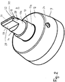
- the flow head 3 has a support member 9 with which it sits on the neck 2 of the container 1.
- the support member 9 is cylindrical and provided with an internal thread 10, with which the support member 9 is screwed onto the provided with an external thread 11 neck 2 of the container.
- the support member 9 is sufficiently dimensionally stable, so that the flow head 3 can be securely screwed onto the neck 2.
- the support member 9 may be exemplified with a snap-on profile, with which it can be snapped onto a corresponding counter-profile on the neck 2.
- the connecting portion between the support member 9 and the neck 2 is formed dense, so that no chemical from the container 1 can inadvertently escape to the outside.
- To the support member includes a bottom 12, which is disc-shaped and protrudes from the center of a head piece 13 on which the T-piece 4 sits.
- the head piece 13 has, as is apparent Fig. 2 results in a subsequent to the bottom 12 threaded lower portion 13a, which merges via a paragraph in a smaller diameter upper part 13b.
- the lower part 13a has greater wall thickness than the upper part 13b. Both parts 13a, 13b are cylindrical and each have a smaller diameter than the bottom 12th
- the T-piece 4 is screwed onto the lower, thicker in the wall thickness portion 13a threaded, whereby a secure attachment of the container 1 on the tee 4 is ensured.
- end face 14 of the upper part 13b projects from an end portion 15 which extends diametrically with respect to the upper part 13b of the head piece 13 and the front side is closed.
- a lug 16 From the underside of the bottom 12 of the flow head 3 is centrally from a lug 16 from which is provided at the free end with a diffuser disk 17. It is designed as over the circumference of the neck 16 circumferential flange.
- the approach has 16 circular cross-section.
- the diffuser disk 17 is a radial flange with a circular outline. The diameter of the diffuser disk 17 is smaller than the inner diameter of the neck 2 of the container 1.
- a hole i. First line 19 It extends axially through the bottom 12 and the head 13 to close to the end face of the end portion 15.
- the bore 19 opens against the inflow direction 20 of the water in the side wall of the end portion 15th
- a bore 24 which receives a metering element 25.
- the bore 24 extends into the bore 21 (FIG. Fig. 1 ).
- the metering element 25 is so long that it extends into the bore 21st can reach. With the metering element 25, the flow cross-section for the disinfectant through the bore 21 can be adjusted sensitively.
- FIG. 1 The lower end of the bore 21 is widened in diameter and receives a holding element 26, which is formed as a continuous sleeve and is held firmly in the extension 16 with its enlarged head. On the holding element 26 of the flexible suction hose 7 is pushed.
- the flow head 3 is advantageously made in one piece from plastic. With the support member 9, the flow head 3 can be easily mounted on the container 1 or easily remove it. In the installed position, the end portion 15 of the flow head 13 extends up to advantageously in the middle of the flow cross-section of the tee 4. Here, the end portion 15 is aligned so that it extends in the direction of flow 20 of the water. It can thereby flow past the end part 15 laterally. Since the end part 15 protrudes into the flow cross section for the water, a back pressure is generated in the region of this end part. It causes a portion of the water flows under pressure through the inlet opening 23 and the bore 19 into the container 1 and inside the container 1, an overpressure is generated.
- the two transverse to the flow direction 20 extending end faces of the end portion 15 are flat. They extend perpendicular to the direction of flow and thus offer a high resistance to the incoming water.
- the perpendicular to the end faces 27, 28 adjoining side surfaces 29, 30 which extend in the flow direction 20 are also flat.
- the head portion 31 of the end portion 15 tapers toward the free end of the end portion 15.
- the diffuser disk 17 extends over the circumference of the projection 16, the water is evenly distributed over the circumference and directed into the container interior.
- the diffuser disk 17 has such a diameter that only a narrow annular gap 32 remains between its edge and the inner wall of the neck 2 of the container 1, which contributes to the uniform and calmed supply of the pressurized water.
- the pressure relief valve 5 is provided. It ensures that the water pressure does not rise above a predetermined value, thereby impairing the disinfection or cleaning of the drinking water installation.
- the non-return valve 6 located in the flow direction behind the end portion 15 of the flow head 3 ensures that no drinking water from the drinking water installation is pushed back into the water supply.
- the chemical in container 1 is advantageously hydrogen peroxide H2O2. It ensures a reliable disinfection of the drinking water installation. It is prescribed that the chemicals are added to the drinking water in a certain concentration and must be rinsed out of the drinking water pipes after a certain exposure time. During the filling process, all sampling points one after the other at the drinking water installation until the disinfectant escapes at the respective extraction point. Then the sampling points are closed again, so that the disinfectant in the drinking water pipe can be effective. For example, the sampling points are closed for 24 hours before being opened again. Then all sampling points must be opened one after another until the disinfectant is no longer detectable.
- a dye is advantageously added to it when the disinfection process is started. Since hydrogen peroxide H2O2 is usually used as the disinfectant, that it is aggressive towards other components and destroys them during prolonged contact, the addition of the dye only shortly before the disinfection process ensures that the dye is not destroyed by the hydrogen peroxide H2O2.
- the installer can now easily determine at the respective sampling points, whether the disinfectant has been passed through the respective drinking water pipe. As soon as the colored liquid emerges from the sampling point, the installer is certain that the drinking water pipes located in front of the sampling point have come into contact with the disinfectant.
- the container 1 can be easily removed from the T-piece 4, the dye can be easily filled before the disinfection process in the container 1. Subsequently, the container is set again and the disinfection process started.
- the dye may be liquid, but also in solid form, for example in the form of tablets, powders, granules and the like.
- Suitable dyestuffs are dyestuffs which withstand the decomposition by hydrogen peroxide H202 as long as possible and color the mixture of water and chemical.
- any other suitable indicator can be used, for example an odorant or an indicator that can be easily detected by means of test strips or a measuring instrument at the sampling point. It is only important that the installer can safely determine at the sampling point that the disinfectant solution emerges from the respectively opened sampling point. Then it is ensured that the leading to the sampling point lines have come into contact with the disinfectant.
- the container 1 If the container 1 is emptied, it can be easily replaced with a full container 1. It is also possible to fill the container 1 again with the appropriate chemical.
- Suitable disinfectants besides hydrogen peroxide H2O2 are other known chemicals, such as, for example, sodium hypochlorite and chlorine dioxide. These include substances with a Chemical Abstracts Service (CAS) or European Inventory of Existing Commercial Chemical Substances (EINECS) number, which is specified in product standards and used for disinfection.
- CAS Chemical Abstracts Service
- EINECS European Inventory of Existing Commercial Chemical Substances
- the disinfectants may contain other substances in the case of manufacturer-specific preparations or formulations. The proportion of disinfectant depends on the application and the applicable regulations.
Landscapes
- Engineering & Computer Science (AREA)
- Chemical & Material Sciences (AREA)
- Chemical Kinetics & Catalysis (AREA)
- Mechanical Engineering (AREA)
- Physics & Mathematics (AREA)
- Fluid Mechanics (AREA)
- General Engineering & Computer Science (AREA)
- Life Sciences & Earth Sciences (AREA)
- Oil, Petroleum & Natural Gas (AREA)
- Wood Science & Technology (AREA)
- Organic Chemistry (AREA)
- Apparatus For Disinfection Or Sterilisation (AREA)
Claims (11)
- Dispositif de désinfection et de nettoyage de tuyaux, en particulier de conduites d'eau potable, pourvu d'au moins un contenant (1) et d'un raccord de tube (4), avec au moins un produit chimique, qui est logé dans l'au moins un contenant (1), qui par au moins une pièce de raccord (3) saillit dans la section transversale d'écoulement du raccord de tube (4) de telle sorte que lors de la circulation à travers le raccord de tube (4) d'un liquide dans la direction d'écoulement (20), il se forme à l'avant de la pièce de raccord (3) dans le raccord de tube (4) une pression de refoulement qui par l'intermédiaire d'au moins un premier conduit (19) de la pièce de raccord (3) exerce sur le produit chimique dans le contenant (1) une pression par laquelle le produit chimique est poussé dans au moins un deuxième conduit (21) de la pièce de raccord (3) et s'échappe dans la direction d'écoulement (20) derrière la pièce de raccord (3) dans le raccord de tube (4),
caractérisé en ce que la pièce de raccord (3) comporte une partie diffuseur (17) saillant dans le contenant (1), qui dispose d'une section transversale inférieure à celle du contenant (1) dans la zone de la partie diffuseur (17) et qui est prévue sur l'extrémité libre d'un embout (16) de la pièce de raccord (3) saillant dans le contenant (1),
en ce que le premier conduit (19) débouche avec un écart axial par rapport à la partie diffuseur (17) dans une surface d'enveloppe (18) de l'embout (16),
en ce que le deuxième conduit (21) débouche dans la face frontale de l'embout (16) et
en ce que sur le deuxième conduit (21) est raccordé un flexible aspirant (7). - Dispositif selon la revendication 1,
caractérisé en ce que la pièce de raccord (3) saillit par une partie extrême (15) dans le raccord de tube (4) dont la section transversale est inférieure à la section transversale d'écoulement du raccord de tube (4). - Dispositif selon la revendication 1 ou 2,
caractérisé en ce que la pièce de raccord (3) comporte une pièce de fixation (9) qui est susceptible d'être emboîtée sur un col (2) du contenant (1) et qui est avantageusement assemblé de manière amovible avec le col (2). - Dispositif selon la revendication 3,
caractérisé en ce que la pièce de fixation (9) peut se visser sur le col (2) du contenant (1). - Dispositif selon l'une quelconque des revendications 1 à 4,
caractérisé en ce que la partie diffuseur (17) a un contour de forme circulaire. - Dispositif selon l'une quelconque des revendications 1 à 5,
caractérisé en ce que dans la direction d'écoulement (20), à l'avant de la partie extrême (15) de la pièce de raccord (3), un clapet de surpression (5) peut se connecter sur le raccord de tube (4). - Dispositif selon l'une quelconque des revendications 1 à 6,
caractérisé en ce que dans la direction d'écoulement (20), à l'arrière de la partie extrême (15) de la pièce de raccord (3), un clapet anti-retour (6) peut se connecter sur le raccord de tube (4). - Dispositif selon l'une quelconque des revendications 1 à 7,
caractérisé en ce que la section transversale du deuxième conduit (21) est réglable par au moins un élément doseur (25), de préférence une vis doseuse. - Procédé de désinfection et de nettoyage de telles conduites, notamment des conduites d'eau potable en utilisant le dispositif selon l'une quelconque des revendications 1 à 8,
lors duquel, directement avant le début de la désinfection ou du nettoyage, on ajoute au produit chimique désinfectant ou nettoyant au moins un indicateur de présence du produit chimique permettant de constater la sortie du produit chimique hors du conduit. - Procédé selon la revendication 9,
caractérisé en ce que l'indicateur de présence est un colorant. - Procédé selon la revendication 10,
caractérisé en ce qu'on ajoute le colorant sous forme liquide ou solide.
Applications Claiming Priority (1)
| Application Number | Priority Date | Filing Date | Title |
|---|---|---|---|
| DE102014008181.8A DE102014008181A1 (de) | 2014-06-10 | 2014-06-10 | Einheit zur Desinfektion und /oder Reinigung von Leitungen, insbesondere von Trinkwasserleitungen, sowie Verfahren zur Desinfektion und /oder Reinigung solcher Leitungen |
Publications (3)
| Publication Number | Publication Date |
|---|---|
| EP2954960A2 EP2954960A2 (fr) | 2015-12-16 |
| EP2954960A3 EP2954960A3 (fr) | 2016-04-06 |
| EP2954960B1 true EP2954960B1 (fr) | 2019-08-07 |
Family
ID=53397757
Family Applications (1)
| Application Number | Title | Priority Date | Filing Date |
|---|---|---|---|
| EP15001686.3A Active EP2954960B1 (fr) | 2014-06-10 | 2015-06-08 | Dispositif de désinfection et de nettoyage de tuyaux, en particulier de conduites d'eau potable et procédé de désinfection et de nettoyage de telles conduites |
Country Status (3)
| Country | Link |
|---|---|
| EP (1) | EP2954960B1 (fr) |
| DE (1) | DE102014008181A1 (fr) |
| ES (1) | ES2751482T3 (fr) |
Families Citing this family (1)
| Publication number | Priority date | Publication date | Assignee | Title |
|---|---|---|---|---|
| EP4600223A1 (fr) * | 2024-02-12 | 2025-08-13 | Aspire Technology Group Ltd | Procédé de désinfection d'un système de fluide |
Family Cites Families (10)
| Publication number | Priority date | Publication date | Assignee | Title |
|---|---|---|---|---|
| US3726304A (en) * | 1971-11-08 | 1973-04-10 | C Cook | Fertilizer dispenser |
| JPS62250190A (ja) * | 1986-04-21 | 1987-10-31 | Taisho Kogyo Kk | 帯状走行体の洗滌装置 |
| US4691732A (en) * | 1986-08-01 | 1987-09-08 | Jandy Industries, Inc. | Pool chlorinator |
| FR2732333A1 (fr) * | 1995-04-03 | 1996-10-04 | Canevet Paul | Dispositif permettant de reutiliser des eaux usees issues du lavage des equipements de traite |
| US5730178A (en) * | 1996-07-05 | 1998-03-24 | Zhadanov; Eli | Device for introducing substances into water |
| JPH10151382A (ja) * | 1996-09-27 | 1998-06-09 | Aiwa Co Ltd | 水等の液体噴霧装置 |
| US5827434A (en) * | 1997-03-19 | 1998-10-27 | Yando; Daniel | Apparatus and methods for reducing and deterring biological contamination |
| US6609733B2 (en) * | 2001-01-29 | 2003-08-26 | E-Z Flo Injection Systems, Inc. | Differential pressure fitting |
| AT413032B (de) * | 2003-11-11 | 2005-10-15 | Thonhauser Gmbh Dipl Ing | Reinigungs-, desinfektions- und indikatormittel |
| DE102006060204A1 (de) * | 2006-12-18 | 2008-06-19 | Krones Ag | Verfahren zur Reinigung einer Anlage |
-
2014
- 2014-06-10 DE DE102014008181.8A patent/DE102014008181A1/de not_active Withdrawn
-
2015
- 2015-06-08 ES ES15001686T patent/ES2751482T3/es active Active
- 2015-06-08 EP EP15001686.3A patent/EP2954960B1/fr active Active
Non-Patent Citations (1)
| Title |
|---|
| None * |
Also Published As
| Publication number | Publication date |
|---|---|
| EP2954960A2 (fr) | 2015-12-16 |
| EP2954960A3 (fr) | 2016-04-06 |
| ES2751482T3 (es) | 2020-03-31 |
| DE102014008181A1 (de) | 2015-12-17 |
Similar Documents
| Publication | Publication Date | Title |
|---|---|---|
| WO2017032584A1 (fr) | Dispositif, système et procédé de rinçage automatique au moyen d'une soupape multiple | |
| EP2954960B1 (fr) | Dispositif de désinfection et de nettoyage de tuyaux, en particulier de conduites d'eau potable et procédé de désinfection et de nettoyage de telles conduites | |
| EP3107630A1 (fr) | Système de buse de fluide d'extinction pour système d'extinction d'incendie stationnaire pourvu d'une bague d'obturateur et buse de fluide d'extinction et bague d'obturateur destiné à celui-ci | |
| DE69312178T2 (de) | Elektronische Einheit für kontrollierte Abgaben von Desinfektionsflüssigkeiten und dergleichen in Sanitätsapparaten im Allgemeinen | |
| DE102009031043B4 (de) | Versorgungssystem für wenigstens einen Reinstwasserverbraucher, insbesondere Dialysegerät | |
| DE60119097T2 (de) | Dosiervorrichtung für einen flüssigen reagenten durch auflösung in einem flüssigen strom | |
| EP3222785A2 (fr) | Dispositif de rinçage destiné à recevoir une solution de rinçage provenant d'une conduite et procédé de rinçage d'une conduite | |
| EP1517213B1 (fr) | Appareil de dosage pour la production à partir de concentrés d'une solution de produit désinfectant prête à l'emploi | |
| DE19528160A1 (de) | Rohr- und Schlauchinstallation an und in Mediensäulen für die Behandlung von Körperflüssigkeiten, insbesondere für ein Dialysegerät | |
| WO2020254643A1 (fr) | Système de désinfection et/ou de nettoyage et procédé de désinfection et/ou nettoyage d'un système de douche | |
| EP3690152B1 (fr) | Sortie libre au-dessus d'un objet de drainage | |
| EP3464164B1 (fr) | Système de remplissage de cuves avec récipient intermédiaire | |
| EP3737441A1 (fr) | Dispositif d'évacuation d'eaux usées | |
| DE102017115226A1 (de) | Einspülvorrichtung für eine landwirtschaftliche Feldspritze | |
| DE102016110009A1 (de) | Vorrichtung zur Befüllung von Tanks mit Zwischenbehälter | |
| DE102017105418B4 (de) | Vorrichtung zur Befüllung von Tanks mit Zwischenbehälter | |
| EP2436654A2 (fr) | Dispositif pour une installation de préparation d'eau potable comprenant une tête de filtre | |
| DE10310874B4 (de) | Leckageerkennung bei einem Ventil | |
| EP4043648B1 (fr) | Dispositif de transfert de fluide destiné à transférer une solution de rinçage d'une conduite | |
| DE102017105417B4 (de) | Vorrichtung zur Befüllung von Tanks mit Zwischenbehälter | |
| DE202023101192U1 (de) | Armaturenanordnung zur Wasserbehandlung von Wasser für Heizkreisläufe | |
| DE102016200955B4 (de) | Blockiervorrichtung, Montagepaar aus Blockiervorrichtung und Montagewerkzeug zum Verhindern des unbeabsichtigten Austretens von Fluid aus einem Rohrsystem | |
| EP1860420A1 (fr) | Dispositif et méthode pour remplir et tester sous pression un système de tuyaux en utilisant de l'eau dégermée | |
| EP4049977A1 (fr) | Dispositif de sécurité destiné à la protection de l'eau potable contre la pollution par retours d'eau | |
| DE102017105419A1 (de) | Vorrichtung zur Befüllung von Tanks mit Zwischenbehälter |
Legal Events
| Date | Code | Title | Description |
|---|---|---|---|
| PUAI | Public reference made under article 153(3) epc to a published international application that has entered the european phase |
Free format text: ORIGINAL CODE: 0009012 |
|
| AK | Designated contracting states |
Kind code of ref document: A2 Designated state(s): AL AT BE BG CH CY CZ DE DK EE ES FI FR GB GR HR HU IE IS IT LI LT LU LV MC MK MT NL NO PL PT RO RS SE SI SK SM TR |
|
| AX | Request for extension of the european patent |
Extension state: BA ME |
|
| PUAL | Search report despatched |
Free format text: ORIGINAL CODE: 0009013 |
|
| AK | Designated contracting states |
Kind code of ref document: A3 Designated state(s): AL AT BE BG CH CY CZ DE DK EE ES FI FR GB GR HR HU IE IS IT LI LT LU LV MC MK MT NL NO PL PT RO RS SE SI SK SM TR |
|
| AX | Request for extension of the european patent |
Extension state: BA ME |
|
| RIC1 | Information provided on ipc code assigned before grant |
Ipc: B08B 9/032 20060101ALI20160226BHEP Ipc: C02F 1/68 20060101ALI20160226BHEP Ipc: B08B 9/027 20060101ALI20160226BHEP Ipc: B01F 5/04 20060101ALI20160226BHEP Ipc: C11D 3/48 20060101ALI20160226BHEP Ipc: C02F 1/72 20060101ALN20160226BHEP Ipc: F04F 1/06 20060101ALI20160226BHEP Ipc: B08B 9/08 20060101ALI20160226BHEP Ipc: B08B 3/08 20060101AFI20160226BHEP |
|
| 17P | Request for examination filed |
Effective date: 20161006 |
|
| RBV | Designated contracting states (corrected) |
Designated state(s): AL AT BE BG CH CY CZ DE DK EE ES FI FR GB GR HR HU IE IS IT LI LT LU LV MC MK MT NL NO PL PT RO RS SE SI SK SM TR |
|
| REG | Reference to a national code |
Ref country code: DE Ref legal event code: R079 Ref document number: 502015009847 Country of ref document: DE Free format text: PREVIOUS MAIN CLASS: B08B0003080000 Ipc: B08B0009027000 |
|
| RIC1 | Information provided on ipc code assigned before grant |
Ipc: B08B 9/032 20060101ALI20181219BHEP Ipc: C02F 1/72 20060101ALN20181219BHEP Ipc: C11D 3/48 20060101ALI20181219BHEP Ipc: B08B 9/027 20060101AFI20181219BHEP Ipc: B01F 3/08 20060101ALI20181219BHEP Ipc: C02F 1/68 20060101ALN20181219BHEP Ipc: F04F 5/10 20060101ALI20181219BHEP Ipc: B01F 5/04 20060101ALI20181219BHEP |
|
| GRAP | Despatch of communication of intention to grant a patent |
Free format text: ORIGINAL CODE: EPIDOSNIGR1 |
|
| STAA | Information on the status of an ep patent application or granted ep patent |
Free format text: STATUS: GRANT OF PATENT IS INTENDED |
|
| RIC1 | Information provided on ipc code assigned before grant |
Ipc: B01F 5/04 20060101ALI20190115BHEP Ipc: B01F 3/08 20060101ALI20190115BHEP Ipc: C11D 3/48 20060101ALI20190115BHEP Ipc: B08B 9/027 20060101AFI20190115BHEP Ipc: B08B 9/032 20060101ALI20190115BHEP Ipc: F04F 5/10 20060101ALI20190115BHEP Ipc: C02F 1/72 20060101ALN20190115BHEP Ipc: C02F 1/68 20060101ALN20190115BHEP |
|
| INTG | Intention to grant announced |
Effective date: 20190130 |
|
| GRAS | Grant fee paid |
Free format text: ORIGINAL CODE: EPIDOSNIGR3 |
|
| GRAA | (expected) grant |
Free format text: ORIGINAL CODE: 0009210 |
|
| STAA | Information on the status of an ep patent application or granted ep patent |
Free format text: STATUS: THE PATENT HAS BEEN GRANTED |
|
| AK | Designated contracting states |
Kind code of ref document: B1 Designated state(s): AL AT BE BG CH CY CZ DE DK EE ES FI FR GB GR HR HU IE IS IT LI LT LU LV MC MK MT NL NO PL PT RO RS SE SI SK SM TR |
|
| REG | Reference to a national code |
Ref country code: GB Ref legal event code: FG4D Free format text: NOT ENGLISH |
|
| REG | Reference to a national code |
Ref country code: CH Ref legal event code: EP Ref country code: AT Ref legal event code: REF Ref document number: 1163033 Country of ref document: AT Kind code of ref document: T Effective date: 20190815 |
|
| REG | Reference to a national code |
Ref country code: DE Ref legal event code: R096 Ref document number: 502015009847 Country of ref document: DE |
|
| REG | Reference to a national code |
Ref country code: IE Ref legal event code: FG4D Free format text: LANGUAGE OF EP DOCUMENT: GERMAN |
|
| REG | Reference to a national code |
Ref country code: NL Ref legal event code: MP Effective date: 20190807 |
|
| REG | Reference to a national code |
Ref country code: LT Ref legal event code: MG4D |
|
| PG25 | Lapsed in a contracting state [announced via postgrant information from national office to epo] |
Ref country code: NL Free format text: LAPSE BECAUSE OF FAILURE TO SUBMIT A TRANSLATION OF THE DESCRIPTION OR TO PAY THE FEE WITHIN THE PRESCRIBED TIME-LIMIT Effective date: 20190807 Ref country code: SE Free format text: LAPSE BECAUSE OF FAILURE TO SUBMIT A TRANSLATION OF THE DESCRIPTION OR TO PAY THE FEE WITHIN THE PRESCRIBED TIME-LIMIT Effective date: 20190807 Ref country code: BG Free format text: LAPSE BECAUSE OF FAILURE TO SUBMIT A TRANSLATION OF THE DESCRIPTION OR TO PAY THE FEE WITHIN THE PRESCRIBED TIME-LIMIT Effective date: 20191107 Ref country code: HR Free format text: LAPSE BECAUSE OF FAILURE TO SUBMIT A TRANSLATION OF THE DESCRIPTION OR TO PAY THE FEE WITHIN THE PRESCRIBED TIME-LIMIT Effective date: 20190807 Ref country code: PT Free format text: LAPSE BECAUSE OF FAILURE TO SUBMIT A TRANSLATION OF THE DESCRIPTION OR TO PAY THE FEE WITHIN THE PRESCRIBED TIME-LIMIT Effective date: 20191209 Ref country code: LT Free format text: LAPSE BECAUSE OF FAILURE TO SUBMIT A TRANSLATION OF THE DESCRIPTION OR TO PAY THE FEE WITHIN THE PRESCRIBED TIME-LIMIT Effective date: 20190807 Ref country code: FI Free format text: LAPSE BECAUSE OF FAILURE TO SUBMIT A TRANSLATION OF THE DESCRIPTION OR TO PAY THE FEE WITHIN THE PRESCRIBED TIME-LIMIT Effective date: 20190807 Ref country code: NO Free format text: LAPSE BECAUSE OF FAILURE TO SUBMIT A TRANSLATION OF THE DESCRIPTION OR TO PAY THE FEE WITHIN THE PRESCRIBED TIME-LIMIT Effective date: 20191107 |
|
| PG25 | Lapsed in a contracting state [announced via postgrant information from national office to epo] |
Ref country code: LV Free format text: LAPSE BECAUSE OF FAILURE TO SUBMIT A TRANSLATION OF THE DESCRIPTION OR TO PAY THE FEE WITHIN THE PRESCRIBED TIME-LIMIT Effective date: 20190807 Ref country code: IS Free format text: LAPSE BECAUSE OF FAILURE TO SUBMIT A TRANSLATION OF THE DESCRIPTION OR TO PAY THE FEE WITHIN THE PRESCRIBED TIME-LIMIT Effective date: 20191207 Ref country code: RS Free format text: LAPSE BECAUSE OF FAILURE TO SUBMIT A TRANSLATION OF THE DESCRIPTION OR TO PAY THE FEE WITHIN THE PRESCRIBED TIME-LIMIT Effective date: 20190807 Ref country code: AL Free format text: LAPSE BECAUSE OF FAILURE TO SUBMIT A TRANSLATION OF THE DESCRIPTION OR TO PAY THE FEE WITHIN THE PRESCRIBED TIME-LIMIT Effective date: 20190807 |
|
| PG25 | Lapsed in a contracting state [announced via postgrant information from national office to epo] |
Ref country code: TR Free format text: LAPSE BECAUSE OF FAILURE TO SUBMIT A TRANSLATION OF THE DESCRIPTION OR TO PAY THE FEE WITHIN THE PRESCRIBED TIME-LIMIT Effective date: 20190807 |
|
| REG | Reference to a national code |
Ref country code: ES Ref legal event code: FG2A Ref document number: 2751482 Country of ref document: ES Kind code of ref document: T3 Effective date: 20200331 |
|
| PG25 | Lapsed in a contracting state [announced via postgrant information from national office to epo] |
Ref country code: DK Free format text: LAPSE BECAUSE OF FAILURE TO SUBMIT A TRANSLATION OF THE DESCRIPTION OR TO PAY THE FEE WITHIN THE PRESCRIBED TIME-LIMIT Effective date: 20190807 Ref country code: EE Free format text: LAPSE BECAUSE OF FAILURE TO SUBMIT A TRANSLATION OF THE DESCRIPTION OR TO PAY THE FEE WITHIN THE PRESCRIBED TIME-LIMIT Effective date: 20190807 Ref country code: RO Free format text: LAPSE BECAUSE OF FAILURE TO SUBMIT A TRANSLATION OF THE DESCRIPTION OR TO PAY THE FEE WITHIN THE PRESCRIBED TIME-LIMIT Effective date: 20190807 Ref country code: PL Free format text: LAPSE BECAUSE OF FAILURE TO SUBMIT A TRANSLATION OF THE DESCRIPTION OR TO PAY THE FEE WITHIN THE PRESCRIBED TIME-LIMIT Effective date: 20190807 |
|
| PG25 | Lapsed in a contracting state [announced via postgrant information from national office to epo] |
Ref country code: SM Free format text: LAPSE BECAUSE OF FAILURE TO SUBMIT A TRANSLATION OF THE DESCRIPTION OR TO PAY THE FEE WITHIN THE PRESCRIBED TIME-LIMIT Effective date: 20190807 Ref country code: SK Free format text: LAPSE BECAUSE OF FAILURE TO SUBMIT A TRANSLATION OF THE DESCRIPTION OR TO PAY THE FEE WITHIN THE PRESCRIBED TIME-LIMIT Effective date: 20190807 Ref country code: CZ Free format text: LAPSE BECAUSE OF FAILURE TO SUBMIT A TRANSLATION OF THE DESCRIPTION OR TO PAY THE FEE WITHIN THE PRESCRIBED TIME-LIMIT Effective date: 20190807 Ref country code: IS Free format text: LAPSE BECAUSE OF FAILURE TO SUBMIT A TRANSLATION OF THE DESCRIPTION OR TO PAY THE FEE WITHIN THE PRESCRIBED TIME-LIMIT Effective date: 20200224 |
|
| REG | Reference to a national code |
Ref country code: DE Ref legal event code: R097 Ref document number: 502015009847 Country of ref document: DE |
|
| PLBE | No opposition filed within time limit |
Free format text: ORIGINAL CODE: 0009261 |
|
| STAA | Information on the status of an ep patent application or granted ep patent |
Free format text: STATUS: NO OPPOSITION FILED WITHIN TIME LIMIT |
|
| PG2D | Information on lapse in contracting state deleted |
Ref country code: IS |
|
| 26N | No opposition filed |
Effective date: 20200603 |
|
| PG25 | Lapsed in a contracting state [announced via postgrant information from national office to epo] |
Ref country code: SI Free format text: LAPSE BECAUSE OF FAILURE TO SUBMIT A TRANSLATION OF THE DESCRIPTION OR TO PAY THE FEE WITHIN THE PRESCRIBED TIME-LIMIT Effective date: 20190807 |
|
| PG25 | Lapsed in a contracting state [announced via postgrant information from national office to epo] |
Ref country code: MC Free format text: LAPSE BECAUSE OF FAILURE TO SUBMIT A TRANSLATION OF THE DESCRIPTION OR TO PAY THE FEE WITHIN THE PRESCRIBED TIME-LIMIT Effective date: 20190807 |
|
| REG | Reference to a national code |
Ref country code: CH Ref legal event code: PL |
|
| GBPC | Gb: european patent ceased through non-payment of renewal fee |
Effective date: 20200608 |
|
| PG25 | Lapsed in a contracting state [announced via postgrant information from national office to epo] |
Ref country code: LU Free format text: LAPSE BECAUSE OF NON-PAYMENT OF DUE FEES Effective date: 20200608 |
|
| REG | Reference to a national code |
Ref country code: BE Ref legal event code: MM Effective date: 20200630 |
|
| PG25 | Lapsed in a contracting state [announced via postgrant information from national office to epo] |
Ref country code: CH Free format text: LAPSE BECAUSE OF NON-PAYMENT OF DUE FEES Effective date: 20200630 Ref country code: IE Free format text: LAPSE BECAUSE OF NON-PAYMENT OF DUE FEES Effective date: 20200608 Ref country code: GB Free format text: LAPSE BECAUSE OF NON-PAYMENT OF DUE FEES Effective date: 20200608 Ref country code: LI Free format text: LAPSE BECAUSE OF NON-PAYMENT OF DUE FEES Effective date: 20200630 |
|
| PG25 | Lapsed in a contracting state [announced via postgrant information from national office to epo] |
Ref country code: BE Free format text: LAPSE BECAUSE OF NON-PAYMENT OF DUE FEES Effective date: 20200630 |
|
| REG | Reference to a national code |
Ref country code: AT Ref legal event code: MM01 Ref document number: 1163033 Country of ref document: AT Kind code of ref document: T Effective date: 20200608 |
|
| PG25 | Lapsed in a contracting state [announced via postgrant information from national office to epo] |
Ref country code: AT Free format text: LAPSE BECAUSE OF NON-PAYMENT OF DUE FEES Effective date: 20200608 |
|
| PG25 | Lapsed in a contracting state [announced via postgrant information from national office to epo] |
Ref country code: MT Free format text: LAPSE BECAUSE OF FAILURE TO SUBMIT A TRANSLATION OF THE DESCRIPTION OR TO PAY THE FEE WITHIN THE PRESCRIBED TIME-LIMIT Effective date: 20190807 Ref country code: CY Free format text: LAPSE BECAUSE OF FAILURE TO SUBMIT A TRANSLATION OF THE DESCRIPTION OR TO PAY THE FEE WITHIN THE PRESCRIBED TIME-LIMIT Effective date: 20190807 |
|
| PG25 | Lapsed in a contracting state [announced via postgrant information from national office to epo] |
Ref country code: MK Free format text: LAPSE BECAUSE OF FAILURE TO SUBMIT A TRANSLATION OF THE DESCRIPTION OR TO PAY THE FEE WITHIN THE PRESCRIBED TIME-LIMIT Effective date: 20190807 |
|
| PG25 | Lapsed in a contracting state [announced via postgrant information from national office to epo] |
Ref country code: GR Free format text: LAPSE BECAUSE OF FAILURE TO SUBMIT A TRANSLATION OF THE DESCRIPTION OR TO PAY THE FEE WITHIN THE PRESCRIBED TIME-LIMIT Effective date: 20190807 |
|
| P01 | Opt-out of the competence of the unified patent court (upc) registered |
Effective date: 20231115 |
|
| PGFP | Annual fee paid to national office [announced via postgrant information from national office to epo] |
Ref country code: IT Payment date: 20250530 Year of fee payment: 11 |
|
| PGFP | Annual fee paid to national office [announced via postgrant information from national office to epo] |
Ref country code: FR Payment date: 20250515 Year of fee payment: 11 |
|
| PGFP | Annual fee paid to national office [announced via postgrant information from national office to epo] |
Ref country code: ES Payment date: 20250702 Year of fee payment: 11 |
|
| PGFP | Annual fee paid to national office [announced via postgrant information from national office to epo] |
Ref country code: DE Payment date: 20250826 Year of fee payment: 11 |