EP2954986A1 - Dispositif et procédé de commande et de réglage d'un système multi-corps - Google Patents
Dispositif et procédé de commande et de réglage d'un système multi-corps Download PDFInfo
- Publication number
- EP2954986A1 EP2954986A1 EP14171752.0A EP14171752A EP2954986A1 EP 2954986 A1 EP2954986 A1 EP 2954986A1 EP 14171752 A EP14171752 A EP 14171752A EP 2954986 A1 EP2954986 A1 EP 2954986A1
- Authority
- EP
- European Patent Office
- Prior art keywords
- tcp
- movement
- force
- controlling
- regulating
- Prior art date
- Legal status (The legal status is an assumption and is not a legal conclusion. Google has not performed a legal analysis and makes no representation as to the accuracy of the status listed.)
- Granted
Links
Images



Classifications
-
- G—PHYSICS
- G05—CONTROLLING; REGULATING
- G05D—SYSTEMS FOR CONTROLLING OR REGULATING NON-ELECTRIC VARIABLES
- G05D17/00—Control of torque; Control of mechanical power
- G05D17/02—Control of torque; Control of mechanical power characterised by the use of electric means
-
- B—PERFORMING OPERATIONS; TRANSPORTING
- B25—HAND TOOLS; PORTABLE POWER-DRIVEN TOOLS; MANIPULATORS
- B25J—MANIPULATORS; CHAMBERS PROVIDED WITH MANIPULATION DEVICES
- B25J9/00—Program-controlled manipulators
- B25J9/16—Program controls
- B25J9/1628—Program controls characterised by the control loop
- B25J9/1638—Program controls characterised by the control loop compensation for arm bending/inertia, pay load weight/inertia
-
- G—PHYSICS
- G05—CONTROLLING; REGULATING
- G05B—CONTROL OR REGULATING SYSTEMS IN GENERAL; FUNCTIONAL ELEMENTS OF SUCH SYSTEMS; MONITORING OR TESTING ARRANGEMENTS FOR SUCH SYSTEMS OR ELEMENTS
- G05B13/00—Adaptive control systems, i.e. systems automatically adjusting themselves to have a performance which is optimum according to some preassigned criterion
- G05B13/02—Adaptive control systems, i.e. systems automatically adjusting themselves to have a performance which is optimum according to some preassigned criterion electric
- G05B13/04—Adaptive control systems, i.e. systems automatically adjusting themselves to have a performance which is optimum according to some preassigned criterion electric involving the use of models or simulators
-
- G—PHYSICS
- G05—CONTROLLING; REGULATING
- G05B—CONTROL OR REGULATING SYSTEMS IN GENERAL; FUNCTIONAL ELEMENTS OF SUCH SYSTEMS; MONITORING OR TESTING ARRANGEMENTS FOR SUCH SYSTEMS OR ELEMENTS
- G05B2219/00—Program-control systems
- G05B2219/30—Nc systems
- G05B2219/39—Robotics, robotics to robotics hand
- G05B2219/39176—Compensation deflection arm
-
- G—PHYSICS
- G05—CONTROLLING; REGULATING
- G05B—CONTROL OR REGULATING SYSTEMS IN GENERAL; FUNCTIONAL ELEMENTS OF SUCH SYSTEMS; MONITORING OR TESTING ARRANGEMENTS FOR SUCH SYSTEMS OR ELEMENTS
- G05B2219/00—Program-control systems
- G05B2219/30—Nc systems
- G05B2219/39—Robotics, robotics to robotics hand
- G05B2219/39194—Compensation gravity
-
- G—PHYSICS
- G05—CONTROLLING; REGULATING
- G05B—CONTROL OR REGULATING SYSTEMS IN GENERAL; FUNCTIONAL ELEMENTS OF SUCH SYSTEMS; MONITORING OR TESTING ARRANGEMENTS FOR SUCH SYSTEMS OR ELEMENTS
- G05B2219/00—Program-control systems
- G05B2219/30—Nc systems
- G05B2219/39—Robotics, robotics to robotics hand
- G05B2219/39319—Force control, force as reference, active compliance
Definitions
- the present invention relates to a device for controlling and regulating a movement of a system with a plurality of kinematically interacting individual bodies, of which at least one is a drive. Moreover, the present invention relates to a method for controlling and controlling a movement of such a system. Under such a system is understood, for example, a plant, a processing machine, a processing machine and in particular a robot or a machine tool.
- the drive is, for example, an electric motor or a hydraulic or pneumatic drive.
- Another approach to improve the absolute static accuracy is based on a reference position to measure the deviation at the TCP in a variety of points of the working space and add as a compensation value to the setpoint channel or to subtract from the actual value channel.
- the disadvantage of this method is the necessary effort and the cost of measuring the working space or the robot / machine. Measuring the deviations requires equipping the system with external measuring equipment. The grid of the measurement is determined on a case-by-case basis. The analysis must be repeated in each identical system.
- the tabulated correction values are also load-dependent, i. they apply exactly to a load case. Changes z. As the load, the values are no longer valid.
- the counterforce is based on a not infinitely rigid structure and can quite cause parasitic movements on the TCP.
- a robot arm has a plurality of links which are each movable with a motor (a link with associated drive or motor represents a motion axis, "axis" for short)
- the motion, in particular an acceleration, of one link can be applied to the link affect others, reducing the quasi-static accuracy being affected.
- the parasitic movement resulting from an acceleration of the leading axis has hitherto been compensated with a compensation value applied as a position setpoint.
- the torque is often controlled by a so-called torque precontrol.
- the parameterization of the torque precontrol requires the input of the axis moment of inertia in relation to the motor. On industrial robots, however, this information is not constant over the working space due to the structure.
- the total inertia seen by the engine is a function of the joint position. To calculate a torque setpoint so far, the engine acceleration is multiplied by a predetermined value of the axial inertia.
- the parameterization of the maximum axis acceleration takes place as a consequence of the design of the motor and the power section and is derived axis-wise from the maximum permissible current and the axis inertia. Since the maximum acceleration is to be entered as a constant value, only the point is relevant for its parameterization, where the axis inertia related to the motor reaches its maximum. It follows that in areas where this value is not reached, the power reserve is not utilized and a higher acceleration limit would theoretically be possible. Therefore, it may be desirable to calculate an acceleration reserve for each position or an adjustment of the acceleration limit for better utilization of the current limit. In path planning, position-dependent acceleration limits have not been considered so far.
- the object of the present invention is thus to propose a device for controlling and a corresponding method for controlling and regulating a movement of a system with a plurality of kinematically interacting individual bodies, in which the movement of the system as such can be carried out more accurately.
- the force-generating variable is the electric current, while the force-generating variable is the pressure in a hydraulic or pneumatic drive.
- the movement of the system is continuously controlled dynamically.
- force vectors and corresponding compensating variables are constantly recalculated so that a given trajectory can be better maintained.
- Precise trajectory compliance is required in many manufacturing tasks, but not in most pick-and-place tasks where known solutions are required EP 1 980 374 A2 suffice.
- the compensation quantity may be a compensation torque, a compensation force, a compensation speed or a compensation position.
- each of these sizes can be used individually or in combination to compensate.
- a control with the compensation torque as compensating variable leads to a more rapid compensation of the disturbing forces.
- a control with the compensation position as a compensation variable leads to a more precise compensation of the disturbing forces.
- the load calculating device preferably draws on a load model in which a location and / or direction and / or amplitude of a force introduction into one of the individual bodies is / are taken into account. In this way, the force introduction with all its parameters can be considered dynamically during a movement.
- control unit has a cascaded position control, speed control and current control (or regulation of the force-generating variable). This allows the movement of the system to be precisely controlled in all its details.
- the moment-calculating device for calculating the at least one balancing torque uses a multi-body model in which a mass and / or an elasticity and / or a damping and / or a linear dependence on degrees of freedom of each of the individual bodies is / are taken into account. In this way, all or the most important mechanical quantities can be taken into account when modeling the system.
- the multi-body model may be based on a linear differential equation system. This has the advantage that it can be solved without high computational effort.
- the differential equation system is based on a mass matrix, a damping matrix and a stiffness matrix in each case based on the individual bodies.
- the major mechanical parameters such as mass, damping and stiffness enter the multi-body model.
- inertial forces possibly also the Coriolis force
- centrifugal forces which respectively act on the individual bodies
- a maximum acceleration of one of the individual bodies or of a composite of a plurality of the individual bodies can be calculated continuously during the movement. This has the advantage that in each position, the acceleration limit can be adapted to better use of the current limit or pressure limit.
- the torque device and the control unit are designed so that they continuously reduce the excitation of at least one natural frequency of the system during the movement. This means that the natural frequencies are less excited, which leads to a better movement behavior of the system.
- the device for controlling and regulating may have a model of the controlled system of the system, wherein at least one ideal reference variable for the drive can be calculated with the model. This allows a definable dynamic for the axes to be specified.
- control and regulating device may comprise a model of the controlled system of the system, the model having an ideal torque of the drive for monitoring an actual torque of the drive is calculable.
- a model of the controlled system for example, drive torques of the real system can be monitored, as a result of which collisions can be deduced.
- a device may be used to control and regulate the movement of its multiple, kinematically interacting, single bodies.
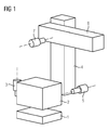
- FIG. 1 An example of such a multi-body system is in FIG. 1 played.
- This robot stands, for example, on a base plate 1.
- a robot body 2 can rotate on a vertical axis above the base plate 1. The rotation takes place by means of a motor 3.
- a motor 3 Although the following examples refer to an electric motor as a drive, in each case also a different drive can be used. In hydraulic and pneumatic drives then the pressure is the decisive factor instead of the current.
- the robot body 2 together with the motor 3 is a movement axis (in short: axis).
- a first arm 4 is rotatably supported by means of a motor 5.
- a second arm 6 is also rotatably supported by means of a further motor 7.
- the robot thus has three axes, of which the first axis with the individual bodies 2 (possibly including the motor 3), the second axis with the individual bodies 4 (possibly including motor 5) and the third axis with the individual bodies 6 (if necessary. including motor 7) is formed.
- each axis or each individual body has its own individual mass, damping, stiffness, etc. This means that, for example, the force of gravity or a process force has different effects on the system, depending on the position in which the axes are to each other. For example, if at the top of in FIG. 1 horizontally drawn second arm 6 pulls a force down, this has on the absolute position of the tip of the second arm 6 has a different effect than in the case that the second arm 6, for example, directed vertically upwards. Every force on the system has thus depending on the position of all axes effect.
- the behavior of the system can be described in a multi-body model representing a three-dimensional mechanical MIMO (multiple input, multiple output) model.
- M is the mass matrix
- D is the attenuation matrix
- K is the stiffness matrix
- T is the rectangular transformation matrix, which represents the relationship between the state quantities X and all degrees of freedom of the model.
- Each individual body of the system (see reference numerals 1, 2, 4 and 6 of FIG 1 ) is inherently rigid and has exactly six degrees of freedom (three translations and three rotations).
- the vector f is the vector of the external forces at the center of gravity of the respective individual body.
- this force vector includes gravity for each individual body and optionally a process force and the like (eg a force caused by pressing a tool against a workpiece).
- the state vector X describes the small movements around the original operating point.
- the matrices M, D, K and T are independent of the state variables.
- the joint position is not a state variable, but further parameters for the calculation of the matrices M, D, K and T.
- the model is preferably a linear multibody system that takes into account the positional dependence of the system behavior.
- An improved absolute accuracy can namely be achieved in that at any time engine forces to compensate for all disturbing forces are initiated. This results in an equilibrium state in which the small deviations at the TCP are zero.
- the description of the load case contains information about the location (s), the direction (s) and the amplitude (s) of the force application.
- As a force in addition to the aforementioned disturbing forces and machining forces are introduced, as they arise, for example, when milling or drilling.
- the matrix T TCP is an excerpt from the matrix T and describes the linear dependence between the coordinates of the TCP and the state variables.
- An important prerequisite for the solvability of the problem is that all zeros declared TCP coordinates are movable by the motors. However, this is the case for all machine and robot kinematics considered here. The robot must therefore be able to move the respective tool in the desired direction.
- the transmission of the engine torque to the mechanical structure requires the tensioning of the drive train spring by an angular offset on the engine.
- This angular offset is derived from the state vector X and must be taken into account in the setpoint generation.
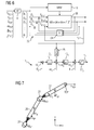
- FIG. 2 shows the structure of a method and a corresponding device for controlling and regulating the compensation of disturbance forces.
- Target coordinates for the TCP are specified by a higher-level unit, namely X TCP , Y TCP and Z TCP and ⁇ TCP , ⁇ TCP , ⁇ TCP .
- a coordinate transformation KF
- KF coordinate transformation
- a force vector f is determined for the respective joint coordinates as a function of a position, a direction and an amplitude of the force introduction. This is preferably done for each single body of the system.
- a multi-body model 10 processes the force vectors or the Force vector f further. On its basis and the basis of the joint coordinates, an engine torque or a corresponding current equivalent is calculated for the respective motor of each axle. In addition, in the multi-body model 10, angle offsets ⁇ are also calculated here. These calculations take into account the mass properties, the elasticity, the damping and linear dependencies of the degrees of freedom of the respective axes or individual bodies.
- the multi-body model 10 is based on the second-order linear differential equation system presented above.
- a control unit 11 connected downstream of the multi-body model 10 determines from the joint coordinates ⁇ 1 , ⁇ 2 , ⁇ 3 ,..., ⁇ i ,..., ⁇ n , the angular offsets ⁇ and the engine torques M a current i for driving an in FIG. 2 not shown engine one of the axes of the system, whereby the parasitic motion due to the disturbing forces is reduced or compensated.
- the control unit preferably has a cascaded position control, speed control and current control.
- a position controller 12 (preferably a P controller) is provided, which receives as an input quantity a sign-correct sum of the joint coordinates ⁇ 1 to ⁇ n , the angular offsets ⁇ and actual coordinates ⁇ j .
- the manipulated variable of the position controller 12 serves as an input variable for a downstream speed control, this input variable is summed an actual angular velocity ⁇ j in an adder 14 with the correct sign.
- the sum signal is fed to a speed controller 15 (preferably a PI controller).
- the output signal of the speed control or the speed controller 15 serves as input for a current control.
- This input variable is added in an adder a respective motor torque M and a corresponding equivalent and an actual current I j with the correct sign in an adder 16.
- This adder 16 as well as the other two adders 13 and 14 (in general: logic elements) optionally have a conversion or amplification functionality to obtain the respective desired size, for example by multiplication.
- the output signal of the adder 16 is fed to a current regulator 17, which outputs the manipulated variable for the motor, namely the current i.
- FIG. 2 For the sake of clarity, is in FIG. 2 a Störkraftkompensation only for a single axis shown. However, appropriate calculations and controls are preferably made for all axes of the system. In the simplest case, individual current values are calculated for each axis with which the respective motors are controlled.
- the multi-body model 10 can therefore be used to compensate for static disturbance forces from known load cases due to engine forces during the entire movement, ie always for the current coordinates and the current actual values.
- the multi-body model can be used to compensate for quasi-static load cases as well as acceleration operations.
- the acceleration of an axis and the counterforce generated in the joint may possibly lead to parasitic movements on the TCP due to the resilience of the structure.
- the second axle changes position or tilt due to its finite rigidity.
- Such and similar parasitic movements can be compensated for by means of compensatory movements of the remaining axes.
- the calculated compensation movement is pre-controlled as speed and torque.
- Such precontrol is for n axes A1, A2,..., Ai,..., An in FIG. 3 played.
- the regulatory structure is based on that of FIG. 2 , Identical elements are provided with the same reference numerals. In the following, only the differences are highlighted.
- control unit 11 receives as inputs the joint coordinate ⁇ 1 of the transformation unit 8 and the angular offset ⁇ 1 , a speed offset ⁇ 1 and a balancing moment M 1 of the multi-body model 10.
- control unit 11 i receives the joint coordinate ⁇ i from the transformation unit 8 and the angular offset ⁇ 2 , a speed offset ⁇ i and a compensation torque M i from the multi-body model 10.
- All n control units 11 1 to 11 n are structurally the same. Therefore, only the first control unit 11 1 will be described in detail here. It is based on the control unit 11 of FIG. 2 , whose description is referred again here. This results in accordance with the position controller 12 1 , the speed controller 15 1 and the current regulator 17 1 and the adder 13 1 , 14 1 and 16 first In the control unit 11 1, a first differentiator 18 1 is here additionally provided an additional guide value is determined taking into consideration the speed offset ⁇ 1 for the speed control with that of the angular displacement ⁇ 1, this reference variable is taken into account in the adder 14.
- this further speed control variable is converted into an acceleration variable and then multiplied in a multiplier 20 1 with a total axis inertia J Mot1 .
- the resulting value is finally made available to the adder 16 1 taking into account the compensation torque M 1 .
- the current signal i 1 results in driving the first axis.
- the current signals i i in the control unit 11 i are generated. In this way, parasitic movements that arise due to a quasi-static force can be compensated by appropriate compensatory movements.
- the axis inertia related to the respective engine can be calculated become.
- the axis inertia is determined from the modal mass associated with the rigid body mode (natural frequency 0 Hz).
- This rigid body fashion is purely theoretical in nature and refers to a movement without any vibration.
- only one motor must be allowed to move freely.
- the remaining axes are clamped.
- To calculate the modal mass it is sufficient to know only the eigenvector associated with the rigid body mode.
- the pseudo-inversion of the eigenvector is trivial and less stressful for the computational process than the inversion of a complete matrix.
- the determination of the eigenvector associated with the rigid body mode can be carried out in a simple manner, without consideration of the residual eigenvalues and vectors.
- the methodology is explained using the example of an arbitrary quadratic matrix A.
- X i ⁇ For the calculation of the modal masses the pseudo-inverse vector X i ⁇ is needed.
- the vector can be constructed element by element.
- X i ⁇ ⁇ 1 n 0 x i ⁇ 1 x i ⁇ 2 ⁇ x ij ⁇ x in ⁇ in which ⁇ j .
- ⁇ x ij 1 x j ⁇
- For x j ⁇ 0 x ij 0 otherwise
- n 0 is the number of elements of the vector X ⁇ nonzero.
- M and K correspond to the mass and stiffness matrices of the free engine system.
- Tj is the transformation matrix that satisfies the constraints, thus clamping all the motors or axes except the jth.
- the reduced vector X red contains only the state variables of those degrees of freedom that the structure has due to the joints, while the state vector X has all degrees of freedom. Since the rigid body mode no modal damping is assigned, the damping matrix can be taken out of the system of equations.
- FIG. 4 shows a schematic representation of the structure of the torque control.
- the coefficient J Mot is the total axle inertia related to the affected axle on the engine. It is in the control unit 11, structurally the control unit 11 1 of FIG. 3 taken into account in the multiplier 20, which forms the additional reference variable for the adder 16.
- the other elements of the control unit 11 correspond to those of the control unit 11 1 of FIG. 3 and are in FIG. 4 only shown without index "1".
- the overview is further in FIG. 4 dispensed with the representation of the load model 9, although it is naturally present. The same applies to the following Figures 5 and 6 ,
- the multi-body model can therefore be used to calculate the axis inertia J Mot for parameterization of the torque precontrol for each position. Therefore, the multi-body model has 10 in FIG. 4 a special output which provides a signal to the multiplier 20 to adjust the axis inertias J mot .
- the above multi-body model which is preferably based on the said linear differential equation system, can, as stated above, for the calculation of the respective Motors related axis inertia can be used for each position. From this, maximum axis accelerations can then be determined in an optionally extended model. The current maximum axis acceleration during the movement of the system definitely has an influence on the course of the movement.
- FIG. 5 which shows a structural overview of a pilot control with setpoint filter, is again limited to one axis for the sake of clarity. As well as in FIG. 4 was also dispensed with the representation of the load model 9. The rest in FIG. 5 Components represented by the same reference numerals as in the preceding figures have the same functionality as there. It is therefore referred to the respective description there.
- a setpoint filter 21 is provided here (SWF). This receives as input signal not only position information about the joint coordinates ⁇ 1 to ⁇ n directly, but also a speed signal formed therefrom by means of a differentiator 22 and acceleration signal formed therefrom by means of a dual differentiator 23. From these three signals, the setpoint filter 21 forms a filtered acceleration signal, which is supplied to the combining unit 20, which in turn with the filtered acceleration signal the total axial inertia J Mot provided by the multi-body model 10 and a corresponding result to the adder 16 for current control as a reference variable. In addition to this precontrol of the current for the current control, the speed control is pre-controlled with a filtered speed signal, which wins the setpoint filter 21 from the simply differentiated joint coordinates. For this purpose, the filtered speed signal is input to the adder 14.
- a filtered position signal which receives the setpoint filter 21 from the joint coordinates ⁇ 1 to ⁇ n .
- This filtered position signal is supplied to the adder 13 as a reference variable.
- the setpoint filter 21 special natural frequencies of the system can then position dependent, i. each time currently during acceleration, be filtered out.
- the natural frequencies of a robot change when it changes its arm position. In the extended state of the arm namely the natural oscillations are slower than in the tightened state of the arm.
- frequencies at 15 Hz are filtered out when the robot has extended the arm and filters out frequencies at 17 Hz when the arm is in an intermediate position, and filters out frequencies at 20 Hz when the arm is tightened.
- FIG. 6 Another possibility for adapting the reference variables is in the embodiment of FIG. 6 shown. Again, the system is like in FIG. 5 simplified.
- a model 38 of the route is implemented in the system here.
- the model 38 is based for example on the same linear differential equation system as the multi-body model 10.
- This model 38 of the track is embedded in a control loop 39 which is here for all three axes is located and has a regulator 24 in the feedback branch.
- the control circuit 39 results in an ideal controlled route whose controlled variable r 3 (in FIG. 6 only that drawn from the third axis of the n axes) is used as a reference variable for the control unit 11 3 . For this purpose, it is entered into the adder 13 3 for the position control.
- the result of the adder 13 3 is forwarded to the PI controller 12 3 , the result of which in turn is passed on to the adder 14 3 of the speed control.
- a differentiator 25 generates from the controlled variable r3 a speed signal which is also supplied to the adder 14 3 . After sign-correct summation the sum signal is fed to the PI controller 15 3 of the speed control, the output signal is forwarded to the adder 16 3 of the current control.
- the manipulated variable F Mot3 the ideal controlled system or the model 38 is additionally passed.
- the adders 13 3 , 14 3 and 16 3 are also supplied with the axis-specific actual values ⁇ j , ⁇ j and I j .
- the sum signal of the adder 16 3 is finally fed to the current regulator 17 3 , from which the resulting current signal i 3 for the third axis emerges.
- the same control units as the control unit 11 3 are provided for the remaining n-1 axes. For the sake of clarity, however, they are in FIG. 6 not shown.
- the multi-body model 10 in each case enters the currently valid matrices M, D and K to the model 38.
- the quantities recirculated in the ideal control 39 are linked together with the joint coordinates to the manipulated variables F Mot1 , F Mot2 , F Mot3 to F Motn , which respectively represent forces, of the controlled system.
- a model of the real distance can thus be used to perform an adaptation of the reference variables of the real control unit to reduce the excitation of the natural frequencies.
- FIG. 7 shows a concrete example of a 2D robot, with which the possibilities and advantages of the invention can be illustrated.
- the sketched 2D robot has here two arms 26 and 27, which can each be moved by a motor 28, 29.
- At the free end of the second arm 27 is the TCP.
- a force F TCP acts on it in a horizontal direction.
- a weight force F g1 is exerted on the first arm 26 and a weight force F g2 on the second arm.
- the TCP Tool Center Point
- the kinematic relationships for other designated points can be set up, eg. B. for the focal points of the body or the moving swivel.
- the motors and arms are not ideally rigidly connected but via an elastic spring that models the compliance of the drive trains.
- a stiffness matrix K can thus be specified which describes the restoring moments of the springs as a linear reaction to a deflection X.
- the driving moments of the motors, the weight forces of the body and optionally an additional force on the TCP act on the structure. This completes the descriptive system of equations. It describes the connections between movement and forces.
- the springs are stationary and the angular positions of the motor and arm are stationary equal. If forces (for example gravitation F g1 and F g2 or an external force F TCP ) act, the springs are deflected and the angular positions ⁇ M1 and ⁇ M2 of the motors 28 and 29 and the angular positions ⁇ 1 and ⁇ 2 of the arms 26 and 27 are not equal.
- forces for example gravitation F g1 and F g2 or an external force F TCP
- FIG. 8 shows results of simulation calculations, as the position of the robot of FIG. 7 according to a control method according to the prior art (control of the motor position, no compensation).
- the robot is upright in the y-direction according to line 30, when no gravity and no external force are acting on the TCP.
- FIG. 9 shows results of simulation calculations, as the position of the robot of FIG. 7 according to the method of the present invention.
- Line 35 shows the position of the 2D robot in gravity and different values for an external force on the TCP. The robot does not change its position due to the inventive dynamic control, even if the force F TCP changes.
- the system of motion and force equations developed above can be changed according to the forces (given movement) or after the displacement (given forces and moments).
- the number of independent variables is the same in each case (here four).
- the method according to the invention preferably evaluates the equation system Now, in such a way that a part of the motion coordinates (here position of the TCP) and a part of the acting forces is specified and resolved in a targeted manner according to the remaining free sizes (here torque and deflection of the motors).
- FIG. 9 illustrates FIG. 9 in that the structure does not move under the influence of external forces.
- the two motors compensate for the deflection by biasing the compliant drive trains to the required extent (fanned arrows 36 and 37). Both arms stay in the same position.
Landscapes
- Engineering & Computer Science (AREA)
- Physics & Mathematics (AREA)
- Automation & Control Theory (AREA)
- General Physics & Mathematics (AREA)
- Robotics (AREA)
- Mechanical Engineering (AREA)
- Health & Medical Sciences (AREA)
- Medical Informatics (AREA)
- Software Systems (AREA)
- Evolutionary Computation (AREA)
- Computer Vision & Pattern Recognition (AREA)
- Artificial Intelligence (AREA)
- Manipulator (AREA)
- Feedback Control In General (AREA)
- Numerical Control (AREA)
Priority Applications (3)
| Application Number | Priority Date | Filing Date | Title |
|---|---|---|---|
| EP14171752.0A EP2954986B1 (fr) | 2014-06-10 | 2014-06-10 | Dispositif et procédé de commande et de réglage d'un système multi-corps |
| JP2015114768A JP6430335B2 (ja) | 2014-06-10 | 2015-06-05 | 多数の要素システムを制御調節する装置および方法 |
| US14/734,747 US10007280B2 (en) | 2014-06-10 | 2015-06-09 | Apparatus and method for controlling and regulating a multi-element system |
Applications Claiming Priority (1)
| Application Number | Priority Date | Filing Date | Title |
|---|---|---|---|
| EP14171752.0A EP2954986B1 (fr) | 2014-06-10 | 2014-06-10 | Dispositif et procédé de commande et de réglage d'un système multi-corps |
Publications (2)
| Publication Number | Publication Date |
|---|---|
| EP2954986A1 true EP2954986A1 (fr) | 2015-12-16 |
| EP2954986B1 EP2954986B1 (fr) | 2020-05-06 |
Family
ID=50932995
Family Applications (1)
| Application Number | Title | Priority Date | Filing Date |
|---|---|---|---|
| EP14171752.0A Active EP2954986B1 (fr) | 2014-06-10 | 2014-06-10 | Dispositif et procédé de commande et de réglage d'un système multi-corps |
Country Status (3)
| Country | Link |
|---|---|
| US (1) | US10007280B2 (fr) |
| EP (1) | EP2954986B1 (fr) |
| JP (1) | JP6430335B2 (fr) |
Cited By (12)
| Publication number | Priority date | Publication date | Assignee | Title |
|---|---|---|---|---|
| CN106426164A (zh) * | 2016-09-27 | 2017-02-22 | 华南理工大学 | 一种冗余度双机械臂的多指标协调运动规划方法 |
| EP3287244A1 (fr) | 2016-08-26 | 2018-02-28 | Siemens Aktiengesellschaft | Compensation de couple de detente pour un robot industriel |
| DE102017104335A1 (de) * | 2017-03-02 | 2018-09-06 | Physik Instrumente (Pi) Gmbh & Co. Kg | Vorrichtung zur Bewegungsanalyse und Antriebsvorrichtung |
| DE102018004947B3 (de) | 2018-06-22 | 2019-07-18 | Sew-Eurodrive Gmbh & Co Kg | Verfahren zur Steuerung von Antrieben eines Roboters und Robotersystem |
| DE102018112360B3 (de) | 2018-05-23 | 2019-09-19 | Franka Emika Gmbh | Bereichsabhängige Kollisionsdetektion für einen Robotermanipulator |
| DE102018112370A1 (de) * | 2018-05-23 | 2019-11-28 | Franka Emika Gmbh | Richtungsabhängige Kollisionsdetektion für einen Robotermanipulator |
| DE102018128175A1 (de) * | 2018-11-12 | 2020-05-14 | Technische Universität Darmstadt | Verfahren und Vorrichtung zur Ermittlung von Verlagerungen eines Werkzeugmittelpunktes |
| EP3753682B1 (fr) | 2019-06-17 | 2021-12-29 | Schneider Electric Industries SAS | Procédé de commande d'un moteur d'entraînement |
| EP3961320A1 (fr) * | 2020-08-26 | 2022-03-02 | Siemens Aktiengesellschaft | Procédé et dispositif de guidage du mouvement d'un élément de machine mobile d'une machine |
| EP4119302A1 (fr) * | 2021-07-15 | 2023-01-18 | Siemens Aktiengesellschaft | Procédé pour estimer un ou plusieurs efforts de processus associés au point central d'outil d'une machine outil |
| EP4462202A1 (fr) | 2023-05-10 | 2024-11-13 | Siemens Aktiengesellschaft | Structure de régulateur pour entraînement direct/indirect mixte d'un élément de machine |
| EP4653149A1 (fr) | 2024-05-24 | 2025-11-26 | Siemens Aktiengesellschaft | Fonctionnement d'un système comprenant plusieurs éléments corporels |
Families Citing this family (18)
| Publication number | Priority date | Publication date | Assignee | Title |
|---|---|---|---|---|
| DE102013010290A1 (de) * | 2013-06-19 | 2014-12-24 | Kuka Laboratories Gmbh | Überwachen eines kinematisch redundanten Roboters |
| EP3115857A1 (fr) | 2015-07-09 | 2017-01-11 | Siemens Aktiengesellschaft | Procédé de détermination de trajectoire pour mouvements de temps mort |
| EP3131202A1 (fr) | 2015-08-11 | 2017-02-15 | Siemens Aktiengesellschaft | Procede d'inversion de filtre pour une commande de machine |
| EP3136192A1 (fr) | 2015-08-24 | 2017-03-01 | Siemens Aktiengesellschaft | Procede de commande de mouvement d'un outil et dispositif de commande |
| EP3144754A1 (fr) | 2015-09-17 | 2017-03-22 | Siemens Aktiengesellschaft | Amortissement des oscillations de charge sans moyen de mesure supplementaire cote charge |
| EP3176657A1 (fr) | 2015-12-02 | 2017-06-07 | Siemens Aktiengesellschaft | Determination de la rigidite d'une chaine cinematique d'une machine, en particulier d'une machine de production ou d'une machine-outil |
| JP6986373B2 (ja) * | 2017-06-21 | 2021-12-22 | 川崎重工業株式会社 | ロボットシステム及びロボットシステムの制御方法 |
| WO2019043852A1 (fr) * | 2017-08-30 | 2019-03-07 | 三菱電機株式会社 | Système de contrôle numérique et contrôleur de moteur |
| CN107398903B (zh) * | 2017-09-04 | 2020-06-30 | 杭州电子科技大学 | 工业机械手臂执行端的轨迹控制方法 |
| CN108015765B (zh) * | 2017-11-22 | 2019-06-18 | 华南理工大学 | 一种机器人运动规划的拓展解集对偶神经网络解决方法 |
| CN109597438B (zh) * | 2018-11-30 | 2021-09-24 | 上海航天控制技术研究所 | 一种控制力矩陀螺 |
| EP3685969A1 (fr) * | 2019-01-28 | 2020-07-29 | Siemens Aktiengesellschaft | Optimisation assistée par ordinateur d'un usinage à commande numérique d'une pièce à usiner |
| CN109856978B (zh) * | 2019-03-26 | 2022-02-15 | 广东电网有限责任公司 | 一种获取被控对象模型的方法及装置 |
| EP3764536A1 (fr) * | 2019-07-11 | 2021-01-13 | DENTSPLY SIRONA Inc. | Procédé de fonctionnement d'un moteur pas-à-pas dans une machine d'outil dentaire |
| EP3848951A1 (fr) * | 2020-01-07 | 2021-07-14 | ABB Power Grids Switzerland AG | Système de commande de fonctionnement d'un actionneur de moteur électrique pour disjoncteur moyenne à haute tension |
| JP2022177607A (ja) * | 2021-05-18 | 2022-12-01 | 株式会社豊田自動織機 | マニピュレータ |
| KR102683264B1 (ko) * | 2022-03-18 | 2024-07-08 | 영산대학교산학협력단 | 딥러닝을 활용한 재활치료용 로봇의 절대 위치 예측 방법 |
| CN119024762A (zh) * | 2024-08-31 | 2024-11-26 | 盐城市鑫纬嘉新能源科技有限公司 | 一种基于图像处理的黑色金属加工方法及系统 |
Citations (5)
| Publication number | Priority date | Publication date | Assignee | Title |
|---|---|---|---|---|
| EP1980374A2 (fr) | 2007-04-13 | 2008-10-15 | KUKA Roboter GmbH | Commande de robot, robot industriel et procédé d'obtention d'un modèle absolument précis |
| DE102007024143A1 (de) * | 2007-05-24 | 2008-11-27 | Dürr Systems GmbH | Bewegungssteuerung für elastische Roboterstrukturen |
| EP2492062A2 (fr) * | 2011-02-02 | 2012-08-29 | KUKA Roboter GmbH | Robot industriel |
| EP1403746B1 (fr) | 2002-09-30 | 2013-01-02 | Dürr Systems GmbH | Méthode de détection de collision |
| DE102011111758A1 (de) * | 2011-08-24 | 2013-02-28 | Dürr Systems GmbH | Steuerverfahren für einen Roboter |
Family Cites Families (22)
| Publication number | Priority date | Publication date | Assignee | Title |
|---|---|---|---|---|
| JPH05277976A (ja) * | 1992-03-31 | 1993-10-26 | Nippon Telegr & Teleph Corp <Ntt> | 動力学モデルパラメータ同定装置 |
| JP3681431B2 (ja) * | 1995-02-21 | 2005-08-10 | ファナック株式会社 | 直交座標系上で柔らかさが調節可能なサーボ系 |
| JP3968536B2 (ja) * | 1997-10-06 | 2007-08-29 | 株式会社安川電機 | 冗長自由度マニピュレータのコンプライアンス制御方法 |
| US6470225B1 (en) * | 1999-04-16 | 2002-10-22 | Siemens Energy & Automation, Inc. | Method and apparatus for automatically tuning feedforward parameters |
| SE0001312D0 (sv) * | 2000-04-10 | 2000-04-10 | Abb Ab | Industrirobot |
| US7390309B2 (en) * | 2002-09-23 | 2008-06-24 | Honda Motor Co., Ltd. | Human assist system using gravity compensation control system and method using multiple feasibility parameters |
| US7212886B2 (en) * | 2002-12-12 | 2007-05-01 | Kabushiki Kaisha Yaskawa Denki | Robot control apparatus and method |
| US8024068B2 (en) * | 2006-08-04 | 2011-09-20 | Hurco Companies, Inc. | Machine tool control system |
| JP5310557B2 (ja) | 2007-09-14 | 2013-10-09 | 株式会社安川電機 | ロボットの力制御方法、制御装置およびロボットシステム |
| JP2010012575A (ja) * | 2008-07-07 | 2010-01-21 | Sony Corp | 制御装置及び制御方法 |
| JP5459486B2 (ja) * | 2010-01-26 | 2014-04-02 | 株式会社Ihi | ロボットのキャリブレーション方法および装置 |
| JP5321532B2 (ja) * | 2010-04-28 | 2013-10-23 | 株式会社安川電機 | ロボットキャリブレーション装置及びキャリブレーション方法 |
| JP5311294B2 (ja) * | 2010-04-28 | 2013-10-09 | 株式会社安川電機 | ロボットの接触位置検出装置 |
| JP5447150B2 (ja) * | 2010-04-28 | 2014-03-19 | 株式会社安川電機 | ロボットの制御装置およびロボットを制御する方法 |
| US9652201B2 (en) * | 2010-10-01 | 2017-05-16 | Adobe Systems Incorporated | Methods and systems for physically-based runtime effects |
| US9002503B2 (en) * | 2011-04-04 | 2015-04-07 | Okuma Corporation | Method and program for calculating correction value for machine tool |
| EP2574820B1 (fr) * | 2011-09-30 | 2014-04-16 | Siemens Aktiengesellschaft | Machine de traitement dotée de structures mécaniques mobiles à compensation d'oscillations |
| JP5962020B2 (ja) * | 2012-01-17 | 2016-08-03 | セイコーエプソン株式会社 | ロボット制御装置、ロボットシステム、ロボット及びロボット制御方法 |
| JP5870801B2 (ja) * | 2012-03-26 | 2016-03-01 | 株式会社デンソーウェーブ | ロボットの制御方法、およびロボットの制御装置 |
| US8803465B1 (en) * | 2012-04-06 | 2014-08-12 | Exelis Inc. | Frequency-selective command profile motion control |
| JP5409844B2 (ja) * | 2012-05-30 | 2014-02-05 | 株式会社神戸製鋼所 | 多関節ロボットの軌跡制御装置および制御方法 |
| DE102013010290A1 (de) * | 2013-06-19 | 2014-12-24 | Kuka Laboratories Gmbh | Überwachen eines kinematisch redundanten Roboters |
-
2014
- 2014-06-10 EP EP14171752.0A patent/EP2954986B1/fr active Active
-
2015
- 2015-06-05 JP JP2015114768A patent/JP6430335B2/ja active Active
- 2015-06-09 US US14/734,747 patent/US10007280B2/en active Active
Patent Citations (5)
| Publication number | Priority date | Publication date | Assignee | Title |
|---|---|---|---|---|
| EP1403746B1 (fr) | 2002-09-30 | 2013-01-02 | Dürr Systems GmbH | Méthode de détection de collision |
| EP1980374A2 (fr) | 2007-04-13 | 2008-10-15 | KUKA Roboter GmbH | Commande de robot, robot industriel et procédé d'obtention d'un modèle absolument précis |
| DE102007024143A1 (de) * | 2007-05-24 | 2008-11-27 | Dürr Systems GmbH | Bewegungssteuerung für elastische Roboterstrukturen |
| EP2492062A2 (fr) * | 2011-02-02 | 2012-08-29 | KUKA Roboter GmbH | Robot industriel |
| DE102011111758A1 (de) * | 2011-08-24 | 2013-02-28 | Dürr Systems GmbH | Steuerverfahren für einen Roboter |
Cited By (24)
| Publication number | Priority date | Publication date | Assignee | Title |
|---|---|---|---|---|
| EP3287244A1 (fr) | 2016-08-26 | 2018-02-28 | Siemens Aktiengesellschaft | Compensation de couple de detente pour un robot industriel |
| WO2018037011A1 (fr) | 2016-08-26 | 2018-03-01 | Siemens Aktiengesellschaft | Compensation de couple de saillance dans un robot industriel |
| CN106426164A (zh) * | 2016-09-27 | 2017-02-22 | 华南理工大学 | 一种冗余度双机械臂的多指标协调运动规划方法 |
| CN106426164B (zh) * | 2016-09-27 | 2019-04-09 | 华南理工大学 | 一种冗余度双机械臂的多指标协调运动规划方法 |
| DE102017104335A1 (de) * | 2017-03-02 | 2018-09-06 | Physik Instrumente (Pi) Gmbh & Co. Kg | Vorrichtung zur Bewegungsanalyse und Antriebsvorrichtung |
| WO2018158120A1 (fr) | 2017-03-02 | 2018-09-07 | Physik Instrumente (Pi) Gmbh & Co. Kg | Dispositif d'analyse de déplacement et dispositif d'entrainement |
| DE102018112370B4 (de) | 2018-05-23 | 2021-09-16 | Franka Emika Gmbh | Richtungsabhängige Kollisionsdetektion für einen Robotermanipulator |
| DE102018112360B3 (de) | 2018-05-23 | 2019-09-19 | Franka Emika Gmbh | Bereichsabhängige Kollisionsdetektion für einen Robotermanipulator |
| DE102018112370A1 (de) * | 2018-05-23 | 2019-11-28 | Franka Emika Gmbh | Richtungsabhängige Kollisionsdetektion für einen Robotermanipulator |
| US20210268656A1 (en) * | 2018-06-22 | 2021-09-02 | Sew-Eurodrive Gmbh & Co. Kg | Method for controlling drives of a robot, and robot system |
| US11904479B2 (en) * | 2018-06-22 | 2024-02-20 | Sew-Eurodrive Gmbh & Co. Kg | Method for controlling drives of a robot, and robot system |
| DE102019003971A1 (de) | 2018-06-22 | 2019-12-24 | Sew-Eurodrive Gmbh & Co Kg | Verfahren zur Steuerung von Antrieben eines Roboters und Robotersystem |
| DE102018004947B3 (de) | 2018-06-22 | 2019-07-18 | Sew-Eurodrive Gmbh & Co Kg | Verfahren zur Steuerung von Antrieben eines Roboters und Robotersystem |
| WO2019242885A1 (fr) | 2018-06-22 | 2019-12-26 | Sew-Eurodrive Gmbh & Co. Kg | Procédé de commande de mécanismes d'entraînement d'un robot et système de robot |
| DE102018128175A1 (de) * | 2018-11-12 | 2020-05-14 | Technische Universität Darmstadt | Verfahren und Vorrichtung zur Ermittlung von Verlagerungen eines Werkzeugmittelpunktes |
| US11942883B2 (en) | 2019-06-17 | 2024-03-26 | Schneider Electric Industries Sas | Method of controlling a drive motor |
| EP3753682B1 (fr) | 2019-06-17 | 2021-12-29 | Schneider Electric Industries SAS | Procédé de commande d'un moteur d'entraînement |
| EP3961320A1 (fr) * | 2020-08-26 | 2022-03-02 | Siemens Aktiengesellschaft | Procédé et dispositif de guidage du mouvement d'un élément de machine mobile d'une machine |
| US12122051B2 (en) | 2020-08-26 | 2024-10-22 | Siemens Aktiengesellschaft | Method and device for guiding the movement of a movable machine element of a machine |
| EP4119302A1 (fr) * | 2021-07-15 | 2023-01-18 | Siemens Aktiengesellschaft | Procédé pour estimer un ou plusieurs efforts de processus associés au point central d'outil d'une machine outil |
| WO2023285023A1 (fr) * | 2021-07-15 | 2023-01-19 | Siemens Aktiengesellschaft | Procédé d'estimation d'une ou de plusieurs forces de traitement associées à un point central d'outil d'une machine-outil |
| EP4462202A1 (fr) | 2023-05-10 | 2024-11-13 | Siemens Aktiengesellschaft | Structure de régulateur pour entraînement direct/indirect mixte d'un élément de machine |
| EP4653149A1 (fr) | 2024-05-24 | 2025-11-26 | Siemens Aktiengesellschaft | Fonctionnement d'un système comprenant plusieurs éléments corporels |
| WO2025242676A1 (fr) | 2024-05-24 | 2025-11-27 | Siemens Aktiengesellschaft | Fonctionnement d'un système comportant une pluralité d'éléments de corps |
Also Published As
| Publication number | Publication date |
|---|---|
| EP2954986B1 (fr) | 2020-05-06 |
| US20150355647A1 (en) | 2015-12-10 |
| JP2015231663A (ja) | 2015-12-24 |
| JP6430335B2 (ja) | 2018-11-28 |
| US10007280B2 (en) | 2018-06-26 |
Similar Documents
| Publication | Publication Date | Title |
|---|---|---|
| EP2954986B1 (fr) | Dispositif et procédé de commande et de réglage d'un système multi-corps | |
| DE102016012065B4 (de) | Robotersystem mit Funktion zum Berechnen von Position und Ausrichtung eines Sensors | |
| EP3402632B1 (fr) | Détermination d'une orientation d'un robot par rapport à la direction de la gravité | |
| DE102012104194B4 (de) | Roboter und Punktschweissroboter mit lernender Steuerungsfunktion | |
| DE2656433C3 (de) | Verfahren und Anordnung zur Regelung von Manipulatoen und industriellen Robotern | |
| DE602005001651T2 (de) | Gerät zur Dämpfung von Vibrationen | |
| DE102015004483B4 (de) | Robotersteuerung und Robotersystem zum Bewegen eines Roboters als Reaktion auf eine Kraft | |
| DE102015004481B4 (de) | Robotersteuervorrichtung zum Steuern eines gemäß einer ausgeübten Kraft bewegten Roboters | |
| DE102014226936B3 (de) | Ganzkörperimpedanz für mobile Roboter | |
| DE102015011113B4 (de) | Motorsteuersystem, das eine Interferenz zwischen Achsen kompensiert | |
| DE102012101979B4 (de) | Verfahren und Vorrichtung zur Erzeugung einer Relativbewegung | |
| DE102009014766A1 (de) | Überlagerte Achsen bei einer Vorrichtung zur Bearbeitung eines Werkstücks mit einem Werkzeug | |
| EP1920892B1 (fr) | Commande de robot, robot et procédé de commande d'un robot | |
| EP1934660B1 (fr) | Procede et dispositif pour guider le deplacement d'un element mobile d'une machine | |
| WO2004102292A2 (fr) | Procede pour guider le mouvement d'un element mobile d'une machine outil ou machine de production a commande numerique | |
| DE102018102995A1 (de) | Redundanter unterbetätigter roboter mit multimodus-steuerungsrahmen | |
| EP1980374A2 (fr) | Commande de robot, robot industriel et procédé d'obtention d'un modèle absolument précis | |
| WO2023279132A1 (fr) | Procédé et dispositif pour déterminer une trajectoire optimale en termes de temps | |
| DE102020127532B3 (de) | Regelungsverfahren zum Regeln des Drehmoments und/oder der Position mindestens eines elastizitätsbehafteten Gelenks einer Handhabungsvorrichtung, Drehmomentregler, Positionsregler und Verwendung des Verfahrens zur Regelung der Position und/oder des Drehmoments mindestens eines elastizitätsbehafteten Gelenks einer Handhabungsvorrichtung | |
| EP4061586B1 (fr) | Mesure de force et génération de force dans des manipulateurs robotiques redondants | |
| WO1998015880A1 (fr) | Procede et structure de regulation pour l'asservissement de couples de systemes multimasses, a commande numerique, elastiques et pouvant donc osciller | |
| DE102008050863B4 (de) | Positionssteuerungsvorrichtung | |
| EP4084937B1 (fr) | Déplacement d'une référence fixée à un robot | |
| DE102022126205B4 (de) | Robotersystem zum Bewegen einer Nutzlast mit minimalem Schwanken der Nutzlast und erhöhter Positionierungsgenauigkeit | |
| DE102008062978B4 (de) | Handhabungsmaschine und Verfahren zu ihrem Betrieb |
Legal Events
| Date | Code | Title | Description |
|---|---|---|---|
| PUAI | Public reference made under article 153(3) epc to a published international application that has entered the european phase |
Free format text: ORIGINAL CODE: 0009012 |
|
| 17P | Request for examination filed |
Effective date: 20150505 |
|
| AK | Designated contracting states |
Kind code of ref document: A1 Designated state(s): AL AT BE BG CH CY CZ DE DK EE ES FI FR GB GR HR HU IE IS IT LI LT LU LV MC MK MT NL NO PL PT RO RS SE SI SK SM TR |
|
| AX | Request for extension of the european patent |
Extension state: BA ME |
|
| RAP1 | Party data changed (applicant data changed or rights of an application transferred) |
Owner name: SIEMENS AKTIENGESELLSCHAFT |
|
| STAA | Information on the status of an ep patent application or granted ep patent |
Free format text: STATUS: EXAMINATION IS IN PROGRESS |
|
| 17Q | First examination report despatched |
Effective date: 20190513 |
|
| GRAP | Despatch of communication of intention to grant a patent |
Free format text: ORIGINAL CODE: EPIDOSNIGR1 |
|
| STAA | Information on the status of an ep patent application or granted ep patent |
Free format text: STATUS: GRANT OF PATENT IS INTENDED |
|
| INTG | Intention to grant announced |
Effective date: 20191220 |
|
| GRAS | Grant fee paid |
Free format text: ORIGINAL CODE: EPIDOSNIGR3 |
|
| GRAA | (expected) grant |
Free format text: ORIGINAL CODE: 0009210 |
|
| STAA | Information on the status of an ep patent application or granted ep patent |
Free format text: STATUS: THE PATENT HAS BEEN GRANTED |
|
| AK | Designated contracting states |
Kind code of ref document: B1 Designated state(s): AL AT BE BG CH CY CZ DE DK EE ES FI FR GB GR HR HU IE IS IT LI LT LU LV MC MK MT NL NO PL PT RO RS SE SI SK SM TR |
|
| REG | Reference to a national code |
Ref country code: GB Ref legal event code: FG4D Free format text: NOT ENGLISH |
|
| REG | Reference to a national code |
Ref country code: CH Ref legal event code: EP Ref country code: AT Ref legal event code: REF Ref document number: 1266034 Country of ref document: AT Kind code of ref document: T Effective date: 20200515 |
|
| REG | Reference to a national code |
Ref country code: DE Ref legal event code: R096 Ref document number: 502014014116 Country of ref document: DE |
|
| REG | Reference to a national code |
Ref country code: IE Ref legal event code: FG4D Free format text: LANGUAGE OF EP DOCUMENT: GERMAN |
|
| REG | Reference to a national code |
Ref country code: LT Ref legal event code: MG4D |
|
| REG | Reference to a national code |
Ref country code: NL Ref legal event code: MP Effective date: 20200506 |
|
| PG25 | Lapsed in a contracting state [announced via postgrant information from national office to epo] |
Ref country code: SE Free format text: LAPSE BECAUSE OF FAILURE TO SUBMIT A TRANSLATION OF THE DESCRIPTION OR TO PAY THE FEE WITHIN THE PRESCRIBED TIME-LIMIT Effective date: 20200506 Ref country code: PT Free format text: LAPSE BECAUSE OF FAILURE TO SUBMIT A TRANSLATION OF THE DESCRIPTION OR TO PAY THE FEE WITHIN THE PRESCRIBED TIME-LIMIT Effective date: 20200907 Ref country code: FI Free format text: LAPSE BECAUSE OF FAILURE TO SUBMIT A TRANSLATION OF THE DESCRIPTION OR TO PAY THE FEE WITHIN THE PRESCRIBED TIME-LIMIT Effective date: 20200506 Ref country code: GR Free format text: LAPSE BECAUSE OF FAILURE TO SUBMIT A TRANSLATION OF THE DESCRIPTION OR TO PAY THE FEE WITHIN THE PRESCRIBED TIME-LIMIT Effective date: 20200807 Ref country code: NO Free format text: LAPSE BECAUSE OF FAILURE TO SUBMIT A TRANSLATION OF THE DESCRIPTION OR TO PAY THE FEE WITHIN THE PRESCRIBED TIME-LIMIT Effective date: 20200806 Ref country code: IS Free format text: LAPSE BECAUSE OF FAILURE TO SUBMIT A TRANSLATION OF THE DESCRIPTION OR TO PAY THE FEE WITHIN THE PRESCRIBED TIME-LIMIT Effective date: 20200906 Ref country code: LT Free format text: LAPSE BECAUSE OF FAILURE TO SUBMIT A TRANSLATION OF THE DESCRIPTION OR TO PAY THE FEE WITHIN THE PRESCRIBED TIME-LIMIT Effective date: 20200506 |
|
| PG25 | Lapsed in a contracting state [announced via postgrant information from national office to epo] |
Ref country code: LV Free format text: LAPSE BECAUSE OF FAILURE TO SUBMIT A TRANSLATION OF THE DESCRIPTION OR TO PAY THE FEE WITHIN THE PRESCRIBED TIME-LIMIT Effective date: 20200506 Ref country code: RS Free format text: LAPSE BECAUSE OF FAILURE TO SUBMIT A TRANSLATION OF THE DESCRIPTION OR TO PAY THE FEE WITHIN THE PRESCRIBED TIME-LIMIT Effective date: 20200506 Ref country code: BG Free format text: LAPSE BECAUSE OF FAILURE TO SUBMIT A TRANSLATION OF THE DESCRIPTION OR TO PAY THE FEE WITHIN THE PRESCRIBED TIME-LIMIT Effective date: 20200806 Ref country code: HR Free format text: LAPSE BECAUSE OF FAILURE TO SUBMIT A TRANSLATION OF THE DESCRIPTION OR TO PAY THE FEE WITHIN THE PRESCRIBED TIME-LIMIT Effective date: 20200506 |
|
| PG25 | Lapsed in a contracting state [announced via postgrant information from national office to epo] |
Ref country code: NL Free format text: LAPSE BECAUSE OF FAILURE TO SUBMIT A TRANSLATION OF THE DESCRIPTION OR TO PAY THE FEE WITHIN THE PRESCRIBED TIME-LIMIT Effective date: 20200506 Ref country code: AL Free format text: LAPSE BECAUSE OF FAILURE TO SUBMIT A TRANSLATION OF THE DESCRIPTION OR TO PAY THE FEE WITHIN THE PRESCRIBED TIME-LIMIT Effective date: 20200506 |
|
| PG25 | Lapsed in a contracting state [announced via postgrant information from national office to epo] |
Ref country code: CZ Free format text: LAPSE BECAUSE OF FAILURE TO SUBMIT A TRANSLATION OF THE DESCRIPTION OR TO PAY THE FEE WITHIN THE PRESCRIBED TIME-LIMIT Effective date: 20200506 Ref country code: RO Free format text: LAPSE BECAUSE OF FAILURE TO SUBMIT A TRANSLATION OF THE DESCRIPTION OR TO PAY THE FEE WITHIN THE PRESCRIBED TIME-LIMIT Effective date: 20200506 Ref country code: EE Free format text: LAPSE BECAUSE OF FAILURE TO SUBMIT A TRANSLATION OF THE DESCRIPTION OR TO PAY THE FEE WITHIN THE PRESCRIBED TIME-LIMIT Effective date: 20200506 Ref country code: DK Free format text: LAPSE BECAUSE OF FAILURE TO SUBMIT A TRANSLATION OF THE DESCRIPTION OR TO PAY THE FEE WITHIN THE PRESCRIBED TIME-LIMIT Effective date: 20200506 Ref country code: SM Free format text: LAPSE BECAUSE OF FAILURE TO SUBMIT A TRANSLATION OF THE DESCRIPTION OR TO PAY THE FEE WITHIN THE PRESCRIBED TIME-LIMIT Effective date: 20200506 Ref country code: ES Free format text: LAPSE BECAUSE OF FAILURE TO SUBMIT A TRANSLATION OF THE DESCRIPTION OR TO PAY THE FEE WITHIN THE PRESCRIBED TIME-LIMIT Effective date: 20200506 |
|
| REG | Reference to a national code |
Ref country code: CH Ref legal event code: PL |
|
| REG | Reference to a national code |
Ref country code: DE Ref legal event code: R097 Ref document number: 502014014116 Country of ref document: DE |
|
| PG25 | Lapsed in a contracting state [announced via postgrant information from national office to epo] |
Ref country code: PL Free format text: LAPSE BECAUSE OF FAILURE TO SUBMIT A TRANSLATION OF THE DESCRIPTION OR TO PAY THE FEE WITHIN THE PRESCRIBED TIME-LIMIT Effective date: 20200506 Ref country code: SK Free format text: LAPSE BECAUSE OF FAILURE TO SUBMIT A TRANSLATION OF THE DESCRIPTION OR TO PAY THE FEE WITHIN THE PRESCRIBED TIME-LIMIT Effective date: 20200506 Ref country code: MC Free format text: LAPSE BECAUSE OF FAILURE TO SUBMIT A TRANSLATION OF THE DESCRIPTION OR TO PAY THE FEE WITHIN THE PRESCRIBED TIME-LIMIT Effective date: 20200506 |
|
| PLBE | No opposition filed within time limit |
Free format text: ORIGINAL CODE: 0009261 |
|
| STAA | Information on the status of an ep patent application or granted ep patent |
Free format text: STATUS: NO OPPOSITION FILED WITHIN TIME LIMIT |
|
| PG25 | Lapsed in a contracting state [announced via postgrant information from national office to epo] |
Ref country code: LU Free format text: LAPSE BECAUSE OF NON-PAYMENT OF DUE FEES Effective date: 20200610 |
|
| 26N | No opposition filed |
Effective date: 20210209 |
|
| REG | Reference to a national code |
Ref country code: BE Ref legal event code: MM Effective date: 20200630 |
|
| GBPC | Gb: european patent ceased through non-payment of renewal fee |
Effective date: 20200806 |
|
| PG25 | Lapsed in a contracting state [announced via postgrant information from national office to epo] |
Ref country code: CH Free format text: LAPSE BECAUSE OF NON-PAYMENT OF DUE FEES Effective date: 20200630 Ref country code: LI Free format text: LAPSE BECAUSE OF NON-PAYMENT OF DUE FEES Effective date: 20200630 Ref country code: IE Free format text: LAPSE BECAUSE OF NON-PAYMENT OF DUE FEES Effective date: 20200610 |
|
| PG25 | Lapsed in a contracting state [announced via postgrant information from national office to epo] |
Ref country code: SI Free format text: LAPSE BECAUSE OF FAILURE TO SUBMIT A TRANSLATION OF THE DESCRIPTION OR TO PAY THE FEE WITHIN THE PRESCRIBED TIME-LIMIT Effective date: 20200506 Ref country code: BE Free format text: LAPSE BECAUSE OF NON-PAYMENT OF DUE FEES Effective date: 20200630 |
|
| REG | Reference to a national code |
Ref country code: AT Ref legal event code: MM01 Ref document number: 1266034 Country of ref document: AT Kind code of ref document: T Effective date: 20200610 |
|
| PG25 | Lapsed in a contracting state [announced via postgrant information from national office to epo] |
Ref country code: GB Free format text: LAPSE BECAUSE OF NON-PAYMENT OF DUE FEES Effective date: 20200806 |
|
| PG25 | Lapsed in a contracting state [announced via postgrant information from national office to epo] |
Ref country code: AT Free format text: LAPSE BECAUSE OF NON-PAYMENT OF DUE FEES Effective date: 20200610 |
|
| PG25 | Lapsed in a contracting state [announced via postgrant information from national office to epo] |
Ref country code: TR Free format text: LAPSE BECAUSE OF FAILURE TO SUBMIT A TRANSLATION OF THE DESCRIPTION OR TO PAY THE FEE WITHIN THE PRESCRIBED TIME-LIMIT Effective date: 20200506 Ref country code: MT Free format text: LAPSE BECAUSE OF FAILURE TO SUBMIT A TRANSLATION OF THE DESCRIPTION OR TO PAY THE FEE WITHIN THE PRESCRIBED TIME-LIMIT Effective date: 20200506 Ref country code: CY Free format text: LAPSE BECAUSE OF FAILURE TO SUBMIT A TRANSLATION OF THE DESCRIPTION OR TO PAY THE FEE WITHIN THE PRESCRIBED TIME-LIMIT Effective date: 20200506 |
|
| PG25 | Lapsed in a contracting state [announced via postgrant information from national office to epo] |
Ref country code: MK Free format text: LAPSE BECAUSE OF FAILURE TO SUBMIT A TRANSLATION OF THE DESCRIPTION OR TO PAY THE FEE WITHIN THE PRESCRIBED TIME-LIMIT Effective date: 20200506 |
|
| PGFP | Annual fee paid to national office [announced via postgrant information from national office to epo] |
Ref country code: FR Payment date: 20250613 Year of fee payment: 12 |
|
| PGFP | Annual fee paid to national office [announced via postgrant information from national office to epo] |
Ref country code: DE Payment date: 20250820 Year of fee payment: 12 |
|
| PGFP | Annual fee paid to national office [announced via postgrant information from national office to epo] |
Ref country code: IT Payment date: 20250625 Year of fee payment: 12 |