EP2957663B1 - Méthode pour opérer un métier à filer à bout libre - Google Patents
Méthode pour opérer un métier à filer à bout libre Download PDFInfo
- Publication number
- EP2957663B1 EP2957663B1 EP15001402.5A EP15001402A EP2957663B1 EP 2957663 B1 EP2957663 B1 EP 2957663B1 EP 15001402 A EP15001402 A EP 15001402A EP 2957663 B1 EP2957663 B1 EP 2957663B1
- Authority
- EP
- European Patent Office
- Prior art keywords
- open
- spinning
- thread take
- rotor
- tubes
- Prior art date
- Legal status (The legal status is an assumption and is not a legal conclusion. Google has not performed a legal analysis and makes no representation as to the accuracy of the status listed.)
- Not-in-force
Links
- 238000007383 open-end spinning Methods 0.000 title claims description 89
- 238000000034 method Methods 0.000 title claims description 35
- 238000009987 spinning Methods 0.000 claims description 25
- 238000009434 installation Methods 0.000 claims description 11
- 230000001419 dependent effect Effects 0.000 claims 1
- 238000004519 manufacturing process Methods 0.000 description 4
- 239000004753 textile Substances 0.000 description 4
- 239000000835 fiber Substances 0.000 description 3
- 239000011521 glass Substances 0.000 description 3
- 238000003860 storage Methods 0.000 description 2
- 239000000919 ceramic Substances 0.000 description 1
- 235000013351 cheese Nutrition 0.000 description 1
- 238000010276 construction Methods 0.000 description 1
- 238000011109 contamination Methods 0.000 description 1
- 238000005520 cutting process Methods 0.000 description 1
- 230000007547 defect Effects 0.000 description 1
- 238000005265 energy consumption Methods 0.000 description 1
- 230000007613 environmental effect Effects 0.000 description 1
- 238000003780 insertion Methods 0.000 description 1
- 230000037431 insertion Effects 0.000 description 1
- 238000012432 intermediate storage Methods 0.000 description 1
- 238000004804 winding Methods 0.000 description 1
Images
Classifications
-
- D—TEXTILES; PAPER
- D01—NATURAL OR MAN-MADE THREADS OR FIBRES; SPINNING
- D01H—SPINNING OR TWISTING
- D01H4/00—Open-end spinning machines or arrangements for imparting twist to independently moving fibres separated from slivers; Piecing arrangements therefor; Covering endless core threads with fibres by open-end spinning techniques
- D01H4/40—Removing running yarn from the yarn forming region, e.g. using tubes
Definitions
- the invention relates to a method for operating an open-end spinning device for an open-end rotor spinning machine with a spinning rotor whose rotor shaft is supported in a rotor shaft bearing device and acted upon by a rotating machine-tangential tangential belt and its rotor cup during high-speed spinning operation in a rotor housing under horrbeetzschlagbaren circulates.
- the rotor housing can be closed by a cover element, in which a thread withdrawal nozzle and a thread withdrawal tube are arranged.
- a reversibly drivable thread withdrawal device is also installed.
- open-end rotor spinning machines In the textile machinery industry, various embodiments are prior art in the context of open-end rotor spinning machines.
- the open-end rotor spinning machines can differ in terms of the design of their jobs, especially their open-end spinning devices, as well as with respect to the operation or the operation of these open-end spinning devices after a spinning break.
- the DE 37 23 504 A1 shows an open-end spinning device with an exchangeable spin damper element, to which a thread withdrawal tube is attached.
- the DE 195 44617 A1 discloses an open-end spinning apparatus wherein the fiber feed channel comprises a tube of glass or ceramic and an adapter made of plastic.
- the jobs of these open-end rotor spinning machines are designed so that they can spontaneously spangle after a spin interruption without further help from the outside.
- each workstation of this semi-automatic open-end rotor spinning machine has a device for the defined cutting to length of a thread manually retrieved by the operating staff from the cross-wound bobbin, a storage device for receiving a certain amount of thread and a selectively controllable drive means for lifting the cheese from the bobbin drive roller.
- the drive of the thread withdrawal device can each be reversibly driven.
- each workstation has a manually activatable control device by which the piecing process can be started, wherein during the piecing process, the drive of the thread take-off device, the drive of the sliver picking cycle and the drive device for lifting the cross-wound bobbin are controlled according to a predetermined piecing program.
- open-end rotor spinning machines which operate in the so-called "joint-spinning-in” method have also long been in use.
- this method which is also known as mass piecing
- an open-end rotor spinning machine after a power failure, simultaneously spins the open-end spinning devices of all its work stations at the same time.
- An open-end rotor spinning machine which works according to this long-known piecing process, is for example in the DE 36 35 510 A1 described in relative detail.
- open-end rotor spinning machines which operate in accordance with the "Joint-Spinning-In" method, for example, at the workstations after two seconds each provided for a controlled braking of the package, at the same time the respective distance of the yarn end of the fiber collection channel of the associated Spinning rotor determined and stored for later recommissioning of the job in a computer. That is, at all jobs such open-end rotor spinning machines the yarn end remains at a spinning interruption always in the range of the respective thread withdrawal tube of the open-end spinning device of the job, which for this reason has a relatively large length.
- the thread take-off devices of the workstations ensure that the player ends are fed back according to the stored value stored in the computer and, at the same time, the fiber feed is restarted at the workstations. After a predetermined period of time, the newly spun threads are withdrawn through the now again in the withdrawal direction current thread withdrawal devices.
- the invention has the object to develop methods for operating an open-end spinning device, which makes it possible to operate an open-end rotor spinning machine either either in the "Joint-Spinning-ln" method or Open-end spinning devices of the open-end rotor spinning machine workplaces are to be individually wound, for example semi-automatically, that is to provide an open-end spinning device that can be modified to recover quickly either after a power failure or through the arrangement of one between the two Thread take-off tube and the thread take-off device turned on yarn cleaner is designed so that the quality of the thread and the piecing are monitored and thus the production of high-quality yarn is guaranteed.
- the length of the thread withdrawal tube used in each case depends on the piecing process which is used in the piecing back of the open-end spinning devices of the relevant open-end rotor spinning machine.
- Such a design has the advantage that when the open-end rotor spinning machine is to be operated in the "Joint-Spinning-In" method, thread withdrawal tubes can be used which are so long that, in the event of a voltage drop initiated, controlled shutdown of the jobs a whereabouts of the Gamenden within the thread withdrawal tube is guaranteed even with large, that is, delay can be set up packages.
- the thread withdrawal tubes are made shorter, so that retrieval of the yarn end accumulated on the package and its subsequent insertion into the thread withdrawal tube is possible without difficulty even in the presence of a yarn cleaner is.
- the differently long thread withdrawal tubes are also optimally fixable in the cover element of the open-end rotor spinning device advantageously by the holder advantageously different in height. That is, depending on the length of the thread withdrawal tube, each one in its installation height optimally adapted holder is used.
- the length of each is greater than the length of thread withdrawal tubes, which find use when the open-end spinning devices of Open-end rotor spinning machine in Einzelanspinnen method and thus preferably operated with Garnreinigem.
- the thread withdrawal tubes are each made of glass, while the holders are each made of plastic.
- Thread extractor tubes made of glass have long been proven components in textile machinery, which are also easy and inexpensive to manufacture in almost any length.
- the production of the holder made of a plastic also has the advantage that such a holder is relatively easy and inexpensive to manufacture with good strength.
- a plastic holder forms a largely resistant to unfavorable environmental influences construction.
- the thread withdrawal tubes are clipped into the holder in the operating state of the open-end spinning devices.
- Such a method of attachment has the advantage that the two components can be easily taken apart or put together at shut down jobs anytime.
- the thread withdrawal tube securely fastened in its associated holder by a clip connection also ensures proper operation of the open-end rotor spinning device of the work site at any time during the spinning process.
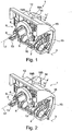
- Open-end spinning device 1 shown has a bearing device 2, with which it is limited pivotally mounted on a stationary, usually machine-length bearing axis 3.
- the in the Figures 1 and 2 For reasons of clarity, spinning rotor 7, not shown in more detail, is rotatably mounted with its rotor shaft 4 in a direct bearing device 5 and is driven by a circumferential, machine-length (not shown) tangential belt on which the rotor shaft 4 bears from below.
- the rotor housing 6, in which the spinning cup 11 of the spinning rotor 7 rotates at high speed during the spinning process, is closed by a cover element 8.
- the direct bearing device 5 and the rotor housing 6 form a rotor shaft bearing device 9, which is connected via a pivot axis 10 to a sliver opening device 12 of the open-end spinning device 1.
- the rotor shaft bearing device 9 is positioned in an inoperative position in which a brake member 13 abuts the rotor shaft 4, which is positioned at this time spaced from the machine-length, further circulating tangential belt.
- sliver opening device 12 In the sliver opening device 12, as usual, rotatably mounted an opening roller, which during the spinning operation, for example, by a machine-length Tangential belt is driven. Furthermore, a so-called sliver feed cylinder is rotatably mounted in the sliver opening device 12, the drive of which is effected in the exemplary embodiment via a single drive, for example a stepping motor.
- the axes of rotation of the opening roller and the sliver feed cylinder are arranged orthogonal to the axis of rotation 17 of the spinning rotor 7 during the spinning process.
- an upper cover 16 and a lower cover 15 are attached, which prevent too rapid contamination of the open-end spinning device 1.
- the upper cover 16 in this case has a connection socket 14, in which a holder 18, in the embodiment of FIGS. 1 and 3a , A holder 18 A is set interchangeable in each case.
- a relatively low installation height h for example, via a clip closure, a relatively short thread withdrawal tube 19 A set, which has a length I.
- FIG. 2 shows in perspective rear view of an open-end spinning device 1 for a workstation of an open-end rotor spinning machine, which operates in the so-called "Joint-Spinning-In” method and is equipped for this reason, for intermediate storage of the yarn with a thread as long as possible Fadenabzugsrschreibchen.
- the open-end spinning device 1 according to Fig. 2 corresponds to the holder 18 and the thread withdrawal tube 19 of the basis of the Fig.1 Open-end spinning device 1 described.
- Fig.2 can be seen in this embodiment on the terminal base 14 of the upper cover 16 interchangeably a holder 18 B set, the installation height H is well above the installation height h of the holder 18 A.
- the holder 18 B which has a relatively large installation height H, for example, via a clip closure, a relatively long thread withdrawal tube 19 B set, which has a length L.
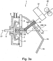
- the 3a shows in side view, partly in section like the Fig.1 , an open-end spinning device 1 for a workstation of an open-end rotor spinning machine, which is individually, preferably partially manually, spun.
- Such open-end spinning devices 1 are advantageously provided with a yarn clearer 21, and therefore require in the region between the mouth 22 of the yarn withdrawal tube 19A and a downstream yarn withdrawal device 20, some space, which through the use of a suitably adapted holder 18 A and an associated thread take-off tube 19 A is realized , For this reason, a holder 18 A is interchangeably fixed to the connection base 14 of the upper cover 16, which has a relatively small installation height h.
- a thread withdrawal tube 19 A set which also has a correspondingly short length I accordingly.
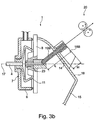
- the 3b also shows in side view and partly in section how the Fig.2 , an open-end spinning device 1 for a job of an open-end rotor spinning machine, which operates in the so-called "Joint-Spinning-In” method and is therefore equipped, for temporary storage of the Gamendes, with the longest possible Fadenabzugsrschreibchen.
- a holder 18 B is interchangeably fixed to the connection base 14 of the upper cover 16, which has a relatively large installation height H.
- a thread withdrawal tube 19 B is determined via a suitable fastening means, which has a relatively large length L.
- draw-off tubes 19 B with the long length L provide sufficient space for the twine to be temporarily stored in the event of a voltage drop and required for re-spinning in the "Joint-Spinning-In" method.
Landscapes
- Engineering & Computer Science (AREA)
- Mechanical Engineering (AREA)
- Textile Engineering (AREA)
- Spinning Or Twisting Of Yarns (AREA)
Claims (4)
- Procédé pour faire fonctionner un dispositif (1) de filature à bout ouvert pour un métier à filer à rotor à bout ouvert, comprenant un rotor à filer (7) dont la tige de rotor (4) est soutenue dans un ensemble palier (9) de tige de rotor et peut être sollicitée par une courroie tangentielle circulante s'étendant sur toute la longueur du métier, et dont la cloche de rotor (11), pendant l'opération de filature, tourne à haute vitesse de rotation dans un boîtier de rotor (6) qui peut être sollicité en dépression et qui peut être fermé par un élément (8) formant couvercle sur lequel sont disposés une buse (23) de sortie de fil ainsi qu'un tube (19A, 19B) de sortie de fil, sachant qu'un ensemble (20) de sortie de fil pouvant être entraîné de manière réversible est installé à distance de l'embouchure (22) du tube (19) de sortie de fil,
caractérisé en ce qu'un élément de recouvrement (16), disposé sur le dessus, du dispositif (1) de filature à bout ouvert est respectivement équipé d'un support remplaçable (18A, 18B), le dépassant, pour l'une des extrémités d'un tube (19A, 19B) de sortie de fil qui est raccordé par son autre extrémité à l'élément (8) formant couvercle dans la région de la buse (23) de sortie de fil, sachant que deux supports (18A, 18B), de dimensions différentes en ce qui concerne leur hauteur dépassant de l'élément de recouvrement (16) disposé sur le dessus, et le tube (19A, 19B) de sortie de fil dont la longueur (1, L) varie en fonction de la différence de hauteur, peuvent être respectivement alternativement fixés dans l'élément de recouvrement (16), et sachant qu'on utilise un tube (19A, 19B) de sortie de fil dont la longueur (1, L) est respectivement fonction de la méthode de début de filature qui est utilisée lors de la reprise de la filature avec les dispositifs de filature à bout ouvert du métier à filer à rotor à bout ouvert concerné. - Procédé selon la revendication 1, caractérisé en ce que, lorsqu'il est prévu d'utiliser la méthode dite « joint spinning in », on utilise des tubes (19B) de sortie de fil dont la longueur (L) est supérieure à la longueur (1) de tubes (19A) de sortie de fil qui sont employés lorsque les dispositifs (1) de filature à bout ouvert du métier à filer à rotor à bout ouvert sont exploités avec la méthode de début de filature individuel.
- Procédé selon la revendication 2, caractérisé en ce que, lorsqu'on utilise des tubes (19B) de sortie de fil pour la méthode dite «joint spinning in », on emploie des supports (18B) qui présentent une relativement grande hauteur d'installation (H), tandis qu'avec des tubes (19A) de sortie de fil qui sont employés lorsque les dispositifs (1) de filature à bout ouvert du métier à filer à rotor à bout ouvert sont exploités avec la méthode de début de filature individuel, on emploie des supports (18A) qui présentent une faible hauteur d'installation (h).
- Procédé selon la revendication 1, caractérisé en ce que les tubes (19A, 19B) de sortie de fil des dispositifs (1) de filature à bout ouvert sont respectivement clipsés dans un support (18A, 18b).
Applications Claiming Priority (1)
| Application Number | Priority Date | Filing Date | Title |
|---|---|---|---|
| DE102014008748.4A DE102014008748A1 (de) | 2014-06-12 | 2014-06-12 | Offenend-Spinnvorrichtung |
Related Parent Applications (1)
| Application Number | Title | Priority Date | Filing Date |
|---|---|---|---|
| DE102014008748 Previously-Filed-Application | 2014-06-12 |
Publications (2)
| Publication Number | Publication Date |
|---|---|
| EP2957663A1 EP2957663A1 (fr) | 2015-12-23 |
| EP2957663B1 true EP2957663B1 (fr) | 2017-03-08 |
Family
ID=53298075
Family Applications (1)
| Application Number | Title | Priority Date | Filing Date |
|---|---|---|---|
| EP15001402.5A Not-in-force EP2957663B1 (fr) | 2014-06-12 | 2015-05-08 | Méthode pour opérer un métier à filer à bout libre |
Country Status (3)
| Country | Link |
|---|---|
| EP (1) | EP2957663B1 (fr) |
| CN (1) | CN105316812B (fr) |
| DE (1) | DE102014008748A1 (fr) |
Families Citing this family (6)
| Publication number | Priority date | Publication date | Assignee | Title |
|---|---|---|---|---|
| JP6971915B2 (ja) * | 2018-06-05 | 2021-11-24 | 株式会社荏原製作所 | めっき方法、めっき装置、及び限界電流密度を推定する方法 |
| DE102019116278A1 (de) * | 2019-06-14 | 2020-12-17 | Saurer Intelligent Technology AG | Textilmaschine |
| DE102020101840A1 (de) * | 2020-01-27 | 2021-07-29 | Maschinenfabrik Rieter Ag | Fadenführungseinheit, Offenend-Rotorspinnmaschine und Verfahren zum Betreiben einer Spinnstelle |
| EP3919659B1 (fr) * | 2020-06-03 | 2023-02-15 | Saurer Spinning Solutions GmbH & Co. KG | Procédé de filage d'un métier à filer à rotor à bout libre et métier à filer à rotor à bout libre |
| DE102020124125A1 (de) | 2020-09-16 | 2022-03-17 | Saurer Spinning Solutions Gmbh & Co. Kg | Kreuzspulen herstellende Textilmaschine |
| CN117230550B (zh) * | 2023-10-27 | 2025-07-22 | 冠县鑫昌纺织有限责任公司 | 配有捻转保持元件的转杯纺纺纱装置 |
Family Cites Families (15)
| Publication number | Priority date | Publication date | Assignee | Title |
|---|---|---|---|---|
| GB1192377A (en) * | 1966-11-09 | 1970-05-20 | Tmm Research Ltd | Improvements relating to the Spinning of Textile Yarns |
| CH672800A5 (fr) * | 1986-03-19 | 1989-12-29 | Schlafhorst & Co W | |
| DE3635510C2 (de) | 1986-10-18 | 1995-10-26 | Schlafhorst & Co W | Verfahren und Einrichtung zur Außerbetriebnahme und darauffolgenden Wiederinbetriebnahme einer OE-Rotorspinnmaschine |
| DE3723504A1 (de) * | 1987-07-16 | 1989-01-26 | Schlafhorst & Co W | Drallstauelement fuer eine offenend-rotorspinnvorrichtung |
| US5323599A (en) * | 1988-04-08 | 1994-06-28 | W. Schlafhorst & Co. | Process and apparatus for producing hairiness in an open-end spinning yarn |
| JPH03193927A (ja) * | 1989-12-20 | 1991-08-23 | Asahi Chem Ind Co Ltd | 紡績用装置の仮撚用装置 |
| DE19544617B4 (de) * | 1995-11-30 | 2008-06-12 | Maschinenfabrik Rieter Ag | Adapter für Offenend-Spinnvorrichtungen |
| US5913806A (en) * | 1997-11-08 | 1999-06-22 | Rieter Ingolstadt Spinnereimaschinenbau Ag | Device to convey fibers to the collection surface of a spinning rotor |
| DE19749492A1 (de) * | 1996-11-16 | 1998-05-20 | Rieter Ingolstadt Spinnerei | Vorrichtung zum Zuführen von Fasern zu der Sammelfläche eines Spinnrotors |
| DE19709747B4 (de) * | 1997-03-10 | 2005-10-06 | Saurer Gmbh & Co. Kg | Vorrichtung zur Vorbereitung eines Anspinnvorgangs an einer Offenend-Spinnvorrichtung |
| DE19836073A1 (de) * | 1998-08-10 | 2000-02-17 | Schlafhorst & Co W | Faserkanalplatte für eine Offenend-Spinnvorrichtung |
| DE19915924B4 (de) * | 1999-04-09 | 2009-12-10 | Rieter Ingolstadt Gmbh | Fadenführungsrohr |
| DE19917968B4 (de) | 1999-04-21 | 2007-08-23 | Saurer Gmbh & Co. Kg | Serviceaggregat für eine Kreuzspulen herstellende Textilmaschine |
| DE10139075A1 (de) | 2001-08-09 | 2003-02-20 | Schlafhorst & Co W | Offenend-Rotorspinnmaschine |
| DE102005036485A1 (de) | 2005-08-03 | 2007-02-08 | Saurer Gmbh & Co. Kg | Offenend-Rotorspinnmaschine |
-
2014
- 2014-06-12 DE DE102014008748.4A patent/DE102014008748A1/de not_active Withdrawn
-
2015
- 2015-05-08 EP EP15001402.5A patent/EP2957663B1/fr not_active Not-in-force
- 2015-06-09 CN CN201510312581.7A patent/CN105316812B/zh active Active
Also Published As
| Publication number | Publication date |
|---|---|
| CN105316812B (zh) | 2017-09-22 |
| EP2957663A1 (fr) | 2015-12-23 |
| CN105316812A (zh) | 2016-02-10 |
| DE102014008748A1 (de) | 2015-12-17 |
Similar Documents
| Publication | Publication Date | Title |
|---|---|---|
| EP2957663B1 (fr) | Méthode pour opérer un métier à filer à bout libre | |
| DE10139072B4 (de) | Serviceaggregat zum Wiederanspinnen von Arbeitsstellen einer Offenend-Spinnmaschine | |
| DE102007056561A1 (de) | Kreuzspulen herstellende Textilmaschine | |
| EP2801646B1 (fr) | Procédé de fonctionnement d'un métier à filer à bout libre, du type filature à rotor | |
| WO2008043408A1 (fr) | Poste de travail d'une machine pour textile | |
| EP3312317B1 (fr) | Poste de travail d'une machine textile comprenant un dispositif de stockage de fil pneumatique et machine textile | |
| EP1749906A2 (fr) | Arrangement de rattachement pour une métier à filer à bout libre à rotor | |
| EP2657380A2 (fr) | Procédé et dispositif de fonctionnement de postes de travail d'un métier à tisser à rotor à extrémité ouverte | |
| EP2955143B1 (fr) | Machine textile semi-automatique fabriquant des bobines | |
| EP2966201A2 (fr) | Métier à tisser à rotor semi-automatique à extrémité ouverte | |
| EP3144418B1 (fr) | Procede d'adaptation d'une conception usine concernant une fabrication de lot de fil d'un metier a tisser a rotor a extremite ouverte | |
| DE102013014195A1 (de) | Behebung einer Fadenunterbrechung beim Wickeln eines Fadens auf eine Kreuzspule | |
| EP2192213B1 (fr) | Agrégat de service pour alimenter les postes de travail d'un métier à filer open end | |
| DE19917968B4 (de) | Serviceaggregat für eine Kreuzspulen herstellende Textilmaschine | |
| EP3533739B1 (fr) | Procédé de fonctionnement d'une machine textile et machine textile | |
| EP2682509B1 (fr) | Banc d'étirage pour un métier à tisser | |
| WO2008049486A1 (fr) | Procédé et dispositif d'utilisation d'une machine textile qui prépare des bobines croisées | |
| DE102015118987A1 (de) | Verfahren zum Betreiben einer Spinnmaschine mit einer vollautomatischen Anspinnvorrichtung sowie Spinnmaschine mit einer vollautomatischen Anspinnvorrichtung | |
| EP2251292B1 (fr) | Dispositif de paraffinage pour une machine textile fabriquant des bobines croisées | |
| DE102016108391A1 (de) | Verfahren zum Garnmassenanspinnen auf den Arbeitsstellen einer Rotorspinnmaschine und Einrichtung zu dessen Ausführung | |
| DE102007038871A1 (de) | Verfahren zum Anspinnen an Textilmaschinen mit einer Mehrzahl von Spinnstellen | |
| EP3909896A1 (fr) | Dispositif de filage et procédé de rattachement d'un fil | |
| EP2660376A1 (fr) | Dispositif de fabrication d'une penne permettant la rattache sur un dispositif de tissage à extrémité ouverte | |
| DE102014018635A1 (de) | Verfahren und Vorrichtung zum Betreiben einer Arbeitsstelle einer Kreuzspulen herstellenden Textilmaschine | |
| EP3919659B1 (fr) | Procédé de filage d'un métier à filer à rotor à bout libre et métier à filer à rotor à bout libre |
Legal Events
| Date | Code | Title | Description |
|---|---|---|---|
| PUAI | Public reference made under article 153(3) epc to a published international application that has entered the european phase |
Free format text: ORIGINAL CODE: 0009012 |
|
| AK | Designated contracting states |
Kind code of ref document: A1 Designated state(s): AL AT BE BG CH CY CZ DE DK EE ES FI FR GB GR HR HU IE IS IT LI LT LU LV MC MK MT NL NO PL PT RO RS SE SI SK SM TR |
|
| AX | Request for extension of the european patent |
Extension state: BA ME |
|
| 17P | Request for examination filed |
Effective date: 20160623 |
|
| RBV | Designated contracting states (corrected) |
Designated state(s): AL AT BE BG CH CY CZ DE DK EE ES FI FR GB GR HR HU IE IS IT LI LT LU LV MC MK MT NL NO PL PT RO RS SE SI SK SM TR |
|
| GRAP | Despatch of communication of intention to grant a patent |
Free format text: ORIGINAL CODE: EPIDOSNIGR1 |
|
| RIC1 | Information provided on ipc code assigned before grant |
Ipc: D01H 4/40 20060101AFI20161027BHEP |
|
| INTG | Intention to grant announced |
Effective date: 20161111 |
|
| GRAS | Grant fee paid |
Free format text: ORIGINAL CODE: EPIDOSNIGR3 |
|
| GRAA | (expected) grant |
Free format text: ORIGINAL CODE: 0009210 |
|
| AK | Designated contracting states |
Kind code of ref document: B1 Designated state(s): AL AT BE BG CH CY CZ DE DK EE ES FI FR GB GR HR HU IE IS IT LI LT LU LV MC MK MT NL NO PL PT RO RS SE SI SK SM TR |
|
| REG | Reference to a national code |
Ref country code: GB Ref legal event code: FG4D Free format text: NOT ENGLISH |
|
| REG | Reference to a national code |
Ref country code: CH Ref legal event code: EP Ref country code: AT Ref legal event code: REF Ref document number: 873613 Country of ref document: AT Kind code of ref document: T Effective date: 20170315 |
|
| REG | Reference to a national code |
Ref country code: IE Ref legal event code: FG4D Free format text: LANGUAGE OF EP DOCUMENT: GERMAN |
|
| REG | Reference to a national code |
Ref country code: DE Ref legal event code: R096 Ref document number: 502015000663 Country of ref document: DE |
|
| REG | Reference to a national code |
Ref country code: LT Ref legal event code: MG4D |
|
| REG | Reference to a national code |
Ref country code: NL Ref legal event code: MP Effective date: 20170308 |
|
| PG25 | Lapsed in a contracting state [announced via postgrant information from national office to epo] |
Ref country code: FI Free format text: LAPSE BECAUSE OF FAILURE TO SUBMIT A TRANSLATION OF THE DESCRIPTION OR TO PAY THE FEE WITHIN THE PRESCRIBED TIME-LIMIT Effective date: 20170308 Ref country code: NO Free format text: LAPSE BECAUSE OF FAILURE TO SUBMIT A TRANSLATION OF THE DESCRIPTION OR TO PAY THE FEE WITHIN THE PRESCRIBED TIME-LIMIT Effective date: 20170608 Ref country code: LT Free format text: LAPSE BECAUSE OF FAILURE TO SUBMIT A TRANSLATION OF THE DESCRIPTION OR TO PAY THE FEE WITHIN THE PRESCRIBED TIME-LIMIT Effective date: 20170308 Ref country code: HR Free format text: LAPSE BECAUSE OF FAILURE TO SUBMIT A TRANSLATION OF THE DESCRIPTION OR TO PAY THE FEE WITHIN THE PRESCRIBED TIME-LIMIT Effective date: 20170308 Ref country code: GR Free format text: LAPSE BECAUSE OF FAILURE TO SUBMIT A TRANSLATION OF THE DESCRIPTION OR TO PAY THE FEE WITHIN THE PRESCRIBED TIME-LIMIT Effective date: 20170609 |
|
| PG25 | Lapsed in a contracting state [announced via postgrant information from national office to epo] |
Ref country code: RS Free format text: LAPSE BECAUSE OF FAILURE TO SUBMIT A TRANSLATION OF THE DESCRIPTION OR TO PAY THE FEE WITHIN THE PRESCRIBED TIME-LIMIT Effective date: 20170308 Ref country code: SE Free format text: LAPSE BECAUSE OF FAILURE TO SUBMIT A TRANSLATION OF THE DESCRIPTION OR TO PAY THE FEE WITHIN THE PRESCRIBED TIME-LIMIT Effective date: 20170308 Ref country code: BG Free format text: LAPSE BECAUSE OF FAILURE TO SUBMIT A TRANSLATION OF THE DESCRIPTION OR TO PAY THE FEE WITHIN THE PRESCRIBED TIME-LIMIT Effective date: 20170608 Ref country code: ES Free format text: LAPSE BECAUSE OF FAILURE TO SUBMIT A TRANSLATION OF THE DESCRIPTION OR TO PAY THE FEE WITHIN THE PRESCRIBED TIME-LIMIT Effective date: 20170308 Ref country code: LV Free format text: LAPSE BECAUSE OF FAILURE TO SUBMIT A TRANSLATION OF THE DESCRIPTION OR TO PAY THE FEE WITHIN THE PRESCRIBED TIME-LIMIT Effective date: 20170308 Ref country code: LU Free format text: LAPSE BECAUSE OF NON-PAYMENT OF DUE FEES Effective date: 20170531 |
|
| PG25 | Lapsed in a contracting state [announced via postgrant information from national office to epo] |
Ref country code: NL Free format text: LAPSE BECAUSE OF FAILURE TO SUBMIT A TRANSLATION OF THE DESCRIPTION OR TO PAY THE FEE WITHIN THE PRESCRIBED TIME-LIMIT Effective date: 20170308 |
|
| PG25 | Lapsed in a contracting state [announced via postgrant information from national office to epo] |
Ref country code: RO Free format text: LAPSE BECAUSE OF FAILURE TO SUBMIT A TRANSLATION OF THE DESCRIPTION OR TO PAY THE FEE WITHIN THE PRESCRIBED TIME-LIMIT Effective date: 20170308 Ref country code: EE Free format text: LAPSE BECAUSE OF FAILURE TO SUBMIT A TRANSLATION OF THE DESCRIPTION OR TO PAY THE FEE WITHIN THE PRESCRIBED TIME-LIMIT Effective date: 20170308 Ref country code: SK Free format text: LAPSE BECAUSE OF FAILURE TO SUBMIT A TRANSLATION OF THE DESCRIPTION OR TO PAY THE FEE WITHIN THE PRESCRIBED TIME-LIMIT Effective date: 20170308 |
|
| PG25 | Lapsed in a contracting state [announced via postgrant information from national office to epo] |
Ref country code: PT Free format text: LAPSE BECAUSE OF FAILURE TO SUBMIT A TRANSLATION OF THE DESCRIPTION OR TO PAY THE FEE WITHIN THE PRESCRIBED TIME-LIMIT Effective date: 20170710 Ref country code: PL Free format text: LAPSE BECAUSE OF FAILURE TO SUBMIT A TRANSLATION OF THE DESCRIPTION OR TO PAY THE FEE WITHIN THE PRESCRIBED TIME-LIMIT Effective date: 20170308 Ref country code: SM Free format text: LAPSE BECAUSE OF FAILURE TO SUBMIT A TRANSLATION OF THE DESCRIPTION OR TO PAY THE FEE WITHIN THE PRESCRIBED TIME-LIMIT Effective date: 20170308 Ref country code: IS Free format text: LAPSE BECAUSE OF FAILURE TO SUBMIT A TRANSLATION OF THE DESCRIPTION OR TO PAY THE FEE WITHIN THE PRESCRIBED TIME-LIMIT Effective date: 20170708 |
|
| REG | Reference to a national code |
Ref country code: DE Ref legal event code: R097 Ref document number: 502015000663 Country of ref document: DE |
|
| PLBE | No opposition filed within time limit |
Free format text: ORIGINAL CODE: 0009261 |
|
| STAA | Information on the status of an ep patent application or granted ep patent |
Free format text: STATUS: NO OPPOSITION FILED WITHIN TIME LIMIT |
|
| PG25 | Lapsed in a contracting state [announced via postgrant information from national office to epo] |
Ref country code: DK Free format text: LAPSE BECAUSE OF FAILURE TO SUBMIT A TRANSLATION OF THE DESCRIPTION OR TO PAY THE FEE WITHIN THE PRESCRIBED TIME-LIMIT Effective date: 20170308 Ref country code: MC Free format text: LAPSE BECAUSE OF FAILURE TO SUBMIT A TRANSLATION OF THE DESCRIPTION OR TO PAY THE FEE WITHIN THE PRESCRIBED TIME-LIMIT Effective date: 20170308 |
|
| 26N | No opposition filed |
Effective date: 20171211 |
|
| REG | Reference to a national code |
Ref country code: IE Ref legal event code: MM4A |
|
| PG25 | Lapsed in a contracting state [announced via postgrant information from national office to epo] |
Ref country code: SI Free format text: LAPSE BECAUSE OF FAILURE TO SUBMIT A TRANSLATION OF THE DESCRIPTION OR TO PAY THE FEE WITHIN THE PRESCRIBED TIME-LIMIT Effective date: 20170308 |
|
| REG | Reference to a national code |
Ref country code: FR Ref legal event code: ST Effective date: 20180131 |
|
| PG25 | Lapsed in a contracting state [announced via postgrant information from national office to epo] |
Ref country code: LU Free format text: LAPSE BECAUSE OF NON-PAYMENT OF DUE FEES Effective date: 20170508 |
|
| REG | Reference to a national code |
Ref country code: BE Ref legal event code: MM Effective date: 20170531 |
|
| PG25 | Lapsed in a contracting state [announced via postgrant information from national office to epo] |
Ref country code: IE Free format text: LAPSE BECAUSE OF NON-PAYMENT OF DUE FEES Effective date: 20170508 |
|
| PG25 | Lapsed in a contracting state [announced via postgrant information from national office to epo] |
Ref country code: FR Free format text: LAPSE BECAUSE OF NON-PAYMENT OF DUE FEES Effective date: 20170531 |
|
| PGFP | Annual fee paid to national office [announced via postgrant information from national office to epo] |
Ref country code: CZ Payment date: 20180503 Year of fee payment: 4 Ref country code: DE Payment date: 20180521 Year of fee payment: 4 |
|
| PG25 | Lapsed in a contracting state [announced via postgrant information from national office to epo] |
Ref country code: BE Free format text: LAPSE BECAUSE OF NON-PAYMENT OF DUE FEES Effective date: 20170531 |
|
| PGFP | Annual fee paid to national office [announced via postgrant information from national office to epo] |
Ref country code: IT Payment date: 20180531 Year of fee payment: 4 |
|
| REG | Reference to a national code |
Ref country code: DE Ref legal event code: R081 Ref document number: 502015000663 Country of ref document: DE Owner name: SAURER SPINNING SOLUTIONS GMBH & CO. KG, DE Free format text: FORMER OWNER: SAURER GERMANY GMBH & CO. KG, 42897 REMSCHEID, DE |
|
| PG25 | Lapsed in a contracting state [announced via postgrant information from national office to epo] |
Ref country code: MT Free format text: LAPSE BECAUSE OF FAILURE TO SUBMIT A TRANSLATION OF THE DESCRIPTION OR TO PAY THE FEE WITHIN THE PRESCRIBED TIME-LIMIT Effective date: 20170308 |
|
| REG | Reference to a national code |
Ref country code: CH Ref legal event code: PL |
|
| PG25 | Lapsed in a contracting state [announced via postgrant information from national office to epo] |
Ref country code: LI Free format text: LAPSE BECAUSE OF NON-PAYMENT OF DUE FEES Effective date: 20180531 Ref country code: CH Free format text: LAPSE BECAUSE OF NON-PAYMENT OF DUE FEES Effective date: 20180531 |
|
| PG25 | Lapsed in a contracting state [announced via postgrant information from national office to epo] |
Ref country code: HU Free format text: LAPSE BECAUSE OF FAILURE TO SUBMIT A TRANSLATION OF THE DESCRIPTION OR TO PAY THE FEE WITHIN THE PRESCRIBED TIME-LIMIT; INVALID AB INITIO Effective date: 20150508 |
|
| PG25 | Lapsed in a contracting state [announced via postgrant information from national office to epo] |
Ref country code: CY Free format text: LAPSE BECAUSE OF FAILURE TO SUBMIT A TRANSLATION OF THE DESCRIPTION OR TO PAY THE FEE WITHIN THE PRESCRIBED TIME-LIMIT Effective date: 20170308 |
|
| PG25 | Lapsed in a contracting state [announced via postgrant information from national office to epo] |
Ref country code: MK Free format text: LAPSE BECAUSE OF FAILURE TO SUBMIT A TRANSLATION OF THE DESCRIPTION OR TO PAY THE FEE WITHIN THE PRESCRIBED TIME-LIMIT Effective date: 20170308 |
|
| REG | Reference to a national code |
Ref country code: DE Ref legal event code: R119 Ref document number: 502015000663 Country of ref document: DE |
|
| GBPC | Gb: european patent ceased through non-payment of renewal fee |
Effective date: 20190508 |
|
| PG25 | Lapsed in a contracting state [announced via postgrant information from national office to epo] |
Ref country code: CZ Free format text: LAPSE BECAUSE OF NON-PAYMENT OF DUE FEES Effective date: 20190508 |
|
| PG25 | Lapsed in a contracting state [announced via postgrant information from national office to epo] |
Ref country code: TR Free format text: LAPSE BECAUSE OF FAILURE TO SUBMIT A TRANSLATION OF THE DESCRIPTION OR TO PAY THE FEE WITHIN THE PRESCRIBED TIME-LIMIT Effective date: 20170308 |
|
| PG25 | Lapsed in a contracting state [announced via postgrant information from national office to epo] |
Ref country code: DE Free format text: LAPSE BECAUSE OF NON-PAYMENT OF DUE FEES Effective date: 20191203 Ref country code: IT Free format text: LAPSE BECAUSE OF NON-PAYMENT OF DUE FEES Effective date: 20190508 Ref country code: GB Free format text: LAPSE BECAUSE OF NON-PAYMENT OF DUE FEES Effective date: 20190508 |
|
| PG25 | Lapsed in a contracting state [announced via postgrant information from national office to epo] |
Ref country code: AL Free format text: LAPSE BECAUSE OF FAILURE TO SUBMIT A TRANSLATION OF THE DESCRIPTION OR TO PAY THE FEE WITHIN THE PRESCRIBED TIME-LIMIT Effective date: 20170308 |
|
| REG | Reference to a national code |
Ref country code: AT Ref legal event code: MM01 Ref document number: 873613 Country of ref document: AT Kind code of ref document: T Effective date: 20200508 |
|
| PG25 | Lapsed in a contracting state [announced via postgrant information from national office to epo] |
Ref country code: AT Free format text: LAPSE BECAUSE OF NON-PAYMENT OF DUE FEES Effective date: 20200508 |