EP2957709A2 - Système de sécurité permettant d'isoler les zones dangereuses d'une machine de forage, machine de forage pourvue d'un tel système de sécurité et procédé d'utilisation de ladite machine de forage - Google Patents
Système de sécurité permettant d'isoler les zones dangereuses d'une machine de forage, machine de forage pourvue d'un tel système de sécurité et procédé d'utilisation de ladite machine de forage Download PDFInfo
- Publication number
- EP2957709A2 EP2957709A2 EP15172967.0A EP15172967A EP2957709A2 EP 2957709 A2 EP2957709 A2 EP 2957709A2 EP 15172967 A EP15172967 A EP 15172967A EP 2957709 A2 EP2957709 A2 EP 2957709A2
- Authority
- EP
- European Patent Office
- Prior art keywords
- screen
- rotary
- antenna
- drilling
- machine
- Prior art date
- Legal status (The legal status is an assumption and is not a legal conclusion. Google has not performed a legal analysis and makes no representation as to the accuracy of the status listed.)
- Granted
Links
- 238000005553 drilling Methods 0.000 title claims description 125
- 238000000034 method Methods 0.000 title claims description 11
- 230000008569 process Effects 0.000 title claims description 11
- 230000033001 locomotion Effects 0.000 claims abstract description 49
- 238000006073 displacement reaction Methods 0.000 claims abstract description 16
- 238000009412 basement excavation Methods 0.000 claims description 13
- 230000000903 blocking effect Effects 0.000 claims description 11
- 238000013519 translation Methods 0.000 claims description 7
- 230000008602 contraction Effects 0.000 claims 1
- 230000004888 barrier function Effects 0.000 description 16
- 239000000463 material Substances 0.000 description 14
- 239000000243 solution Substances 0.000 description 12
- 230000004224 protection Effects 0.000 description 11
- 230000001360 synchronised effect Effects 0.000 description 9
- 238000009434 installation Methods 0.000 description 5
- 230000014616 translation Effects 0.000 description 5
- 239000004744 fabric Substances 0.000 description 4
- 238000003780 insertion Methods 0.000 description 4
- 230000037431 insertion Effects 0.000 description 4
- 239000004033 plastic Substances 0.000 description 4
- XLYOFNOQVPJJNP-UHFFFAOYSA-N water Substances O XLYOFNOQVPJJNP-UHFFFAOYSA-N 0.000 description 4
- 230000008901 benefit Effects 0.000 description 3
- 239000004568 cement Substances 0.000 description 3
- 238000004140 cleaning Methods 0.000 description 3
- 230000000694 effects Effects 0.000 description 3
- 238000002347 injection Methods 0.000 description 3
- 239000007924 injection Substances 0.000 description 3
- 238000012544 monitoring process Methods 0.000 description 3
- 230000000630 rising effect Effects 0.000 description 3
- 238000004904 shortening Methods 0.000 description 3
- 239000007921 spray Substances 0.000 description 3
- 229910000831 Steel Inorganic materials 0.000 description 2
- 230000005540 biological transmission Effects 0.000 description 2
- 230000006835 compression Effects 0.000 description 2
- 238000007906 compression Methods 0.000 description 2
- 239000011499 joint compound Substances 0.000 description 2
- 238000012423 maintenance Methods 0.000 description 2
- 239000002184 metal Substances 0.000 description 2
- 230000003287 optical effect Effects 0.000 description 2
- 238000012545 processing Methods 0.000 description 2
- 230000003014 reinforcing effect Effects 0.000 description 2
- 230000000284 resting effect Effects 0.000 description 2
- 239000010959 steel Substances 0.000 description 2
- 210000001015 abdomen Anatomy 0.000 description 1
- 230000009471 action Effects 0.000 description 1
- 230000003213 activating effect Effects 0.000 description 1
- 238000004026 adhesive bonding Methods 0.000 description 1
- 238000013459 approach Methods 0.000 description 1
- 238000007596 consolidation process Methods 0.000 description 1
- 238000010276 construction Methods 0.000 description 1
- 230000008878 coupling Effects 0.000 description 1
- 238000010168 coupling process Methods 0.000 description 1
- 238000005859 coupling reaction Methods 0.000 description 1
- 238000013016 damping Methods 0.000 description 1
- 230000001419 dependent effect Effects 0.000 description 1
- 238000005516 engineering process Methods 0.000 description 1
- 238000007667 floating Methods 0.000 description 1
- 231100001261 hazardous Toxicity 0.000 description 1
- 238000007689 inspection Methods 0.000 description 1
- 238000012986 modification Methods 0.000 description 1
- 230000004048 modification Effects 0.000 description 1
- 238000009527 percussion Methods 0.000 description 1
- 230000009467 reduction Effects 0.000 description 1
- 239000002689 soil Substances 0.000 description 1
- 230000001960 triggered effect Effects 0.000 description 1
- 238000002604 ultrasonography Methods 0.000 description 1
- 230000036642 wellbeing Effects 0.000 description 1
- 238000004804 winding Methods 0.000 description 1
Images






Classifications
-
- E—FIXED CONSTRUCTIONS
- E21—EARTH OR ROCK DRILLING; MINING
- E21B—EARTH OR ROCK DRILLING; OBTAINING OIL, GAS, WATER, SOLUBLE OR MELTABLE MATERIALS OR A SLURRY OF MINERALS FROM WELLS
- E21B41/00—Equipment or details not covered by groups E21B15/00 - E21B40/00
- E21B41/0021—Safety devices, e.g. for preventing small objects from falling into the borehole
Definitions
- the present invention concerns a safety system for drilling equipment particularly but not exclusively used in a drilling machine for controlling the dangerous area around the machine and for interrupting the dangerous manoeuvres of the machine itself.
- the present invention also concerns a drilling machine comprising the aforementioned safety system. More specifically, the safety system according to the present invention is used for preventing an operator from coming into contact with rotating or moving components of the drilling machine which are directly involved in the drilling process.
- the present invention is particularly suitable for being applied to drilling machines that, operating in several technological fields, can require the workers responsible for auxiliary services to carry out manual interventions in areas around the machine exposed to danger, in particular close to the guiding antenna or mast on which the rotating head or rotary slides and close to the drilling axis on which the shafts used for the excavation, mixing, jetting and driving-in processes are located.
- Drilling machines require interventions by workers that can generally be divided into three types: interventions of first mounting, maintenance interventions and interventions simultaneous to the work manoeuvres.
- dangerous area is meant to indicate the region of space around the guiding antenna where the rotating head slides and the region of space near the drilling area.
- the normal functioning mode i.e. the work mode
- the normal functioning mode is selected through a suitable selector and the start command is triggered.
- Such containment cages generally consist of one or more load-bearing frames, made through tubular elements or shaped metal sheets forming its external shape, and metallic or plastic grids, meshes or other screens taking up the area enclosed by such a shape.
- load-bearing frames can for example be hinged at points integral with the mast so as to be able to open by rotating on a horizontal plane, when the mast is arranged vertically, and leave free access to the dangerous area.
- barriers or “guards” in closed position i.e. in work condition, have substantial bulks that generally are greater in the horizontal direction than the shape of the rotary head or of the clamps in order to be able to receive the rotary itself inside the protected volume.
- Such bulks are linked to the need to delimit a sufficiently large hazardous area, i.e. to keep the operator sufficiently far away from the hazard represented by the rotating shafts.
- a further limitation of this solution is the increased weight of the drilling machine, with a consequent reduction of the stability due to the frontally overhanging positioning of such barriers.
- An alternative known solution consists of using sensitive devices, such as electrosensitive, photosensitive, laser, optical, radar, ultrasound or thermal devices. Such devices are arranged for producing a monitoring area that in turn at least partially comprises the dangerous area and to detect the presence and/or the passage of a body through such an area.
- sensitive devices such as electrosensitive, photosensitive, laser, optical, radar, ultrasound or thermal devices.
- Such devices are arranged for producing a monitoring area that in turn at least partially comprises the dangerous area and to detect the presence and/or the passage of a body through such an area.
- Such debris or sprays during their motion can, therefore, cross the monitoring areas by the sensitive devices. Such crossing can take place both from the excavation axis towards the outside of the dangerous area but also from outside of such an area towards the inside due for example to the bouncing of the debris against the parts of the machine, for example against the mast.
- a purpose of the present invention is to make a safety system for a drilling machine that overcomes the aforementioned drawbacks of the prior art, preventing direct contact with the rotary parts, eliminating at source the risk deriving in the dangerous area during the work steps of the machine, without limiting operating capabilities and at the same time allowing safe and easy access to the area of the tools during the loading or maintenance steps of the tools themselves.
- Such a purpose is achieved, in a first aspect of the present invention, with a safety system having the characteristics according to claim 1.
- a purpose is achieved with a drilling machine having the characteristics according to claim 8.
- a purpose is achieved with a process having the characteristics according to claim 14.
- a purpose is achieved with a process having the characteristics according to claim 15. Further characteristics of the device are the object of the dependent claims.
- the longitudinal sliding of the distal end ( 9 D, 90 C) along the guiding antenna (3) is driven by means of a linear actuator (61) and flexible transmission means (62, 64) connected to the elements of the screen (9, 90).
- the segment ( 9 A- 9 D, 90 A- 90 C) furthest from the rotary (5), called distal element ( 9 D, 90 C), is mounted on guides so as to be able to slide along the antenna (3).
- the segments ( 9 A- 9 D, 90 A- 90 C) of the extensible screen (9, 90) have mechanical resting abutments for defining the position of the elements when they are completely extended and/or for gathering them in a contracted configuration.
- the machine according to the invention comprises a first slider unit (82) fixed in correspondence with or in the proximity of the proximal end ( 9 A, 90 A, 900 A) of the screen (9, 90, 900), and a second slider unit ( 82 A) fixed in correspondence with or in the proximity of the distal end ( 9 D, 90 C, 900 B) of the extensible screen (9, 90, 900), and the first (82) and the second slider unit ( 82 A) are arranged for driving the screen (9, 90, 900) causing it slide, extend and retract along the guiding antenna (3).
- the first slider unit (82) is arranged for driving the proximal end ( 9 A, 900 A) of the screen (9, 900) making it slide according to a first direction (FT 1 ) transversal with respect to the guiding antenna (3)
- the second slider unit ( 82 A) is arranged for driving the distal end ( 9 D, 900 B) of the screen (9) making it slide according to a second direction (FT 2 ) parallel to the first direction (FT 1 ).
- the extensible screen comprises at least one segment provided with flexible or deformable walls capable of shortening and lengthening longitudinally to the axis of the segment itself and/or to the longitudinal axis of the drilling string.
- the extensible screen comprises a single segment, and the extensible screen is arranged for shortening and lengthening longitudinally thanks to the deformations of the segment itself.
- the at least one segment provided with flexible or deformable walls of the extensible screen comprises a tubular sleeve (900, 900 III , 900 IV ).
- such a tubular sleeve ( 900 IV ) can be formed by a strip wound in a helix so as to form a plurality of coils, and so that the edges of two adjacent coils partially overlap one another.
- the at least one segment provided with flexible or deformable walls of the extensible screen comprises at least one reinforcing ribbing or spiral (99) comprising a substantially rigid wire that winds in a helix.
- the at least one segment provided with flexible or deformable walls of the extensible screen comprises at least one substantially annular reinforcing ribbing or hoop (100).
- step F. 8 the extensible screen (9) is moved integrally with the rotating head (5) in the aforementioned transversal direction with respect to the guiding antenna (3).
- the document US 3078933 discloses a drilling machine provided with a horizontal auger enclosed in a telescopic cage; such a cage is not able to translate perpendicular to the axis of the auger.
- the drilling machine suitable for all excavation technologies by rotation, rotopercussion, vibration, driving-in and mixing and injection, suitable for being used for example to make piles, micro pile supports, tie rods or mechanical mixing and wholly indicated here with numeral 1, substantially comprises a base machine 2, for example mounted on tracks or wheels, which allow movement on the building site, a guiding antenna or mast 3, on which the drilling means slide, and a linkage 4 that allows the movement of the antenna with respect to the machine-base 2 to take it from an enclosed configuration, used for transportation, to a work configuration in which the mast 3 can be arranged vertically, inclined or horizontal.
- At least one rotating head 5, also called rotary, which applies the torque to the drilling string 6 and can slide along the antenna to cause the tool to move forwards or backwards in the excavation is mounted on the guiding antenna 3.
- an excavation system can be mounted that uses percussion and/or vibration in addition to rotation.
- the clamps 7 can, in an equivalent manner, comprise a clamp and an unscrewer.
- Figure 1 also shows a possible auxiliary winch used for moving the drilling accessories (like shafts 6 A or armatures 23 ) to be fixed to the hook 22 or to suitable lifting accessories.
- the rotary 5 can slide along the antenna 3 for example through the interposition of a slider unit 82 that can move longitudinally along the mast, for example guided on the suitable longitudinal guides 3 A and moved by a suitable known pull-push system, for example of the type with chains with cylinder or a geared motor.
- the guides 3 A integral with the mast 3 comprise elongated profiled elements in which it is possible to create a mechanical contrast on at least 3 sides.
- they are profiled with a closed, prismatic or "C-shaped" section.
- the rotary can therefore carry out longitudinal strokes to the antenna 3 between an upper end close to the head and a lower end close to the clamps 7.
- the safety system comprises a side displacement system 8 fixed, or in any case arranged for being fixed, to the guiding antenna 3 so as to move the rotary 5 both longitudinally to the guiding antenna 3, and in a transversal direction, and preferably perpendicular, to the antenna 3.
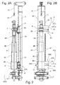
- the side displacement system 8 is arranged for moving the rotating head in a direction FT 1 perpendicular not only to the antenna 3, but also to the ideal plane passing through the axes of the guiding antenna 3 and of the shafts of the drilling string 6, as indicated in Figure 2 B .
- the side displacement system 8 can comprise a first slider unit or carriage 82 mounted on the antenna so that it can slide along it, being guided longitudinally on the guides 3 A.
- the first slider unit 82 in turn comprising:
- the guides 83 extend transversally, and more preferably perpendicularly, to the guiding antenna 3 and can be formed for example as a mechanical contrast prismatic guide , or a groove or furthermore a tubular (circular or prismatic) profile with elongated shape (in the transversal direction of movement) on which the second slider 80 is coupled and mutually guided.
- the rotary 5 can be fixed to the second slider 80, or include, in an irremovable manner, the second slider 80 itself.
- the side displacement system 8 also comprises an actuator that is used to drive the movement of the second slider 80.
- Said movement can for example be linear, like for example a hydraulic or pneumatic cylinder, or rotary - for example electric motor with screw and nut screw-type shaft - connected between the first slider 81 and the second slider 82, advantageously fixed to the first slider to facilitate the installation of the supply systems.
- the actuator 11 is a hydraulic cylinder arranged transversally, and more preferably perpendicularly, with respect to the axis of the antenna 3.
- Figure 2 A refers to a start of processing condition of the drilling machine 1, with the rotary 5 lifted with respect to the lower end stop position and with a drilling string 6 connected to the rotary.
- the string 6, which can comprise a plurality of shafts 6 A, receives the motion of rotation and of translation along the mast 3, from the rotary 5.
- this start of drilling condition shown in Figures 2 A and 2 B it is necessary to protect and/or isolate the dangerous area surrounding the drilling string 6 for preventing worksite personnel fro getting close and coming into contact with the moving parts involved in the drilling process. In particular, it is necessary to eliminate the danger of a person being able to get caught in the rotating shafts and consequently being pulled.
- the safety system of the present invention comprises an extensible screen 9, reversibly extendable and retractable along the guiding antenna 3, thus of variable length, in particular proportional to the stroke of the rotary 5 and which is driven so as to pass from a contracted or collected configuration 9' to an extended configuration 9, said longitudinal movement taking place by guiding a part thereof at the mast 3, in particular said part being the end opposite the part fixed to the rotary 5.
- the screen 9 encloses and surrounds the drilling string 6 completely or at least for a fair extension thereof.
- the screen 9 can be coaxial to the drilling string or even eccentric with respect to the drilling axis defined by the axis of the drilling string 6, and be equipped with circular cross sections (or in any case profiled with closed sections) and preferably have a length proportional to the stroke of the rotary 5 along the antenna 3, so as to cover preferably almost entirely the string 6 for its extension in length.
- the screen 9, in its lowest portion does not pass beyond the clamps 7 to contain its circumferential dimensions and reduce the bulks and therefore advantageously reaches a height near the clamps 7, preferably at a distance DAX not greater than 0-0.5 metres, and more preferably not greater than 0.2 metres from them (in particular from the one mounted at the top with respect to the other one(s)), and extends in a longitudinal direction preferably until it reaches close to the lower face of the body of the rotary 5, such as to completely or almost completely cover the longitudinal extension of the shafts 6 in front of the antenna 3.
- the upper end 9 A of the screen also called "proximal end” in the present description because of the two ends of the screen 9 it is the one closest to the rotary 5, in order to move in a synchronised manner with the movement of the rotary 5 imparted by the side displacement system 8 in the longitudinal direction on the antenna 3, can be connected in a direct manner to the side displacement system 8, in particular to the slider 82 or more advantageously to the rotary 5 or to the slider 80.
- the proximal end 9 A of the screen 9 is fixed integrally to the rotary 5 or to the slider 80 so as to follow, in a synchronised manner, at least the longitudinal sliding of the rotary along the guiding antenna 3.
- the upper end of the extensible screen 9 can be bolted or welded to the slider 80 or even to the rotary 5, so as to be pulled longitudinally (and laterally as will be explained hereafter), by the motion of the slider 80.
- the upper end 9 A of the extensible screen 9 can be held by a cable or other flexible means driven by a winch or other rotary actuator (not shown) fixed to the antenna 3.
- such a lower end can be kept at a predetermined axial height, and in particular at a minimum height above the clamps 7, independently from the motion and from the position of the rotary 5 and of the side sliding system 8.
- said lower end 9 D can be rested on a lower mechanical abutment or be directly rested on the clamps 7.
- the attachment of the upper end 9 A of the screen 9 to the rotating head 5 and/or to the slider 80 makes the safety system easier to install on different types of machines, in general simplifies the mechanical and circuit construction of the system and makes it easier to keep it permanently mounted on the drilling machine 1 during a large number of manoeuvres and operating situations.
- the screen 9 comprises a plurality of segments, in particular:
- the antenna 3 is shown vertical but it should be understood that in the various operative conditions it can be inclined frontwards, backwards or sideways with respect to the base machine 2.
- the segments 9 A, 9 B, 9 C, 9 D of the screen 9 are shown sectioned in Figure 2 A in order to allow the drilling string 6 that passes inside them using the suitable linkage 4 for positioning the antenna 3 to be seen. As shown in such a Figure, they can have closed cross sections so as to completely contain and surround the drilling string 6.
- the segments 9A, 9B, 9C and 9 D can be made with progressively increasing cross sections, so as to be able to be inserted inside one another in coaxial position and in a mutually sliding manner in the longitudinal direction forming a telescopic-type assembly.
- At least the segment 9 A closest to the rotating head 5 has an average or maximum diameter or more generally outer width, according to a direction parallel to the ideal plane passing through the axes of the guiding antenna 3 and of the shafts of the drilling string 6 ( Figure 2 B ), not greater than the maximum diameter or outer width of the rotary 5, so as to reduce the overall bulk of the screen 9 and facilitate the manoeuvres of the machine 1 during drillings in restricted spaces, like for example in urban areas.
- Each segment as can be seen in Figure 2 A , is preferably equipped with upper and lower edges or abutments that act as mechanical stops for the relative sliding of each segment with respect to the one immediately inside and with respect to the one immediately outside. In this way, the segments are prevented from slipping out and decoupling.
- the edges or abutments can also be dismountable, for example bolted, in order to facilitate the insertion of a segment of screen inside the other and then remountable once insertion has been carried out.
- the segments 9 A, 9 B, 9 C and 9 D of the telescopic screen can be made of rigid material, preferably of the metallic, light or lightened type, of low thickness.
- each segment 9 A- 9 D can be made from perforated metal plates or from gratings with small-sized holes, preferably no larger than 20 mm to prevent the fingers of a worker from entering but at the same time allow the shafts to be visible from the outside when they are in rotation and to allow the possibility of material coming out from the inside (for example the drilling debris) or allow easy cleaning from the outside.
- they can be made of plastic material in order to further reduce the weight and possibly be transparent to increase internal visibility.
- plastic material in order to further reduce the weight and possibly be transparent to increase internal visibility.
- there can also be a combination of the previous solutions described.
- the side displacement system 8 also comprises a second slider unit 82 A mounted on the antenna so that it can slide along it.
- the second slider unit 82 A preferably in turn comprises:
- the lower or distal segment 9 D is advantageously fixed to the fourth slider 80 A or be an integral part thereof or further more contain the abutments for coupling with the guides 83 A to carry out the side movements.
- the slider 80 A can be driven by an actuator 11 A that can for example be linear, like for example a hydraulic or pneumatic cylinder, or rotary - for example electric motor with screw and nut screw-type shaft - mounted on the third slider 81 A.
- an actuator 11 A can for example be linear, like for example a hydraulic or pneumatic cylinder, or rotary - for example electric motor with screw and nut screw-type shaft - mounted on the third slider 81 A.
- the second slider unit 82 A slides as a whole along the same guides 3 A along which the first slider unit 82 slides, if necessary using guide means such as rollers or sliding blocks to avoid wear.
- the function of the second slider unit 82 A is to maintain the coaxiality of the lower section of the screen 9 with the upper rotary and therefore with the drilling string 6, avoiding translations or misalignments of the screen elements 9 B, 9 C and 9 D on the plane perpendicular to the longitudinal axis of the antenna 3.
- the function of the guide means of the second slider unit 82 A is to prevent, when the antenna 3 is oriented with strong inclination with respect to the vertical, the extensible screen 9 from tending to belly, i.e. to be arranged in a deformed configuration according to a curved line. Indeed, in such a deformed configuration the segments of the screen 9 could come into contact with the string of rotary shafts 6 or they could tend to jam together preventing the telescopic movement.
- the segments of the screen 9 in the abutment parts will also be partially guided with respect to one another so as to reduce the flexing due to its own weight. If this is not sufficient, many guides at the mast 3 can be inserted and connected to other segments of the screen 9.
- the slider units 82, 82 A belonging to the side displacement system 8 are preferably dismountable from the elements of the screen 9 A, 9 B, 9 C or 9 D, for example bolted, in order to facilitate the insertion of one screen segment inside the other and then remountable once insertion has been carried out.
- the distal screen 9 D can quickly decouple from the antenna 3, dismounting one of the two attachment systems that make it integral either with the slider 80 A or with the slider 81 A.
- the dimensions of the section of the most inner screen segment are such as to be able to house the shafts of the drilling string and the floating or system for damping and motion transmission to the shafts 6 from the rotary 5, in directions perpendicular to the antenna 3.
- the lower screen segment 9 D can be driven/motorised in a first variant of motorisation through a system with at least one motorised pinion 41 that engages on at least one rack 42 integral with the antenna 3 and parallel to the guides 3 A.
- Said motorised pinion is preferably mounted, or in any case constrained to the slider unit 82 A that moves slidably guided along the antenna 3 and thus substantially parallel to the mounting direction of the rack 42.
- the rack 42 can be equivalently replaced for example by a roller chain.
- two racks 42' and 42" Figure 2 B ) they will preferably be mounted opposite with respect to the longitudinal middle plane of the antenna 3.
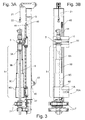
- a safety device can have a second type of motorisation, made through a flexible means (cable or chain) in a closed loop (with two branches, an upper one for lifting and a lower one for lowering).
- the rotation actuator 43 can be a winch or a geared motor.
- the actuator 43 is a winch with two cable branches, wherein the upper branch 44 for lifting and the lower branch 45 for lowering, wind/unwind in a synchronised manner on the same drum.
- the upper cable branch 44 is relayed through an upper pulley 46 fixed to the antenna 3 or to the upper head and connects to the screen 9 D, in particular in an upper area thereof or directly to the slider unit 82 A.
- the lower cable branch 45 is relayed through at least one lower pulley 47 fixed to the antenna 3 and connects to the screen 9 D and in particular to a lower area thereof or to the slider unit 82 A. In this way, if the actuator 43 is not actuated, the slider unit 82 A and therefore the lower screen 9 D stay in a fixed position with respect to the antenna 3 and such a position is maintained independently from the motion of the rotary 5.
- the safety system also comprises a sensor that detects the position of the distal end 9 D of the screen 9; more specifically, such a sensor can detect the completely extended configuration of the screen 9, when the lower screen 9 D is at the desired lower end, close to the clamps 7.
- Such a position at the minimum height i.e. at a height DAX no greater than 200 millimetres with respect to the upper face of the clamps, ensures that the string of shafts 6 is covered by the extensible screen 9 and that therefore it is inaccessible to the operator of the machine or to other people during all of the operative drilling steps. In such a position, it is therefore in safe conditions and the danger of parts of the body getting caught or making contact with the moving parts 6 involved in the drilling is eliminated.
- the drilling machine 1 can work in normal operating mode allowing the rotation of the string 6 and the advancing of the rotary 5.
- the sensor When the lower screen segment 9 D is lifted, the sensor detects such movement and generates a control signal that directly, or for example through a suitable logic unit 17 (shown in Figure 1 ) immediately commands all the dangerous manoeuvres to stop, in particular at least the rotation of the shafts, so as to protect the well-being of the operator; after this the logic unit 17 can for example automatically command the passage to safe operation of the machine, or simply enable it, leaving it at the operator's discretion whether to manually command the passage to safe operation of the machine or to return to normal operation.
- a suitable logic unit 17 shown in Figure 1
- the sensor fixed to the mast 3, can be of different types and can be installed in different positions of the machine, ensuring the same safety function.
- the sensor is a microswitch or a proximity sensor fixed at a suitable height on the antenna 3 so as to be activated by an abutment part of the screen 9 D, or rather by the slider unit 82 A.
- the senor can be an absolute encoder mounted on the rotary actuator 41 or 43 to read the rotations of the drum and thus derive the longitudinal position of the slider unit 82 A and thus of the screen 9.
- a control unit 17 e.g. a PLC
- Other variants of the sensor like those of the contactless type (for example laser and magnetic) are considered equivalent for the purpose.
- the actuator 41, 43 of the screen is not actuated and therefore the lower screen 9 D remains at a constant height with respect to the clamps 7.
- the upper and intermediate screen elements ( 9 A, 9 B and 9 C) slide with synchronised movement with respect to the rotary 5, collapsing towards the lower part of the antenna 3 and reducing the overall length of the screen 9 to the minimum closure size.
- the intermediate screen elements 9 B and 9 C progressively descend inside the lower element 9 D and thanks to its lower lips that act as scrapers also carry out cleaning of the inner wall of the screen 9 C.
- the screen 9B descends inside the screen 9 C until it goes into mechanical abutment through suitable abutments.
- the screen segment 9 A moves in the longitudinal direction to the antenna in a synchronised manner with the rotary 5 and with the slider unit 82.
- the height (in the longitudinal direction to the antenna) of the screen elements 9 A, 9 B, 9 C and 9 D is suitably selected so that in this configuration, the presence of the screen 9 does not reduce the useful stroke of the rotary and does not obstruct its motion.
- the screen 9 can be installed on a machine that originally lacked it, without such installation reducing the stroke of the rotary.
- the height of the screen elements sized in the manner just described implicitly determines the number of intermediate elements 9 B, 9 C necessary to allow a variation in length of the screen 9, between the completely contracted configuration and the completely extended configuration, equal to the stroke of the rotary 5.
- values of such a height can vary between 0.5 metres and 1.5 metres.
- the lifting of the lower screen 9 D is detected by the sensor that is activated, thus sending off a command signal and can act directly on the actuators of the rotary 5 to immediately stop at least the rotation of the drilling string.
- the sensor can simultaneously block both the rotation of the shafts and the axial sliding of the rotary 5 along the antenna.
- the command signal generated by the triggering of the sensor can be sent to a control unit 17 that as well as commanding at least the stopping of the rotation of the drilling string, can automatically manage multiple additional safety functions such as blocking the longitudinal sliding of the rotary 5 or emitting a sound or light warning signal; alternatively, the logic unit 17 can limit itself to enabling such additional safety functions, giving the possibility for an operator to activate them, or not, manually.
- the screen 9 D while rising, progressively encapsulates the intermediate screens 9 C and 9 B.
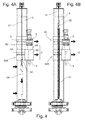
- the lower screen 9 D in its lower part is equipped with a horizontal edge that while rising progressively comes into contact with the lower edge of all of the intermediate and upper elements of the screen 9 pulling them up until the screen 9 is brought into the completely contracted condition 9' visible in Figure 4 whereas the edge with the upper segments resting on it is visible in Figure 10 .
- the lower edge of the screen 9 D partially closes the lower face of the screen and has an opening of slightly larger diameter than that of the shaft 6.
- the lower edge thus acts as a screen against the debris rising from the excavation and at least partially obstructing the rise of the debris in the screen.
- the lower edge of the element 9 D can be concave towards the base of the antenna.
- the concave shape allows the debris and the debris to be reflected towards the base of the antenna and allows the radius of the area in which they fall to be limited.
- At least one linear actuator 11 driving the lateral or transversal movement of the rotary, in a rigid manner pulls the screen 9 that slides laterally and in a guided manner with respect to the slider unit 82 A.
- the side displacement system can be actuated in a coordinated manner both by the actuator 11 and by the linear actuator 11 A.
- the transversal movement can be required also to carry out a loading of the shaft 6 A through the use of mechanized loading means installed on the machine 1 or through external mechanized loading means, which in some cases must be able to have free access over the entire front of the antenna 3 in order to be able to operate.
- mechanized loading means installed on the machine 1 or through external mechanized loading means, which in some cases must be able to have free access over the entire front of the antenna 3 in order to be able to operate.
- the screen 9 can be lowered to protect a possible shaft 6 that is connected on the rotary.
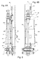
- Figure 5 shows the end of drilling configuration in which the rotary and the screen 9 are translated laterally without being lifted in height, to save time, particularly when the shafts 6 must be extracted from the hole using the service cable 21 or lifting means outside of the machine (used to remove many shafts together, without having to dismount them all).
- Figure 6 again shows a first embodiment of the safety system described with a third variant of motorisation consisting of a linear actuator or cylinder 61 (hydraulic, electric or pneumatic) that moves the screen 9 through a cable relay system 62 and 64.
- the actuator is connected at the bottom to the lower screen 9 C and at the top to the intermediate screen 9 B.
- the stroke of the rotary is shorter or the length of the segments is greater and therefore the number of them necessary to cover the entire stroke, when completely extended, is less than those shown in Figure 2 . Therefore, the distal element, in the case of Figure 6 is 9 C, whereas in Figure 2 it was 9D.
- the cable 62 is fixed at one end to the upper screen 9 A and at the other end to the lower part of the lower screen 9 C.
- the cable 64 is fixed at the top of the screen 9 A or directly to the rotary 5 or to the slider 80 or furthermore to the slider unit 82, and at the other end to the upper part of the lower screen 9 C. Passing from a completely extended configuration to one in which the actuator is retracted, the lower 9 C and intermediate screen 9 B are moved by cable relays 62 and 64 passing to the completely contracted configuration.
- the extensible screen 900, reversibly extendable and retractable along the guiding antenna 3 can consist of a single segment made with walls of a flexible or deformable material capable of shortening and lengthening longitudinally to its own axis and/or to the longitudinal axis of the drilling string when subjected to axial compression or traction.
- Said single segment made of flexible or deformable material can thus pass from a contracted or collected configuration 900' (visible in Figure 13 B ) to an extended configuration 900 (visible in Figure 13 A ).
- Examples of walls of a flexible or deformable material can be a wall in metallic mesh, a fabric sock, a tubular sheath in plastic material or in rubber.
- Said screen 900 comprises a proximal end 900 A and a distal end 900 B.
- the end 900 A can be substantially similar to the upper end of the screen 9 A of Figure 2
- the end 900 B can be substantially similar to the lower end of the screen 9 D of Figure 2 , with the important difference that in the embodiment of Figure 13 the proximal end 900 A and the distal end 900 B belong to the same single segment of the screen 900.
- the proximal end 900 A of the screen 900 is fixed integrally to the rotary 5 or to the first slider unit 82 to follow in a synchronised manner at least the longitudinal sliding of the rotary along the guiding antenna 3.
- the lower or distal end 900 B of the screen 900 is preferably fixed to the second slider unit 82 A and advantageously fixed to the fourth slider 80 A.
- the second slider unit 82 A or preferably the fourth slider 80 A are equipped with a plate or frame 96 that extends in a direction perpendicular to the antenna extending around the drilling axis for a radial bulk at least equal to that of the screen 900.
- the plate 96 has a central hole with a sufficient diameter to allow the passage of the string of shafts 6 and the passage of drilling debris. Such a plate 96 is fixed to the distal end 900 B of the screen 900.
- the second slider unit 82 A allows the lower section 900 B of the screen 900 and the plate 96 to be kept coaxial with the upper rotary and thus with the drilling string 6, even when the rotary translates laterally with respect to the antenna 3, avoiding misalignments of the screen 900 on the plane perpendicular to the longitudinal axis of the antenna 3.
- each winder 97 has a drum for accumulating cable and can be equipped with an inner spring, for example a coil spring, which allows the cable 98 to always be kept under tension. Possibly, the coil spring can be replaced by an electric or hydraulic motor that takes care of keeping the cable 98 under tension.
- each winder 97 allows the unwinding or release of the cable 98.
- each winder 97 recovers or rewinds the cable 98 and accumulates it in the drum.
- On the plate or frame 96 at least three winders are fixed, arranged so that the three cables 98, if observed in plan, are the same radial distance from the drilling axis, or rather are on a circle of smaller radius with respect to the radius of the screen 900, and arranged equally angularly spaced, or rather 120° apart from one another. It is also possible to fix many winders 97, for example four spaced apart by 90° or six spaced apart by 60° and so on.
- a screen 900 with a substantially cylindrical shape with closed cross section, or alternatively with a substantially C-shaped cross section or in any case such as to contain and surround the drilling string 6.
- the weft of such a mesh or fabric must be sufficiently dense, i.e. it must leave sufficiently small empty spaces, such as to prevent the entry of an operator's fingers but at the same time make it possible to see from the outside when the shafts are in rotation and the possibility of making material come out from inside (for example the drilling debris) or to allow easy cleaning from the outside.
- the screen 900 In the case in which the screen 900 is made of rubber it can have a "bellows" shape so as to be able to vary its own length.
- the extensible screen 900 is mounted outside the cables 98, so that they keep it radially distanced from the string of shafts 6. In the condition with the screen extended, as shown in Figure 13 A , it takes up an almost cylindrical shape with diameter not greater than the bulk of the rotary 5 but sufficiently large to encapsulate the cables 97 and the material from which such a screen is made takes up an almost rectilinear extended shape.
- a spiral or helix 99 for example formed from a metallic or plastic rod that winds up, forming coils that wind around the drilling axis so that each coil, if seen in plan, includes all of the cables 97 inside it and is externally tangent to the cables 97, still remaining inside the screen 900.
- the spiral 900 is thus arranged between the cables and the screen in a radial direction with respect to the axis of the shafts 6.
- This elastic spiral 99 contributes to maintaining the desired shape of the screen, ensuring its distance from the shafts even when the antenna is laterally inclined.
- This spiral 99 can also be connected to the screen 900 by sliding inside through holes formed on the screen itself.
- the upper and lower end of the spiral 99 can be fixed, respectively, to the rotary 5 and to the plate 96.
- the screen 900 behaves like a sleeve and tends to sag forming folds or creases that make it possible to accumulate the material of the screen in a contracted configuration 900' shown in Figure 13 B .
- the cables 97 ensure that such folds form towards the area outside the cables, thus further from the shafts 6.
- the spiral 99 is compressed and reduces the pitch of its coils to take up a shorter configuration, whereas the cables 98, which are inside the spiral 99 prevent it from taking up a laterally deviated configuration.
- Figure 14 A further and tenth embodiment is shown in Figure 14 .
- the solution of Figure 14 again foresees an extensible screen 900 III , reversibly extendable and retractable along the guiding antenna 3, which can consist of a single segment made with flexible or deformable material that makes it possible to vary the longitudinal dimension of the screen when it is subjected to a force, of traction or of compression, in a direction parallel to the longitudinal axis of the drilling string.
- the proximal end 900 A is connected to the upper slider unit 82 and the distal end 900 B is connected to the second slider unit 82 A.
- the difference with respect to the solution of Figure 13 consists of the fact that now the winders 97 are arranged so that the cables 98 slide outside the screen 900 III , i.e. at a greater radial distance with respect to the drilling axis. In order to keep the screen 900 III guided the spiral 99 is no longer present but it is possible to use hoops 100.
- These hoops 100 are substantially formed from a ring to which a plurality of guiding handles are fixed radially, arranged outside the ring itself.
- the ring of the hoop 100 has an inner diameter roughly corresponding to the diameter of the screen 900 III .
- a plurality of hoops 100 is fixed outside the screen 900 III at regular intervals along the axial dimension of the screen itself, for example gluing the rings of the hoops to the screen or making through hole on the screen inside which it is possible to pass the rings of the hoops 100.
- Each hoop 100 has a number of handles equal to the number of cables 98 intended to be used, for example three, four or six.
- Each handle has a through hole inside which the cable 98 can be slidably inserted, so that the hoop can slide with respect to the cables.
- the hoops are arranged perpendicular to the drilling axis, with the centre of the hoop positioned practically on the drilling axis, and they are kept in such a position thanks to the fact that they are guided on the cables 98 that in turn are arranged equally angularly spaced from the drilling axis.
- the hoops thus keep the screen distant from the shafts 6, even when the antenna 3 is inclined with respect to the vertical and give the screen itself a preferably cylindrical shape.
- the screen 900 III during this step behaves like a sleeve and tends to sag forming folds and creases that allow the material of the screen to accumulate in a contracted configuration 900' shown in Figure 14 B .
- FIG. 15 A further and eleventh embodiment is shown in Figure 15 .
- the extensible screen 900 IV reversibly extendable and retractable along the guiding antenna 3, consists of a single segment and in greater detail is made substantially as a coil spring.
- the coil springs preferably consist of a strip of harmonic steel that is wound around an axis creating concentric coils of increasing diameter, each of which partially covers the previous coil preferably also when the spring is in extended condition.
- the spring takes up a cone shape with the walls completely closed, thanks to the juxtaposition of the various coils.
- the screen 900 IV therefore has a proximal end 900 A with a greater diameter and a distal end 900 B with a smaller diameter.
- the elasticity of the harmonic steel tends to keep the coils in extended position, as can be seen in Figure 15 A , i.e. with the minimum axial juxtaposition and therefore with the maximum length of the spring.
- the juxtaposition of the coils and the conical shape of the spring also ensures that the coils are mutually guided in one another maintaining the rectilinear configuration of the spring without the need for external guides.
- the coil spring When the coil spring is compressed, the coils tend to slide with respect to one another in the axial direction, thanks to the fact that they have increasing diameters, increasing their axial juxtaposition and reducing the overall length of the spring.
- the spring always maintains a closed and continuous perimetric shape. It is thus possible to mount the coil spring, which forms the screen 900 IV , in coaxial position to the drilling axis by selecting a minimum diameter of the spring that is such as to contain the shafts 6 and that allows the debris to be discharged and at the same time allows a maximum diameter of the spring to be selected that does not jut with respect to the bulk of the rotary 5.
- the proximal end 900 A is connected to the rotary or to the upper slider unit 82 through a flange 100 A that partially inserts in the spiral
- the distal end 900 B is connected to the lower slider unit 82 A through a flange 100 B that partially inserts in the spiral.
- the coil spring of the screen 900 compresses staying coaxial to the shafts 6 until it reaches a contracted configuration 900 IV , as shown in Figure 15 B .
- the coil spring therefore prevents access to the shafts 6 during the work steps.
- the safety system comprises a sensor that detects the position of the distal end 900 B of the screen 900, in a totally analogous manner to what has already been described in the first embodiment. More specifically, such a sensor can detect the completely extended configuration of the screen 900, when the lower screen 900 B is at the desired lower end, close to the clamps 7.
- a screen made with a single flexible element made from fabric or mesh has the advantage of being lighter with respect to a screen with multiple rigid segments, and this case promote the stability of the machine.
- the extensible screen comprises a single segment, like for example in the embodiments of Figures 13 A, 13 B , 14 A, 14 B , 15 A, 15 B
- the latter in configuration of maximum extension has an overall length preferably equal to or greater than 2 metres, and preferably comprised between 2 metres and 10 metres, more preferably comprised between 2 metres and 8 metres or between 2-6 metres.
- Figure 7 shows a second embodiment, also motorised like the second variant already described in Figure 3 and with the same modes of actuation, therefore we will not repeat it.
- a difference with respect to the first embodiment described consists of the fact that the screen 90 instead of being laterally mobile like the screen 9, and in phase with the movement of the rotary 5 with respect to the first slider 81, as shown for example in Figures 4 and 5 , it is again position so as to always contain the drilling string 6 and it is not equipped with this transversal translation movement.
- the second slider unit 82 A can comprise the third slider 81 A, mounted so as to be able to slide along the guiding antenna 3 for example along suitable sliding guides, but lack the fourth slider 80 A.
- the screen 90 consists of a plurality of segments 90 A, 90 B, 90 C, totally analogous to the corresponding ones 9 A, 9B, 9 C described in the previous Figures (wherein 90 C, in this case being the lower screen, is comparable to 9 D of Figures 2 to 5 , and to 9 C of Figure 6 ) .
- the upper screen 90 A is advantageously fixed to the slider unit 82, or as described earlier it can be indirectly connected with flexible tensioning means that reach the screen 9 A from the high position of the antenna 3 (thus capable of keeping the screen 9 A always lifted and in the vicinity of the rotary, e.g. stopping on an abutment fixed to the rotary 5 or to the slider unit 82 ).
- the upper screen 90 A In the more difficult case in which the upper screen 90 A is fixed to the rotary 5 or to the slider 80, it must be an attachment capable of keeping the screen 90 suspended but at the same time of releasing the lateral movement of the rotary 5 with respect to the upper screen 90 A, so as to allow the movement thereof.
- the distal segment 90C in this case the lower one, as already illustrated in the previous configuration will be guided to the mast 3 through a carriage 81 A or more simply with at least one support arm among 92 and 93 (in Figure 7 both are represented) that are guided on the same guides 3 A of the mast 3 on which the carriage 81 is also guided, or on additional guides 94 fixed to the sides of the mast 3.
- the guides to the mast 3 can also be fixed on the intermediate elements, as shown in Figure 7 for the intermediate screen 90 B .
- the wire-like guide 91 will be positioned in the higher part of the screen so that when the screen 90 passes from the extended configuration 90 to the compressed configuration 90', the guides 91 go into a pack on the guides 92, optimising the minimum length in bulk totally closed.
- a sensor arranged at the base of the mast 3 notices the presence of the lower screen 90 C and enables normal drilling so long as said screen is not lifted by a motor means.
- Figure 8 shows a partial side and front section of said safety system in which the screen 90 surrounds on one side the drilling string 6 and on the opposite side it has an elongated shape so as to allow the lateral movement of the rotary 5 on the carriage 81.
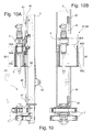
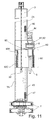
- the retractable screen 90 as shown in Figures 8 A, 8 B , 9, 10 A, 10 B , 11, 12, can have substantially elongated cross sections, preferably rectangular with semi-circular ends, i.e. with the so-called "obround" shape; in this case, the retractable screen 90 is longitudinally guided to the guiding antenna 3 so as not to be able to move perpendicularly or more generally transversally to the antenna 3, and only moves the rotating head 5 laterally.
- the elongated cross sections are advantageously oriented in the direction of the lateral movement FT 1 of the rotary.
- said lateral movement of the rotary 5 is always represented in the Figures towards the left, but it is totally analogous to that to the right.
- Figure 8 A it is possible to see the lower attachment points 48 of the flexible elements forming part of the upper branch 44 to the lower screen 90 C and the lower attachment point 49 of the lower branch 43 of the flexible element.
- the maximum external width at least of the proximal end or of the proximal segment 9 A considered in the ideal plane passing through the axes of the antenna 3 and of the drilling string is preferably no greater than the maximum external width of the rotating head 5 in the same ideal plane, so as to reduce the overall bulks of the screen 9 and increase the ease of manoeuvre of the machine 1 in small spaces.
- Figure 9 shows the rotary 5 in an end of drilling configuration, with the screen 90 in compressed or collected configuration 90', at the base of the antenna close to the clamps 7.
- Figure 10 shows the rotary 5 in a raised configuration, typically in the shaft loading step, with the screen 90 in compressed or collected configuration 90', at the top of the antenna.
- the loading can take place manually by inserting the shaft 6 A beneath the screen since said screen 90 in contracted configuration 90' no longer hampers the shaft 6 that always remains connected (also called “balancing rod") to the rotary 5 and that is used to arrive between the two clamps 7.
- the screen 90' is not lower than the lower end of the "balancing rod". In this sense, the screen in contracted configuration 90' maximises the free space between the screen 9 and the clamps 7 or the ground.
- Figure 11 shows the rotary 5 in a laterally decentred position, obtained by being guided to the carriage unit 82, in particular to the guides 83 of the first slider 81.
- the screen is in collected configuration 90' and both are arranged at the top of the antenna, or in any case in a raised position.
- the service winch moving the cable 21 to lift objects like for example armatures, substantially increasing ease of work and safety of the workers that add the shafts to the drilling string or remove them from it.
- the object will be lifted inside the most inner screen, i.e. 90 A, so as to also exploit the internal space of the screens as loading length, in an analogous manner to what was explained for Figure 4 B .
- Figure 12 shows the second embodiment, motorised like the first variant already described in Figure 2 and with the same modes of actuation, therefore we will not repeat them.
- a further advantage of the extensible screens described previously is that they do not have to be dismounted from the guiding antenna 3 to move the rotating head 5 from the drilling axis allowing a substantial saving of time, for example to pass from the drilling steps to those in which the winch 21 needs to be used or in any case shafts need to be added or removed from the drilling string.
- the extensible screen can have cross sections not only closed but also open, for example C-shaped or U-shaped in a manner to still enclose the drilling string.
- all of the details can be replaced by technically equivalent elements.
- a slider unit 82 A can be adapted to continue to be guided on the antenna and at the same time connect to the distal segment added.
- the distal segment added could itself contain the guide elements and perform the function of the slider 82 A .
- the actuation command with which the distal element of the screen 9 is motorised can also be carried out manually when the weight of the screen (due to small dimensions in sections, due to short strokes, due to use of light materials) is very low, e.g. less than 20 kg .
- the presence of the screens does not preclude that the machine also has additional safety devices installed, like for example one or more emergency cables arranged laterally on the antenna, or one or more emergency buttons or furthermore sensitive devices (actuated by radio, photosensitive, optical, laser, etc.).
- additional safety devices like for example one or more emergency cables arranged laterally on the antenna, or one or more emergency buttons or furthermore sensitive devices (actuated by radio, photosensitive, optical, laser, etc.).
- a lower rotary that supplies the rotation of an outer tube coaxial to the inner shaft, in this case moved by an upper rotary
- the safety system applies to the same extent as described up to now, between the lower rotary (of the tube) and the clamps.
- the two rotaries present can be fixed together (for example mounted on the same carriage unit 82 A or on the same second slider 80 ), and therefore the possible protection of the shaft coming out from the upper rotary up to the lower rotary can be achieved with a fixed screen. If, on the other hand, the two rotaries are mounted longitudinally sliding with respect to one another (generally with distances up to 1 meter and axial actuations along the axis of the drilling string - here meaning the group of shafts and tubes - that are made with jacks) then the protection system can be made with extensible screens also between the two rotaries.
- the extensible screen can be advantageously applied also between the two rotaries.
Landscapes
- Life Sciences & Earth Sciences (AREA)
- Engineering & Computer Science (AREA)
- Geology (AREA)
- Mining & Mineral Resources (AREA)
- Physics & Mathematics (AREA)
- Environmental & Geological Engineering (AREA)
- Fluid Mechanics (AREA)
- General Life Sciences & Earth Sciences (AREA)
- Geochemistry & Mineralogy (AREA)
- Earth Drilling (AREA)
Applications Claiming Priority (1)
| Application Number | Priority Date | Filing Date | Title |
|---|---|---|---|
| ITMI20141125 | 2014-06-20 |
Publications (3)
| Publication Number | Publication Date |
|---|---|
| EP2957709A2 true EP2957709A2 (fr) | 2015-12-23 |
| EP2957709A3 EP2957709A3 (fr) | 2016-05-04 |
| EP2957709B1 EP2957709B1 (fr) | 2017-08-16 |
Family
ID=51398729
Family Applications (1)
| Application Number | Title | Priority Date | Filing Date |
|---|---|---|---|
| EP15172967.0A Not-in-force EP2957709B1 (fr) | 2014-06-20 | 2015-06-19 | Système de sécurité permettant d'isoler les zones dangereuses d'une machine de forage, machine de forage pourvue d'un tel système de sécurité et procédé d'utilisation de ladite machine de forage |
Country Status (1)
| Country | Link |
|---|---|
| EP (1) | EP2957709B1 (fr) |
Cited By (8)
| Publication number | Priority date | Publication date | Assignee | Title |
|---|---|---|---|---|
| EP3244004A1 (fr) * | 2016-05-11 | 2017-11-15 | B BURG International GmbH & Co. KG | Garantie de la protection des travailleurs utilisant des appareils de forage ayant un mât de forage |
| CN111502542A (zh) * | 2020-04-09 | 2020-08-07 | 江苏谷登重型机械装备科技有限公司 | 大型履带式一体水平定向钻机 |
| CN111663913A (zh) * | 2020-02-20 | 2020-09-15 | 南通华兴石油仪器有限公司 | 一种往复式数控岩芯制取设备 |
| CN113464048A (zh) * | 2021-05-13 | 2021-10-01 | 东台康鼎工程机械制造有限公司 | 一种传动比可调的建筑工地用打桩机构 |
| CN114635705A (zh) * | 2022-03-15 | 2022-06-17 | 江苏徐工工程机械研究院有限公司 | 凿岩台车和凿岩台车的施工方法 |
| CN118128451A (zh) * | 2024-05-07 | 2024-06-04 | 四川蜀能矿山开发技术咨询有限公司 | 一种用于煤矿开采的岩层钻进设备及方法 |
| CN118223782A (zh) * | 2024-05-24 | 2024-06-21 | 四川省第十地质大队 | 一种全方位地质探测钻孔设备 |
| CN118548780A (zh) * | 2024-07-30 | 2024-08-27 | 中建五局(四川)建设发展有限公司 | 一种石膏自流平室内地坪的测厚装置 |
Families Citing this family (1)
| Publication number | Priority date | Publication date | Assignee | Title |
|---|---|---|---|---|
| CN110439475B (zh) * | 2019-08-30 | 2020-11-27 | 浙江国腾建设集团有限公司 | 一种用于路桥建修施工的旋喷钻机 |
Citations (1)
| Publication number | Priority date | Publication date | Assignee | Title |
|---|---|---|---|---|
| US3078933A (en) | 1960-11-16 | 1963-02-26 | Amos B Orner | Horizontal drilling apparatus |
-
2015
- 2015-06-19 EP EP15172967.0A patent/EP2957709B1/fr not_active Not-in-force
Patent Citations (1)
| Publication number | Priority date | Publication date | Assignee | Title |
|---|---|---|---|---|
| US3078933A (en) | 1960-11-16 | 1963-02-26 | Amos B Orner | Horizontal drilling apparatus |
Cited By (8)
| Publication number | Priority date | Publication date | Assignee | Title |
|---|---|---|---|---|
| EP3244004A1 (fr) * | 2016-05-11 | 2017-11-15 | B BURG International GmbH & Co. KG | Garantie de la protection des travailleurs utilisant des appareils de forage ayant un mât de forage |
| CN111663913A (zh) * | 2020-02-20 | 2020-09-15 | 南通华兴石油仪器有限公司 | 一种往复式数控岩芯制取设备 |
| CN111502542A (zh) * | 2020-04-09 | 2020-08-07 | 江苏谷登重型机械装备科技有限公司 | 大型履带式一体水平定向钻机 |
| CN113464048A (zh) * | 2021-05-13 | 2021-10-01 | 东台康鼎工程机械制造有限公司 | 一种传动比可调的建筑工地用打桩机构 |
| CN114635705A (zh) * | 2022-03-15 | 2022-06-17 | 江苏徐工工程机械研究院有限公司 | 凿岩台车和凿岩台车的施工方法 |
| CN118128451A (zh) * | 2024-05-07 | 2024-06-04 | 四川蜀能矿山开发技术咨询有限公司 | 一种用于煤矿开采的岩层钻进设备及方法 |
| CN118223782A (zh) * | 2024-05-24 | 2024-06-21 | 四川省第十地质大队 | 一种全方位地质探测钻孔设备 |
| CN118548780A (zh) * | 2024-07-30 | 2024-08-27 | 中建五局(四川)建设发展有限公司 | 一种石膏自流平室内地坪的测厚装置 |
Also Published As
| Publication number | Publication date |
|---|---|
| EP2957709B1 (fr) | 2017-08-16 |
| EP2957709A3 (fr) | 2016-05-04 |
Similar Documents
| Publication | Publication Date | Title |
|---|---|---|
| EP2957709B1 (fr) | Système de sécurité permettant d'isoler les zones dangereuses d'une machine de forage, machine de forage pourvue d'un tel système de sécurité et procédé d'utilisation de ladite machine de forage | |
| CA2643310C (fr) | Dispositif et methode de forage | |
| US9540887B2 (en) | Auger cleaning device for removing debris from a helical drilling tool, drilling machine provided with said cleaning device and use of said drilling machine | |
| KR20150087785A (ko) | 배전설비 활선작업 방법 | |
| CA2552805C (fr) | Appareillage a fonctionnement tubulaire | |
| US9903159B2 (en) | Method and system for controlling the movement of a mast of drilling machine | |
| EP3404146B1 (fr) | Système de détection dans une machine de forage du sol et procédé associé | |
| WO2014160169A1 (fr) | Système d'entraînement de patin à câble hydraulique pour passerelle | |
| US20200239288A1 (en) | Vertical lifting device and method | |
| US20080053661A1 (en) | Pipe guides and methods of guiding pipes in snubbing units | |
| EP3197808B1 (fr) | Ensemble d'entraînement de bobine | |
| AU2019293389B2 (en) | Drilling machine provided with a detection system for detecting at least one locking position of a rotary head of an extension element of a drill string and method for detecting said at least one locking position | |
| KR102559106B1 (ko) | 지중전력 케이블의 철거절단 풀링장치 | |
| CA3082045A1 (fr) | Systeme de manipulation d'element allonge | |
| CN108412296A (zh) | 一种智能电动伸缩围栏 | |
| CN216866252U (zh) | 一种竖井弃渣口防护装置 | |
| KR101331130B1 (ko) | 소방호스 건조장치 | |
| CN214330511U (zh) | 一种柔性吊管振冲器钻孔机 | |
| CN212927728U (zh) | 一种施工防护装置及使用该装置的螺旋钻机 | |
| JP5485025B2 (ja) | 地中埋設杭の挿脱装置 | |
| EP2458093A1 (fr) | Procédé et jeu d'outils de formation de pieux pour la création d'un pieu dans le sol |
Legal Events
| Date | Code | Title | Description |
|---|---|---|---|
| PUAI | Public reference made under article 153(3) epc to a published international application that has entered the european phase |
Free format text: ORIGINAL CODE: 0009012 |
|
| AK | Designated contracting states |
Kind code of ref document: A2 Designated state(s): AL AT BE BG CH CY CZ DE DK EE ES FI FR GB GR HR HU IE IS IT LI LT LU LV MC MK MT NL NO PL PT RO RS SE SI SK SM TR |
|
| AX | Request for extension of the european patent |
Extension state: BA ME |
|
| PUAL | Search report despatched |
Free format text: ORIGINAL CODE: 0009013 |
|
| AK | Designated contracting states |
Kind code of ref document: A3 Designated state(s): AL AT BE BG CH CY CZ DE DK EE ES FI FR GB GR HR HU IE IS IT LI LT LU LV MC MK MT NL NO PL PT RO RS SE SI SK SM TR |
|
| AX | Request for extension of the european patent |
Extension state: BA ME |
|
| RIC1 | Information provided on ipc code assigned before grant |
Ipc: E21B 41/00 20060101ALI20160329BHEP Ipc: E21B 7/02 20060101AFI20160329BHEP |
|
| 17P | Request for examination filed |
Effective date: 20161014 |
|
| RBV | Designated contracting states (corrected) |
Designated state(s): AL AT BE BG CH CY CZ DE DK EE ES FI FR GB GR HR HU IE IS IT LI LT LU LV MC MK MT NL NO PL PT RO RS SE SI SK SM TR |
|
| GRAP | Despatch of communication of intention to grant a patent |
Free format text: ORIGINAL CODE: EPIDOSNIGR1 |
|
| STAA | Information on the status of an ep patent application or granted ep patent |
Free format text: STATUS: GRANT OF PATENT IS INTENDED |
|
| INTG | Intention to grant announced |
Effective date: 20170315 |
|
| GRAS | Grant fee paid |
Free format text: ORIGINAL CODE: EPIDOSNIGR3 |
|
| GRAA | (expected) grant |
Free format text: ORIGINAL CODE: 0009210 |
|
| STAA | Information on the status of an ep patent application or granted ep patent |
Free format text: STATUS: THE PATENT HAS BEEN GRANTED |
|
| AK | Designated contracting states |
Kind code of ref document: B1 Designated state(s): AL AT BE BG CH CY CZ DE DK EE ES FI FR GB GR HR HU IE IS IT LI LT LU LV MC MK MT NL NO PL PT RO RS SE SI SK SM TR |
|
| REG | Reference to a national code |
Ref country code: GB Ref legal event code: FG4D |
|
| REG | Reference to a national code |
Ref country code: CH Ref legal event code: EP |
|
| REG | Reference to a national code |
Ref country code: IE Ref legal event code: FG4D |
|
| REG | Reference to a national code |
Ref country code: AT Ref legal event code: REF Ref document number: 919223 Country of ref document: AT Kind code of ref document: T Effective date: 20170915 |
|
| REG | Reference to a national code |
Ref country code: DE Ref legal event code: R096 Ref document number: 602015004108 Country of ref document: DE |
|
| REG | Reference to a national code |
Ref country code: NL Ref legal event code: MP Effective date: 20170816 |
|
| REG | Reference to a national code |
Ref country code: LT Ref legal event code: MG4D |
|
| REG | Reference to a national code |
Ref country code: AT Ref legal event code: MK05 Ref document number: 919223 Country of ref document: AT Kind code of ref document: T Effective date: 20170816 |
|
| PG25 | Lapsed in a contracting state [announced via postgrant information from national office to epo] |
Ref country code: NL Free format text: LAPSE BECAUSE OF FAILURE TO SUBMIT A TRANSLATION OF THE DESCRIPTION OR TO PAY THE FEE WITHIN THE PRESCRIBED TIME-LIMIT Effective date: 20170816 Ref country code: SE Free format text: LAPSE BECAUSE OF FAILURE TO SUBMIT A TRANSLATION OF THE DESCRIPTION OR TO PAY THE FEE WITHIN THE PRESCRIBED TIME-LIMIT Effective date: 20170816 Ref country code: AT Free format text: LAPSE BECAUSE OF FAILURE TO SUBMIT A TRANSLATION OF THE DESCRIPTION OR TO PAY THE FEE WITHIN THE PRESCRIBED TIME-LIMIT Effective date: 20170816 Ref country code: FI Free format text: LAPSE BECAUSE OF FAILURE TO SUBMIT A TRANSLATION OF THE DESCRIPTION OR TO PAY THE FEE WITHIN THE PRESCRIBED TIME-LIMIT Effective date: 20170816 Ref country code: NO Free format text: LAPSE BECAUSE OF FAILURE TO SUBMIT A TRANSLATION OF THE DESCRIPTION OR TO PAY THE FEE WITHIN THE PRESCRIBED TIME-LIMIT Effective date: 20171116 Ref country code: LT Free format text: LAPSE BECAUSE OF FAILURE TO SUBMIT A TRANSLATION OF THE DESCRIPTION OR TO PAY THE FEE WITHIN THE PRESCRIBED TIME-LIMIT Effective date: 20170816 |
|
| PG25 | Lapsed in a contracting state [announced via postgrant information from national office to epo] |
Ref country code: PL Free format text: LAPSE BECAUSE OF FAILURE TO SUBMIT A TRANSLATION OF THE DESCRIPTION OR TO PAY THE FEE WITHIN THE PRESCRIBED TIME-LIMIT Effective date: 20170816 Ref country code: ES Free format text: LAPSE BECAUSE OF FAILURE TO SUBMIT A TRANSLATION OF THE DESCRIPTION OR TO PAY THE FEE WITHIN THE PRESCRIBED TIME-LIMIT Effective date: 20170816 Ref country code: BG Free format text: LAPSE BECAUSE OF FAILURE TO SUBMIT A TRANSLATION OF THE DESCRIPTION OR TO PAY THE FEE WITHIN THE PRESCRIBED TIME-LIMIT Effective date: 20171116 Ref country code: LV Free format text: LAPSE BECAUSE OF FAILURE TO SUBMIT A TRANSLATION OF THE DESCRIPTION OR TO PAY THE FEE WITHIN THE PRESCRIBED TIME-LIMIT Effective date: 20170816 Ref country code: GR Free format text: LAPSE BECAUSE OF FAILURE TO SUBMIT A TRANSLATION OF THE DESCRIPTION OR TO PAY THE FEE WITHIN THE PRESCRIBED TIME-LIMIT Effective date: 20171117 Ref country code: RS Free format text: LAPSE BECAUSE OF FAILURE TO SUBMIT A TRANSLATION OF THE DESCRIPTION OR TO PAY THE FEE WITHIN THE PRESCRIBED TIME-LIMIT Effective date: 20170816 Ref country code: IS Free format text: LAPSE BECAUSE OF FAILURE TO SUBMIT A TRANSLATION OF THE DESCRIPTION OR TO PAY THE FEE WITHIN THE PRESCRIBED TIME-LIMIT Effective date: 20171216 |
|
| PG25 | Lapsed in a contracting state [announced via postgrant information from national office to epo] |
Ref country code: CZ Free format text: LAPSE BECAUSE OF FAILURE TO SUBMIT A TRANSLATION OF THE DESCRIPTION OR TO PAY THE FEE WITHIN THE PRESCRIBED TIME-LIMIT Effective date: 20170816 Ref country code: DK Free format text: LAPSE BECAUSE OF FAILURE TO SUBMIT A TRANSLATION OF THE DESCRIPTION OR TO PAY THE FEE WITHIN THE PRESCRIBED TIME-LIMIT Effective date: 20170816 Ref country code: RO Free format text: LAPSE BECAUSE OF FAILURE TO SUBMIT A TRANSLATION OF THE DESCRIPTION OR TO PAY THE FEE WITHIN THE PRESCRIBED TIME-LIMIT Effective date: 20170816 |
|
| REG | Reference to a national code |
Ref country code: FR Ref legal event code: PLFP Year of fee payment: 4 |
|
| REG | Reference to a national code |
Ref country code: DE Ref legal event code: R097 Ref document number: 602015004108 Country of ref document: DE |
|
| PG25 | Lapsed in a contracting state [announced via postgrant information from national office to epo] |
Ref country code: SM Free format text: LAPSE BECAUSE OF FAILURE TO SUBMIT A TRANSLATION OF THE DESCRIPTION OR TO PAY THE FEE WITHIN THE PRESCRIBED TIME-LIMIT Effective date: 20170816 Ref country code: EE Free format text: LAPSE BECAUSE OF FAILURE TO SUBMIT A TRANSLATION OF THE DESCRIPTION OR TO PAY THE FEE WITHIN THE PRESCRIBED TIME-LIMIT Effective date: 20170816 Ref country code: SK Free format text: LAPSE BECAUSE OF FAILURE TO SUBMIT A TRANSLATION OF THE DESCRIPTION OR TO PAY THE FEE WITHIN THE PRESCRIBED TIME-LIMIT Effective date: 20170816 |
|
| PLBE | No opposition filed within time limit |
Free format text: ORIGINAL CODE: 0009261 |
|
| STAA | Information on the status of an ep patent application or granted ep patent |
Free format text: STATUS: NO OPPOSITION FILED WITHIN TIME LIMIT |
|
| 26N | No opposition filed |
Effective date: 20180517 |
|
| PG25 | Lapsed in a contracting state [announced via postgrant information from national office to epo] |
Ref country code: SI Free format text: LAPSE BECAUSE OF FAILURE TO SUBMIT A TRANSLATION OF THE DESCRIPTION OR TO PAY THE FEE WITHIN THE PRESCRIBED TIME-LIMIT Effective date: 20170816 |
|
| REG | Reference to a national code |
Ref country code: CH Ref legal event code: PL |
|
| REG | Reference to a national code |
Ref country code: BE Ref legal event code: MM Effective date: 20180630 |
|
| REG | Reference to a national code |
Ref country code: IE Ref legal event code: MM4A |
|
| PG25 | Lapsed in a contracting state [announced via postgrant information from national office to epo] |
Ref country code: LU Free format text: LAPSE BECAUSE OF NON-PAYMENT OF DUE FEES Effective date: 20180619 Ref country code: MC Free format text: LAPSE BECAUSE OF FAILURE TO SUBMIT A TRANSLATION OF THE DESCRIPTION OR TO PAY THE FEE WITHIN THE PRESCRIBED TIME-LIMIT Effective date: 20170816 |
|
| PG25 | Lapsed in a contracting state [announced via postgrant information from national office to epo] |
Ref country code: IE Free format text: LAPSE BECAUSE OF NON-PAYMENT OF DUE FEES Effective date: 20180619 Ref country code: CH Free format text: LAPSE BECAUSE OF NON-PAYMENT OF DUE FEES Effective date: 20180630 Ref country code: LI Free format text: LAPSE BECAUSE OF NON-PAYMENT OF DUE FEES Effective date: 20180630 |
|
| PG25 | Lapsed in a contracting state [announced via postgrant information from national office to epo] |
Ref country code: BE Free format text: LAPSE BECAUSE OF NON-PAYMENT OF DUE FEES Effective date: 20180630 |
|
| PG25 | Lapsed in a contracting state [announced via postgrant information from national office to epo] |
Ref country code: MT Free format text: LAPSE BECAUSE OF NON-PAYMENT OF DUE FEES Effective date: 20180619 |
|
| PG25 | Lapsed in a contracting state [announced via postgrant information from national office to epo] |
Ref country code: TR Free format text: LAPSE BECAUSE OF FAILURE TO SUBMIT A TRANSLATION OF THE DESCRIPTION OR TO PAY THE FEE WITHIN THE PRESCRIBED TIME-LIMIT Effective date: 20170816 |
|
| PG25 | Lapsed in a contracting state [announced via postgrant information from national office to epo] |
Ref country code: PT Free format text: LAPSE BECAUSE OF FAILURE TO SUBMIT A TRANSLATION OF THE DESCRIPTION OR TO PAY THE FEE WITHIN THE PRESCRIBED TIME-LIMIT Effective date: 20170816 |
|
| PG25 | Lapsed in a contracting state [announced via postgrant information from national office to epo] |
Ref country code: HR Free format text: LAPSE BECAUSE OF FAILURE TO SUBMIT A TRANSLATION OF THE DESCRIPTION OR TO PAY THE FEE WITHIN THE PRESCRIBED TIME-LIMIT Effective date: 20170816 Ref country code: CY Free format text: LAPSE BECAUSE OF FAILURE TO SUBMIT A TRANSLATION OF THE DESCRIPTION OR TO PAY THE FEE WITHIN THE PRESCRIBED TIME-LIMIT Effective date: 20170816 Ref country code: MK Free format text: LAPSE BECAUSE OF NON-PAYMENT OF DUE FEES Effective date: 20170816 Ref country code: HU Free format text: LAPSE BECAUSE OF FAILURE TO SUBMIT A TRANSLATION OF THE DESCRIPTION OR TO PAY THE FEE WITHIN THE PRESCRIBED TIME-LIMIT; INVALID AB INITIO Effective date: 20150619 |
|
| PG25 | Lapsed in a contracting state [announced via postgrant information from national office to epo] |
Ref country code: AL Free format text: LAPSE BECAUSE OF FAILURE TO SUBMIT A TRANSLATION OF THE DESCRIPTION OR TO PAY THE FEE WITHIN THE PRESCRIBED TIME-LIMIT Effective date: 20170816 |
|
| REG | Reference to a national code |
Ref country code: FR Ref legal event code: PLFP Year of fee payment: 9 |
|
| PGFP | Annual fee paid to national office [announced via postgrant information from national office to epo] |
Ref country code: FR Payment date: 20230411 Year of fee payment: 9 Ref country code: DE Payment date: 20230425 Year of fee payment: 9 |
|
| PGFP | Annual fee paid to national office [announced via postgrant information from national office to epo] |
Ref country code: IT Payment date: 20230616 Year of fee payment: 9 Ref country code: GB Payment date: 20230427 Year of fee payment: 9 |
|
| REG | Reference to a national code |
Ref country code: DE Ref legal event code: R119 Ref document number: 602015004108 Country of ref document: DE |
|
| GBPC | Gb: european patent ceased through non-payment of renewal fee |
Effective date: 20240619 |
|
| PG25 | Lapsed in a contracting state [announced via postgrant information from national office to epo] |
Ref country code: DE Free format text: LAPSE BECAUSE OF NON-PAYMENT OF DUE FEES Effective date: 20250101 |
|
| PG25 | Lapsed in a contracting state [announced via postgrant information from national office to epo] |
Ref country code: FR Free format text: LAPSE BECAUSE OF NON-PAYMENT OF DUE FEES Effective date: 20240630 |
|
| PG25 | Lapsed in a contracting state [announced via postgrant information from national office to epo] |
Ref country code: IT Free format text: LAPSE BECAUSE OF NON-PAYMENT OF DUE FEES Effective date: 20240619 Ref country code: GB Free format text: LAPSE BECAUSE OF NON-PAYMENT OF DUE FEES Effective date: 20240619 |