EP3244004A1 - Garantie de la protection des travailleurs utilisant des appareils de forage ayant un mât de forage - Google Patents
Garantie de la protection des travailleurs utilisant des appareils de forage ayant un mât de forage Download PDFInfo
- Publication number
- EP3244004A1 EP3244004A1 EP17170407.5A EP17170407A EP3244004A1 EP 3244004 A1 EP3244004 A1 EP 3244004A1 EP 17170407 A EP17170407 A EP 17170407A EP 3244004 A1 EP3244004 A1 EP 3244004A1
- Authority
- EP
- European Patent Office
- Prior art keywords
- drilling
- radar
- mast
- radiation
- radar sensors
- Prior art date
- Legal status (The legal status is an assumption and is not a legal conclusion. Google has not performed a legal analysis and makes no representation as to the accuracy of the status listed.)
- Granted
Links
Images



Classifications
-
- E—FIXED CONSTRUCTIONS
- E21—EARTH OR ROCK DRILLING; MINING
- E21B—EARTH OR ROCK DRILLING; OBTAINING OIL, GAS, WATER, SOLUBLE OR MELTABLE MATERIALS OR A SLURRY OF MINERALS FROM WELLS
- E21B7/00—Special methods or apparatus for drilling
- E21B7/02—Drilling rigs characterised by means for land transport with their own drive, e.g. skid mounting or wheel mounting
- E21B7/025—Rock drills, i.e. jumbo drills
-
- E—FIXED CONSTRUCTIONS
- E21—EARTH OR ROCK DRILLING; MINING
- E21B—EARTH OR ROCK DRILLING; OBTAINING OIL, GAS, WATER, SOLUBLE OR MELTABLE MATERIALS OR A SLURRY OF MINERALS FROM WELLS
- E21B15/00—Supports for the drilling machine, e.g. derricks or masts
- E21B15/04—Supports for the drilling machine, e.g. derricks or masts specially adapted for directional drilling, e.g. slant hole rigs
-
- E—FIXED CONSTRUCTIONS
- E21—EARTH OR ROCK DRILLING; MINING
- E21B—EARTH OR ROCK DRILLING; OBTAINING OIL, GAS, WATER, SOLUBLE OR MELTABLE MATERIALS OR A SLURRY OF MINERALS FROM WELLS
- E21B41/00—Equipment or details not covered by groups E21B15/00 - E21B40/00
- E21B41/0021—Safety devices, e.g. for preventing small objects from falling into the borehole
Definitions
- the invention relates to a solution for ensuring health and safety at drilling rigs equipped with a drilling mast. It refers to the protection of persons in particular from contact with or moving inside the drilling mast. Preferred field of application of the invention is the realization of a corresponding protection for Tophammerbohrello and Imlochbohrello, but without the invention would be limited thereto.
- the invention relates generally to drilling rigs having a drilling mast in or on which rods or tubes are guided with a drill bit disposed at their end, which drill bit can be designed very differently depending on the application.
- the drilling mast is here, for example, arranged on the boom of an excavator (or crane), which serves for positioning and alignment of the drilling mast and thus of the drilling tool.
- An arrangement of the drilling mast on a non-self-propelled, but by means of a suitable vehicle movable carriage with structures for positioning and alignment of the drill mast is common.
- Drilling rigs with a drilling mast serve, for example, the introduction of holes in rocks or rocks, for example, for blasting in quarries or for the production of supply shafts.
- a rotation about their Lijnsrois center axis and / or - as in the case of hammering - an up and down movement due to a periodic application of a preferably hydraulically generated Force.
- a storage magazine for automatically tracking rods or tubes for extending the drilling tool are often arranged on a corresponding drilling mast.
- Another disadvantage is the much poorer accessibility of individual machine parts when performing service and maintenance or when changing the drilling tool (change of the drill head or parts of the drill string). Furthermore, it is to be regarded as disadvantageous that the introduction of soil bores in the immediate vicinity of walls or rock or rock elevations due to the resulting due to the arrangement of the cage enlargement of the diameter of the drill mast is made difficult or even impossible. In addition, it can, for example, the breakage of the drill string to damage the Cages come, so that its replacement is required, which entails corresponding costs.
- the object of the invention is to avoid the aforementioned disadvantages and overcome the problems indicated.
- a solution should be given, which guarantees a high degree of reliability and thus safe working conditions even under the harsh operating conditions of the drilling rigs.
- a method and a device suitable for carrying out the method are to be provided.
- the protection of persons from contact with the or / and within the drilling mast of a generic drilling moving parts is ensured that the respect of avoiding contact to be secured moving parts in case of intrusion Subject or object in a scanning field spanned by several sensors around the drilling mast be put out of operation.
- the scanning field is clamped by means of a plurality of radar sensors. These radar sensors are arranged on the drilling rig, preferably on the drilling mast, and oriented in accordance with the opening angle of the radar radiation emitted by them so that their respective main radiation lobe does not pass over either the drilling surface or parts of the drilling mast.
- the terms scanning field, sensor field and sensory (scanning) field are used synonymously in this context, that is, they are based on the same understanding in terms of content and from a technical point of view.
- the club-like radiation field (but also the total radiation field, with regard to the possible inclusion of any radiation secondary lobes) is distinguished, which is based on the spatial propagation of the radar beams emitted by a single radar sensor, that is, the electromagnetic waves emitted by the respective radar sensor, refers.
- the sensor field or scanning field designates that spatial area which, by superposition of the radiation fields (without or with consideration of the already mentioned radiation lobes) of all respectively activated radar sensors, is able to detect the entry or entry of a subject or object in order, if appropriate, to move the automated shutdown more agitated To effect parts of the drill.
- an essential feature of the proposed solution is the use of radar sensors to generate the sensory field.
- optical sensors have proved unsuitable for this purpose, for the reason already mentioned, of excessive dusting during drilling. This also applies in the case of the use of corresponding sensors based on infrared.
- ultrasonic sensors has also proved to be impractical. Also their functioning is too much affected or disturbed by the formation of dust.
- Another essential idea of the invention is to clamp a scanning field around the drilling mast by means of the radar sensors such that at least none of the main radiation lobes of the radar beams emitted by the radar sensors sweeps over the drilling surface or parts of the drilling mast.
- the latter is of importance insofar as it has been shown that, otherwise, reflections of the radar beams occur on the drilling surface and / or on the drilling mast, which falsify the result in the evaluation at the radar sensors, if appropriate, of incident radar beams. Accordingly, radar beams arriving at the radar sensors should only be detected if they are reflected by an obstacle, which is located in the vicinity of the drilling mast, namely in particular a person or a body part of a person.
- the radar sensors are therefore preferably at the drilling mast, but not - as obvious - when aligning their radiating fields along the drilling mast in the direction of the drilling surface, mounted on the drilling surface facing away from the end of the drilling mast.
- the radar sensors are rather, in the case of their preferred immediate arrangement on the drilling mast, arranged at the end of the drilling mast facing the drilling surface.
- the radar sensors are arranged in accordance with this embodiment in an orienting to the average height of a human distance from the drilling surface facing the end of the drilling mast of the drill. It is conceivable in this respect, a distance between 0.50 m and 1.50 m, preferably between 0.80 m and 1.50 m.
- a special case of the above-described method design is given when the drilling mast of the drill, for example, for generating a bottom hole, at least substantially aligned vertically.
- the radiation axes of the radar beams which are emitted by the radar sensors and generate the scanning field are in this case preferably aligned substantially horizontally, as already explained, by means of a corresponding arrangement and / or alignment of the sensors themselves.
- Another possibility to comply with the boundary conditions mentioned above with regard to the avoidance of unwanted reflections is to align the radiation axes of the radar beams emitted by the radar sensors counter to the drilling direction such that they run parallel to the longitudinal axis of the drilling tool or an imaginary, about this longitudinal axis expand conically opening enveloping surface. Accordingly, the radiation axes of the emitted radar beams are aligned in such a way that they run counter to the drilling direction and parallel to the longitudinal axis of the drilling mast or in an angle which opens away from this longitudinal axis on its side facing away from the drilling surface.
- the radar sensors are also in this Case on which the drilling surface facing the end of the drilling mast, that is arranged on the side of the drill head, in as small a distance as possible, so that their radiation fields as possible along the entire axial extent of the drill mast, in which connection to an arrangement of the radar sensors at a distance of 0.50 m to 1.50 m from the drilling surface (from the surface into which the bore is to be introduced).
- the radiation axes of the radar beams emitted by the radar sensors are aligned in the manner described above, at least in the case of a horizontal alignment of the drilling mast for producing a horizontal bore.
- the drilling mast is thus aligned vertically, the sensor field spanning, in a corresponding amount (as previously stated, oriented on the height of a person) arranged radar beams are aligned so that their radiation axes relative to the drilling mast horizontally outward directed. Deviating from this occurs when using the drill for introducing a horizontal hole an orientation of the radiation axes opposite to the drilling surface and, as already shown as a basic design option, parallel to the longitudinal axis extending or slightly against the longitudinal axis, that is inclined away from her.
- the radiation axes of the emitted radar radiation in the manner described first, ie radially to the drilling mast, and when exceeding this predetermined angle up to a horizontal alignment of the longitudinal axis of the drilling tool or of the drilling mast, an alignment of the radiation axes according to the second explained possibility takes place.
- This can be realized in a further development of the method in that the respective orientation of the drilling mast, so its respective angle relative to the vertical or horizontal direction, is detected by means of a movement or inclination sensor and in response to this, a switch between the two variants of the orientation Radar beams are automated.
- the angle to be determined for switching between the two variants of the beam alignment is, with regard to the fact that, especially when introducing a vertical bore sweeping of the drilling surface (in this case the bottom of the drilling or the soil) is to be avoided, especially depending on the opening angle of the radar sensors emitted radar radiation and the range of the rays. If, in the case of an inclination of the drill mast, the radiation axis of the emitted beams touch the drilling surface only in an imaginary extension due to the low radiation range, this is unproblematic with regard to the avoidance of unwanted reflections.
- the radar beams have a relatively large opening angle and at the same time a high range, switching to the other operating mode, with radiation axes running in the axial direction of the drilling mast, should take place sooner, So already at a lower angle compared to the vertical.
- the angle to be set for switching should preferably be between 15 ° and 25 ° with respect to the vertical.
- this is a question of the opening angle and range of the radar sensors and the configuration in individual cases, always taking into account the premise that at least the main radiation lobes of the emitted rays do not sweep over the surface of the drilling, taking into account this premise, where appropriate, an angle outside the aforementioned angular range for the Switching could be provided.
- a respective alignment of the radar beams or their main axes can be achieved by a corresponding arrangement of the radar sensors on the drill or / and by a corresponding orientation of the arranged on the drill radar sensors themselves.
- the proposed solution should be oriented in this context with respect to the arrangement of the radar sensors preferably on their arrangement directly on the drilling mast.
- a first sensor group could be used to generate a sensor field by means of radiation axes aligned radially to the drilling mast.
- a second, that is to say second, sensor group could be used to generate a sensor field by radar beams whose radiation axes are in the opposite direction to the drilling surface and in the axial direction with respect to the drilling mast, namely parallel to the longitudinal axis of the drilling tool or preferably at a low angle of inclination the longitudinal axis, are aligned.
- Another possibility is the use of only one sensor group, wherein the sensors are arranged on the drilling mast so that they themselves can be aligned differently or moved into different positions. By means of appropriately actuated actuators this can preferably be done automatically.
- the proposed solution could meet the occupational safety requirements in the case of a horizontal alignment of the drilling mast (for example, for the purpose of introducing a horizontal hole in a wall) as well as in the case of a vertical bore by a radial orientation of the radiation axes of the sensor field spanning the longitudinal axis of the drilling tool Radar beams are achieved.
- radar sensors should be arranged at several points of the drilling mast in which the main axes of the radar beams emitted by them are radially aligned accordingly.
- radially radiating radar sensors which are preferably mounted on the drilling mast at a height orienting to the average human body height (slightly below waist height to about chest height, ie, preferably about 80 cm to 150 cm), offers a number of advantages , This allows them to cover a larger danger area around the drilling mast or to better adjust the size of this danger area. Also, it is basically easier with their help to avoid possible reflections of the radar beams on the drilling mast itself.
- An object-solving apparatus suitable for carrying out the method is characterized in that a plurality of radar sensors spanning a sensory scanning field are arranged on the drilling apparatus, preferably on its drilling mast.
- the relevant radar sensors are arranged and aligned, and if appropriate with regard to the opening angle of the radar beams emitted by them, selected such that at least none of the radiation main lobes of the radar beams emitted by the radar sensors sweeps over the drilling surface or parts of the drilling mast.
- this device has a first group of radar sensors, in which the radiation axis of the radar beams emitted by them is aligned radially away from the longitudinal axis of the drilling tool.
- a second sensor group may be provided, which in contrast is arranged and / or aligned in this way, in that the main axis or radiation axis of the radar beams emitted by them extends in the opposite direction to the drilling direction and also parallel to the longitudinal axis of the drilling tool or slightly inclined away from this longitudinal axis.
- the drilling apparatus can advantageously be developed such that, depending on the angle of inclination of the drilling mast, if two sensor groups are provided, one or the other sensor group is automatically switched or the sensors themselves be automatically aligned differently depending on the inclination angle of the drilling mast.
- the drill has at least one inclination or motion sensor.
- the already provided processing unit in terms of their hardware and software equipment is designed so that it is suitable to evaluate the sensor signals of the at least one tilt or motion sensor.
- the processing unit must also the drill depending on the determined based on the sensor signals inclination angle of the drilling mast against the vertical by aligning all or part of the radar sensors using an actuator or by activating part of the radar sensors and deactivation of another part of the radar sensors a change between to effect the above-mentioned operating modes of the drilling device, which differ with regard to the alignment of the radiation axes of the emitted radar beams.
- this can also be equipped with a so-called override function.
- This function allows an operator of the drilling machine to prevent the automated shutdown or shutdown of the moving parts of the drill when a subject or object (especially object, but exceptionally also a subject) is in the sensor field or enters this, if the operator recognizes that no actual danger exists. This can be useful, for example, if an object is blown into the sensor field by wind, for which the occupational safety measures do not have to take effect.
- the solution according to the invention also offers the possibility of a, compared to the prior art with mechanical protection (cage), more flexible handling in the introduction of a vertical bore in the immediate vicinity of a wall or a horizontal hole near the bottom.
- individual radar sensors near the wall (vertical bore) or near the ground (horizontal drilling) temporarily disable or - when equipped with a quick assembly / disassembly device - can be removed from the drill.
- Fig. 1 shows the part of a drilling mast 1 a possible embodiment of the invention with a plurality of radar sensors 2 1 - 2 n radiating with respect to the drilling mast 1 in the radial direction r in a schematic, surface-projected representation.
- the illustration not all details of the drill or its drilling mast 1 are shown.
- the actual drill and other moving on or within the drilling mast 1 parts are not shown, since the drawing is intended in particular to illustrate the arrangement of the radar sensors 2 1 - 2 n and the orientation of their Abstrahlfelder.
- the drilling tool could in this representation, for example, covered by the belonging to the drilling mast 1 support foot with an impressing in the drilling surface 4 and here in a way anchoring claw 7, so be arranged with respect to the drawing plane behind the outrigger shown.
- the drill mast 1 only partially shown, for example, be mounted on a (not shown) boom of a (also not shown) excavator, by means of which the drilling mast 1 for positioning of the guided drilling tool is movable.
- the radar sensors 2 1 - 2 n are in the in the Fig. 1 shown embodiment arranged and aligned in such a way that their radiation axes 6 (shown here are only the radiation main lobes 8 bordering radiation edges 11, 11 '- to the radiation axes 6 and the radiation main lobes 8 see Fig. 5 ) extend radially r with respect to the axial extent of the drilling mast 1 or with respect to its longitudinal axis 5 indicated by the dash-dot line.
- the radar beams in an imaginary extension will touch the ground only at a great distance from the drill mast 1 and reflected here, this being theoretical insofar as that the rays of the corresponding point of contact with the ground due to the finite range of the radar sensors 2 1 - n preferably does not reach. This ensures that there is no falsification in the evaluation of the sensor signal on the presence of objects within the sensor field.
- the radar sensors spanning the sensor field 2 1 - 2 n are arranged on the drilling mast 1 in a height orienting to the average height of a person, that is to say below this average body height.
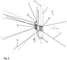
- the Fig. 2 shows the device with the sensor field generated by the radar sensors 2 1 - 2 n again under spatial representation of a portion of the in the Fig. 1 shown part of the drilling mast. 1
- the Fig. 3 illustrates the circumstances using a section of a plan view of the drilling mast 1. In both figures, the corresponding parts of the drilling mast 1 and the radar sensors 2 1 - 2 n are shown disregarding a uniform scale.
- the Fig. 4 shows an embodiment of the device according to the invention, in which either instead of or cumulatively to the radar sensors 2 1 - 2 n according to the FIGS. 1 to 3 provided radar sensors 3 1 - 3 n are arranged and aligned so that a sensor field is spanned by this, which is bordered by an imaginary, on the side opposite the bore side conically opening enveloping surface.
- By arranging, aligning and selecting the radar sensors 3 1 - 3 n with respect to the opening angle 10 (see Fig. 4 combined with Fig. 5 ) of the radiation emitted by them is achieved in that the main radiation lobes 8 of the radar emitting radar sensors 3 1 - 3 n sweep at any point parts of the drilling mast 1. Rather, the rays run in such a way that they are directed counter to the drilling direction b are and the longitudinal axis 5 of the drilling mast 1 or the imaginary extension of its outer peripheral surface intersect only above its axial end.
- radar sensors 3 1 - 3 n are preferably for use in the production of horizontal bores, for example in masonry, provided.
- the range of at the foot of the drilling mast 1 in the vicinity of the here shown, driven by boring bars or drill pipe boring head 12 radar sensors 3 1 - 3 n is in any case dimensioned so that the sensor field spanned by them over the entire axial length of the drilling mast 1 extends.
- the radiation profiles shown in the other figures here refer to the main beam lobe 8, make for each radar sensor 2 1 - 2 n ; 3 1 - 3 n in each case in area-projected representation of the two radiation main lobe 8 laterally enclosing radiation edges 11, 11 'of the radiation radar radiation is, where, as explained, a sweeping the drilling surface 4 and the drilling mast 1 by this radiation main lobe 8 by appropriate alignment of in the center running, dashed lines Radiation axis 6 is to be avoided.
- the angle enclosed by the radiation edges 11, 11 ' represents the opening angle 10.
- the representations and the explanations given there are based on a substantially symmetrical radiation image with a substantially symmetrical radiation main lobe 8 in whose center the radiation axis 6 extends.
- the figure shows a surface-projected representation of a radiation field. In fact, however, this naturally expands spatially, whereby in this respect too an essentially symmetrical field is assumed.
- the (imaginary) radiation edges 11, 11 'of the radiation field are in this case on the lateral surface of a (imaginary) truncated cone, the radiation axis 6 coincides with the central axis of this truncated cone.
Landscapes
- Engineering & Computer Science (AREA)
- Life Sciences & Earth Sciences (AREA)
- Geology (AREA)
- Mining & Mineral Resources (AREA)
- Physics & Mathematics (AREA)
- Environmental & Geological Engineering (AREA)
- Fluid Mechanics (AREA)
- General Life Sciences & Earth Sciences (AREA)
- Geochemistry & Mineralogy (AREA)
- Mechanical Engineering (AREA)
- Earth Drilling (AREA)
Priority Applications (1)
| Application Number | Priority Date | Filing Date | Title |
|---|---|---|---|
| PL17170407T PL3244004T3 (pl) | 2016-05-11 | 2017-05-10 | Zapewnienie bezpieczeństwa pracy na urządzeniach wiertniczych z masztem wiertniczym |
Applications Claiming Priority (2)
| Application Number | Priority Date | Filing Date | Title |
|---|---|---|---|
| DE202016102521.4U DE202016102521U1 (de) | 2016-05-11 | 2016-05-11 | Arbeitsschutzvorrichtung für Bohrgeräte mit Bohrmast |
| DE102016108709.2A DE102016108709A1 (de) | 2016-05-11 | 2016-05-11 | Gewährleistung des Arbeitsschutzes bei Bohrgeräten mit Bohrmast |
Publications (2)
| Publication Number | Publication Date |
|---|---|
| EP3244004A1 true EP3244004A1 (fr) | 2017-11-15 |
| EP3244004B1 EP3244004B1 (fr) | 2020-04-15 |
Family
ID=58699071
Family Applications (1)
| Application Number | Title | Priority Date | Filing Date |
|---|---|---|---|
| EP17170407.5A Active EP3244004B1 (fr) | 2016-05-11 | 2017-05-10 | Garantie de la protection des travailleurs utilisant des appareils de forage ayant un mât de forage |
Country Status (3)
| Country | Link |
|---|---|
| EP (1) | EP3244004B1 (fr) |
| ES (1) | ES2797917T3 (fr) |
| PL (1) | PL3244004T3 (fr) |
Citations (5)
| Publication number | Priority date | Publication date | Assignee | Title |
|---|---|---|---|---|
| DE3247202C1 (de) * | 1982-12-21 | 1984-06-14 | Ing. Günter Klemm, Spezialunternehmen für Bohrtechnik, 5962 Drolshagen | Bohrgerät |
| EP2048557A1 (fr) * | 2007-10-11 | 2009-04-15 | Sick Ag | Capteur optoélectronique et dispositif mobile ainsi que son procédé de configuration |
| GB2479749A (en) * | 2010-04-20 | 2011-10-26 | Cementation Skanska Ltd | Drill rig optical safety system |
| EP2952671A1 (fr) * | 2014-06-05 | 2015-12-09 | Soilmec S.p.A. | Système de sécurité pour équipement d'excavation |
| EP2957709A2 (fr) * | 2014-06-20 | 2015-12-23 | Soilmec S.p.A. | Système de sécurité permettant d'isoler les zones dangereuses d'une machine de forage, machine de forage pourvue d'un tel système de sécurité et procédé d'utilisation de ladite machine de forage |
-
2017
- 2017-05-10 ES ES17170407T patent/ES2797917T3/es active Active
- 2017-05-10 PL PL17170407T patent/PL3244004T3/pl unknown
- 2017-05-10 EP EP17170407.5A patent/EP3244004B1/fr active Active
Patent Citations (5)
| Publication number | Priority date | Publication date | Assignee | Title |
|---|---|---|---|---|
| DE3247202C1 (de) * | 1982-12-21 | 1984-06-14 | Ing. Günter Klemm, Spezialunternehmen für Bohrtechnik, 5962 Drolshagen | Bohrgerät |
| EP2048557A1 (fr) * | 2007-10-11 | 2009-04-15 | Sick Ag | Capteur optoélectronique et dispositif mobile ainsi que son procédé de configuration |
| GB2479749A (en) * | 2010-04-20 | 2011-10-26 | Cementation Skanska Ltd | Drill rig optical safety system |
| EP2952671A1 (fr) * | 2014-06-05 | 2015-12-09 | Soilmec S.p.A. | Système de sécurité pour équipement d'excavation |
| EP2957709A2 (fr) * | 2014-06-20 | 2015-12-23 | Soilmec S.p.A. | Système de sécurité permettant d'isoler les zones dangereuses d'une machine de forage, machine de forage pourvue d'un tel système de sécurité et procédé d'utilisation de ladite machine de forage |
Also Published As
| Publication number | Publication date |
|---|---|
| PL3244004T3 (pl) | 2020-09-21 |
| ES2797917T3 (es) | 2020-12-04 |
| EP3244004B1 (fr) | 2020-04-15 |
Similar Documents
| Publication | Publication Date | Title |
|---|---|---|
| DE10085344B4 (de) | Armierter Detektor | |
| DE102005015615A1 (de) | Verfahren und Vorrichtung zur Höhensteuerung | |
| DE102007025800A1 (de) | Gefahrenbereichsabsicherung für den Bereich der automatischen Rollenbestückung an einem Rollenwechsler | |
| EP2754343B1 (fr) | Dispositif de traitement de sol mobile avec dispositif de protection | |
| EP3521860B1 (fr) | Dispositif capteur optoélectronique | |
| DE202016102521U1 (de) | Arbeitsschutzvorrichtung für Bohrgeräte mit Bohrmast | |
| EP3244004B1 (fr) | Garantie de la protection des travailleurs utilisant des appareils de forage ayant un mât de forage | |
| EP3067511A1 (fr) | Appareil de forage vertical comprenant une zone de travail securisee | |
| DE102016108709A1 (de) | Gewährleistung des Arbeitsschutzes bei Bohrgeräten mit Bohrmast | |
| EP3553229B1 (fr) | Dispositif d'excavations et système de surveillance d'un chantier | |
| WO2021223903A1 (fr) | Dispositif et procédé de lutte sélective et mécanique contre les mauvaises herbes au moyen d'un mouvement d'évitement réversible d'unités actionneurs d'outil | |
| EP3239367B1 (fr) | Procédé de fonctionnement d'un brise-balles et brise-balles | |
| DE102011110848B4 (de) | Anschluss eines Sicherheitszaunfeldes und Sicherheitseinzäunung mit einem solchen Anschluss | |
| EP3165693B1 (fr) | Dispositif basculant destiné à assembler un mât et son emplanture | |
| DE19950849B4 (de) | Vorrichtung sowie Verfahren zur Detektion, Entfernungs-, Größen- und Temperaturmessung von einer Wärmequelle | |
| DE102016122650B4 (de) | Robotersicherheitssystem | |
| EP4402319B1 (fr) | Machine pour enfoncer un pieu de fondation | |
| DE102010006427A1 (de) | Einrichtung zum Abbau von Innenschornsteinen in Industrieschornsteinen und ähnlichen Bauwerken | |
| DE10227879A1 (de) | Lichtvorhang für bewegte Maschinen oder Maschinenteile | |
| DE102014004370B4 (de) | Vorrichtung zur Bearbeitung von Bodenflächen | |
| EP0533619B1 (fr) | Appareil de sécurité sur une pièce de machine mobile d'une machine textile | |
| EP4526584A1 (fr) | Système de surveillance | |
| DE102018126523B4 (de) | Arbeitsmaschine, insbesondere Radlader zum Holzumschlag | |
| CH685440A5 (de) | Sicherheitsvorrichtung an einem fahrbaren Maschinenteil einer Textilmaschine. | |
| DE9103089U1 (de) | Vorrichtung zum Auffinden und Zerstören von Minen |
Legal Events
| Date | Code | Title | Description |
|---|---|---|---|
| PUAI | Public reference made under article 153(3) epc to a published international application that has entered the european phase |
Free format text: ORIGINAL CODE: 0009012 |
|
| STAA | Information on the status of an ep patent application or granted ep patent |
Free format text: STATUS: THE APPLICATION HAS BEEN PUBLISHED |
|
| AK | Designated contracting states |
Kind code of ref document: A1 Designated state(s): AL AT BE BG CH CY CZ DE DK EE ES FI FR GB GR HR HU IE IS IT LI LT LU LV MC MK MT NL NO PL PT RO RS SE SI SK SM TR |
|
| AX | Request for extension of the european patent |
Extension state: BA ME |
|
| STAA | Information on the status of an ep patent application or granted ep patent |
Free format text: STATUS: REQUEST FOR EXAMINATION WAS MADE |
|
| 17P | Request for examination filed |
Effective date: 20180515 |
|
| RBV | Designated contracting states (corrected) |
Designated state(s): AL AT BE BG CH CY CZ DE DK EE ES FI FR GB GR HR HU IE IS IT LI LT LU LV MC MK MT NL NO PL PT RO RS SE SI SK SM TR |
|
| STAA | Information on the status of an ep patent application or granted ep patent |
Free format text: STATUS: EXAMINATION IS IN PROGRESS |
|
| 17Q | First examination report despatched |
Effective date: 20181022 |
|
| GRAP | Despatch of communication of intention to grant a patent |
Free format text: ORIGINAL CODE: EPIDOSNIGR1 |
|
| STAA | Information on the status of an ep patent application or granted ep patent |
Free format text: STATUS: GRANT OF PATENT IS INTENDED |
|
| INTG | Intention to grant announced |
Effective date: 20191106 |
|
| GRAS | Grant fee paid |
Free format text: ORIGINAL CODE: EPIDOSNIGR3 |
|
| GRAA | (expected) grant |
Free format text: ORIGINAL CODE: 0009210 |
|
| STAA | Information on the status of an ep patent application or granted ep patent |
Free format text: STATUS: THE PATENT HAS BEEN GRANTED |
|
| AK | Designated contracting states |
Kind code of ref document: B1 Designated state(s): AL AT BE BG CH CY CZ DE DK EE ES FI FR GB GR HR HU IE IS IT LI LT LU LV MC MK MT NL NO PL PT RO RS SE SI SK SM TR |
|
| REG | Reference to a national code |
Ref country code: CH Ref legal event code: EP |
|
| REG | Reference to a national code |
Ref country code: DE Ref legal event code: R096 Ref document number: 502017004709 Country of ref document: DE |
|
| REG | Reference to a national code |
Ref country code: IE Ref legal event code: FG4D Free format text: LANGUAGE OF EP DOCUMENT: GERMAN |
|
| REG | Reference to a national code |
Ref country code: AT Ref legal event code: REF Ref document number: 1257498 Country of ref document: AT Kind code of ref document: T Effective date: 20200515 |
|
| REG | Reference to a national code |
Ref country code: CH Ref legal event code: NV Representative=s name: R.A. EGLI AND CO, PATENTANWAELTE, CH |
|
| REG | Reference to a national code |
Ref country code: FI Ref legal event code: FGE |
|
| REG | Reference to a national code |
Ref country code: SE Ref legal event code: TRGR |
|
| REG | Reference to a national code |
Ref country code: NL Ref legal event code: MP Effective date: 20200415 |
|
| REG | Reference to a national code |
Ref country code: LT Ref legal event code: MG4D |
|
| PG25 | Lapsed in a contracting state [announced via postgrant information from national office to epo] |
Ref country code: NO Free format text: LAPSE BECAUSE OF FAILURE TO SUBMIT A TRANSLATION OF THE DESCRIPTION OR TO PAY THE FEE WITHIN THE PRESCRIBED TIME-LIMIT Effective date: 20200715 Ref country code: IS Free format text: LAPSE BECAUSE OF FAILURE TO SUBMIT A TRANSLATION OF THE DESCRIPTION OR TO PAY THE FEE WITHIN THE PRESCRIBED TIME-LIMIT Effective date: 20200815 Ref country code: NL Free format text: LAPSE BECAUSE OF FAILURE TO SUBMIT A TRANSLATION OF THE DESCRIPTION OR TO PAY THE FEE WITHIN THE PRESCRIBED TIME-LIMIT Effective date: 20200415 Ref country code: LT Free format text: LAPSE BECAUSE OF FAILURE TO SUBMIT A TRANSLATION OF THE DESCRIPTION OR TO PAY THE FEE WITHIN THE PRESCRIBED TIME-LIMIT Effective date: 20200415 Ref country code: PT Free format text: LAPSE BECAUSE OF FAILURE TO SUBMIT A TRANSLATION OF THE DESCRIPTION OR TO PAY THE FEE WITHIN THE PRESCRIBED TIME-LIMIT Effective date: 20200817 |
|
| PG25 | Lapsed in a contracting state [announced via postgrant information from national office to epo] |
Ref country code: RS Free format text: LAPSE BECAUSE OF FAILURE TO SUBMIT A TRANSLATION OF THE DESCRIPTION OR TO PAY THE FEE WITHIN THE PRESCRIBED TIME-LIMIT Effective date: 20200415 Ref country code: BG Free format text: LAPSE BECAUSE OF FAILURE TO SUBMIT A TRANSLATION OF THE DESCRIPTION OR TO PAY THE FEE WITHIN THE PRESCRIBED TIME-LIMIT Effective date: 20200715 Ref country code: HR Free format text: LAPSE BECAUSE OF FAILURE TO SUBMIT A TRANSLATION OF THE DESCRIPTION OR TO PAY THE FEE WITHIN THE PRESCRIBED TIME-LIMIT Effective date: 20200415 Ref country code: LV Free format text: LAPSE BECAUSE OF FAILURE TO SUBMIT A TRANSLATION OF THE DESCRIPTION OR TO PAY THE FEE WITHIN THE PRESCRIBED TIME-LIMIT Effective date: 20200415 |
|
| REG | Reference to a national code |
Ref country code: ES Ref legal event code: FG2A Ref document number: 2797917 Country of ref document: ES Kind code of ref document: T3 Effective date: 20201204 |
|
| PG25 | Lapsed in a contracting state [announced via postgrant information from national office to epo] |
Ref country code: AL Free format text: LAPSE BECAUSE OF FAILURE TO SUBMIT A TRANSLATION OF THE DESCRIPTION OR TO PAY THE FEE WITHIN THE PRESCRIBED TIME-LIMIT Effective date: 20200415 |
|
| REG | Reference to a national code |
Ref country code: DE Ref legal event code: R097 Ref document number: 502017004709 Country of ref document: DE |
|
| PG25 | Lapsed in a contracting state [announced via postgrant information from national office to epo] |
Ref country code: MC Free format text: LAPSE BECAUSE OF FAILURE TO SUBMIT A TRANSLATION OF THE DESCRIPTION OR TO PAY THE FEE WITHIN THE PRESCRIBED TIME-LIMIT Effective date: 20200415 Ref country code: DK Free format text: LAPSE BECAUSE OF FAILURE TO SUBMIT A TRANSLATION OF THE DESCRIPTION OR TO PAY THE FEE WITHIN THE PRESCRIBED TIME-LIMIT Effective date: 20200415 Ref country code: SM Free format text: LAPSE BECAUSE OF FAILURE TO SUBMIT A TRANSLATION OF THE DESCRIPTION OR TO PAY THE FEE WITHIN THE PRESCRIBED TIME-LIMIT Effective date: 20200415 Ref country code: EE Free format text: LAPSE BECAUSE OF FAILURE TO SUBMIT A TRANSLATION OF THE DESCRIPTION OR TO PAY THE FEE WITHIN THE PRESCRIBED TIME-LIMIT Effective date: 20200415 Ref country code: CZ Free format text: LAPSE BECAUSE OF FAILURE TO SUBMIT A TRANSLATION OF THE DESCRIPTION OR TO PAY THE FEE WITHIN THE PRESCRIBED TIME-LIMIT Effective date: 20200415 Ref country code: RO Free format text: LAPSE BECAUSE OF FAILURE TO SUBMIT A TRANSLATION OF THE DESCRIPTION OR TO PAY THE FEE WITHIN THE PRESCRIBED TIME-LIMIT Effective date: 20200415 |
|
| PLBE | No opposition filed within time limit |
Free format text: ORIGINAL CODE: 0009261 |
|
| STAA | Information on the status of an ep patent application or granted ep patent |
Free format text: STATUS: NO OPPOSITION FILED WITHIN TIME LIMIT |
|
| PG25 | Lapsed in a contracting state [announced via postgrant information from national office to epo] |
Ref country code: SK Free format text: LAPSE BECAUSE OF FAILURE TO SUBMIT A TRANSLATION OF THE DESCRIPTION OR TO PAY THE FEE WITHIN THE PRESCRIBED TIME-LIMIT Effective date: 20200415 |
|
| 26N | No opposition filed |
Effective date: 20210118 |
|
| PG25 | Lapsed in a contracting state [announced via postgrant information from national office to epo] |
Ref country code: LU Free format text: LAPSE BECAUSE OF NON-PAYMENT OF DUE FEES Effective date: 20200510 |
|
| PG25 | Lapsed in a contracting state [announced via postgrant information from national office to epo] |
Ref country code: SI Free format text: LAPSE BECAUSE OF FAILURE TO SUBMIT A TRANSLATION OF THE DESCRIPTION OR TO PAY THE FEE WITHIN THE PRESCRIBED TIME-LIMIT Effective date: 20200415 |
|
| PG25 | Lapsed in a contracting state [announced via postgrant information from national office to epo] |
Ref country code: TR Free format text: LAPSE BECAUSE OF FAILURE TO SUBMIT A TRANSLATION OF THE DESCRIPTION OR TO PAY THE FEE WITHIN THE PRESCRIBED TIME-LIMIT Effective date: 20200415 Ref country code: MT Free format text: LAPSE BECAUSE OF FAILURE TO SUBMIT A TRANSLATION OF THE DESCRIPTION OR TO PAY THE FEE WITHIN THE PRESCRIBED TIME-LIMIT Effective date: 20200415 Ref country code: CY Free format text: LAPSE BECAUSE OF FAILURE TO SUBMIT A TRANSLATION OF THE DESCRIPTION OR TO PAY THE FEE WITHIN THE PRESCRIBED TIME-LIMIT Effective date: 20200415 |
|
| PG25 | Lapsed in a contracting state [announced via postgrant information from national office to epo] |
Ref country code: MK Free format text: LAPSE BECAUSE OF FAILURE TO SUBMIT A TRANSLATION OF THE DESCRIPTION OR TO PAY THE FEE WITHIN THE PRESCRIBED TIME-LIMIT Effective date: 20200415 |
|
| PG25 | Lapsed in a contracting state [announced via postgrant information from national office to epo] |
Ref country code: GR Free format text: LAPSE BECAUSE OF FAILURE TO SUBMIT A TRANSLATION OF THE DESCRIPTION OR TO PAY THE FEE WITHIN THE PRESCRIBED TIME-LIMIT Effective date: 20200415 |
|
| REG | Reference to a national code |
Ref country code: DE Ref legal event code: R082 Ref document number: 502017004709 Country of ref document: DE Representative=s name: MAUCHER JENKINS PATENTANWAELTE & RECHTSANWAELT, DE |
|
| PGFP | Annual fee paid to national office [announced via postgrant information from national office to epo] |
Ref country code: FI Payment date: 20250520 Year of fee payment: 9 |
|
| PGFP | Annual fee paid to national office [announced via postgrant information from national office to epo] |
Ref country code: DE Payment date: 20250513 Year of fee payment: 9 Ref country code: PL Payment date: 20250505 Year of fee payment: 9 |
|
| PGFP | Annual fee paid to national office [announced via postgrant information from national office to epo] |
Ref country code: ES Payment date: 20250616 Year of fee payment: 9 |
|
| PGFP | Annual fee paid to national office [announced via postgrant information from national office to epo] |
Ref country code: IT Payment date: 20250530 Year of fee payment: 9 Ref country code: BE Payment date: 20250520 Year of fee payment: 9 |
|
| PGFP | Annual fee paid to national office [announced via postgrant information from national office to epo] |
Ref country code: FR Payment date: 20250521 Year of fee payment: 9 |
|
| PGFP | Annual fee paid to national office [announced via postgrant information from national office to epo] |
Ref country code: CH Payment date: 20250601 Year of fee payment: 9 |
|
| PGFP | Annual fee paid to national office [announced via postgrant information from national office to epo] |
Ref country code: AT Payment date: 20250519 Year of fee payment: 9 |
|
| PGFP | Annual fee paid to national office [announced via postgrant information from national office to epo] |
Ref country code: IE Payment date: 20250522 Year of fee payment: 9 |
|
| PGFP | Annual fee paid to national office [announced via postgrant information from national office to epo] |
Ref country code: SE Payment date: 20250522 Year of fee payment: 9 |
|
| PGFP | Annual fee paid to national office [announced via postgrant information from national office to epo] |
Ref country code: GB Payment date: 20260324 Year of fee payment: 10 |