EP2958723B1 - Granulateur à cylindres broyeurs et son utilisation - Google Patents
Granulateur à cylindres broyeurs et son utilisation Download PDFInfo
- Publication number
- EP2958723B1 EP2958723B1 EP14706781.3A EP14706781A EP2958723B1 EP 2958723 B1 EP2958723 B1 EP 2958723B1 EP 14706781 A EP14706781 A EP 14706781A EP 2958723 B1 EP2958723 B1 EP 2958723B1
- Authority
- EP
- European Patent Office
- Prior art keywords
- squeezing
- zone
- roller
- tooth
- squeeze roller
- Prior art date
- Legal status (The legal status is an assumption and is not a legal conclusion. Google has not performed a legal analysis and makes no representation as to the accuracy of the status listed.)
- Active
Links
Images


Classifications
-
- B—PERFORMING OPERATIONS; TRANSPORTING
- B29—WORKING OF PLASTICS; WORKING OF SUBSTANCES IN A PLASTIC STATE IN GENERAL
- B29B—PREPARATION OR PRETREATMENT OF THE MATERIAL TO BE SHAPED; MAKING GRANULES OR PREFORMS; RECOVERY OF PLASTICS OR OTHER CONSTITUENTS OF WASTE MATERIAL CONTAINING PLASTICS
- B29B9/00—Making granules
- B29B9/02—Making granules by dividing preformed material
- B29B9/06—Making granules by dividing preformed material in the form of filamentary material, e.g. combined with extrusion
-
- B—PERFORMING OPERATIONS; TRANSPORTING
- B01—PHYSICAL OR CHEMICAL PROCESSES OR APPARATUS IN GENERAL
- B01J—CHEMICAL OR PHYSICAL PROCESSES, e.g. CATALYSIS OR COLLOID CHEMISTRY; THEIR RELEVANT APPARATUS
- B01J2/00—Processes or devices for granulating materials, e.g. fertilisers in general; Rendering particulate materials free flowing in general, e.g. making them hydrophobic
- B01J2/22—Processes or devices for granulating materials, e.g. fertilisers in general; Rendering particulate materials free flowing in general, e.g. making them hydrophobic by pressing in moulds or between rollers
-
- B—PERFORMING OPERATIONS; TRANSPORTING
- B29—WORKING OF PLASTICS; WORKING OF SUBSTANCES IN A PLASTIC STATE IN GENERAL
- B29B—PREPARATION OR PRETREATMENT OF THE MATERIAL TO BE SHAPED; MAKING GRANULES OR PREFORMS; RECOVERY OF PLASTICS OR OTHER CONSTITUENTS OF WASTE MATERIAL CONTAINING PLASTICS
- B29B9/00—Making granules
- B29B9/12—Making granules characterised by structure or composition
-
- B—PERFORMING OPERATIONS; TRANSPORTING
- B29—WORKING OF PLASTICS; WORKING OF SUBSTANCES IN A PLASTIC STATE IN GENERAL
- B29C—SHAPING OR JOINING OF PLASTICS; SHAPING OF MATERIAL IN A PLASTIC STATE, NOT OTHERWISE PROVIDED FOR; AFTER-TREATMENT OF THE SHAPED PRODUCTS, e.g. REPAIRING
- B29C48/00—Extrusion moulding, i.e. expressing the moulding material through a die or nozzle which imparts the desired form; Apparatus therefor
- B29C48/001—Combinations of extrusion moulding with other shaping operations
- B29C48/0011—Combinations of extrusion moulding with other shaping operations combined with compression moulding
-
- B—PERFORMING OPERATIONS; TRANSPORTING
- B29—WORKING OF PLASTICS; WORKING OF SUBSTANCES IN A PLASTIC STATE IN GENERAL
- B29C—SHAPING OR JOINING OF PLASTICS; SHAPING OF MATERIAL IN A PLASTIC STATE, NOT OTHERWISE PROVIDED FOR; AFTER-TREATMENT OF THE SHAPED PRODUCTS, e.g. REPAIRING
- B29C48/00—Extrusion moulding, i.e. expressing the moulding material through a die or nozzle which imparts the desired form; Apparatus therefor
- B29C48/001—Combinations of extrusion moulding with other shaping operations
- B29C48/0022—Combinations of extrusion moulding with other shaping operations combined with cutting
-
- B—PERFORMING OPERATIONS; TRANSPORTING
- B29—WORKING OF PLASTICS; WORKING OF SUBSTANCES IN A PLASTIC STATE IN GENERAL
- B29C—SHAPING OR JOINING OF PLASTICS; SHAPING OF MATERIAL IN A PLASTIC STATE, NOT OTHERWISE PROVIDED FOR; AFTER-TREATMENT OF THE SHAPED PRODUCTS, e.g. REPAIRING
- B29C48/00—Extrusion moulding, i.e. expressing the moulding material through a die or nozzle which imparts the desired form; Apparatus therefor
- B29C48/03—Extrusion moulding, i.e. expressing the moulding material through a die or nozzle which imparts the desired form; Apparatus therefor characterised by the shape of the extruded material at extrusion
- B29C48/04—Particle-shaped
-
- B—PERFORMING OPERATIONS; TRANSPORTING
- B29—WORKING OF PLASTICS; WORKING OF SUBSTANCES IN A PLASTIC STATE IN GENERAL
- B29C—SHAPING OR JOINING OF PLASTICS; SHAPING OF MATERIAL IN A PLASTIC STATE, NOT OTHERWISE PROVIDED FOR; AFTER-TREATMENT OF THE SHAPED PRODUCTS, e.g. REPAIRING
- B29C48/00—Extrusion moulding, i.e. expressing the moulding material through a die or nozzle which imparts the desired form; Apparatus therefor
- B29C48/03—Extrusion moulding, i.e. expressing the moulding material through a die or nozzle which imparts the desired form; Apparatus therefor characterised by the shape of the extruded material at extrusion
- B29C48/05—Filamentary, e.g. strands
-
- B—PERFORMING OPERATIONS; TRANSPORTING
- B29—WORKING OF PLASTICS; WORKING OF SUBSTANCES IN A PLASTIC STATE IN GENERAL
- B29C—SHAPING OR JOINING OF PLASTICS; SHAPING OF MATERIAL IN A PLASTIC STATE, NOT OTHERWISE PROVIDED FOR; AFTER-TREATMENT OF THE SHAPED PRODUCTS, e.g. REPAIRING
- B29C48/00—Extrusion moulding, i.e. expressing the moulding material through a die or nozzle which imparts the desired form; Apparatus therefor
- B29C48/03—Extrusion moulding, i.e. expressing the moulding material through a die or nozzle which imparts the desired form; Apparatus therefor characterised by the shape of the extruded material at extrusion
- B29C48/09—Articles with cross-sections having partially or fully enclosed cavities, e.g. pipes or channels
-
- B—PERFORMING OPERATIONS; TRANSPORTING
- B29—WORKING OF PLASTICS; WORKING OF SUBSTANCES IN A PLASTIC STATE IN GENERAL
- B29C—SHAPING OR JOINING OF PLASTICS; SHAPING OF MATERIAL IN A PLASTIC STATE, NOT OTHERWISE PROVIDED FOR; AFTER-TREATMENT OF THE SHAPED PRODUCTS, e.g. REPAIRING
- B29C48/00—Extrusion moulding, i.e. expressing the moulding material through a die or nozzle which imparts the desired form; Apparatus therefor
- B29C48/25—Component parts, details or accessories; Auxiliary operations
- B29C48/88—Thermal treatment of the stream of extruded material, e.g. cooling
- B29C48/919—Thermal treatment of the stream of extruded material, e.g. cooling using a bath, e.g. extruding into an open bath to coagulate or cool the material
-
- B—PERFORMING OPERATIONS; TRANSPORTING
- B29—WORKING OF PLASTICS; WORKING OF SUBSTANCES IN A PLASTIC STATE IN GENERAL
- B29C—SHAPING OR JOINING OF PLASTICS; SHAPING OF MATERIAL IN A PLASTIC STATE, NOT OTHERWISE PROVIDED FOR; AFTER-TREATMENT OF THE SHAPED PRODUCTS, e.g. REPAIRING
- B29C48/00—Extrusion moulding, i.e. expressing the moulding material through a die or nozzle which imparts the desired form; Apparatus therefor
- B29C48/25—Component parts, details or accessories; Auxiliary operations
- B29C48/92—Measuring, controlling or regulating
-
- B—PERFORMING OPERATIONS; TRANSPORTING
- B29—WORKING OF PLASTICS; WORKING OF SUBSTANCES IN A PLASTIC STATE IN GENERAL
- B29B—PREPARATION OR PRETREATMENT OF THE MATERIAL TO BE SHAPED; MAKING GRANULES OR PREFORMS; RECOVERY OF PLASTICS OR OTHER CONSTITUENTS OF WASTE MATERIAL CONTAINING PLASTICS
- B29B9/00—Making granules
- B29B9/16—Auxiliary treatment of granules
- B29B2009/168—Removing undesirable residual components, e.g. solvents, unreacted monomers; Degassing
-
- B—PERFORMING OPERATIONS; TRANSPORTING
- B29—WORKING OF PLASTICS; WORKING OF SUBSTANCES IN A PLASTIC STATE IN GENERAL
- B29B—PREPARATION OR PRETREATMENT OF THE MATERIAL TO BE SHAPED; MAKING GRANULES OR PREFORMS; RECOVERY OF PLASTICS OR OTHER CONSTITUENTS OF WASTE MATERIAL CONTAINING PLASTICS
- B29B9/00—Making granules
- B29B9/08—Making granules by agglomerating smaller particles
-
- B—PERFORMING OPERATIONS; TRANSPORTING
- B29—WORKING OF PLASTICS; WORKING OF SUBSTANCES IN A PLASTIC STATE IN GENERAL
- B29C—SHAPING OR JOINING OF PLASTICS; SHAPING OF MATERIAL IN A PLASTIC STATE, NOT OTHERWISE PROVIDED FOR; AFTER-TREATMENT OF THE SHAPED PRODUCTS, e.g. REPAIRING
- B29C2793/00—Shaping techniques involving a cutting or machining operation
- B29C2793/0027—Cutting off
-
- B—PERFORMING OPERATIONS; TRANSPORTING
- B29—WORKING OF PLASTICS; WORKING OF SUBSTANCES IN A PLASTIC STATE IN GENERAL
- B29C—SHAPING OR JOINING OF PLASTICS; SHAPING OF MATERIAL IN A PLASTIC STATE, NOT OTHERWISE PROVIDED FOR; AFTER-TREATMENT OF THE SHAPED PRODUCTS, e.g. REPAIRING
- B29C2793/00—Shaping techniques involving a cutting or machining operation
- B29C2793/0054—Shaping techniques involving a cutting or machining operation partially cutting through the material
-
- B—PERFORMING OPERATIONS; TRANSPORTING
- B29—WORKING OF PLASTICS; WORKING OF SUBSTANCES IN A PLASTIC STATE IN GENERAL
- B29C—SHAPING OR JOINING OF PLASTICS; SHAPING OF MATERIAL IN A PLASTIC STATE, NOT OTHERWISE PROVIDED FOR; AFTER-TREATMENT OF THE SHAPED PRODUCTS, e.g. REPAIRING
- B29C2948/00—Indexing scheme relating to extrusion moulding
- B29C2948/92—Measuring, controlling or regulating
- B29C2948/92009—Measured parameter
- B29C2948/92209—Temperature
-
- B—PERFORMING OPERATIONS; TRANSPORTING
- B29—WORKING OF PLASTICS; WORKING OF SUBSTANCES IN A PLASTIC STATE IN GENERAL
- B29C—SHAPING OR JOINING OF PLASTICS; SHAPING OF MATERIAL IN A PLASTIC STATE, NOT OTHERWISE PROVIDED FOR; AFTER-TREATMENT OF THE SHAPED PRODUCTS, e.g. REPAIRING
- B29C2948/00—Indexing scheme relating to extrusion moulding
- B29C2948/92—Measuring, controlling or regulating
- B29C2948/92323—Location or phase of measurement
- B29C2948/92428—Calibration, after-treatment, or cooling zone
-
- B—PERFORMING OPERATIONS; TRANSPORTING
- B29—WORKING OF PLASTICS; WORKING OF SUBSTANCES IN A PLASTIC STATE IN GENERAL
- B29C—SHAPING OR JOINING OF PLASTICS; SHAPING OF MATERIAL IN A PLASTIC STATE, NOT OTHERWISE PROVIDED FOR; AFTER-TREATMENT OF THE SHAPED PRODUCTS, e.g. REPAIRING
- B29C2948/00—Indexing scheme relating to extrusion moulding
- B29C2948/92—Measuring, controlling or regulating
- B29C2948/92323—Location or phase of measurement
- B29C2948/92476—Fluids, e.g. for temperature control or of environment
-
- B—PERFORMING OPERATIONS; TRANSPORTING
- B29—WORKING OF PLASTICS; WORKING OF SUBSTANCES IN A PLASTIC STATE IN GENERAL
- B29C—SHAPING OR JOINING OF PLASTICS; SHAPING OF MATERIAL IN A PLASTIC STATE, NOT OTHERWISE PROVIDED FOR; AFTER-TREATMENT OF THE SHAPED PRODUCTS, e.g. REPAIRING
- B29C2948/00—Indexing scheme relating to extrusion moulding
- B29C2948/92—Measuring, controlling or regulating
- B29C2948/92504—Controlled parameter
- B29C2948/9258—Velocity
- B29C2948/9259—Angular velocity
-
- B—PERFORMING OPERATIONS; TRANSPORTING
- B29—WORKING OF PLASTICS; WORKING OF SUBSTANCES IN A PLASTIC STATE IN GENERAL
- B29C—SHAPING OR JOINING OF PLASTICS; SHAPING OF MATERIAL IN A PLASTIC STATE, NOT OTHERWISE PROVIDED FOR; AFTER-TREATMENT OF THE SHAPED PRODUCTS, e.g. REPAIRING
- B29C2948/00—Indexing scheme relating to extrusion moulding
- B29C2948/92—Measuring, controlling or regulating
- B29C2948/92504—Controlled parameter
- B29C2948/9258—Velocity
- B29C2948/926—Flow or feed rate
-
- B—PERFORMING OPERATIONS; TRANSPORTING
- B29—WORKING OF PLASTICS; WORKING OF SUBSTANCES IN A PLASTIC STATE IN GENERAL
- B29C—SHAPING OR JOINING OF PLASTICS; SHAPING OF MATERIAL IN A PLASTIC STATE, NOT OTHERWISE PROVIDED FOR; AFTER-TREATMENT OF THE SHAPED PRODUCTS, e.g. REPAIRING
- B29C2948/00—Indexing scheme relating to extrusion moulding
- B29C2948/92—Measuring, controlling or regulating
- B29C2948/92504—Controlled parameter
- B29C2948/92704—Temperature
-
- B—PERFORMING OPERATIONS; TRANSPORTING
- B29—WORKING OF PLASTICS; WORKING OF SUBSTANCES IN A PLASTIC STATE IN GENERAL
- B29C—SHAPING OR JOINING OF PLASTICS; SHAPING OF MATERIAL IN A PLASTIC STATE, NOT OTHERWISE PROVIDED FOR; AFTER-TREATMENT OF THE SHAPED PRODUCTS, e.g. REPAIRING
- B29C2948/00—Indexing scheme relating to extrusion moulding
- B29C2948/92—Measuring, controlling or regulating
- B29C2948/92819—Location or phase of control
- B29C2948/92857—Extrusion unit
- B29C2948/92876—Feeding, melting, plasticising or pumping zones, e.g. the melt itself
-
- B—PERFORMING OPERATIONS; TRANSPORTING
- B29—WORKING OF PLASTICS; WORKING OF SUBSTANCES IN A PLASTIC STATE IN GENERAL
- B29C—SHAPING OR JOINING OF PLASTICS; SHAPING OF MATERIAL IN A PLASTIC STATE, NOT OTHERWISE PROVIDED FOR; AFTER-TREATMENT OF THE SHAPED PRODUCTS, e.g. REPAIRING
- B29C2948/00—Indexing scheme relating to extrusion moulding
- B29C2948/92—Measuring, controlling or regulating
- B29C2948/92819—Location or phase of control
- B29C2948/92923—Calibration, after-treatment or cooling zone
-
- B—PERFORMING OPERATIONS; TRANSPORTING
- B29—WORKING OF PLASTICS; WORKING OF SUBSTANCES IN A PLASTIC STATE IN GENERAL
- B29C—SHAPING OR JOINING OF PLASTICS; SHAPING OF MATERIAL IN A PLASTIC STATE, NOT OTHERWISE PROVIDED FOR; AFTER-TREATMENT OF THE SHAPED PRODUCTS, e.g. REPAIRING
- B29C2948/00—Indexing scheme relating to extrusion moulding
- B29C2948/92—Measuring, controlling or regulating
- B29C2948/92819—Location or phase of control
- B29C2948/92933—Conveying, transporting or storage of articles
-
- B—PERFORMING OPERATIONS; TRANSPORTING
- B29—WORKING OF PLASTICS; WORKING OF SUBSTANCES IN A PLASTIC STATE IN GENERAL
- B29C—SHAPING OR JOINING OF PLASTICS; SHAPING OF MATERIAL IN A PLASTIC STATE, NOT OTHERWISE PROVIDED FOR; AFTER-TREATMENT OF THE SHAPED PRODUCTS, e.g. REPAIRING
- B29C2948/00—Indexing scheme relating to extrusion moulding
- B29C2948/92—Measuring, controlling or regulating
- B29C2948/92819—Location or phase of control
- B29C2948/92971—Fluids, e.g. for temperature control or of environment
-
- B—PERFORMING OPERATIONS; TRANSPORTING
- B29—WORKING OF PLASTICS; WORKING OF SUBSTANCES IN A PLASTIC STATE IN GENERAL
- B29C—SHAPING OR JOINING OF PLASTICS; SHAPING OF MATERIAL IN A PLASTIC STATE, NOT OTHERWISE PROVIDED FOR; AFTER-TREATMENT OF THE SHAPED PRODUCTS, e.g. REPAIRING
- B29C48/00—Extrusion moulding, i.e. expressing the moulding material through a die or nozzle which imparts the desired form; Apparatus therefor
- B29C48/16—Articles comprising two or more components, e.g. co-extruded layers
- B29C48/18—Articles comprising two or more components, e.g. co-extruded layers the components being layers
- B29C48/21—Articles comprising two or more components, e.g. co-extruded layers the components being layers the layers being joined at their surfaces
-
- B—PERFORMING OPERATIONS; TRANSPORTING
- B29—WORKING OF PLASTICS; WORKING OF SUBSTANCES IN A PLASTIC STATE IN GENERAL
- B29C—SHAPING OR JOINING OF PLASTICS; SHAPING OF MATERIAL IN A PLASTIC STATE, NOT OTHERWISE PROVIDED FOR; AFTER-TREATMENT OF THE SHAPED PRODUCTS, e.g. REPAIRING
- B29C48/00—Extrusion moulding, i.e. expressing the moulding material through a die or nozzle which imparts the desired form; Apparatus therefor
- B29C48/25—Component parts, details or accessories; Auxiliary operations
- B29C48/30—Extrusion nozzles or dies
- B29C48/32—Extrusion nozzles or dies with annular openings, e.g. for forming tubular articles
- B29C48/335—Multiple annular extrusion nozzles in coaxial arrangement, e.g. for making multi-layered tubular articles
-
- B—PERFORMING OPERATIONS; TRANSPORTING
- B29—WORKING OF PLASTICS; WORKING OF SUBSTANCES IN A PLASTIC STATE IN GENERAL
- B29K—INDEXING SCHEME ASSOCIATED WITH SUBCLASSES B29B, B29C OR B29D, RELATING TO MOULDING MATERIALS OR TO MATERIALS FOR MOULDS, REINFORCEMENTS, FILLERS OR PREFORMED PARTS, e.g. INSERTS
- B29K2091/00—Use of waxes as moulding material
-
- B—PERFORMING OPERATIONS; TRANSPORTING
- B29—WORKING OF PLASTICS; WORKING OF SUBSTANCES IN A PLASTIC STATE IN GENERAL
- B29K—INDEXING SCHEME ASSOCIATED WITH SUBCLASSES B29B, B29C OR B29D, RELATING TO MOULDING MATERIALS OR TO MATERIALS FOR MOULDS, REINFORCEMENTS, FILLERS OR PREFORMED PARTS, e.g. INSERTS
- B29K2101/00—Use of unspecified macromolecular compounds as moulding material
- B29K2101/12—Thermoplastic materials
Definitions
- the invention relates to a squeeze roller granulator having a cylindrical pressure roller and a toothed nip roll, wherein the teeth of the nip roll tooth flanks disposed between a Zahnfuß Scheme and a tooth tip region, and wherein the Zahnfuß Scheme has an outer diameter which is smaller than the outer diameter of the tooth tip region.
- a squeeze roller granulator for granulating strands of plastic material and similar plastic masses is known from the document DE 31 45 614 C2 known, wherein the strands of plastic material and similar plastic masses are hereinafter referred to as plastic strands, in particular if they have an enveloping tube with enclosed filling material.
- the known squeezing roller device has a feeding device for at least one externally solidified strand, which leads to a roller pair driven in opposite directions about parallel axes.
- At least one roller of the roller pair is made of hard material with respect to the plastic material and has substantially axially extending circumferentially distributed projections. Radially outer ends of the nip roll cooperate with a smooth cylindrical surface of the nip roll. Here, the radially outer surface areas of the projections on the pressure roller approximately come to rest, so that the roller is held in this position under bias in a stop and the plastic material of the plastic strand is divided into granules.
- a disadvantage of this device is that it is not able to produce granulated sachets with a filling mass, as they are needed in multiple variations for different applications. For this need are from the pamphlets DE 103 47 908 A1 . DE 38 32 566 C2 and from the layout DE 1 297 525 A Methods and apparatus using a coextrusion process to extrude a multilayer plastic container from tubular coextruded To produce plastic materials, which is formed into containers, wherein a Browndorn allows after coextruding the container to introduce a filling material in the coextruded and molded container.
- German Auslegeschrift DE 26 27 263 B1 describes a device for cooling and granulating strands of thermoplastic materials, which has as part of a pair of feed rollers a grooved feed roller.
- EP 1 066 938 A1 describes a device for granulating plastic strands, which also has as part of a pair of feed rollers a grooved feed roller.
- the Japanese script JP S59 081120 A shows squeezing rollers with rounded transitions between respective tooth root, tooth flank and tooth tip regions.
- the European patent application EP 0 143 414 A2 shows a toothed press roller with rounded transitions between respective tooth root, tooth flank and tooth tip regions.
- An embodiment of the nip roller granulator according to the invention has a cylindrical pressure roller and a toothed nip roll, wherein the toothing of the nip roller tooth flanks, which between a Zahnfuß Scheme and a tooth tip portion, and wherein the tooth root portion has an outer diameter smaller than the outer diameter of the tooth tip portion, and wherein the tooth tip portion of the pinch roller has three pinch zones with a center pinch zone defining different distances to the cylindrical pinch roller with a minimum gap in the range the center crimping zone, and wherein the contour of the tooth flanks and the Zahnfuß Schemes the nip roller in cooperation with the contour of the cylindrical pressure roller defines a maximum cross section of granules to be formed, and wherein the maximum filling volume additionally depends on the width to which the granule pad is squeezed.
- the advantage of the squeeze roller granulator according to the invention is that it can portioned with a single squeegee rotation a variety of fillers in granules cushion and media density, which is not possible with the previously known squeeze roller granulator, which separates only pre-solidified strands to plastic granules. Also known from the above-cited documents devices for coextruding multi-layer containers with filling the container via a Gredom and then closing the container are not able to allow mass production of precisely portioned fillers in an outer shell media-tight.
- the root portion extends from an end of a trailing tooth flank to a beginning of a rising flank
- the tip portion extends correspondingly from an end of a rising flank to a beginning of a trailing flank.
- the three pinch zones of the tooth tip region have an input crimping zone arranged in a feed direction, an exit crimping zone arranged in a discharge direction, and the center crimping zone arranged between the input and output crimping zones.
- the input and output crimping zones of the toothing are limited by the tooth flanks.
- the entrance crush zone defines a distance from the nip roll that decreases toward the center nip
- the exit nip defines a distance from the nip roll that increases from the center nip. with a rise angle ⁇ e for the input crush zone between 2 ° and 8 ° and a drop angle ⁇ a for the output crush zone between 2 ° and 8 °.
- this has the advantage that the filling compound in the successive rolling surfaces of the pressure roller and the pinch zones of the tooth tip areas of the nip roller, the filling masses of a supplied, filled with filling sheath sleeve can be displaced such that in the thoroughlysquetschzone a media-tight welding of the shell material to a varietiessdichtnaht occurs and the same occurs in yogaquetschzonen the Zahnkopf Suite in which media density administratdichtnähte be formed.
- a predetermined breaking seam profile in which adjoining granular cushion can be separated from each other.
- the squeeze roller granulator has a supply device for supplying an enveloping tube with coextruded filling compound.
- a supply device for supplying an enveloping tube with coextruded filling compound.
- the squeeze roller granulator according to the invention consequently not only a multi-layered outer shell can be achieved by coextrusion of shell materials, but especially for a preferably single-layered sleeve, with which a filler is co-extruded, in the pair of rollers pressure roller and squeegee with the special design of the tooth tip region provided in three squeeze a device that can fill granules cushion and simultaneously seal media-tight.
- the granules cushion portions of the filling compound which are enveloped by an outer shell of the material of the buffer tube.
- An advantage of such a squeeze roller granulator with an extruded buffer tube and the coextruded filling compound enclosed in the buffer tube achieves a mass throughput and output of granules which can not be achieved with conventional systems for producing and filling containers.
- the region of the tooth tip has a chamfered input edge to the input crimping zone and a chamfered output edge from the output crimping zone.
- the center crushing zone of the tooth tip region of the nip roll has a flattening as predetermined fracture seam profile.
- This flattening which has a minimum distance to the cylinder surface of the pressure roller, allows a predetermined breaking seam of minimum thickness between two adjacent granular cushion.
- the center pinch zone of the tooth tip region of the nip roll has a step as a predetermined breaking seam profile.
- a step with a minimal distance to the cylinder surface of the pressure roller acts like a cutting edge, so that at minimum load this predetermined breaking seam is suitable for separating adjacent granular cushion.
- the center crushing zone of the tooth tip region of the nip roll has a web cross section projecting beyond the entry crush zone and the exit crush zone.
- Such a web cross-section additionally reduces the distance between the cylinder surface of the pressure roller, so that even in this embodiment, the center pinch zone can act as a separating knife, which enables separation of the granules even at low load of the resulting predetermined breaking seam.
- the qualifyingquetschzone is longer than the possible sizes of the devices. This results in the advantage that the touchscreentschnaht is wider or longer than the possiblesquetschnaht, so that the risk of damage to the Ninthnaht when separating a granular pad from a subsequent granules cushion is still significantly reduced during the crimping of the nip.
- the squeezing roller and the pressure roller have a metal alloy, wherein the cylindrical surface of the pressure roller and the tooth tip areas of the squeegee wear-resistant surfaces, preferably surfaces of hard metal coatings or ceramic coatings or hardened surfaces.
- a hardening of the surfaces or the Tooth region of the nip roll is preferably achieved by means of an inductive hardening process in which the surfaces of the tooth tip regions can be inductively heated and subsequently cooled.
- it is also possible to achieve an improved hardness by providing hard metal coatings or ceramic coatings such as nitride or carbide layers on the surfaces. The harder the surfaces are formed, the more precisely the defined different distances between the three pinch zones can form between the granulate pads.
- PA group polyamide
- PP polypropylene
- LDPE low density polyethylene
- COP copolymer
- EVOH ethylene-vinyl alcohol copolymer
- EVA ethylene-vinyl acetate copolymer
- the squeezing roller can constantly be in a minimum distance from the cylindrical surface of the pressure roller at least with a partial region of a center crimping zone of the gearing. Therefore, it is provided to provide the nip roll with a helical toothing, wherein the helical angle or angle ⁇ depends on the outer diameter D of the nip roll and the width B of the nip roll and the number n of distributed on the outer circumference teeth of the nip roll.
- nip roll From the requirement to ensure a two-point support between the outer teeth of the nip roll and the cylindrical surface of the pressure roller, at least a portion of the nip roll must be arranged at a minimum distance from the cylindrical surface of the pressure roller. This results in a spiral angle ⁇ of arctan ⁇ D / nB ( ⁇ is the circle number Pi) for the oblique angle teeth. If more than one tooth tip area on the width B of the nip roll the minimum distance to the cylindrical pressure roller can be achieved by a factor such as preferably 5, so that a preferred range of the helix angle ⁇ between arctan ⁇ D / nB ⁇ ⁇ arctan ⁇ D / nB is.
- the maximum dimensions of the granules cushion are dependent on the geometry of the teeth and the width of the nip roll, so that for the length l a quotient of ⁇ D / n results and for the width b of the granules on the one hand a quotient of B / N is decisive, wherein B is the width of the nip and N is the number of parallel to the squeegee supplied hoses with coextruded filling compound and on the other hand, the outer diameter d of the buffer tube, with a width b of the granules of b ⁇ ⁇ d / 2 can be achieved.
- a further embodiment of the invention relates to a granulation plant with a squeeze roller granulator, wherein the granulation plant has an extrusion device for coextruding fillers into hulls into plastic strands.
- the granulation has the nip roll granulator with feeding device for feeding the plastic strands to a pair of rollers from a cylindrical pressure roller and a toothed nip roll.
- the nip roll is provided with a drive and a collecting device serves to receive the plastic strands portioned from the pair of rolls to granulate cushions, the granulate cushions having an outer shell which is filled with a filling compound.
- a control device of the granulating plant of this embodiment coordinates the driving of the squeezing roller with the extrusion speed of the plastic strands.
- Such a granulating plant has the advantage that the supply of the enveloping hoses with filling compounds in the form of a plastic strand of the extrusion speed of an associated extrusion device can be adapted via the drive of the squeezing roll in all operating phases. Therefore, a relatively short connecting piece, for example in the form of a sliding strip that controls the plastic strand, can be provided at the outlet of the extrusion device up to the entrance nip of the pair of rolls.
- a plurality of parallel extruded plastic strands can be tempered to a processing temperature required for compressing the buffer tube in the area of the entrance crimping zone to entrance sealing seams and in the exit crimping zone to form exit sealing seams.
- This optimized processing temperature can be achieved by introducing tempered water into the feed device or by optimizing the temperature control of the pair of rolls. It is also possible to direct the parallel strands on a feed path through a correspondingly tempered water bath.
- the water bath can be used to cool the plastic strands to the required welding temperature during the squeezing process, while for long supply lines from the extrusion device to the squeezing rollers, heating can be achieved by, for example, a water bath to the processing temperature for welding such as 40 ° C be provided.
- a water bath to the processing temperature for welding such as 40 ° C be provided.
- media-tight welding depends on the contact pressure, the softening temperature of the shell material, the material thickness and the residence time under welding conditions.
- a preferred use of the squeeze roller granulator, as described above, is the production of granulated cushions with pulverulent, liquid, viscous or plastically deformable filling compounds.
- the squeeze roller granulator according to the invention is used for portioning of pharmaceutical, medicinal, cosmetic, adhesive or sterile to be packed fillers in granules with outer shells of thermoplastically deformable plastics with or without portions of waxes.
- adhesive fillers it is possible to portion hot melt adhesives into granulated cushions.
- a material for the outer shells a material is used for enveloping the hot melt adhesive, which forms an outer surface of the granule pad, which is not adhesive.
- FIG. 1 1 shows a schematic diagram of a squeeze granulator 1 in a granulation plant 100 for the production of granulated cushions 12.
- the granulation plant 100 has an extrusion device 27, a feed path 35 and the squeeze granulator 1.
- the extrusion device 27 coextrudes a filling compound 19 into an enveloping tube 18 to a plastic strand 28.
- This plastic strand 28 is heated in a supply device 17 on a supply line 35 and fed to the squeezing granulator 1.
- the squeeze granulator 1 essentially has a pressure roller 2 and a toothed nip roller 3, which is driven by a drive 31.
- the squeezing roller 3 rolls with its teeth 4 on a cylindrical surface 36 of the pressure roller 2 from such that with the formation of a minimum distance a are portioned in the filled from a Hüllschlauch 18 with a coextruded filling material 19 granules 12.
- the filled granules cushion 12 are fed via a collecting device 29 a drying device 34, from which the dried and filled granules 12 are issued in the direction of arrow A and in the direction of arrow B, the moisture-containing air is removed.
- a temperature control device 32 is arranged on the supply path 35, which allows a temperature of the Hüllschlauchs 18 through a water bath 33, through which the plastic strand 28 is passed.
- the temperature which the cladding tube 18 is to adopt from a thermoplastic material serves to produce a weld seam in a gap between a tooth tip region 8 of the nip roll 3 and the cylindrical surface 36 of the pressure roller 2.
- the tooth tip region 8 has a center pinch zone which has a minimum spacing a forms to the pressure roller 2 and is designed such that in the center crush zone a Sollbruchnahtprofil between media-tight welds of Hüllschlauchs 18 is formed, so that the forming granules 12 are separable from an outer shell and a filling material.
- the tempering device 32 for a tempering water bath 33 has a heat exchanger 37, which supplies the necessary cooling or heating energy for controlling the temperature of the water bath 33, wherein a pump 38, driven by a motor 39, maintains the circulation between the water bath 33 and the heat exchanger 37 ,
- a coextrusion die 40 is arranged, which has an annular gap 41 for the extrusion of an enveloping tube 18.
- the filler material 19 may be coextruded.
- a filler material can be supplied to the coextrusion nozzle 40 via the input E 2 both in powdered form and also in liquid form and in a molten state.
- a hot melt adhesive is coextruded as filler 19.
- the granulator 100 shown has a control and regulation unit 30, which coordinates the drive 31 of the nip roller 3 with the extrusion speed of the extrusion device 27 and at the same time regulates the temperature control of the plastic strand 28 in the region of the supply path 35 of the supply device 17.
- the tempering water can also be supplied to the nip roll 3 for temperature control of the nip roll via feed lines (not shown) and fed via a water outlet 43 of the pinch granulator 1 into the circuit of the tempering water via the return line 44.
- the granular pad 12 can be performed in a pipe system with a water flow to a water separator, not shown, and then to the drying device 34 shown here.
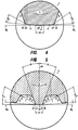
- FIG. 2 shows a schematic cross-section of a crimping granulator 1.
- the crimping granulator 1 has two housing halves 45 and 46, wherein an upper housing half 45 is arranged pivotably relative to a lower housing half 46.
- the lower housing half 46 may be arranged on a machine frame.
- the cylindrical pressure roller 2 is rotatably mounted, while in the upper housing half 45, the driven provided with a toothing 4 nip roller 3 is arranged.
- the upper housing half 45 has a pressure mechanism 47, with the nip roller 3 in the closed state of the housing the pressure roller 2 can be varied by changing a minimum distance a or changing a contact pressure between the cylindrical surface 36 of the pressure roller 2 and the tooth tip portions 8 of the nip roller 3 by means of a hydraulic or pneumatic cylinder 48.
- a hydraulic or pneumatic cylinder 48 With the pressure mechanism 47, the pinch areas and their possible squish thickness can be adapted to the respective material of the buffer tube for optimum production of sealing seams and of predetermined breaking profiles.
- an electromechanical actuator can also be used.
- the axes 49 and 51 of the pressure roller 2 and the nip roller 3 are mounted axially parallel in the housing halves 45 and 46.
- the nip roll 3 has a toothing 4 which has a tooth root region 7 and a tooth tip region 8.
- the tooth tip region 8 has three pinch zones 9, 10 and 11, as shown in detail in the other figures.
- the pinch zones 9, 10 and 11 have an input pinch zone 9, a center pinch zone 10 and an exit pinch zone 11.
- the center crimping zone 10 is disposed between the entrance crimping zone 9 and the exit crimping zone 11 and defines the smallest distance a between the crimping roller 3 and the platen roller 2 when the platen mechanism 47 is stationary. This smallest distance depends on the corresponding contact pressure between the center crimping zone 10 and the cylindrical surface of the platen roller , processing temperature and material properties such as material thickness and plasticity at the processing temperature.
- a water jet nozzle 52 is arranged in the lower housing half 46, which directs tempered water on the nip in order to assist the welding process in the formation of sealing seams.
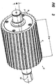
- FIG. 3 shows a schematic perspective view of a squeezing roller 3 of the crimping granulator, as shown in FIG. 1 and 2 you can see.
- the width B of the nip roll 3 is dimensioned such that at the same time a plurality of plastic strands can be processed parallel to granules cushion.
- the toothing 4 is the Squeezing roller 3 formed as helical teeth with a so-called spiral angle ⁇ with respect to the orientation of the nip roller 51st
- This helical gearing angle or helix angle ⁇ is dimensioned such that at least one tooth tip region 8 of one of the n tooth tip regions 8 of the nip roll 3 with the in FIG. 2 shown cylindrical surface 36 of the pressure roller 2 on the width B of the nip roller 3 can roll.
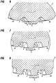
- FIG. 4 shows a schematic contour of a tooth head 8 of a nip roll 3, wherein the direction of arrow C describes the direction of rotation of the nip roll 3.
- the tooth tip region 8 is located between a tooth flank 6 rising in the direction of rotation C and a tooth flank 5 of the toothing 4 of the nip roller 3 falling in the direction of rotation.
- the inlet crushing zone 9 begins with an end 15 of the rising tooth flank 6 which at the end 15 has a chamfered input edge 21 with a Has chamfer angle ⁇ e .
- the chamfer angle ⁇ e can be between 45 ° and 15 °.
- the output squish zone 11 terminates at a beginning 16 of a sloping tooth flank 5, the beginning 16 having a chamfered exit edge 22 with a chamfer angle ⁇ a between 45 ° and 15 °, where ⁇ e and ⁇ a may have unequal amounts.
- the chamfered entrance edges 21 and exit edges 22 provide for a gentle crimping of the Hüllschlauchs while portioning the same.
- a center crush zone 10 which with its flattening 23 defines a constant minimum distance to the pressure roll in the entire area of the center crush zone 10.
- the center crush zone 10 with its minimum distance a from the pressure roller forms during portioning of the casing tube with coextruded filling compound a filling mass-free predetermined breaking profile, depending on the setting of the pressure mechanism 47, the in FIG. 2 shown may be fractions of millimeters or a few millimeters.
- FIG. 5 shows a schematic contour of the teeth 4 of the nip roller 3 in the range of Zahnfuß Schemeen 7.
- Such Zahnfuß Scheme 7 extends in a direction of rotation in the direction of arrow C from the end 13 of a sloping tooth flank 5 to the beginning 14 of a rising tooth flank 6.
- the Zahnfuß Scheme 7 can several
- a radius of 1 mm to 3 mm in the region of the end 13 of the falling tooth flank 5 and in the region of the beginning 14 of the rising tooth flank 6 are provided be to avoid microcracks by notch effect of the transitions between the tooth flanks 5 and 6 to the Zahnfuß Scheme 7.
- the tooth flanks form a flank angle ⁇ to the center line 54 of the tooth tip region 8, which can lie between 10 ° and 35 °, preferably between 15 ° and 25 °.
- the contour of the Zahnfuß Schemes 7 with the contour of the rising or falling tooth flanks 5 and 6 in cooperation with the cylindrical surface of the pressure roller form the maximum possible cross section of a producible by the squeezing granule pad from an outer shell, which is filled with a filler.
- FIGS. 4 and 5 In the further embodiments of the invention, which are constantly spaced from the pressure roller center crush zone 10 will now be in the FIGS. 6 to 8 be shown varies.
- FIG. 6 shows an alternative schematic contour of a tooth tip region 8 of the nip roller 3.
- Components with the same functions as in the FIGS. 4 and 5 are denoted by like reference numerals and will not be discussed separately.
- the center crimping zone has a web cross section 25 which projects beyond the level of the inlet crimping zone 9 and the exit crimping zone 11 and thus defines a minimum distance to the cylindrical surface of the platen roller.
- This ridge cross-section 25 of the center crimping zone can, as before, pinch a predetermined rupture seam profile into the cladding tube or even be formed in such a way that it forms a separating blade which separates the granulate rugs from one another.
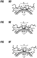
- FIG. 7 shows a further modification of the contour of the tooth tip region 8 of the nip roller 3. While both a slightly modified regardssquetschzone 9 and restrictivequetschzone 11 are provided, in the center pinch zone 10 of the tooth tip region 8 a sharp step 24 at the transition from the matterssquetschzone 9 to the center pinch zone 10 is arranged. With this sharp step 24 can also be achieved a highly effective Sollbruchnahtprofil up to shearing the granules cushion.
- the queenquetschzone 11 may be extended relative to the matterssquetschzone 9.
- FIG. 8 shows a further alternative of the contour of the tooth tip region 8 of the nip roller 3, in which similar to FIG. 7 a sharp step 24 is provided in the center crimping zone 10, but with the difference to that in FIG. 7 shown embodiment, that this stage 24 is arranged at the transition of the center pinch zone 10 to the Monquetschzone 11.
- the entrance crushing zone 9 may be extended from the exit crimping zone 11.
- FIG. 9 shows with the FIGS. 9a to 9i Manufacturing phases in a tooth tip region 8 of a roller pair 50 of a pressure roller 2 and a nip roller 3.
- the pressure roller 2 has a cylindrical surface 36 having a hardened metal alloy or a hard metal coating or ceramic coating 53.
- the tooth tip regions 8, 8 'and 8 "of the nip roll 3 are preferably surface hardened by an inductive hardening process.
- FIG. 9a Over the gap, which forms a minimum distance a between the pressure roller 2 and the nip roller 3, is like FIG. 9a shows, the beginning of a Hüllschlauchs 18 fed with a filling compound 19 to form a first media-tight Togethersquetschnaht 55 of a granular cushion to be formed.
- the buffer tube 18 with the filling compound 19 in FIG. 9b detected by a subsequent tooth tip region 8 'of the toothing 4 of the nip roller 3.
- FIG. 9a shows between the subsequent tooth tip region 8 'and the cylindrical surface 36 of the pressure roller 2 through the center crush zone 10 of the tooth tip region 8' reached and thus formed a predetermined breaking seam profile.
- the region of the tooth head 8 ' moves into the initial squeeze zone 11, which is now in FIG. 9f forming a media density second initial squeeze seam 55 'by welding for a subsequent granular pad 12'.
- FIG. 9g shown phase, in which now the contour of the granular pad 12 'between the cylindrical surface 36 of the pressure roller 2 and the contour formed from the tooth flanks 5 and 6 and the Zahnfuß Scheme 7' of the nip roller 3 is prepared, which almost the entire space between the cylindrical surface of the pressure roller 2 and the Zahnfuß Scheme 7 of the nip roller 3 fills.
- FIG. 9h shows, as soon as the inventorsquetschzone 9 of the tooth head portion 8 "of the nip roller 3, the distance between the cylindrical surface 36 of the pressure roller 2 and the tooth tip portion 8" of the nip roller 3 to a Welding distance is reduced, another Endquetschnaht 56 'of the next granular pad 12' welded.
- FIG. 3 shows, parallel to a plurality of Hüllschläuche 18, namely up to N Hüllschläuchen with N ⁇ 2B / ⁇ d are arranged side by side or parallel on the nip roller 3, where d is the outer diameter of the Hüllschlauchs.
- d is the outer diameter of the Hüllschlauchs.
Landscapes
- Engineering & Computer Science (AREA)
- Mechanical Engineering (AREA)
- Chemical & Material Sciences (AREA)
- Physics & Mathematics (AREA)
- Thermal Sciences (AREA)
- Organic Chemistry (AREA)
- Chemical Kinetics & Catalysis (AREA)
- Processing And Handling Of Plastics And Other Materials For Molding In General (AREA)
- Crushing And Grinding (AREA)
- Perforating, Stamping-Out Or Severing By Means Other Than Cutting (AREA)
Claims (15)
- Granulateur à cylindre broyeur comportant un cylindre compresseur cylindrique (2) et un cylindre broyeur denté (3), les dents (4) du cylindre broyeur (3) présentant des flancs de dents (5,6) agencés entre une zone de pied de dent (7) et une zone de tête de dent (8), la zone de pied de dent (7) présentant un diamètre extérieur (d) qui est inférieur au diamètre extérieur (D) de la zone de tête de dent (8), la zone de tête de dent (8) du cylindre broyeur (3) comportant trois zones de broyage (9, 10, 11) avec une zone de broyage centrale (10) qui définissent des écarts différents par rapport au cylindre compresseur (2) avec un écart minimal (a) dans la zone de broyage centrale (10), les contours des flancs de dents (5, 6) et de la zone de pied de dent (7) du cylindre broyeur (3) définissant, en interagissant avec les contours du cylindre compresseur (2), une section maximale d'un coussin de granulé (12) respectif à former caractérisé en ce que
la zone de pied de dent (7) s'étend d'une extrémité (13) d'un flanc de dent descendant (5) jusqu'au départ (14) d'un flanc de dent ascendant (6), et la zone de tête de dent (8) s'étend d'une extrémité (15) d'un flanc de dent ascendant (6) au départ (16) d'un flanc de dent descendant (5), les zones de broyage (9,10,11) de la zone de tête de dent (8) comportant une zone de broyage d'entrée (9) agencée dans le sens de l'alimentation, une zone de broyage de sortie (11), agencée dans le sens de l'évacuation et la zone de broyage centrale (10), agencée entre la zone de broyage d'entrée et de sortie (9, 11), les zones de broyage d'entrée et de sortie (9, 11) des dents (4) étant délimitées par les flancs de dents (6, 7), et la zone de broyage d'entrée (9) définissant un écart allant en diminuant par rapport à la zone de broyage centrale (10) et la zone de broyage de sortie (11) définissant un écart croissant par rapport au cylindre compresseur (2) en partant de la zone de broyage centrale (10) avec un angle ascendant βe pour la zone de broyage d'entrée (9) compris entre 2° et 8° et un angle descendant βa pour la zone de broyage de sortie (11) compris entre 2° et 8°, l'angle ascendant βe ayant la même valeur que l'angle descendant βa. - Granulateur à cylindre broyeur selon la revendication 1, caractérisé en ce que le granulateur à cylindre broyeur (1) comporte un dispositif d'alimentation (17) pour acheminer un tuyau d'enrobage(18) contenant une matière de remplissage co-extrudée (19), les coussins de granulés respectifs à former (12) comportant des portions de matière de remplissage (19) qui sont enrobées d'une enveloppe extérieure en matériau du tuyau d'enrobage (18).
- Granulateur à cylindre broyeur selon la revendication 1 ou la revendication 2, caractérisé en ce que la zone de broyage d'entrée (9) est configurée pour former une couture étanche d'entrée et la zone de broyage de sortie (11) pour former une couture étanche de sortie sur les coussins de granulés respectifs (12) à former et la zone de broyage centrale (10) pour former un profil de couture de rupture entre les coussins de granulés respectifs (12) à former.
- Granulateur à cylindre broyeur selon une des revendications précédentes, caractérisé en ce que la zone de tête de dent (8) présente une arête d'entrée (21) en biseau par rapport à la zone de broyage d'entrée (9) et une arête de sortie (22) en biseau par rapport à la zone de broyage de sortie (11).
- Granulateur à cylindre broyeur selon une des revendications précédentes, caractérisé en ce que la zone de broyage centrale (10) de la zone de tête de dent (8) du cylindre broyeur (3) présente un aplat (23) comme profil de couture de rupture.
- Granulateur à cylindre broyeur selon une des revendications 1 à 4, caractérisé en ce que la zone de broyage centrale (10) de la zone de tête de dent (8) du cylindre broyeur (3) présente un décrochement (24) comme profil de couture de rupture.
- Granulateur à cylindre broyeur selon une des revendications 1 à 4, caractérisé en ce que la zone de broyage centrale (10) de la zone de tête de dent (8) du cylindre broyeur (3) présente une section de nervure (25) faisant saillie au-dessus de la zone de broyage d'entrée (9) et de la zone de broyage de sortie (11).
- Granulateur à cylindre broyeur selon une des revendications précédentes, caractérisé en ce que la zone de broyage de sortie (11) est plus longue que la zone de broyage d'entrée (9).
- Granulateur à cylindre broyeur selon une des revendications précédentes, caractérisé en ce que le cylindre broyeur (3) et le cylindre compresseur (2) présentent un alliage métallique, la surface cylindrique du cylindre compresseur (2) et les zones de têtes de dents (8) du cylindre broyeur (3) présentant des surfaces résistantes à l'usure, de préférence des surfaces trempées ou des surfaces de revêtement en métaux durs ou revêtement céramique.
- Granulateur à cylindre broyeur selon une des revendications 2 à 9, caractérisé en ce que le tuyau d'enrobage (18) est en des matériaux thermoplastiques du groupe polyamide (PA), polypropylène (PP), polyéthylène faible densité (LDPE), copolymère, ou éthylène-copolymère alcool de vinyle (EVOH), copolymère éthylène acétate de vinyle (EVA) ou en mélanges de ces produits avec des proportions de cire polyoléfine, de cire polyéthylène, cire polypropylène ou dérivés d'acides gras.
- Granulateur à cylindre broyeur selon une des revendications précédentes, caractérisé en ce que
le cylindre broyeur (3) comporte des dents hélicoïdales (26) avec un angle de dents hélicoïdales α compris entre
- Granulateur à cylindre broyeur selon une des revendications précédentes, caractérisé en ce qu'un coussin de granulés (12) présente une longueur l de


N étant
- Installation de granulation avec un granulateur à cylindre broyeur selon une des revendications 1 à 12, caractérisée en ce que l'installation de granulation (100) comporte une extrudeuse (27) pour la co-extrusion de matière de remplissage (19) dans des tuyaux d'enrobage (18) en des boudins de matière plastique (28), un dispositif d'alimentation (17) pour acheminer les boudins de matière plastique (28) vers une paire de cylindres composée du cylindre compresseur (2) et du cylindre broyeur denté (3), un entraînement pour le cylindre broyeur (3) et un dispositif de collecte (29) pour recevoir les boudins de matière plastique (28) divisés en coussins de granulés (12) par la paire de cylindres constitués d'une enveloppe extérieure et une matière de remplissage co-extrudée (19), un dispositif de commande et de régulation du granulateur à cylindre broyeur (1) coordonnant l'entraînement du cylindre broyeur (3) avec la vitesse d'extrusion des boudins de matière plastique(28).
- Utilisation du granulateur à cylindre broyeur(1) selon une des revendications précédentes pour la fabrication de coussins de granulés (12) contenant une matière de remplissage (19) pulvérulente, liquide, visqueuse ou plastique.
- Utilisation du granulateur à cylindre broyeur (1) selon une des revendications 1 à 13 pour la répartition en portions de matière de remplissage (19) pharmaceutique, médicamenteuse, cosmétique, adhésive ou emballée stérilement dans des coussins de granulés (12) avec une enveloppe extérieure.
Applications Claiming Priority (2)
| Application Number | Priority Date | Filing Date | Title |
|---|---|---|---|
| DE102013003032.3A DE102013003032A1 (de) | 2013-02-22 | 2013-02-22 | Quetschwalzengranulator und Verwendung desselben |
| PCT/EP2014/000446 WO2014127914A1 (fr) | 2013-02-22 | 2014-02-19 | Granulateur à cylindres broyeurs et son utilisation |
Publications (2)
| Publication Number | Publication Date |
|---|---|
| EP2958723A1 EP2958723A1 (fr) | 2015-12-30 |
| EP2958723B1 true EP2958723B1 (fr) | 2018-10-24 |
Family
ID=50184875
Family Applications (1)
| Application Number | Title | Priority Date | Filing Date |
|---|---|---|---|
| EP14706781.3A Active EP2958723B1 (fr) | 2013-02-22 | 2014-02-19 | Granulateur à cylindres broyeurs et son utilisation |
Country Status (7)
| Country | Link |
|---|---|
| US (1) | US20160046040A1 (fr) |
| EP (1) | EP2958723B1 (fr) |
| KR (1) | KR102175976B1 (fr) |
| CN (1) | CN105073362B (fr) |
| BR (1) | BR112015019897A2 (fr) |
| DE (1) | DE102013003032A1 (fr) |
| WO (1) | WO2014127914A1 (fr) |
Families Citing this family (14)
| Publication number | Priority date | Publication date | Assignee | Title |
|---|---|---|---|---|
| DE202014008800U1 (de) * | 2014-11-05 | 2014-11-17 | Automatik Plastics Machinery Gmbh | Quetschwalzengranulator mit Quetschwalzenpaar und Verwendung desselben |
| CN105344290B (zh) * | 2015-10-10 | 2017-09-26 | 重庆国农环境科技股份有限公司 | 肥丸制造装置 |
| CN106422972A (zh) * | 2016-08-29 | 2017-02-22 | 天津特斯达生物质能源机械有限公司 | 一种挤压模及旋转条型柱塞式秸秆制粒机 |
| US11400457B2 (en) * | 2018-07-20 | 2022-08-02 | Phiston Technologies, Inc. | Solid state drive media destroyer |
| US11388909B2 (en) | 2018-10-02 | 2022-07-19 | Pure Nature Foods, LLC | Apparatus and method for post-extrusion filling and closure of an extrudate |
| US10657345B1 (en) | 2019-07-02 | 2020-05-19 | Phiston Technologies, Inc. | Media destruction verification apparatus |
| CN110549512B (zh) * | 2019-08-30 | 2021-05-28 | 嘉兴北化高分子助剂有限公司 | 一种橡胶助剂母胶粒挤压造粒机 |
| CN111434782B (zh) * | 2019-11-18 | 2024-04-12 | 石河子大学 | 一种四辊甘蔗压榨机 |
| CN111037775A (zh) * | 2019-12-30 | 2020-04-21 | 广东国珑新材料科技有限公司 | 一种阻燃材料全自动生产线 |
| CN112297276A (zh) * | 2020-03-11 | 2021-02-02 | 高雪 | 一种废旧塑料颗粒再生造粒切割装置 |
| CN113198389B (zh) * | 2021-04-22 | 2022-03-25 | 江苏鹏鹞药业有限公司 | 一种制药干法制粒机的挤压装置及其挤压方法 |
| CN113304688B (zh) * | 2021-05-25 | 2022-11-18 | 湖北庄康生物科技股份有限公司 | 一种使用有机肥造粒机挤压辊机构提高颗粒紧密度的方法 |
| CN116476265B (zh) * | 2023-03-20 | 2025-12-30 | 常州爱特恩新材料科技有限公司 | 一种晶须增强聚丙烯pp材料的造粒设备及造粒方法 |
| CN119034604B (zh) * | 2024-10-29 | 2025-01-28 | 内蒙古垣吉化工有限公司 | 一种费托蜡用造粒机 |
Citations (2)
| Publication number | Priority date | Publication date | Assignee | Title |
|---|---|---|---|---|
| JPS5981120A (ja) * | 1982-11-01 | 1984-05-10 | Toyo Seikan Kaisha Ltd | 成形用被覆樹脂ペレツト及びその製造法 |
| EP0143414A2 (fr) * | 1983-11-25 | 1985-06-05 | Blohm + Voss Ag | Machine à agglomérer |
Family Cites Families (18)
| Publication number | Priority date | Publication date | Assignee | Title |
|---|---|---|---|---|
| DE1297525B (de) | 1965-06-05 | 1969-06-12 | Hansen Gerhard | Verfahren und Vorrichtung zum kontinuierlichen Herstellen, Fuellen und Verschliessen von Behaeltern aus Kunststoff, insbesondere Polyaethylen |
| US3561050A (en) * | 1968-05-03 | 1971-02-09 | Corson G & W H | Pellet machine |
| DE2554239A1 (de) * | 1975-12-03 | 1977-06-16 | Dynamit Nobel Ag | Verfahren und vorrichtung zum ummanteln eines extrudierten kernprofiles aus kunststoff |
| DE2627263C2 (de) * | 1976-06-18 | 1978-08-10 | Automatik Apparate-Maschinenbau H. Hench Gmbh, 8754 Grossostheim | Vorrichtung zum Abkühlen und Granulieren von Strängen aus thermoplastischen Kunststoffen |
| US4219291A (en) * | 1979-03-14 | 1980-08-26 | Hoeh James A | Segmented helical rotary cutter and method of making same |
| JPS6026001B2 (ja) * | 1979-06-12 | 1985-06-21 | 東芝機械株式会社 | 被覆粒状物の成形装置 |
| DE3145614C2 (de) | 1981-11-17 | 1984-06-28 | Automatik Apparate-Maschinenbau H. Hench Gmbh, 8754 Grossostheim | Vorrichtung zum Granulieren von Strängen aus Kunststoffmaterial und ähnlichen plastischen Massen |
| DE3622053A1 (de) * | 1985-07-01 | 1987-01-15 | Kobe Steel Ltd | Verdichtungsgeraet |
| DE3612211A1 (de) * | 1986-04-11 | 1987-10-15 | Basf Ag | Kontinuierliches verfahren zum tablettieren |
| ATE142938T1 (de) * | 1988-06-09 | 1996-10-15 | American National Can Co | Verfahren zum herstellen von mehrschichtigen folienmaterialien, verfahren zur verarbeitung von polymeren, extrusionsvorrichtung, polymerisches folienmaterial und hiermit hergestellte verpackung |
| DE3832566A1 (de) | 1988-09-24 | 1990-04-05 | Bernd Hansen | Verfahren zum herstellen gefuellter fluessigkeitsbehaelter aus thermoplastischem kunststoff sowie extrusionskopf |
| DE19931222C2 (de) * | 1999-07-06 | 2002-08-01 | Rieter Automatik Gmbh | Vorrichtung zum Granulieren von Kunststoffsträngen |
| US6612825B2 (en) * | 2001-09-07 | 2003-09-02 | American Extrusion International Corp. | Pillow cutting extruder machine |
| DE10347908A1 (de) | 2003-10-15 | 2005-05-19 | Bernd Hansen | Verfahren und Vorrichtung zur Herstellung mindestens eines mit einem Medium befüllten Behälters |
| BRPI0418907A (pt) * | 2004-05-20 | 2007-11-27 | Albemarle Corp | aglomerados de polìmeros estirênicos aniÈnicos bromatadas inalterados e método de preparação |
| JP4571531B2 (ja) * | 2005-03-28 | 2010-10-27 | 住化カラー株式会社 | 複層押出成形品の押出装置およびそれを用いた複層押出成形品の製造方法 |
| JP2008068517A (ja) * | 2006-09-14 | 2008-03-27 | Mitsubishi Chemicals Corp | 樹脂ペレットの製造方法 |
| WO2012157392A1 (fr) * | 2011-05-18 | 2012-11-22 | 東洋製罐株式会社 | Système de coupage de résine fondue |
-
2013
- 2013-02-22 DE DE102013003032.3A patent/DE102013003032A1/de not_active Withdrawn
-
2014
- 2014-02-19 EP EP14706781.3A patent/EP2958723B1/fr active Active
- 2014-02-19 BR BR112015019897A patent/BR112015019897A2/pt not_active IP Right Cessation
- 2014-02-19 KR KR1020157023987A patent/KR102175976B1/ko active Active
- 2014-02-19 CN CN201480010065.2A patent/CN105073362B/zh active Active
- 2014-02-19 WO PCT/EP2014/000446 patent/WO2014127914A1/fr not_active Ceased
-
2015
- 2015-08-24 US US14/834,060 patent/US20160046040A1/en not_active Abandoned
Patent Citations (2)
| Publication number | Priority date | Publication date | Assignee | Title |
|---|---|---|---|---|
| JPS5981120A (ja) * | 1982-11-01 | 1984-05-10 | Toyo Seikan Kaisha Ltd | 成形用被覆樹脂ペレツト及びその製造法 |
| EP0143414A2 (fr) * | 1983-11-25 | 1985-06-05 | Blohm + Voss Ag | Machine à agglomérer |
Also Published As
| Publication number | Publication date |
|---|---|
| CN105073362A (zh) | 2015-11-18 |
| DE102013003032A1 (de) | 2014-09-25 |
| US20160046040A1 (en) | 2016-02-18 |
| BR112015019897A2 (pt) | 2017-07-18 |
| EP2958723A1 (fr) | 2015-12-30 |
| KR20150119887A (ko) | 2015-10-26 |
| WO2014127914A1 (fr) | 2014-08-28 |
| KR102175976B1 (ko) | 2020-11-09 |
| CN105073362B (zh) | 2017-11-21 |
Similar Documents
| Publication | Publication Date | Title |
|---|---|---|
| EP2958723B1 (fr) | Granulateur à cylindres broyeurs et son utilisation | |
| EP3215333B1 (fr) | Granulateur à rouleaux pinceurs, installation de granulation comprenant celui-ci et utilisation du granulateur à rouleaux pinceurs | |
| EP3782794B1 (fr) | Installation de fabrication d'une matière plastique fondue et utilisation d'une telle installation de fabrication d'une matière plastique fondue pour une feuille poreuse | |
| DE69211861T2 (de) | Farbroller und Verfahren und Vorrichtung zum Herstellen von einem Farbroller | |
| DE60130122T2 (de) | Rohrförmige mehrschichtige folien sowie verfahren und vorrichtung zu ihrer herstellung | |
| DE69717107T2 (de) | Verfahren und vorrichtung zum extrudieren eines kunststoffgegenstandes | |
| DE3820320C2 (fr) | ||
| DE102019106873B4 (de) | Extruder | |
| DE3835250C1 (fr) | ||
| EP1194278B1 (fr) | Extrudeuse a une vis | |
| WO2021023389A1 (fr) | Procédé et appareil d'extrusion destinés à l'extrusion de matière plastique renforcée par des fibres pour la fabrication additive d'un élément | |
| DE1529803B2 (de) | Schneckenstrangpresse fuer thermoplastische kunststoffe | |
| DE102012008169A1 (de) | Extruder mit Materialeintrag durch Gehäuse | |
| DE102019129717A1 (de) | Einschneckenextruder | |
| DE68927200T2 (de) | Verfahren zum Herstellen von mehrschichtigen Folienmaterialien, Verfahren zur Verarbeitung von Polymeren, Extrusionsvorrichtung, polymerisches Folienmaterial und hiermit hergestellte Verpackung | |
| DE2162229B2 (de) | Verfahren und Vorrichtung zum Einspeisen von Ausgangsstoffen in den Scherspalt von Maschinen zum Herstellen von Filmen, Bahnen, Folien oder Platten aus Kunststoff | |
| DE1145787B (de) | Schneckenstrangpresse mit einem Stauabschnitt, dessen Querschnitt veraenderlich ist | |
| EP2384879A1 (fr) | Méthode et dispositif pour former des produits tubulaires de matériau métallique ou plastique. | |
| EP2153970B1 (fr) | Procédé de fonctionnement d'une ligne d'extrusion pour profils creux en matière synthétique | |
| EP1923202B1 (fr) | Procédé et dispositif pour produire un sac tubulaire | |
| DE102006007482B4 (de) | Vorrichtung und Verfahren zur Herstellung einer rohrförmigen Umhüllung | |
| DE19929824C2 (de) | Extruder für thermoplastische Medien | |
| EP3915757A1 (fr) | Installation de soufflage de feuille comportant un agent de plastification et/ou de conditionnement comprenant un arbre central et au moins un rouleau planétaire, procédé de fabrication, bande de feuille et procédé de transformation | |
| DE112022002007T5 (de) | Maschine zum auftragen von heissschmelzprodukten | |
| WO2005016627A1 (fr) | Tete de tuyere destinee a un extrudeur |
Legal Events
| Date | Code | Title | Description |
|---|---|---|---|
| PUAI | Public reference made under article 153(3) epc to a published international application that has entered the european phase |
Free format text: ORIGINAL CODE: 0009012 |
|
| 17P | Request for examination filed |
Effective date: 20150918 |
|
| AK | Designated contracting states |
Kind code of ref document: A1 Designated state(s): AL AT BE BG CH CY CZ DE DK EE ES FI FR GB GR HR HU IE IS IT LI LT LU LV MC MK MT NL NO PL PT RO RS SE SI SK SM TR |
|
| AX | Request for extension of the european patent |
Extension state: BA ME |
|
| DAX | Request for extension of the european patent (deleted) | ||
| STAA | Information on the status of an ep patent application or granted ep patent |
Free format text: STATUS: EXAMINATION IS IN PROGRESS |
|
| 17Q | First examination report despatched |
Effective date: 20170125 |
|
| GRAP | Despatch of communication of intention to grant a patent |
Free format text: ORIGINAL CODE: EPIDOSNIGR1 |
|
| STAA | Information on the status of an ep patent application or granted ep patent |
Free format text: STATUS: GRANT OF PATENT IS INTENDED |
|
| RIC1 | Information provided on ipc code assigned before grant |
Ipc: B29B 9/16 20060101ALN20180409BHEP Ipc: B29C 47/92 20060101ALI20180409BHEP Ipc: B29C 47/06 20060101ALN20180409BHEP Ipc: B29B 9/12 20060101ALI20180409BHEP Ipc: B29C 47/88 20060101ALI20180409BHEP Ipc: B29B 9/06 20060101AFI20180409BHEP Ipc: B29C 47/00 20060101ALI20180409BHEP Ipc: B29C 47/26 20060101ALN20180409BHEP |
|
| INTG | Intention to grant announced |
Effective date: 20180507 |
|
| GRAS | Grant fee paid |
Free format text: ORIGINAL CODE: EPIDOSNIGR3 |
|
| GRAA | (expected) grant |
Free format text: ORIGINAL CODE: 0009210 |
|
| STAA | Information on the status of an ep patent application or granted ep patent |
Free format text: STATUS: THE PATENT HAS BEEN GRANTED |
|
| AK | Designated contracting states |
Kind code of ref document: B1 Designated state(s): AL AT BE BG CH CY CZ DE DK EE ES FI FR GB GR HR HU IE IS IT LI LT LU LV MC MK MT NL NO PL PT RO RS SE SI SK SM TR |
|
| REG | Reference to a national code |
Ref country code: CH Ref legal event code: EP |
|
| REG | Reference to a national code |
Ref country code: IE Ref legal event code: FG4D Free format text: LANGUAGE OF EP DOCUMENT: GERMAN |
|
| REG | Reference to a national code |
Ref country code: AT Ref legal event code: REF Ref document number: 1056140 Country of ref document: AT Kind code of ref document: T Effective date: 20181115 |
|
| REG | Reference to a national code |
Ref country code: DE Ref legal event code: R096 Ref document number: 502014009858 Country of ref document: DE |
|
| REG | Reference to a national code |
Ref country code: NL Ref legal event code: MP Effective date: 20181024 |
|
| REG | Reference to a national code |
Ref country code: LT Ref legal event code: MG4D |
|
| PG25 | Lapsed in a contracting state [announced via postgrant information from national office to epo] |
Ref country code: NL Free format text: LAPSE BECAUSE OF FAILURE TO SUBMIT A TRANSLATION OF THE DESCRIPTION OR TO PAY THE FEE WITHIN THE PRESCRIBED TIME-LIMIT Effective date: 20181024 |
|
| PG25 | Lapsed in a contracting state [announced via postgrant information from national office to epo] |
Ref country code: FI Free format text: LAPSE BECAUSE OF FAILURE TO SUBMIT A TRANSLATION OF THE DESCRIPTION OR TO PAY THE FEE WITHIN THE PRESCRIBED TIME-LIMIT Effective date: 20181024 Ref country code: HR Free format text: LAPSE BECAUSE OF FAILURE TO SUBMIT A TRANSLATION OF THE DESCRIPTION OR TO PAY THE FEE WITHIN THE PRESCRIBED TIME-LIMIT Effective date: 20181024 Ref country code: BG Free format text: LAPSE BECAUSE OF FAILURE TO SUBMIT A TRANSLATION OF THE DESCRIPTION OR TO PAY THE FEE WITHIN THE PRESCRIBED TIME-LIMIT Effective date: 20190124 Ref country code: PL Free format text: LAPSE BECAUSE OF FAILURE TO SUBMIT A TRANSLATION OF THE DESCRIPTION OR TO PAY THE FEE WITHIN THE PRESCRIBED TIME-LIMIT Effective date: 20181024 Ref country code: LT Free format text: LAPSE BECAUSE OF FAILURE TO SUBMIT A TRANSLATION OF THE DESCRIPTION OR TO PAY THE FEE WITHIN THE PRESCRIBED TIME-LIMIT Effective date: 20181024 Ref country code: NO Free format text: LAPSE BECAUSE OF FAILURE TO SUBMIT A TRANSLATION OF THE DESCRIPTION OR TO PAY THE FEE WITHIN THE PRESCRIBED TIME-LIMIT Effective date: 20190124 Ref country code: IS Free format text: LAPSE BECAUSE OF FAILURE TO SUBMIT A TRANSLATION OF THE DESCRIPTION OR TO PAY THE FEE WITHIN THE PRESCRIBED TIME-LIMIT Effective date: 20190224 Ref country code: ES Free format text: LAPSE BECAUSE OF FAILURE TO SUBMIT A TRANSLATION OF THE DESCRIPTION OR TO PAY THE FEE WITHIN THE PRESCRIBED TIME-LIMIT Effective date: 20181024 Ref country code: LV Free format text: LAPSE BECAUSE OF FAILURE TO SUBMIT A TRANSLATION OF THE DESCRIPTION OR TO PAY THE FEE WITHIN THE PRESCRIBED TIME-LIMIT Effective date: 20181024 |
|
| PG25 | Lapsed in a contracting state [announced via postgrant information from national office to epo] |
Ref country code: AL Free format text: LAPSE BECAUSE OF FAILURE TO SUBMIT A TRANSLATION OF THE DESCRIPTION OR TO PAY THE FEE WITHIN THE PRESCRIBED TIME-LIMIT Effective date: 20181024 Ref country code: SE Free format text: LAPSE BECAUSE OF FAILURE TO SUBMIT A TRANSLATION OF THE DESCRIPTION OR TO PAY THE FEE WITHIN THE PRESCRIBED TIME-LIMIT Effective date: 20181024 Ref country code: RS Free format text: LAPSE BECAUSE OF FAILURE TO SUBMIT A TRANSLATION OF THE DESCRIPTION OR TO PAY THE FEE WITHIN THE PRESCRIBED TIME-LIMIT Effective date: 20181024 Ref country code: GR Free format text: LAPSE BECAUSE OF FAILURE TO SUBMIT A TRANSLATION OF THE DESCRIPTION OR TO PAY THE FEE WITHIN THE PRESCRIBED TIME-LIMIT Effective date: 20190125 Ref country code: PT Free format text: LAPSE BECAUSE OF FAILURE TO SUBMIT A TRANSLATION OF THE DESCRIPTION OR TO PAY THE FEE WITHIN THE PRESCRIBED TIME-LIMIT Effective date: 20190224 |
|
| REG | Reference to a national code |
Ref country code: DE Ref legal event code: R097 Ref document number: 502014009858 Country of ref document: DE |
|
| PG25 | Lapsed in a contracting state [announced via postgrant information from national office to epo] |
Ref country code: DK Free format text: LAPSE BECAUSE OF FAILURE TO SUBMIT A TRANSLATION OF THE DESCRIPTION OR TO PAY THE FEE WITHIN THE PRESCRIBED TIME-LIMIT Effective date: 20181024 Ref country code: CZ Free format text: LAPSE BECAUSE OF FAILURE TO SUBMIT A TRANSLATION OF THE DESCRIPTION OR TO PAY THE FEE WITHIN THE PRESCRIBED TIME-LIMIT Effective date: 20181024 |
|
| PG25 | Lapsed in a contracting state [announced via postgrant information from national office to epo] |
Ref country code: RO Free format text: LAPSE BECAUSE OF FAILURE TO SUBMIT A TRANSLATION OF THE DESCRIPTION OR TO PAY THE FEE WITHIN THE PRESCRIBED TIME-LIMIT Effective date: 20181024 Ref country code: SK Free format text: LAPSE BECAUSE OF FAILURE TO SUBMIT A TRANSLATION OF THE DESCRIPTION OR TO PAY THE FEE WITHIN THE PRESCRIBED TIME-LIMIT Effective date: 20181024 Ref country code: SM Free format text: LAPSE BECAUSE OF FAILURE TO SUBMIT A TRANSLATION OF THE DESCRIPTION OR TO PAY THE FEE WITHIN THE PRESCRIBED TIME-LIMIT Effective date: 20181024 Ref country code: EE Free format text: LAPSE BECAUSE OF FAILURE TO SUBMIT A TRANSLATION OF THE DESCRIPTION OR TO PAY THE FEE WITHIN THE PRESCRIBED TIME-LIMIT Effective date: 20181024 |
|
| PLBE | No opposition filed within time limit |
Free format text: ORIGINAL CODE: 0009261 |
|
| STAA | Information on the status of an ep patent application or granted ep patent |
Free format text: STATUS: NO OPPOSITION FILED WITHIN TIME LIMIT |
|
| REG | Reference to a national code |
Ref country code: CH Ref legal event code: PL |
|
| 26N | No opposition filed |
Effective date: 20190725 |
|
| GBPC | Gb: european patent ceased through non-payment of renewal fee |
Effective date: 20190219 |
|
| PG25 | Lapsed in a contracting state [announced via postgrant information from national office to epo] |
Ref country code: LU Free format text: LAPSE BECAUSE OF NON-PAYMENT OF DUE FEES Effective date: 20190219 Ref country code: SI Free format text: LAPSE BECAUSE OF FAILURE TO SUBMIT A TRANSLATION OF THE DESCRIPTION OR TO PAY THE FEE WITHIN THE PRESCRIBED TIME-LIMIT Effective date: 20181024 Ref country code: MC Free format text: LAPSE BECAUSE OF FAILURE TO SUBMIT A TRANSLATION OF THE DESCRIPTION OR TO PAY THE FEE WITHIN THE PRESCRIBED TIME-LIMIT Effective date: 20181024 |
|
| REG | Reference to a national code |
Ref country code: BE Ref legal event code: MM Effective date: 20190228 |
|
| REG | Reference to a national code |
Ref country code: IE Ref legal event code: MM4A |
|
| PG25 | Lapsed in a contracting state [announced via postgrant information from national office to epo] |
Ref country code: CH Free format text: LAPSE BECAUSE OF NON-PAYMENT OF DUE FEES Effective date: 20190228 Ref country code: LI Free format text: LAPSE BECAUSE OF NON-PAYMENT OF DUE FEES Effective date: 20190228 |
|
| PG25 | Lapsed in a contracting state [announced via postgrant information from national office to epo] |
Ref country code: IE Free format text: LAPSE BECAUSE OF NON-PAYMENT OF DUE FEES Effective date: 20190219 Ref country code: GB Free format text: LAPSE BECAUSE OF NON-PAYMENT OF DUE FEES Effective date: 20190219 |
|
| PG25 | Lapsed in a contracting state [announced via postgrant information from national office to epo] |
Ref country code: FR Free format text: LAPSE BECAUSE OF NON-PAYMENT OF DUE FEES Effective date: 20190228 Ref country code: BE Free format text: LAPSE BECAUSE OF NON-PAYMENT OF DUE FEES Effective date: 20190228 |
|
| REG | Reference to a national code |
Ref country code: DE Ref legal event code: R082 Ref document number: 502014009858 Country of ref document: DE Representative=s name: PUSCHMANN BORCHERT KAISER KLETTNER PATENTANWAE, DE Ref country code: DE Ref legal event code: R082 Ref document number: 502014009858 Country of ref document: DE Representative=s name: KUHNEN & WACKER PATENT- UND RECHTSANWALTSBUERO, DE Ref country code: DE Ref legal event code: R082 Ref document number: 502014009858 Country of ref document: DE Representative=s name: PUSCHMANN BORCHERT BARDEHLE PATENTANWAELTE PAR, DE |
|
| PG25 | Lapsed in a contracting state [announced via postgrant information from national office to epo] |
Ref country code: TR Free format text: LAPSE BECAUSE OF FAILURE TO SUBMIT A TRANSLATION OF THE DESCRIPTION OR TO PAY THE FEE WITHIN THE PRESCRIBED TIME-LIMIT Effective date: 20181024 |
|
| REG | Reference to a national code |
Ref country code: AT Ref legal event code: MM01 Ref document number: 1056140 Country of ref document: AT Kind code of ref document: T Effective date: 20190219 |
|
| PG25 | Lapsed in a contracting state [announced via postgrant information from national office to epo] |
Ref country code: AT Free format text: LAPSE BECAUSE OF NON-PAYMENT OF DUE FEES Effective date: 20190219 |
|
| REG | Reference to a national code |
Ref country code: DE Ref legal event code: R082 Ref document number: 502014009858 Country of ref document: DE Representative=s name: PUSCHMANN BORCHERT KAISER KLETTNER PATENTANWAE, DE Ref legal event code: R082 Ref document number: 502014009858 Country of ref document: DE Ref country code: DE Ref legal event code: R082 Ref document number: 502014009858 Country of ref document: DE Representative=s name: PUSCHMANN BORCHERT BARDEHLE PATENTANWAELTE PAR, DE |
|
| PG25 | Lapsed in a contracting state [announced via postgrant information from national office to epo] |
Ref country code: MT Free format text: LAPSE BECAUSE OF FAILURE TO SUBMIT A TRANSLATION OF THE DESCRIPTION OR TO PAY THE FEE WITHIN THE PRESCRIBED TIME-LIMIT Effective date: 20181024 |
|
| REG | Reference to a national code |
Ref country code: DE Ref legal event code: R082 Ref document number: 502014009858 Country of ref document: DE Representative=s name: PUSCHMANN BORCHERT KAISER KLETTNER PATENTANWAE, DE |
|
| PG25 | Lapsed in a contracting state [announced via postgrant information from national office to epo] |
Ref country code: CY Free format text: LAPSE BECAUSE OF FAILURE TO SUBMIT A TRANSLATION OF THE DESCRIPTION OR TO PAY THE FEE WITHIN THE PRESCRIBED TIME-LIMIT Effective date: 20181024 |
|
| PG25 | Lapsed in a contracting state [announced via postgrant information from national office to epo] |
Ref country code: HU Free format text: LAPSE BECAUSE OF FAILURE TO SUBMIT A TRANSLATION OF THE DESCRIPTION OR TO PAY THE FEE WITHIN THE PRESCRIBED TIME-LIMIT; INVALID AB INITIO Effective date: 20140219 |
|
| PG25 | Lapsed in a contracting state [announced via postgrant information from national office to epo] |
Ref country code: MK Free format text: LAPSE BECAUSE OF FAILURE TO SUBMIT A TRANSLATION OF THE DESCRIPTION OR TO PAY THE FEE WITHIN THE PRESCRIBED TIME-LIMIT Effective date: 20181024 |
|
| PGFP | Annual fee paid to national office [announced via postgrant information from national office to epo] |
Ref country code: DE Payment date: 20260218 Year of fee payment: 13 |
|
| PGFP | Annual fee paid to national office [announced via postgrant information from national office to epo] |
Ref country code: IT Payment date: 20260224 Year of fee payment: 13 |