EP2960487A1 - Soupape d'injection de carburant pour moteurs à combustion interne - Google Patents
Soupape d'injection de carburant pour moteurs à combustion interne Download PDFInfo
- Publication number
- EP2960487A1 EP2960487A1 EP15166910.8A EP15166910A EP2960487A1 EP 2960487 A1 EP2960487 A1 EP 2960487A1 EP 15166910 A EP15166910 A EP 15166910A EP 2960487 A1 EP2960487 A1 EP 2960487A1
- Authority
- EP
- European Patent Office
- Prior art keywords
- spring
- nozzle
- nozzle needle
- sleeve
- injection valve
- Prior art date
- Legal status (The legal status is an assumption and is not a legal conclusion. Google has not performed a legal analysis and makes no representation as to the accuracy of the status listed.)
- Granted
Links
Images

Classifications
-
- F—MECHANICAL ENGINEERING; LIGHTING; HEATING; WEAPONS; BLASTING
- F02—COMBUSTION ENGINES; HOT-GAS OR COMBUSTION-PRODUCT ENGINE PLANTS
- F02M—SUPPLYING COMBUSTION ENGINES IN GENERAL WITH COMBUSTIBLE MIXTURES OR CONSTITUENTS THEREOF
- F02M61/00—Fuel-injectors not provided for in groups F02M39/00 - F02M57/00 or F02M67/00
- F02M61/16—Details not provided for in, or of interest apart from, the apparatus of groups F02M61/02 - F02M61/14
- F02M61/20—Closing valves mechanically, e.g. arrangements of springs or weights or permanent magnets; Damping of valve lift
-
- F—MECHANICAL ENGINEERING; LIGHTING; HEATING; WEAPONS; BLASTING
- F02—COMBUSTION ENGINES; HOT-GAS OR COMBUSTION-PRODUCT ENGINE PLANTS
- F02M—SUPPLYING COMBUSTION ENGINES IN GENERAL WITH COMBUSTIBLE MIXTURES OR CONSTITUENTS THEREOF
- F02M51/00—Fuel-injection apparatus characterised by being operated electrically
- F02M51/06—Injectors peculiar thereto with means directly operating the valve needle
- F02M51/061—Injectors peculiar thereto with means directly operating the valve needle using electromagnetic operating means
- F02M51/0625—Injectors peculiar thereto with means directly operating the valve needle using electromagnetic operating means characterised by arrangement of mobile armatures
- F02M51/0664—Injectors peculiar thereto with means directly operating the valve needle using electromagnetic operating means characterised by arrangement of mobile armatures having a cylindrically or partly cylindrically shaped armature, e.g. entering the winding; having a plate-shaped or undulated armature entering the winding
- F02M51/0671—Injectors peculiar thereto with means directly operating the valve needle using electromagnetic operating means characterised by arrangement of mobile armatures having a cylindrically or partly cylindrically shaped armature, e.g. entering the winding; having a plate-shaped or undulated armature entering the winding the armature having an elongated valve body attached thereto
- F02M51/0675—Injectors peculiar thereto with means directly operating the valve needle using electromagnetic operating means characterised by arrangement of mobile armatures having a cylindrically or partly cylindrically shaped armature, e.g. entering the winding; having a plate-shaped or undulated armature entering the winding the armature having an elongated valve body attached thereto the valve body having cylindrical guiding or metering portions, e.g. with fuel passages
-
- F—MECHANICAL ENGINEERING; LIGHTING; HEATING; WEAPONS; BLASTING
- F02—COMBUSTION ENGINES; HOT-GAS OR COMBUSTION-PRODUCT ENGINE PLANTS
- F02M—SUPPLYING COMBUSTION ENGINES IN GENERAL WITH COMBUSTIBLE MIXTURES OR CONSTITUENTS THEREOF
- F02M61/00—Fuel-injectors not provided for in groups F02M39/00 - F02M57/00 or F02M67/00
- F02M61/04—Fuel-injectors not provided for in groups F02M39/00 - F02M57/00 or F02M67/00 having valves, e.g. having a plurality of valves in series
- F02M61/10—Other injectors with elongated valve bodies, i.e. of needle-valve type
- F02M61/12—Other injectors with elongated valve bodies, i.e. of needle-valve type characterised by the provision of guiding or centring means for valve bodies
-
- F—MECHANICAL ENGINEERING; LIGHTING; HEATING; WEAPONS; BLASTING
- F02—COMBUSTION ENGINES; HOT-GAS OR COMBUSTION-PRODUCT ENGINE PLANTS
- F02M—SUPPLYING COMBUSTION ENGINES IN GENERAL WITH COMBUSTIBLE MIXTURES OR CONSTITUENTS THEREOF
- F02M61/00—Fuel-injectors not provided for in groups F02M39/00 - F02M57/00 or F02M67/00
- F02M61/16—Details not provided for in, or of interest apart from, the apparatus of groups F02M61/02 - F02M61/14
- F02M61/161—Means for adjusting injection-valve lift
-
- F—MECHANICAL ENGINEERING; LIGHTING; HEATING; WEAPONS; BLASTING
- F02—COMBUSTION ENGINES; HOT-GAS OR COMBUSTION-PRODUCT ENGINE PLANTS
- F02M—SUPPLYING COMBUSTION ENGINES IN GENERAL WITH COMBUSTIBLE MIXTURES OR CONSTITUENTS THEREOF
- F02M63/00—Other fuel-injection apparatus having pertinent characteristics not provided for in groups F02M39/00 - F02M57/00 or F02M67/00; Details, component parts, or accessories of fuel-injection apparatus, not provided for in, or of interest apart from, the apparatus of groups F02M39/00 - F02M61/00 or F02M67/00; Combination of fuel pump with other devices, e.g. lubricating oil pump
- F02M63/0012—Valves
- F02M63/007—Details not provided for in, or of interest apart from, the apparatus of the groups F02M63/0014 - F02M63/0059
- F02M63/0075—Stop members in valves, e.g. plates or disks limiting the movement of armature, valve or spring
-
- F—MECHANICAL ENGINEERING; LIGHTING; HEATING; WEAPONS; BLASTING
- F02—COMBUSTION ENGINES; HOT-GAS OR COMBUSTION-PRODUCT ENGINE PLANTS
- F02M—SUPPLYING COMBUSTION ENGINES IN GENERAL WITH COMBUSTIBLE MIXTURES OR CONSTITUENTS THEREOF
- F02M2200/00—Details of fuel-injection apparatus, not otherwise provided for
- F02M2200/50—Arrangements of springs for valves used in fuel injectors or fuel injection pumps
-
- F—MECHANICAL ENGINEERING; LIGHTING; HEATING; WEAPONS; BLASTING
- F02—COMBUSTION ENGINES; HOT-GAS OR COMBUSTION-PRODUCT ENGINE PLANTS
- F02M—SUPPLYING COMBUSTION ENGINES IN GENERAL WITH COMBUSTIBLE MIXTURES OR CONSTITUENTS THEREOF
- F02M2200/00—Details of fuel-injection apparatus, not otherwise provided for
- F02M2200/70—Linkage between actuator and actuated element, e.g. between piezoelectric actuator and needle valve or pump plunger
- F02M2200/703—Linkage between actuator and actuated element, e.g. between piezoelectric actuator and needle valve or pump plunger hydraulic
- F02M2200/708—Linkage between actuator and actuated element, e.g. between piezoelectric actuator and needle valve or pump plunger hydraulic with hydraulic chambers formed by a movable sleeve
-
- F—MECHANICAL ENGINEERING; LIGHTING; HEATING; WEAPONS; BLASTING
- F02—COMBUSTION ENGINES; HOT-GAS OR COMBUSTION-PRODUCT ENGINE PLANTS
- F02M—SUPPLYING COMBUSTION ENGINES IN GENERAL WITH COMBUSTIBLE MIXTURES OR CONSTITUENTS THEREOF
- F02M2547/00—Special features for fuel-injection valves actuated by fluid pressure
- F02M2547/001—Control chambers formed by movable sleeves
Definitions
- the invention relates to a fuel injection valve, as it is used in particular for fuel injection in combustion chambers of high-speed, self-igniting internal combustion engines.
- Fuel injection valves which finely atomize fuel under high pressure and thus introduce the fuel into a combustion chamber of an internal combustion engine are known in the art.
- a nozzle needle is arranged longitudinally movable within a nozzle body, the one or more injection openings due to their longitudinal movement and heading.
- the longitudinal movement of the compressed and located within the nozzle fuel is metered through the injection openings, wherein the amount and timing of the injection are controlled by the longitudinal movement of the nozzle needle.
- the nozzle needle is spring-loaded in the closing direction, as for example from the published patent application DE 100 24 703 A1 is known.
- the closing spring surrounds the nozzle needle and is supported with the end facing away from the injection openings on a sleeve which surrounds the end of the nozzle needle remote from the combustion chamber and thereby delimits a control chamber.
- the actual closing force on the nozzle needle is exerted by the fuel pressure within this control chamber, the pressure of which can be regulated by means of a control valve.
- the spring force of the closing spring which surrounds the nozzle needle, influences the opening and closing behavior of the nozzle needle, even if the closing spring applies only a part of the forces influencing the nozzle needle.
- the force of the nozzle spring must therefore be large enough to safely press the sleeve against this component, usually the throttle plate, thereby achieving a reliable seal, for which a greater force is necessary.
- the nozzle spring exerts a closing force on the nozzle needle, which presses them against the nozzle seat.
- This spring force must be known so that the nozzle can be properly designed and works in the desired manner, but here only a small closing force is required and desired to be able to move the nozzle needle from its closed position without delay.
- the spring constant and the bias of the nozzle spring are thus a compromise to optimally fulfill both functions of the nozzle spring.
- a fuel injection valve which is responsible for the closing force on the nozzle needle is from the Scriptures DE 10 2012 205 696 A1 a fuel injection valve is known in which the nozzle needle is surrounded by two different springs: A nozzle spring, which is supported at one end to a stationary housing part and which acts on the other end of the nozzle needle and thereby causes a closing force on the nozzle needle.
- a second spring is provided, which also surrounds the nozzle needle and which presses the sleeve, which receives the combustion chamber facing away from the end of the nozzle needle, against the adjacent throttle disc and thereby seals the control chamber.
- the fuel is guided in this fuel injection valve through a longitudinal channel, which is formed within the nozzle needle.
- this solution is complex and therefore expensive to manufacture.
- the fuel is conducted past between the nozzle needle and the wall of the pressure chamber, the fuel flows through the nozzle spring, which is designed to be relatively weak and which can thus be appreciably influenced by the passing fuel.
- transverse forces are applied to the spring, which can cause scattering of the injection characteristic from stroke to stroke.
- the fuel injection valve has the advantage that the fuel flowing through the pressure chamber of the nozzle body in the direction of the injection openings, no longer affects the nozzle spring and thus there is no fluctuations from hub to hub due to different forces of the flowing fuel on the nozzle spring .
- the fuel injection valve has a housing in which a pressure space can be filled with fuel under high pressure, in which a nozzle needle for opening and closing at least one injection opening is arranged longitudinally movable, wherein the nozzle needle is guided in the opening of a guide disc.
- a nozzle spring is arranged under pressure bias between the guide plate and a spring plate, wherein the spring plate is supported on the nozzle needle, so that the nozzle spring exerts a closing force on the nozzle needle.
- the spring plate has a sleeve-shaped extension on which a guide disk facing stop surface is formed, wherein the sleeve-shaped extension of the spring plate surrounds the nozzle spring at least partially.
- the fuel is prevented from flowing when flowing in the direction of the injection openings through the nozzle spring or directly past this. This avoids that the flowing fuel exerts forces on the nozzle spring, in particular no transverse forces that would transfer to the nozzle needle and would affect the opening behavior.
- the abutment surface comes to the sleeve-shaped extension of the spring plate after passing through a maximum stroke of the nozzle needle on the guide disc to the plant.
- the maximum stroke of the nozzle needle is limited, on the other hand, a good shielding of the nozzle spring against the fuel flow within the nozzle chamber is achieved by the plant of the sleeve-shaped extension on the guide disk.
- holes are further advantageously formed within the guide plate through which the fuel can flow. The holes are more advantageous Way arranged so that the fuel stream flowing through them passes between the spring plate and the wall of the pressure chamber.
- a plurality of holes in the guide disc is formed, which are distributed over the circumference of the guide disc. This serves on the one hand to equalize the flow to exclude lateral forces on the nozzle needle, and on the other hand, thereby throttling the fuel flow is avoided, which would lead to an undesirable pressure drop across the guide disc.
- the nozzle needle is guided at its end facing away from the injection openings in a sleeve.
- This sleeve advantageously limits a control chamber, via the hydraulic pressure of a closing force is exerted on the nozzle needle.
- a tension spring is further advantageously arranged under prestress, which presses the sleeve in which the end remote from the combustion chamber of the nozzle needle, sealingly presses against the component limiting the pressure chamber.
- the tension spring advantageously has a greater spring constant than the nozzle spring, so that on the one hand a good seal on the sleeve is achieved and on the other hand only a small closing force is exerted by the nozzle spring on the nozzle needle, so that they practically at a low pressure drop in the control room opens without delay.
- FIG. 1 is a longitudinal section through a fuel injection valve according to the invention shown, wherein only the essential parts of the fuel injection valve are shown.
- the fuel injection valve 1 has a housing 3, in which a pressure chamber 5 is formed.
- the pressure chamber 5 can be filled with fuel under high pressure via a high-pressure channel 16 and is bounded at its combustion-chamber-side end by a body seat 8, from which one or more injection openings 11 originate.
- a nozzle needle 7, which is substantially piston-shaped, arranged longitudinally displaceable.
- the nozzle needle 7 has at its combustion chamber end a sealing surface 9, with which the nozzle needle 7 cooperates with the body seat 8 for opening and closing the injection openings 11, so when the nozzle needle 7 on the body seat 8, the fuel flow from the pressure chamber 5 to the injection openings 11 is interrupted, while then, when the nozzle needle 7 has lifted from the body seat 8, a fuel flow from the pressure chamber 5 between the body seat 8 and the sealing surface 9 is passed through to the injection openings 11.
- the nozzle needle 7 is guided in a guide section 12 within the pressure chamber 5, wherein for the passage of the fuel on the guide section 12 13 bevels are provided, for example, three polished sections 13, which are distributed uniformly over the circumference of the nozzle needle 7.
- a guide disk 17 is arranged approximately in the middle, which has an opening 29 which is formed centrally in the guide disk 17.
- the guide plate 17 is arranged stationary within the pressure chamber 5, wherein this can be done, for example, that the housing 3 of the fuel injection valve is constructed in several parts, so that the guide plate 17 can be fixed between the different parts.
- the nozzle needle 7 is guided at its end facing away from the body seat 8 in a sleeve 15, wherein the sleeve 15 is pressed by a tension spring 30 which surrounds the nozzle needle 7 against a coupler piston 22, so is limited by the coupler piston 22, the sleeve 15 and the body seat facing away from the end of the nozzle needle 7, a control chamber 19, by the hydraulic pressure, a closing force is exerted on the nozzle needle 7.
- the tension spring 30 is arranged under pressure bias between the sleeve 15 and a spring washer 32, wherein the spring washer 32 in turn is supported on the guide plate 17.
- a nozzle spring 36 is furthermore provided, which also surrounds the nozzle needle 7 and which is arranged on the side of the guide plate 17 facing the body seat 8.
- the nozzle spring 35 is arranged between the guide plate 17 and a spring plate 36 under pressure bias, wherein the spring plate 36 is supported on a shoulder of the nozzle needle 7.
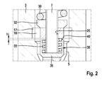
- the spring plate 36 the in FIG. 2 shown enlarged again, in this case has a sleeve-shaped extension 38 which surrounds the nozzle spring 35 almost completely.
- a stop surface 40 is formed as an annular surface on the side facing the guide plate 17, which has a distance h to the guide plate 17 in the closed state of the fuel injection valve.
- the coupler piston 22 is guided in a receptacle 24, which is formed substantially sleeve-shaped and which together with the coupler piston 22 delimits a coupler space 25, which forms a coupling throttle 28 formed within the coupler piston 28 with the control chamber 19th connected is.
- the receptacle 24 is fixedly disposed within the pressure chamber 5, while the coupler piston 22 via a control piston 27 is movable in the longitudinal direction, wherein the control piston 27 in turn is longitudinally movable by an electric actuator, for example by a piezoelectric actuator.
- an electric actuator for example by a piezoelectric actuator.
- a gap remains, through which the fuel can flow in the direction of the injection openings 11.
- grooves or other recesses may be formed on the outside of the receptacle 24, through which a fuel flow past the receptacle is made possible.
- the operation of the fuel injection valve is as follows: At the beginning of the injection, the nozzle needle 7 is in contact with the body seat 8 and thus closes the injection openings 11 with respect to the pressure chamber 5.
- the coupler piston 22 is in its upper position, d. H. with a maximum distance to the nozzle needle 7, wherein the coupler space 25 and the control chamber 19, fed via throttle gaps, as formed for example between the sleeve 15 and the nozzle needle 7 or between the receptacle 24 and the coupler piston 22, are filled with fuel under high pressure with which the pressure chamber 5 is filled.
- the coupler piston 22, driven by the control piston 27, is pressed in the direction of the nozzle needle 7.
- the fuel which exits through the injection openings 11, flows through the high-pressure passage 16 into the pressure chamber 5, through the holes 18 within the guide plate 17 and between the gap, which remains between the spring plate 36 and the wall of the pressure chamber 5, to the injection openings 11.
- the control piston 27 is withdrawn, so that the coupler piston 22 follows this movement and the total volume consisting of the control chamber 19 and the coupler piston 25, again reduced and thus increase the pressure, so that the nozzle needle 7 by the fuel pressure is pressed back into its closed position within the control chamber 19 again.
- the fuel which exits through the injection openings 11 flows - as already mentioned - through the pressure chamber 5 and the bores 18 within the guide plate 17 therethrough. Since the sleeve-shaped extension 38 of the spring plate 36 the Nozzle spring 35 shields radially outward, the fuel does not flow past the nozzle spring 35 and does not affect this in their movement, so that a precisely defined force is exerted on the nozzle needle 7 by the nozzle spring 35.
- a plurality of holes 18 are arranged distributed over the circumference, on the one hand to allow a uniform flow of fuel in the direction of the injection openings 11, which exerts no lateral forces on the nozzle needle 7, and the holes 18 on the other hand ensure that there is no Throttling of the fuel flow and thus a pressure drop at the guide plate 17 comes.
Landscapes
- Engineering & Computer Science (AREA)
- Chemical & Material Sciences (AREA)
- Combustion & Propulsion (AREA)
- Mechanical Engineering (AREA)
- General Engineering & Computer Science (AREA)
- Physics & Mathematics (AREA)
- Electromagnetism (AREA)
- Fuel-Injection Apparatus (AREA)
Applications Claiming Priority (1)
| Application Number | Priority Date | Filing Date | Title |
|---|---|---|---|
| DE102014212337.2A DE102014212337A1 (de) | 2014-06-26 | 2014-06-26 | Kraftstoffeinspritzventil für Brennkraftmaschinen |
Publications (2)
| Publication Number | Publication Date |
|---|---|
| EP2960487A1 true EP2960487A1 (fr) | 2015-12-30 |
| EP2960487B1 EP2960487B1 (fr) | 2020-07-08 |
Family
ID=53051745
Family Applications (1)
| Application Number | Title | Priority Date | Filing Date |
|---|---|---|---|
| EP15166910.8A Not-in-force EP2960487B1 (fr) | 2014-06-26 | 2015-05-08 | Soupape d'injection de carburant pour moteurs à combustion interne |
Country Status (2)
| Country | Link |
|---|---|
| EP (1) | EP2960487B1 (fr) |
| DE (1) | DE102014212337A1 (fr) |
Cited By (1)
| Publication number | Priority date | Publication date | Assignee | Title |
|---|---|---|---|---|
| JP2018204561A (ja) * | 2017-06-06 | 2018-12-27 | 株式会社Soken | 燃料噴射装置、制御装置及び燃料噴射システム |
Citations (7)
| Publication number | Priority date | Publication date | Assignee | Title |
|---|---|---|---|---|
| GB785411A (en) * | 1955-02-23 | 1957-10-30 | Saurer Ag Adolph | Improvements in and relating to injection nozzles for internal combustion engines |
| JPH01157268U (fr) * | 1988-04-21 | 1989-10-30 | ||
| GB2312926A (en) * | 1996-05-09 | 1997-11-12 | Bosch Gmbh Robert | I.c. engine fuel-injection valve with outwardly opening valve member and damping of the opening stroke |
| DE10024703A1 (de) | 2000-05-18 | 2001-11-22 | Bosch Gmbh Robert | Einspritzanordnung für ein Kraftstoff-Speichereinspritzsystem einer Verbrennungsmaschine |
| DE102012205696A1 (de) | 2012-04-05 | 2013-10-10 | Robert Bosch Gmbh | Kraftstoffinjektor, insbesondere Common-Rail-Injektor |
| WO2013178338A1 (fr) * | 2012-05-30 | 2013-12-05 | L'orange Gmbh | Injecteur |
| EP2735725A1 (fr) * | 2012-11-27 | 2014-05-28 | Robert Bosch Gmbh | Soupape d'injection de carburant pour moteurs à combustion interne |
-
2014
- 2014-06-26 DE DE102014212337.2A patent/DE102014212337A1/de not_active Withdrawn
-
2015
- 2015-05-08 EP EP15166910.8A patent/EP2960487B1/fr not_active Not-in-force
Patent Citations (7)
| Publication number | Priority date | Publication date | Assignee | Title |
|---|---|---|---|---|
| GB785411A (en) * | 1955-02-23 | 1957-10-30 | Saurer Ag Adolph | Improvements in and relating to injection nozzles for internal combustion engines |
| JPH01157268U (fr) * | 1988-04-21 | 1989-10-30 | ||
| GB2312926A (en) * | 1996-05-09 | 1997-11-12 | Bosch Gmbh Robert | I.c. engine fuel-injection valve with outwardly opening valve member and damping of the opening stroke |
| DE10024703A1 (de) | 2000-05-18 | 2001-11-22 | Bosch Gmbh Robert | Einspritzanordnung für ein Kraftstoff-Speichereinspritzsystem einer Verbrennungsmaschine |
| DE102012205696A1 (de) | 2012-04-05 | 2013-10-10 | Robert Bosch Gmbh | Kraftstoffinjektor, insbesondere Common-Rail-Injektor |
| WO2013178338A1 (fr) * | 2012-05-30 | 2013-12-05 | L'orange Gmbh | Injecteur |
| EP2735725A1 (fr) * | 2012-11-27 | 2014-05-28 | Robert Bosch Gmbh | Soupape d'injection de carburant pour moteurs à combustion interne |
Cited By (1)
| Publication number | Priority date | Publication date | Assignee | Title |
|---|---|---|---|---|
| JP2018204561A (ja) * | 2017-06-06 | 2018-12-27 | 株式会社Soken | 燃料噴射装置、制御装置及び燃料噴射システム |
Also Published As
| Publication number | Publication date |
|---|---|
| DE102014212337A1 (de) | 2015-12-31 |
| EP2960487B1 (fr) | 2020-07-08 |
Similar Documents
| Publication | Publication Date | Title |
|---|---|---|
| EP2183476B1 (fr) | Soupape d'injection de carburant avec une étanchéité améliorée au niveau du siège d'étanchéité d'une soupape de commande à pression compensée | |
| EP2171258B1 (fr) | Soupape de commande pour une soupape d'injection de carburant | |
| DE19817320C1 (de) | Einspritzventil für Kraftstoffeinspritzsysteme | |
| WO2005019637A1 (fr) | Soupape d'injection de carburant commandee par une soupape pilote | |
| EP3535486B1 (fr) | Soupape d'injection de carburant pour injecter un carburant gazeux et / ou liquide | |
| EP2875232A1 (fr) | Injecteur piézo-électrique dont le mouvement de l'aiguille d'injection est couplé hydrauliquement | |
| DE202014010759U1 (de) | Elektronischer Kraftstoff-Einspritz-Zerstäuber für ein Kraftstoff-Einspritzsystem für einen Verbrennungsmotor | |
| EP2735725A1 (fr) | Soupape d'injection de carburant pour moteurs à combustion interne | |
| EP2960487B1 (fr) | Soupape d'injection de carburant pour moteurs à combustion interne | |
| EP2426348B1 (fr) | Soupape d'injection de combustible | |
| EP2458194B1 (fr) | Soupape d'injection de carburant pour moteurs à combustion interne | |
| WO2017194260A1 (fr) | Injecteur de carburant pour moteurs à combustion interne | |
| WO2011042296A1 (fr) | Soupape d'injection de carburant et sa fabrication | |
| EP2824310B1 (fr) | Soupape d'injection de carburant pour moteurs à combustion interne | |
| DE10312586A1 (de) | Kraftstoffeinspritzventil für Brennkraftmaschinen | |
| EP3791057B1 (fr) | Ensemble formant soupape servant à réguler la pression de gaz dans une rampe de distribution de gaz | |
| WO2005045233A1 (fr) | Soupape d'injection de carburant pour moteur a combustion interne | |
| EP1999363A1 (fr) | SOUPAPES D'INJECTION DE CARBURANT POUR moteurs A COMBUSTION INTERNE | |
| DE10121340A1 (de) | Common-Rail-Injektor | |
| DE102010043110A1 (de) | Kraftstoffeinspritzventil für Brennkraftmaschinen | |
| DE102004051756A1 (de) | Kraftstoffeinspritzventil für Brennkraftmaschinen | |
| DE102005041667B4 (de) | Injektor mit direkter Nadelsteuerung | |
| WO2005026525A1 (fr) | Soupape d'injection de carburant pour moteur a combustion interne | |
| DE102012213535A1 (de) | Kraftstoffinjektor | |
| DE102006008647A1 (de) | Kraftstoffinjektor mit direktbetätigbarer Düsennadel und variabler Aktorhubübersetzung |
Legal Events
| Date | Code | Title | Description |
|---|---|---|---|
| PUAI | Public reference made under article 153(3) epc to a published international application that has entered the european phase |
Free format text: ORIGINAL CODE: 0009012 |
|
| AK | Designated contracting states |
Kind code of ref document: A1 Designated state(s): AL AT BE BG CH CY CZ DE DK EE ES FI FR GB GR HR HU IE IS IT LI LT LU LV MC MK MT NL NO PL PT RO RS SE SI SK SM TR |
|
| AX | Request for extension of the european patent |
Extension state: BA ME |
|
| 17P | Request for examination filed |
Effective date: 20160630 |
|
| RBV | Designated contracting states (corrected) |
Designated state(s): AL AT BE BG CH CY CZ DE DK EE ES FI FR GB GR HR HU IE IS IT LI LT LU LV MC MK MT NL NO PL PT RO RS SE SI SK SM TR |
|
| STAA | Information on the status of an ep patent application or granted ep patent |
Free format text: STATUS: EXAMINATION IS IN PROGRESS |
|
| 17Q | First examination report despatched |
Effective date: 20180905 |
|
| GRAP | Despatch of communication of intention to grant a patent |
Free format text: ORIGINAL CODE: EPIDOSNIGR1 |
|
| STAA | Information on the status of an ep patent application or granted ep patent |
Free format text: STATUS: GRANT OF PATENT IS INTENDED |
|
| INTG | Intention to grant announced |
Effective date: 20191203 |
|
| GRAS | Grant fee paid |
Free format text: ORIGINAL CODE: EPIDOSNIGR3 |
|
| RAP1 | Party data changed (applicant data changed or rights of an application transferred) |
Owner name: ROBERT BOSCH GMBH |
|
| GRAA | (expected) grant |
Free format text: ORIGINAL CODE: 0009210 |
|
| STAA | Information on the status of an ep patent application or granted ep patent |
Free format text: STATUS: THE PATENT HAS BEEN GRANTED |
|
| AK | Designated contracting states |
Kind code of ref document: B1 Designated state(s): AL AT BE BG CH CY CZ DE DK EE ES FI FR GB GR HR HU IE IS IT LI LT LU LV MC MK MT NL NO PL PT RO RS SE SI SK SM TR |
|
| REG | Reference to a national code |
Ref country code: CH Ref legal event code: EP Ref country code: AT Ref legal event code: REF Ref document number: 1288732 Country of ref document: AT Kind code of ref document: T Effective date: 20200715 |
|
| REG | Reference to a national code |
Ref country code: DE Ref legal event code: R096 Ref document number: 502015012937 Country of ref document: DE |
|
| REG | Reference to a national code |
Ref country code: IE Ref legal event code: FG4D Free format text: LANGUAGE OF EP DOCUMENT: GERMAN |
|
| REG | Reference to a national code |
Ref country code: LT Ref legal event code: MG4D |
|
| REG | Reference to a national code |
Ref country code: NL Ref legal event code: MP Effective date: 20200708 |
|
| PG25 | Lapsed in a contracting state [announced via postgrant information from national office to epo] |
Ref country code: FI Free format text: LAPSE BECAUSE OF FAILURE TO SUBMIT A TRANSLATION OF THE DESCRIPTION OR TO PAY THE FEE WITHIN THE PRESCRIBED TIME-LIMIT Effective date: 20200708 Ref country code: LT Free format text: LAPSE BECAUSE OF FAILURE TO SUBMIT A TRANSLATION OF THE DESCRIPTION OR TO PAY THE FEE WITHIN THE PRESCRIBED TIME-LIMIT Effective date: 20200708 Ref country code: PT Free format text: LAPSE BECAUSE OF FAILURE TO SUBMIT A TRANSLATION OF THE DESCRIPTION OR TO PAY THE FEE WITHIN THE PRESCRIBED TIME-LIMIT Effective date: 20201109 Ref country code: NO Free format text: LAPSE BECAUSE OF FAILURE TO SUBMIT A TRANSLATION OF THE DESCRIPTION OR TO PAY THE FEE WITHIN THE PRESCRIBED TIME-LIMIT Effective date: 20201008 Ref country code: SE Free format text: LAPSE BECAUSE OF FAILURE TO SUBMIT A TRANSLATION OF THE DESCRIPTION OR TO PAY THE FEE WITHIN THE PRESCRIBED TIME-LIMIT Effective date: 20200708 Ref country code: BG Free format text: LAPSE BECAUSE OF FAILURE TO SUBMIT A TRANSLATION OF THE DESCRIPTION OR TO PAY THE FEE WITHIN THE PRESCRIBED TIME-LIMIT Effective date: 20201008 Ref country code: ES Free format text: LAPSE BECAUSE OF FAILURE TO SUBMIT A TRANSLATION OF THE DESCRIPTION OR TO PAY THE FEE WITHIN THE PRESCRIBED TIME-LIMIT Effective date: 20200708 Ref country code: GR Free format text: LAPSE BECAUSE OF FAILURE TO SUBMIT A TRANSLATION OF THE DESCRIPTION OR TO PAY THE FEE WITHIN THE PRESCRIBED TIME-LIMIT Effective date: 20201009 Ref country code: HR Free format text: LAPSE BECAUSE OF FAILURE TO SUBMIT A TRANSLATION OF THE DESCRIPTION OR TO PAY THE FEE WITHIN THE PRESCRIBED TIME-LIMIT Effective date: 20200708 |
|
| PG25 | Lapsed in a contracting state [announced via postgrant information from national office to epo] |
Ref country code: PL Free format text: LAPSE BECAUSE OF FAILURE TO SUBMIT A TRANSLATION OF THE DESCRIPTION OR TO PAY THE FEE WITHIN THE PRESCRIBED TIME-LIMIT Effective date: 20200708 Ref country code: RS Free format text: LAPSE BECAUSE OF FAILURE TO SUBMIT A TRANSLATION OF THE DESCRIPTION OR TO PAY THE FEE WITHIN THE PRESCRIBED TIME-LIMIT Effective date: 20200708 Ref country code: LV Free format text: LAPSE BECAUSE OF FAILURE TO SUBMIT A TRANSLATION OF THE DESCRIPTION OR TO PAY THE FEE WITHIN THE PRESCRIBED TIME-LIMIT Effective date: 20200708 Ref country code: IS Free format text: LAPSE BECAUSE OF FAILURE TO SUBMIT A TRANSLATION OF THE DESCRIPTION OR TO PAY THE FEE WITHIN THE PRESCRIBED TIME-LIMIT Effective date: 20201108 |
|
| PG25 | Lapsed in a contracting state [announced via postgrant information from national office to epo] |
Ref country code: NL Free format text: LAPSE BECAUSE OF FAILURE TO SUBMIT A TRANSLATION OF THE DESCRIPTION OR TO PAY THE FEE WITHIN THE PRESCRIBED TIME-LIMIT Effective date: 20200708 |
|
| REG | Reference to a national code |
Ref country code: DE Ref legal event code: R097 Ref document number: 502015012937 Country of ref document: DE |
|
| PG25 | Lapsed in a contracting state [announced via postgrant information from national office to epo] |
Ref country code: CZ Free format text: LAPSE BECAUSE OF FAILURE TO SUBMIT A TRANSLATION OF THE DESCRIPTION OR TO PAY THE FEE WITHIN THE PRESCRIBED TIME-LIMIT Effective date: 20200708 Ref country code: DK Free format text: LAPSE BECAUSE OF FAILURE TO SUBMIT A TRANSLATION OF THE DESCRIPTION OR TO PAY THE FEE WITHIN THE PRESCRIBED TIME-LIMIT Effective date: 20200708 Ref country code: IT Free format text: LAPSE BECAUSE OF FAILURE TO SUBMIT A TRANSLATION OF THE DESCRIPTION OR TO PAY THE FEE WITHIN THE PRESCRIBED TIME-LIMIT Effective date: 20200708 Ref country code: EE Free format text: LAPSE BECAUSE OF FAILURE TO SUBMIT A TRANSLATION OF THE DESCRIPTION OR TO PAY THE FEE WITHIN THE PRESCRIBED TIME-LIMIT Effective date: 20200708 Ref country code: RO Free format text: LAPSE BECAUSE OF FAILURE TO SUBMIT A TRANSLATION OF THE DESCRIPTION OR TO PAY THE FEE WITHIN THE PRESCRIBED TIME-LIMIT Effective date: 20200708 Ref country code: SM Free format text: LAPSE BECAUSE OF FAILURE TO SUBMIT A TRANSLATION OF THE DESCRIPTION OR TO PAY THE FEE WITHIN THE PRESCRIBED TIME-LIMIT Effective date: 20200708 |
|
| PLBE | No opposition filed within time limit |
Free format text: ORIGINAL CODE: 0009261 |
|
| STAA | Information on the status of an ep patent application or granted ep patent |
Free format text: STATUS: NO OPPOSITION FILED WITHIN TIME LIMIT |
|
| PG25 | Lapsed in a contracting state [announced via postgrant information from national office to epo] |
Ref country code: AL Free format text: LAPSE BECAUSE OF FAILURE TO SUBMIT A TRANSLATION OF THE DESCRIPTION OR TO PAY THE FEE WITHIN THE PRESCRIBED TIME-LIMIT Effective date: 20200708 |
|
| 26N | No opposition filed |
Effective date: 20210409 |
|
| PG25 | Lapsed in a contracting state [announced via postgrant information from national office to epo] |
Ref country code: SK Free format text: LAPSE BECAUSE OF FAILURE TO SUBMIT A TRANSLATION OF THE DESCRIPTION OR TO PAY THE FEE WITHIN THE PRESCRIBED TIME-LIMIT Effective date: 20200708 |
|
| PG25 | Lapsed in a contracting state [announced via postgrant information from national office to epo] |
Ref country code: SI Free format text: LAPSE BECAUSE OF FAILURE TO SUBMIT A TRANSLATION OF THE DESCRIPTION OR TO PAY THE FEE WITHIN THE PRESCRIBED TIME-LIMIT Effective date: 20200708 |
|
| REG | Reference to a national code |
Ref country code: CH Ref legal event code: PL |
|
| GBPC | Gb: european patent ceased through non-payment of renewal fee |
Effective date: 20210508 |
|
| PG25 | Lapsed in a contracting state [announced via postgrant information from national office to epo] |
Ref country code: CH Free format text: LAPSE BECAUSE OF NON-PAYMENT OF DUE FEES Effective date: 20210531 Ref country code: MC Free format text: LAPSE BECAUSE OF FAILURE TO SUBMIT A TRANSLATION OF THE DESCRIPTION OR TO PAY THE FEE WITHIN THE PRESCRIBED TIME-LIMIT Effective date: 20200708 Ref country code: LU Free format text: LAPSE BECAUSE OF NON-PAYMENT OF DUE FEES Effective date: 20210508 Ref country code: LI Free format text: LAPSE BECAUSE OF NON-PAYMENT OF DUE FEES Effective date: 20210531 |
|
| REG | Reference to a national code |
Ref country code: BE Ref legal event code: MM Effective date: 20210531 |
|
| PG25 | Lapsed in a contracting state [announced via postgrant information from national office to epo] |
Ref country code: IE Free format text: LAPSE BECAUSE OF NON-PAYMENT OF DUE FEES Effective date: 20210508 Ref country code: GB Free format text: LAPSE BECAUSE OF NON-PAYMENT OF DUE FEES Effective date: 20210508 |
|
| PG25 | Lapsed in a contracting state [announced via postgrant information from national office to epo] |
Ref country code: FR Free format text: LAPSE BECAUSE OF NON-PAYMENT OF DUE FEES Effective date: 20210531 |
|
| REG | Reference to a national code |
Ref country code: AT Ref legal event code: MM01 Ref document number: 1288732 Country of ref document: AT Kind code of ref document: T Effective date: 20210508 |
|
| PG25 | Lapsed in a contracting state [announced via postgrant information from national office to epo] |
Ref country code: BE Free format text: LAPSE BECAUSE OF NON-PAYMENT OF DUE FEES Effective date: 20210531 |
|
| PG25 | Lapsed in a contracting state [announced via postgrant information from national office to epo] |
Ref country code: AT Free format text: LAPSE BECAUSE OF NON-PAYMENT OF DUE FEES Effective date: 20210508 |
|
| PGFP | Annual fee paid to national office [announced via postgrant information from national office to epo] |
Ref country code: DE Payment date: 20220725 Year of fee payment: 8 |
|
| PG25 | Lapsed in a contracting state [announced via postgrant information from national office to epo] |
Ref country code: HU Free format text: LAPSE BECAUSE OF FAILURE TO SUBMIT A TRANSLATION OF THE DESCRIPTION OR TO PAY THE FEE WITHIN THE PRESCRIBED TIME-LIMIT; INVALID AB INITIO Effective date: 20150508 |
|
| PG25 | Lapsed in a contracting state [announced via postgrant information from national office to epo] |
Ref country code: CY Free format text: LAPSE BECAUSE OF FAILURE TO SUBMIT A TRANSLATION OF THE DESCRIPTION OR TO PAY THE FEE WITHIN THE PRESCRIBED TIME-LIMIT Effective date: 20200708 |
|
| REG | Reference to a national code |
Ref country code: DE Ref legal event code: R119 Ref document number: 502015012937 Country of ref document: DE |
|
| PG25 | Lapsed in a contracting state [announced via postgrant information from national office to epo] |
Ref country code: MK Free format text: LAPSE BECAUSE OF FAILURE TO SUBMIT A TRANSLATION OF THE DESCRIPTION OR TO PAY THE FEE WITHIN THE PRESCRIBED TIME-LIMIT Effective date: 20200708 Ref country code: DE Free format text: LAPSE BECAUSE OF NON-PAYMENT OF DUE FEES Effective date: 20231201 |
|
| PG25 | Lapsed in a contracting state [announced via postgrant information from national office to epo] |
Ref country code: MT Free format text: LAPSE BECAUSE OF FAILURE TO SUBMIT A TRANSLATION OF THE DESCRIPTION OR TO PAY THE FEE WITHIN THE PRESCRIBED TIME-LIMIT Effective date: 20200708 |
|
| PG25 | Lapsed in a contracting state [announced via postgrant information from national office to epo] |
Ref country code: TR Free format text: LAPSE BECAUSE OF FAILURE TO SUBMIT A TRANSLATION OF THE DESCRIPTION OR TO PAY THE FEE WITHIN THE PRESCRIBED TIME-LIMIT Effective date: 20200708 |