EP2964971B1 - Dispositif d'amortissement de vibration - Google Patents
Dispositif d'amortissement de vibration Download PDFInfo
- Publication number
- EP2964971B1 EP2964971B1 EP14760064.7A EP14760064A EP2964971B1 EP 2964971 B1 EP2964971 B1 EP 2964971B1 EP 14760064 A EP14760064 A EP 14760064A EP 2964971 B1 EP2964971 B1 EP 2964971B1
- Authority
- EP
- European Patent Office
- Prior art keywords
- inerter
- cam
- hub
- moveable
- valve member
- Prior art date
- Legal status (The legal status is an assumption and is not a legal conclusion. Google has not performed a legal analysis and makes no representation as to the accuracy of the status listed.)
- Active
Links
Images






Classifications
-
- F—MECHANICAL ENGINEERING; LIGHTING; HEATING; WEAPONS; BLASTING
- F16—ENGINEERING ELEMENTS AND UNITS; GENERAL MEASURES FOR PRODUCING AND MAINTAINING EFFECTIVE FUNCTIONING OF MACHINES OR INSTALLATIONS; THERMAL INSULATION IN GENERAL
- F16F—SPRINGS; SHOCK-ABSORBERS; MEANS FOR DAMPING VIBRATION
- F16F15/00—Suppression of vibrations in systems; Means or arrangements for avoiding or reducing out-of-balance forces, e.g. due to motion
- F16F15/10—Suppression of vibrations in rotating systems by making use of members moving with the system
- F16F15/14—Suppression of vibrations in rotating systems by making use of members moving with the system using masses freely rotating with the system, i.e. uninvolved in transmitting driveline torque, e.g. rotative dynamic dampers
-
- F—MECHANICAL ENGINEERING; LIGHTING; HEATING; WEAPONS; BLASTING
- F16—ENGINEERING ELEMENTS AND UNITS; GENERAL MEASURES FOR PRODUCING AND MAINTAINING EFFECTIVE FUNCTIONING OF MACHINES OR INSTALLATIONS; THERMAL INSULATION IN GENERAL
- F16K—VALVES; TAPS; COCKS; ACTUATING-FLOATS; DEVICES FOR VENTING OR AERATING
- F16K1/00—Lift valves or globe valves, i.e. cut-off apparatus with closure members having at least a component of their opening and closing motion perpendicular to the closing faces
- F16K1/12—Lift valves or globe valves, i.e. cut-off apparatus with closure members having at least a component of their opening and closing motion perpendicular to the closing faces with streamlined valve member around which the fluid flows when the valve is opened
- F16K1/126—Lift valves or globe valves, i.e. cut-off apparatus with closure members having at least a component of their opening and closing motion perpendicular to the closing faces with streamlined valve member around which the fluid flows when the valve is opened actuated by fluid
-
- F—MECHANICAL ENGINEERING; LIGHTING; HEATING; WEAPONS; BLASTING
- F16—ENGINEERING ELEMENTS AND UNITS; GENERAL MEASURES FOR PRODUCING AND MAINTAINING EFFECTIVE FUNCTIONING OF MACHINES OR INSTALLATIONS; THERMAL INSULATION IN GENERAL
- F16K—VALVES; TAPS; COCKS; ACTUATING-FLOATS; DEVICES FOR VENTING OR AERATING
- F16K1/00—Lift valves or globe valves, i.e. cut-off apparatus with closure members having at least a component of their opening and closing motion perpendicular to the closing faces
- F16K1/32—Details
-
- F—MECHANICAL ENGINEERING; LIGHTING; HEATING; WEAPONS; BLASTING
- F16—ENGINEERING ELEMENTS AND UNITS; GENERAL MEASURES FOR PRODUCING AND MAINTAINING EFFECTIVE FUNCTIONING OF MACHINES OR INSTALLATIONS; THERMAL INSULATION IN GENERAL
- F16K—VALVES; TAPS; COCKS; ACTUATING-FLOATS; DEVICES FOR VENTING OR AERATING
- F16K17/00—Safety valves; Equalising valves, e.g. pressure relief valves
- F16K17/02—Safety valves; Equalising valves, e.g. pressure relief valves opening on surplus pressure on one side; closing on insufficient pressure on one side
- F16K17/04—Safety valves; Equalising valves, e.g. pressure relief valves opening on surplus pressure on one side; closing on insufficient pressure on one side spring-loaded
- F16K17/0433—Safety valves; Equalising valves, e.g. pressure relief valves opening on surplus pressure on one side; closing on insufficient pressure on one side spring-loaded with vibration preventing means
-
- F—MECHANICAL ENGINEERING; LIGHTING; HEATING; WEAPONS; BLASTING
- F16—ENGINEERING ELEMENTS AND UNITS; GENERAL MEASURES FOR PRODUCING AND MAINTAINING EFFECTIVE FUNCTIONING OF MACHINES OR INSTALLATIONS; THERMAL INSULATION IN GENERAL
- F16K—VALVES; TAPS; COCKS; ACTUATING-FLOATS; DEVICES FOR VENTING OR AERATING
- F16K31/00—Actuating devices; Operating means; Releasing devices
- F16K31/44—Mechanical actuating means
- F16K31/52—Mechanical actuating means with crank, eccentric, or cam
- F16K31/524—Mechanical actuating means with crank, eccentric, or cam with a cam
- F16K31/52408—Mechanical actuating means with crank, eccentric, or cam with a cam comprising a lift valve
- F16K31/52433—Mechanical actuating means with crank, eccentric, or cam with a cam comprising a lift valve with a streamlined or helically shaped valve member, e.g. for reducing flow losses or guiding the fluid flow
-
- F—MECHANICAL ENGINEERING; LIGHTING; HEATING; WEAPONS; BLASTING
- F16—ENGINEERING ELEMENTS AND UNITS; GENERAL MEASURES FOR PRODUCING AND MAINTAINING EFFECTIVE FUNCTIONING OF MACHINES OR INSTALLATIONS; THERMAL INSULATION IN GENERAL
- F16K—VALVES; TAPS; COCKS; ACTUATING-FLOATS; DEVICES FOR VENTING OR AERATING
- F16K47/00—Means in valves for absorbing fluid energy
-
- F—MECHANICAL ENGINEERING; LIGHTING; HEATING; WEAPONS; BLASTING
- F16—ENGINEERING ELEMENTS AND UNITS; GENERAL MEASURES FOR PRODUCING AND MAINTAINING EFFECTIVE FUNCTIONING OF MACHINES OR INSTALLATIONS; THERMAL INSULATION IN GENERAL
- F16K—VALVES; TAPS; COCKS; ACTUATING-FLOATS; DEVICES FOR VENTING OR AERATING
- F16K47/00—Means in valves for absorbing fluid energy
- F16K47/04—Means in valves for absorbing fluid energy for decreasing pressure or noise level, the throttle being incorporated in the closure member
-
- Y—GENERAL TAGGING OF NEW TECHNOLOGICAL DEVELOPMENTS; GENERAL TAGGING OF CROSS-SECTIONAL TECHNOLOGIES SPANNING OVER SEVERAL SECTIONS OF THE IPC; TECHNICAL SUBJECTS COVERED BY FORMER USPC CROSS-REFERENCE ART COLLECTIONS [XRACs] AND DIGESTS
- Y10—TECHNICAL SUBJECTS COVERED BY FORMER USPC
- Y10T—TECHNICAL SUBJECTS COVERED BY FORMER US CLASSIFICATION
- Y10T137/00—Fluid handling
- Y10T137/7722—Line condition change responsive valves
- Y10T137/7781—With separate connected fluid reactor surface
- Y10T137/7793—With opening bias [e.g., pressure regulator]
-
- Y—GENERAL TAGGING OF NEW TECHNOLOGICAL DEVELOPMENTS; GENERAL TAGGING OF CROSS-SECTIONAL TECHNOLOGIES SPANNING OVER SEVERAL SECTIONS OF THE IPC; TECHNICAL SUBJECTS COVERED BY FORMER USPC CROSS-REFERENCE ART COLLECTIONS [XRACs] AND DIGESTS
- Y10—TECHNICAL SUBJECTS COVERED BY FORMER USPC
- Y10T—TECHNICAL SUBJECTS COVERED BY FORMER US CLASSIFICATION
- Y10T137/00—Fluid handling
- Y10T137/7722—Line condition change responsive valves
- Y10T137/7837—Direct response valves [i.e., check valve type]
- Y10T137/7904—Reciprocating valves
-
- Y—GENERAL TAGGING OF NEW TECHNOLOGICAL DEVELOPMENTS; GENERAL TAGGING OF CROSS-SECTIONAL TECHNOLOGIES SPANNING OVER SEVERAL SECTIONS OF THE IPC; TECHNICAL SUBJECTS COVERED BY FORMER USPC CROSS-REFERENCE ART COLLECTIONS [XRACs] AND DIGESTS
- Y10—TECHNICAL SUBJECTS COVERED BY FORMER USPC
- Y10T—TECHNICAL SUBJECTS COVERED BY FORMER US CLASSIFICATION
- Y10T74/00—Machine element or mechanism
- Y10T74/18—Mechanical movements
- Y10T74/18568—Reciprocating or oscillating to or from alternating rotary
- Y10T74/1876—Reciprocating or oscillating to or from alternating rotary including inertia device
Definitions
- the invention relates generally to devices for controlling linear vibration by converting linear motion to rotary motion.
- the invention relates to devices for controlling vibrations in valves (e.g., pressure relief valves).
- valves e.g., pressure relief valves.
- US 3,845,781 discloses a back flow check valve assembly that is subjected to a pulsating flow of compressed fluid when open is constructed to compound lineal inertia with a rotational inertia at low friction with ball bearings in curvilinear raceways to lower its natural response frequency below that of the pulsating flow.
- the effect of the pulsations on the valve is further dampened by minimized turbulence and a fullness of the valve opening against a comparatively light closing spring which with the weight and construction of the valve closes the valve securely during idle time.
- US 1,273,445 discloses a device to prevent chattering in valves and the like.
- the device has a member constructed to have an automatic reciprocatory operative movement in a right-line direction, and means to give the member a positive supplemental movement in a direction at an angle to and simultaneously with each operative right-line movement thereof to prevent a pulsating action of the member.
- the invention provides a vibration damping system as defined in claim 1.
- the moveable element is slidably received in the fixed element, or the movable element slides relative to the fixed element in response to a predetermined pressure, or the moveable element is moveable between a first position and a second position and the vibration damping system further includes a biasing element biasing the moveable element toward the first position, or the inerter element rotates in response to linear movement of the moveable element.
- a vibration damping system that includes a fixed element defining a cam profile, and a floating element coupled to the fixed element and movable relative to the fixed element between a first position and a second position.
- the cam profile converts linear motion of the floating element into rotational movement of the floating element to provide inertial damping.
- the floating element is movable in response to a non-mechanical force, or the floating element moves linearly along an axis between the first position and the second position, and rotates about the axis in response to linear motion, or the cam profile is helical, or the mass of the floating element and the rotational motion provide an inertial damping effect.
- a vibration damping system that includes a fixed element, a floating element coupled to the fixed element for linear motion along an axis and constrained such that rotation of the floating element is inhibited, and an inerter element coupled to the fixed element for rotary movement about the axis and constrained such that the inerter element does not move linearly relative to the floating element.
- the inerter element rotates in response to linear movement of the floating element to convert linear energy to rotary energy.
- the fixed element defines a constraining slot and the floating element includes a constraining pin received in the constraining slot, the interaction of the constraining pin and the constraining slot inhibiting rotation of the floating element relative to the fixed element, or the inerter element defines a cam profile and the floating element engages the cam profile such that linear movement of the floating element forces the inerter element to rotate along the cam profile, or the cam profile is helical, or the mass of the inerter element and the rotational motion thereof provide an inertial damping effect or
- the floating element is moveable in response to a non-mechanical force.
- a valve in another non-claimed aspect, there is provided a valve that includes a housing defining an inlet, an outlet, and a valve seat between the inlet and the outlet, a valve member arranged at least partially within the housing and movable between an open position where flow is provided from the inlet through the valve seat to the outlet, and a closed position where flow is inhibited through the valve seat, and an inerter element arranged to convert linear motion of the valve member into rotary movement, thereby damping the valve.
- the valve further includes a biasing element that biases the valve member toward the closed position, or the valve member moves linearly between the open position and the closed position, the linear motion of the valve member converted by the inerter element into rotary movement of the valve member, the mass and rotational movement of the valve member providing inertial damping, or the inerter element is fixed to the housing, or the valve member moves linearly between the open position and the closed position, or the inerter element rotates in response to the linear movement of the valve member, the mass and rotational movement of the inerter element providing inertial damping, or the valve member is coupled to the housing such that rotary movement of the valve member is inhibited, or the inerter element defines a cam profile, the valve member engaging the cam profile, or the cam profile is helical, or the valve member is biased toward the open position by a pressure, or the valve member actuates in response to a non-mechanical force.
- a biasing element that biases the valve member toward the closed position, or the valve member moves linearly between
- a valve that includes a housing defining an inlet, an outlet, and a valve seat between the inlet and the outlet, a valve member arranged at least partially within the housing and movable between an open position where flow is provided from the inlet through the valve seat to the outlet, and a closed position where flow is inhibited through the valve seat, the valve member coupled to the housing for linear and rotary movement relative to the housing about an axis, and an inerter element substantially fixed to the housing and defining a cam profile, a portion of the valve member engaging the cam profile such that in response to a non-mechanical force the valve member moves between the open position and the closed position and linear motion of the valve member is converted to rotary motion of the valve member, thereby damping the valve.
- the cam profile is helical, or the valve member includes a pin that engages the cam profile, or the valve member is biased toward the closed position, or the valve member is coupled to the inerter element such that the inerter element supports the valve member for linear motion along the axis and rotation about the axis.
- a valve that includes a housing defining an inlet, an outlet, and a valve seat between the inlet and the outlet, a valve member arranged at least partially within the housing and movable between an open position where flow is provided from the inlet through the valve seat to the outlet, and a closed position where flow is inhibited through the valve seat, the valve member coupled to the housing for linear movement relative to the housing along an axis and constrained such that the valve member does not rotate about the axis, and an inerter element coupled to the valve member and defining a cam profile, the inerter element arranged to rotate along the cam profile relative to the valve member about the axis in response to linear movement of the valve member.
- the cam profile is helical, or the valve member includes a pin that engages the cam profile, or the valve member is biased toward the closed position, or the valve member supports the inerter element for rotation about the axis.
- a pressure relief valve that includes a housing defining an inlet, an outlet, and a valve seat between the inlet and the outlet, a bonnet coupled to the housing and including a controller, an inerter system coupled between the housing and the bonnet and including an inerter hub fixed to the housing to inhibit substantial rotation and linear movement, the inerter hub defining a cam profile, and a valve member received by the inerter hub and moveable between an open position where flow is provided from the inlet through the valve seat to the outlet, and a closed position where flow is inhibited through the valve seat, a portion of the valve member engaging the cam profile.
- the controller biases the valve member toward the closed position.
- the valve member moves toward the open position when a predetermined pressure is achieved within the inlet, and linear movement of the valve member between the open position and the closed position causes rotation of the valve member along the cam profile to provide inertial damping.
- the cam profile is a slot formed in the inerter hub
- the valve member includes a pin that engages the slot
- the cam profile is helical
- the valve member moves linearly and rotates about an axis
- the controller is an adjustable spring
- the valve member includes a disk holder arranged to receive a disk for sealing against the valve seat, and a central shaft that is received by the inerter hub, the central shaft extending through the inerter hub, or the valve member is coupled to the inerter hub by a bearing element.
- a pressure relief valve that includes a housing defining an inlet, an outlet, and a valve seat between the inlet and the outlet, a bonnet coupled to the housing and including a controller, an inerter system coupled between the housing and the bonnet and including an inerter hub fixed to the housing to inhibit substantial rotation and linear movement of the inerter hub relative to the housing, a valve member received by the inerter hub and moveable between an open position where flow is provided from the inlet through the valve seat to the outlet, and a closed position where flow is inhibited through the valve seat, the valve member arranged to move linearly relative to the inerter hub and constrained such that rotation of the valve member is inhibited, and a flywheel defining a cam profile and arranged to rotate relative to the valve member.
- the controller biases the valve member toward the closed position.
- the valve member moves toward the open position when a predetermined pressure is achieved within the inlet, and linear movement of the valve member between the open position and the closed position causes rotation of the flywheel along the cam profile to provide inertial damping.
- the pressure relief valve also includes a bellows arranged to inhibit fluid communication between the housing and the bonnet, or linear movement of the flywheel is inhibited, or the cam profile is helical, or the valve member includes a pin that engages the cam profile, or valve member includes a constraining pin and the inerter hub defines a constraining slot, the constraining pin engaging the constraining slot to inhibit rotation of the valve member.
- a pressure relief valve that includes a housing defining an inlet, an outlet, and a valve seat between the inlet and the outlet, a bonnet coupled to the housing and including a controller, an inerter system is coupled between the housing and the bonnet and includes an inerter hub coupled to the housing such that rotation and linear movement of the inerter hub is inhibited, a cam element coupled to the inerter hub and defining a cam profile, a valve member received by the inerter hub and moveable between an open position where flow is provided from the inlet through the valve seat to the outlet, and a closed position where flow is inhibited through the valve seat, and a cam follower coupled between the cam element and the valve member and movable with the valve member.
- the controller biases the valve member toward the closed position.
- the valve member moves toward the open position when a predetermined pressure is achieved within the inlet, and linear movement of the valve member between the open position and the closed position causes rotation of the valve member and the cam follower along the cam profile to provide inertial damping.
- the pressure relief valve also includes a jerk absorber arranged between the inerter hub and the cam element, or the cam follower includes a pin that engages the cam profile and guides the movement of the valve member along the cam profile, or the valve member is arranged for linear movement and rotation about an axis, and the pin is positioned off-center with respect to the axis, or the cam follower element is fixed to the valve member to inhibit substantial rotation and linear movement with respect to the valve member, or the cam element is threaded into the inerter hub, or the cam profile is helical.
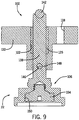
- Section I describes a pressure relief valve that includes a first non-claimed construction with respect to Figs. 1-10 .
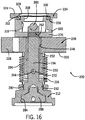
- Section II describes a pressure relief valve including a first construction of the invention with respect to Figs. 11-16 .
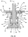
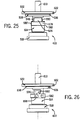
- Section III describes a pressure relief valve including a second construction of the invention with respect to Figs. 17-26 .
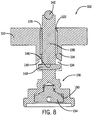
- Section IV includes a discussion of the invention in a broader sense as it relates to other valves types and other modes in which the invention can be used to attenuate and dampen vibrations.
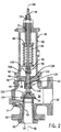
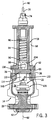
- Figs. 1-3 show a pressure relief valve (hereinafter "PRV") 10 according to one non-claimed construction.
- the PRV 10 serves to relieve pressure formed in a piping system, pressure vessel or associated component (hereinafter “pressure vessel system”).
- pressure vessel system pressure vessel system
- the PRV 10 includes a housing 14, a bonnet 18, and an inerter system 22.
- the housing 14 defines an inlet flange 26 for coupling to the pressure vessel system, a flanged outlet port 30, an interior surface or chamber 34 between the inlet flange 26 and the outlet port 30, and bonnet flange 36 defining a shoulder 38 rimming an opening 40 adjacent an upper portion (as shown in Fig. 2 ) of the chamber 34.
- a nozzle 42 is received within the inlet flange 26 and defines a shaped nozzle profile 46 between a nozzle inlet 50 and a valve seat in the form of a nozzle outlet 54.
- the bonnet 18 includes a bonnet housing 58 that defines a housing flange 62 arranged for coupling to the bonnet flange 36 of the housing 14 and defining a shoulder 66.
- the bonnet housing 58 also defines an adjustment screw aperture 70 sized to threadingly receive an adjustment screw 74.
- a spindle 78 is slidingly received within the adjustment screw 74 and extends along a central axis 82.
- An upper spring washer 86 is positioned adjacent the adjustable screw 74 and slidingly receives the spindle 78.
- a lower spring washer 90 is positioned distally from the upper spring washer 86 with a spring 94 arranged therebetween.
- a spindle bracket 98 is pinned to a lower end (as shown in Fig.
- the adjustable screw 74 can be threaded into and out of the bonnet housing 58 to increase and decrease the biasing force applied by the spring 94.
- the inerter system 22 includes an inerter hub 102 and a valve member in the form of a disk holder 106.
- the inerter hub 102 defines a hub flange 110 and a hub body 114.
- a vent 118 is defined in the hub flange 110 and a central hub bore 122 extends through the inerter hub 102 along the central axis 82.
- a bearing in the form of a bushing 126 is received within the central hub bore 122.
- the hub body 114 defines a first slot 130 and a second slot 134.
- the first slot 130 and second slot 134 together define a cam profile.
- the slots 130, 134 provide a generally helical cam profile.
- the disk holder 106 includes a central shaft 138 that holds at a first end a bearing in the form of a spherical crystal bearing 142 and defines a pin aperture 146.
- a substantially cylindrical pin 148 is fixedly received within the pin aperture 146.
- the disk holder 106 also includes a disk recess 150 arranged to receive a disk 154.
- the inerter system 22 is inserted into the bonnet flange 36 of the housing 14 such that the hub flange 110 is received on the shoulder 38.
- the bonnet 18 is installed onto the housing 14 and the inerter system 22 with the shoulder 66 of the housing flange 62 engaging the hub flange 110.
- the bonnet flange 36 is then fastened to the housing flange 62 with the hub flange 110 fixed therebetween such that the joint is substantially hermetically sealed and the inerter hub 102 is rotationally fixed relative to the housing 14.
- the vent 118 provides fluid communication between the chamber 34 and the bonnet 18 such that no substantial pressure differential exists therebetween.
- the spindle bracket 98 engages the spherical bearing 142 and the spring 94 biases the disk holder 106 downward (as shown in Fig. 2 ) toward a closed position.
- the bias force is adjusted by manipulation of the adjustable screw 74 according to the predetermined specifications of the greater system in which the PRV 10 is installed (e.g., the pressure vessel system).
- the disk holder 106 is arranged such that the pin 148 is received in the first slot 130 and the second slot 134 and the central shaft 138 is guided vertically by the bushing 126 for linear movement along the central axis 82.
- the disk 154 is arranged such that in the closed position (as shown in Fig. 2 ), the disk 154 engages the nozzle outlet 54 to inhibit fluid flow therethrough.
- the slots 130, 134 guide the pin 148 along the cam profile.
- the configuration of the slots 130, 134 determines the ratio of conversion of linear motion to rotational motion.
- the conversion ratio for helically shaped slots having a long lead angle (i.e., more travel distance per one revolution) and a small helix angle is relatively small.
- the conversion ratio for slots having a short lead angle (i.e., less travel distance per one revolution) and a large helix angle is greater.
- the conversion ratio is approximately 9-10 inches of linear motion per one revolution of the disc holder 106.
- Other cam profiles are contemplated and would be used, as determined by one skilled in the art.
- the disc holder 106 rotates in response to linear motion caused by vibration, and thus, is sensitive to acceleration and more effective in reducing or controlling vibration than passive damping techniques.
- the mass of the disk holder 106 itself acts as the flywheel in the inerter system 22.
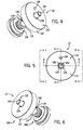
- Figs. 11-16 show an inerter system 200 that can be used with the housing 14 and bonnet 18 shown in Figs. 1-3 in place of the inerter system 22.
- the bonnet housing 58 also defines a cap shoulder 204.
- the inerter system 200 includes an inerter hub 208, a disk holder 212, a bellows 216, a flywheel 220, and a cap 224.
- the inerter hub 208 defines a hub flange 228 and a hub body 232.
- a bearing raceway 236 is defined in the hub flange 228.
- the bearing raceway 236 is a substantially semi-circular and annular raceway. Alternate arrangements are conceivable, such as a raceway arranged for pin bearings, etc.
- a first motion constraining slot 240 and a second motion constraining slot 244 are formed in the hub body 232.
- the motion constraining slots 240, 244 are parallel and substantially vertically oriented (as shown in Fig. 14 ).
- a central hub bore 248 is defined and extends through the inerter hub 208 along the central axis 82.
- a bearing in the form of a bushing 252 is received within the central hub bore 248.
- the disk holder 212 includes a central shaft 256 that holds at a first end a bearing in the form of a spherical crystal bearing 260 and defines a motion constraining pin aperture 264 and a flywheel pin aperture 268.
- a substantially cylindrical motion constraining pin 272 is fixedly received within the motion constraining pin aperture 264 and a substantially cylindrical flywheel pin 276 is fixedly received within the flywheel pin aperture 268.
- the disk holder 212 also defines a bellows mating feature in the form of threads 280 and a disk recess 284 sized to receive a disk 288.
- the bellows 216 includes a mating feature in the form of threads 292 arranged to sealingly mate with the threads 280 of the disk holder 212.
- the bellows 216 further include a expandable body portion 296 arranged to accommodate vertical motion (as shown in Fig. 14 ) of the disk holder 212 and a gasket portion 300 arranged to mate with a bottom surface of the hub flange 228.
- the flywheel 220 defines an annular ring that includes a bottom surface 304, an upper aperture 308, an upper bearing raceway 312, a first cam slot 316, and a second cam slot 320.
- the bottom surface 304 defines a bearing raceway and can define a different shape intended to function optimally with different bearing types than are illustrated herein.
- the first cam slot 316 and second cam slot 320 together define a cam profile.
- the slots 316, 320 provide a generally helical and linear cam profile.
- the cap 224 defines an upper surface 324, an inner aperture 328, and a bearing raceway 332.
- the illustrated bearing raceway 332 is a shoulder recess. In other arrangements, the bearing raceway 332 can be arranged differently.
- the raceway 332 can be arranged to receive pin bearings, or can include a contoured surface (e.g., semi-circular depression, rectangular recess, etc.).
- the inerter system 200 is assembled by installing the bellows 216 onto the disk holder 212 by threading the bellows threads 292 onto the disk holder threads 280 such that a seal is formed therebetween.
- the disk holder 212 and bellows 216 are then installed on the inerter hub 208 by sliding the central shaft 256 into the bushing 252 and positioning the disk holder 212 such that the motion constraining pin 272 is received within the motion constraining slots 240, 244.
- the motion of the disk holder 212 is then constrained by the slots 240, 244 to substantially only vertical movement (as shown in Fig. 14 ) and substantial rotation is inhibited.
- a bearing element in the form of a plurality of ball bearings 336 is arranged in the bearing raceway 236 of the inerter hub 208, and the flywheel 220 installed onto the inerter system 200 by engaging the first cam slot 316 and the second cam slot 320 with the flywheel pin 276, and engaging the bottom surface 304 with the ball bearings 336.
- the bearing raceway 236 of the inerter hub 208 does not extend around the full annulus of the central hub bore 248, but rather inhibits the ball bearings 336 from interfering with the flywheel pin 276 when the disk holder 212 is in the closed position (as shown in Fig. 15 ).
- the bearing raceway 236 can extend fully about the central hub bore 248 and the pin 276 can be arranged differently so no interference exists.
- Another bearing element (in the form of ball bearings 336) is arranged between the upper bearing raceway 312 of the flywheel 220 and the bearing raceway 332 of the cap 224.
- the ball bearings 336 provide smooth rotation of the flywheel 220 under load.
- other bearing elements can be used.
- the ball bearings 336 can be retained within separate raceways, the bearing elements can be pin or needle bearings, conical bearings, or another shape of bearing, as desired.
- the bearing elements can include bushings, or other arrangements designed to provide adequate rotation of the flywheel 220.
- the assembled inerter system 200 is then installed between the housing 14 and the bonnet 18 (see Figs. 2 and 14 ).
- the inerter system 200 is inserted into the housing 14 such that the gasket portion 300 of the bellows 216 engages and seals against the shoulder 38 of the housing 14.
- the shoulder 66 of the bonnet 18 engages the inerter hub 208, and the cap shoulder 204 of the bonnet 18 engages the upper surface 324 of the cap 224.
- the hub flange 228 and the gasket portion 300 are compressed between the shoulder 66 of the bonnet 18 and the shoulder 38 of the housing 14 such that rotation of both components is inhibited.
- the cap 224 is compressed relative to the inerter hub 208 to constrain the flywheel 220.
- the ball bearings 336 provide for rotational movement of the flywheel 220.
- the disk holder 212 is movable between a closed position in which the disk 288 seals against the nozzle outlet 54 to inhibit fluid flow therethrough, and an open position in which the disk disengages from the nozzle outlet 54 to permit fluid flow through the nozzle 42 and out the outlet port 30. Movement of the disk holder 212 is constrained by the central shaft 256 and the motion constraining pin 272 such that the disk holder 212 moves only in the vertical direction (as shown in Fig. 14 ) between the open position and the closed position with substantially no rotational movement.
- the bellows 216 is arranged to compress and expand along with the motion of the disk holder 212 between the open position and the closed position.
- the bellows 216 provides a barrier between the fluid and the other components of the inerter system 200 as can be advantageous in corrosive fluid control or other implementations.
- the flywheel pin 276 engages and moves along the first cam slot 316 and the second cam slot 320 such that the flywheel 220 is forced into rotation by the cam profile defined by the first cam slot 316 and the second cam slot 320.
- the rotation of the flywheel 220 causes inertial damping of the disk holder 212 similarly to the inerter system 22 discussed above in Section I.
- Figs. 17-26 show a PRV 400 according to one embodiment of the invention that includes a housing 414, a bonnet 418, and an inerter system 422.
- the housing 414 defines an inlet flange 426 for coupling to a pressure vessel system, a flanged outlet port 430, an interior surface or chamber 434 between the inlet flange 426 and the outlet port 430, and a bonnet flange 436 defining a housing shoulder 438 rimming an opening adjacent an upper portion 440 (as shown in Fig. 18 ) of the chamber 434.
- a nozzle 442 is received within the inlet flange 426 and defines a shaped nozzle profile 446 between a nozzle inlet 450 and a nozzle outlet 454.
- the bonnet 418 includes a bonnet housing 458 that defines a housing flange 462 arranged for coupling to the bonnet flange 436 of the housing 414 and defining a bonnet shoulder 466.
- the bonnet housing 458 also defines an adjustment screw aperture 470 sized to threadingly receive an adjustment screw 474.
- a spindle 478 is slidingly received within the adjustment screw 474 and extends along a central axis 482.
- An upper spring washer 486 is positioned adjacent the adjustable screw 474 and slidingly receives the spindle 478.
- a lower spring washer 490 is positioned distally from the upper spring washer 486 with a spring 494 arranged therebetween.
- a spindle bracket 498 is pinned to a lower end (as shown in Fig.
- the adjustable screw 474 can be threaded into and out of the bonnet housing 458 to increase and decrease the biasing force applied by the spring 494, as desired.
- the inerter system 422 includes an inerter hub 502, a cam element 506, a jerk absorber 510, a cam follower element 514, and a disk holder 518.
- the inerter hub 502 defines a hub flange 522, a hub body 526 extending downward (as shown in Fig. 24 ) from the hub flange 522, and a jerk aperture 530 defined through the hub flange 522.
- the hub body 526 defines hub body threads 532 substantially adjacent the hub flange 522.
- a central aperture 534 is defined through the inerter hub 502 along the central axis 482.
- the central aperture 534 is manufactured such that an inner surface of the central aperture 534 forms a bearing surface.
- the bearing surface can be machined and polished, reamed, or formed in another way to provide a suitable bearing surface.
- a bearing or bushing can be inserted within the central aperture 534.
- the jerk aperture 530 is sized to press fittingly receive the jerk absorber 510.
- the jerk aperture 530 can be threaded, or can be filleted in preparation of a welding procedure.
- Other arrangements are conceivable (e.g., soldering, fastening, gluing, etc.).
- the cam element 506 defines a cam element flange 538, a central aperture 542 that is sized to receive the hub body 526, a first cam 546, and a second cam 550.
- the cam element flange 538 defines a jerk aperture 554.
- the central aperture 542 defines cam element threads 558 sized to loosely engage the hub body threads 532.
- the first cam 546 and the second cam 550 together define a cam profile. In the illustrated embodiment, the cams 546, 550 provide a generally helical cam profile.
- the jerk absorber 510 includes a jerk pin 562 that defines a vent 566 (as shown in Fig. 24 ) and is sized to be press fit into the jerk aperture 530 of the inerter hub 502.
- the jerk absorber 510 also includes a bushing 570 engaged on the jerk pin 562 and received within the jerk aperture 554 of the cam element 506.
- the illustrated bushing 570 is constructed of a shock dissipating material such as rubber, includes a bushing flange 574 arranged to be sandwiched between the hub flange 522 and the cam flange 538, and is snugly received within the jerk aperture 554 of the cam element 506.
- the cam follower element 514 defines a follower flange 578 that includes two flat portions 582, a central aperture 586 sized to receive the cam element 506, and a follower threaded portion 590.
- Each flat portion 582 includes a cam pin aperture 594 sized to receive a cam pin 598.
- the cam pin apertures 594 (and therefore the pins 598) are positioned off-center with respect to the center axis 482 (as shown in Fig. 26 ).
- the cam pins 598 are arranged to engage the first cam 546 and the second cam 550.
- the follower threaded portion 590 includes a threaded aperture 602 sized to receive a set screw 606.
- the disk holder 518 defines a central shaft 610 that holds at a first end a bearing in the form of a spherical crystal bearing 614 (as shown in Fig. 18 ) and defines a disk recess 618 arranged to receive a disk 622.
- the disk holder 518 further includes a holder threaded portion 626 arranged to threadingly receive the follower threaded portion 590, and a set screw aperture 630 arranged to receive the set screw 606.
- the jerk bushing 570 is inserted into the jerk aperture 554 of the cam element 506.
- the cam element 506 is then coupled to the inerter hub 502 by threading the cam element threads 558 onto the hub body threads 532.
- the threads 558, 532 engage loosely such that the cam element 506 spins easily.
- the jerk aperture 530 of the inerter hub 502 is then aligned with the jerk aperture 554 of the cam element 506.
- the jerk pin 562 is press fit into the jerk aperture 530 of the inerter hub 502, and the jerk bushing 570 that is positioned in the jerk aperture 554 of the cam element 506.
- the threaded portion 590 of the cam follower element 514 is then threaded onto the threaded portion 626 of the disk holder 518, and the set screw 606 is tightened such that the cam follower element 514 is substantially rigidly coupled to the disk holder 518.
- the disk holder 518 and the cam follower element 514 are then slid onto the cam element 506 such that the pins 598 are engaged with the first cam 546 and the second cam 550.
- the hub flange 522 is engaged with the shoulder 438 of the housing 414 such that the disk 622 engages the nozzle outlet 454.
- the bonnet 418 is then installed with the shoulder 466 of the bonnet flange 462 engaging the hub flange 522 and the spindle bracket 498 engaging the spherical bearing 614.
- the bonnet 418 is then fastened to the housing 414 such that the inerter hub 502 is fixed in place and inhibited from rotational and linear movement.
- the disk holder 518 is moveable between an open position where fluid is permitted to flow from the nozzle inlet 450 through the nozzle outlet 454, and out of the outlet port 430, and a closed position where the disk 622 engages the nozzle outlet 454 and inhibits fluid flow therethrough.
- the PRV 400 is typically in the closed position, and when pressure acting on the disk holder 518 overcomes the bias force of the spring 494, the disk holder 518 moves toward the open position. Moving toward the open position, the pins 598 engage the first cam 546 and the second cam 550 and move the disk holder 518 along the cam profile. This results in a translation of linear motion to rotational work and has an inertial damping effect on the system, as discussed above.
- the jerk absorber 510 functions to absorb the initial shock and impact that the inerter system 422 undergoes upon the pressure in the pressure vessel or any downstream vibration overcoming the bias force of the spring 494.
- the jerk bushing 570 absorbs the impact and the threaded portions 532, 558 interact to allow a slight rotation of the cam element 506 relative to the inerter hub 502.
- PRVs form an undamped linear spring mass mechanism and are configured to enable pressure control over narrow pressure ranges.
- Resonant acoustic frequencies due to inlet pipe and/or other periodic inlet pipe dynamics cause an undesirable rapid cycling motion or vibration in the PRVs, sometimes known as "chatter," wherein the disc rapidly cycles between the open and closed positions.
- Such vibration reduces the capacity of the PRV and can cause damage to internal components such as the disc and valve seat (i.e., nozzle outlet).
- Attempts have been made to reduce the effects of such vibration by modifying disc face, seat, and nozzle geometries in order to enhance the stability of PRVs. This method is effective at enhancing stability at relatively low pressures but has limited effectiveness in enhancing stability at relatively high pressures.
- Embodiments of the invention provide, among other things, an inerter system wherein linear motion along a center axis is converted to rotational motion about the center axis. This conversion has the effect of adding inertial damping to the PRV.
- the inerter system reacts to acceleration of the system, as opposed to the more traditional passive systems that react to velocity. In other words, the invention has a much faster reaction and provides better damping with significantly less movement of the disc holder away form the nozzle outlet.
- the magnitude of the inertial damping effect provided by the inerter system is at least in part controlled by a cam profile defined by the structure of the inerter system (e.g., slots 130, 134, 316, 320 and cams 546, 550).
- the cam profile can have a constant or variable lead, a curved shape, a variable shape, a straight shape that is angled relative to the center axis, a shape in accordance with a square or cube root function or a combination of such shapes, and other suitable shapes.
- the cam profile is helically shaped.
- the cam profile can include at least one stepped portion that is located between first and second curved portions, for example.
- the disc holder initially rotates in a first portion of the cam profile, dwells, then resumes rotation in a second portion of the cam profile.
- the cam profile has a right hand lead, resulting in a corresponding rotation direction.
- the cam profile can be positioned in an angled orientation relative to the center axis that is opposite than that depicted in the figures.
- the cam profile can have a left hand lead.
- Embodiments of the invention control vibration in a PRV without adding significant mass to the disc holder when compared with a typical disk holder.
- existing PRVs can be retrofitted in the field with the invention without extensive modification.
- the invention can be used in conjunction with other types of valves.
- the invention can also be used in any suitable valve configuration having a component or components, such as a valve stem that includes a disc or other components, which move in a linear motion and which are susceptible to an undesirable rapid cycling motion due to dynamic instability or vibration.
- the invention can be applied to various types of line valves, check valves, relief valves, or other valves that are subject to vibrations and pressure fluctuations.
- 15-20% of the energy produced by vertical movement is converted to rotary energy in the damping process. In other embodiments, more or less energy can be converted, depending on the desired characteristics of the damping system. For example, 10-50% or more of the vertical energy can be converted to rotary energy by the inerter system. As discussed above, the cam profile can be manipulated to produce the desired damping characteristics.
- Another advantage offered by embodiments of the invention is the ability to produce damped valves that are functional as single fluid valves. That is to say, a single valve design can be used for both a gas product and a liquid product.
- Current passively damped valves are not suitable for single fluid arrangement, because they are not capable of damping the systems to stability in the presence of the variety of conditions that are posed by a liquid product versus a gas product, or vice versa.
- the present invention recognizes the problem of damping and chatter issues as a lack of non-active systems that dampen in response to acceleration of a vibration and provide a wide ranging mode for dealing with such vibrations.
- the concept of a floating input e.g., disk holder, etc. is one that reacts to non-mechanical force such as pressure. That is to say, the floating input is not coupled between two fixed mechanical points for damping vibrations formed therebetween.
- a floating input is not connected to a linkage (e.g., automobile suspension), not directly moved by a contact force (e.g., physical impact by an object), or rigidly coupled at its extremities.
- valves are direct spring operated
- the invention is capable with working with suitable actuation systems, including but not limited to, pilot operation, solenoid operation, and other control mechanisms.
Landscapes
- Engineering & Computer Science (AREA)
- General Engineering & Computer Science (AREA)
- Mechanical Engineering (AREA)
- Physics & Mathematics (AREA)
- Fluid Mechanics (AREA)
- Acoustics & Sound (AREA)
- Aviation & Aerospace Engineering (AREA)
- Safety Valves (AREA)
- Vibration Prevention Devices (AREA)
- Transmission Devices (AREA)
Claims (5)
- Système d'amortissement de vibration (200), comprenant:un élément fixe (208);un élément mobile (212) qui est agencé de manière à se déplacer de façon linéaire le long d'un axe par rapport à l'élément fixe en réponse à une force non mécanique; etun élément d'inertie (220) qui relie l'élément mobile à l'élément fixe, et qui est configuré de manière à convertir le mouvement linéaire de l'élément mobile en un mouvement de rotation autour de l'axe,caractérisé en ce quel'élément d'inertie définit une fente (316, 320) qui présente un profil de came hélicoïdal, et l'élément mobile comporte une saillie (276) qui est reçue dans la fente de telle sorte qu'un déplacement linéaire de l'élément mobile soit converti en un mouvement de rotation le long du profil de came; et en ce quel'élément mobile est empêché de tourner, et le profil de came entraîne l'élément d'inertie à tourner autour de l'axe.
- Système d'amortissement de vibration selon la revendication 1, dans lequel:(i) l'élément mobile est reçu de façon coulissante dans l'élément fixe; ou(ii) l'élément mobile coulisse par rapport à l'élément fixe en réponse à une pression prédéterminée; ou(iii) l'élément mobile est déplaçable entre une première position et une seconde position, etcomprenant en outre un élément de poussée qui pousse l'élément mobile en direction de la première position.
- Système d'amortissement de vibration selon la revendication 1, dans lequel l'élément d'inertie tourne en réponse à un déplacement linéaire de l'élément mobile.
- Système d'amortissement de vibration selon la revendication 1, dans lequel la masse de l'élément mobile et le mouvement de rotation génèrent un effet d'amortissement inertiel.
- Système d'amortissement de vibration selon la revendication 1, dans lequel l'élément fixe définit une fente de contrainte (244), et
dans lequel l'élément mobile comprend une broche de contrainte (272) qui est reçue dans la fente de contrainte (240, 244), l'interaction de la broche de contrainte et de la fente de contrainte empêchant la rotation de l'élément mobile par rapport à l'élément fixe.
Applications Claiming Priority (5)
| Application Number | Priority Date | Filing Date | Title |
|---|---|---|---|
| US201361773458P | 2013-03-06 | 2013-03-06 | |
| US14/198,345 US9200726B2 (en) | 2013-03-06 | 2014-03-05 | Vibration damping device |
| US14/198,373 US9103466B2 (en) | 2013-03-06 | 2014-03-05 | Vibration damping device |
| US14/198,401 US9103467B2 (en) | 2013-03-06 | 2014-03-05 | Vibration damping device for a valve |
| PCT/US2014/021316 WO2014138438A1 (fr) | 2013-03-06 | 2014-03-06 | Dispositif d'amortissement de vibration |
Publications (4)
| Publication Number | Publication Date |
|---|---|
| EP2964971A1 EP2964971A1 (fr) | 2016-01-13 |
| EP2964971A4 EP2964971A4 (fr) | 2016-11-09 |
| EP2964971B1 true EP2964971B1 (fr) | 2018-06-06 |
| EP2964971B8 EP2964971B8 (fr) | 2018-07-18 |
Family
ID=51486335
Family Applications (1)
| Application Number | Title | Priority Date | Filing Date |
|---|---|---|---|
| EP14760064.7A Active EP2964971B8 (fr) | 2013-03-06 | 2014-03-06 | Dispositif d'amortissement de vibration |
Country Status (7)
| Country | Link |
|---|---|
| US (5) | US9200726B2 (fr) |
| EP (1) | EP2964971B8 (fr) |
| KR (1) | KR102013562B1 (fr) |
| AU (1) | AU2014225650B2 (fr) |
| BR (1) | BR112015021943A2 (fr) |
| CA (1) | CA2904050C (fr) |
| WO (1) | WO2014138438A1 (fr) |
Families Citing this family (14)
| Publication number | Priority date | Publication date | Assignee | Title |
|---|---|---|---|---|
| JP6472637B2 (ja) * | 2014-10-30 | 2019-02-20 | 株式会社鷺宮製作所 | 電動弁 |
| US10145434B2 (en) * | 2016-05-19 | 2018-12-04 | The Boeing Company | Translational inerter assembly and method for damping movement of a flight control surface |
| US10088006B2 (en) * | 2016-05-19 | 2018-10-02 | The Boeing Company | Rotational inerter and method for damping an actuator |
| US10107347B2 (en) * | 2016-05-19 | 2018-10-23 | The Boeing Company | Dual rack and pinion rotational inerter system and method for damping movement of a flight control surface of an aircraft |
| CN106004302B (zh) * | 2016-06-29 | 2018-04-06 | 广西大学 | Isd一体化悬架 |
| FR3059748B1 (fr) * | 2016-12-07 | 2019-12-20 | Peugeot Citroen Automobiles Sa | Amortisseur avec amortissement dynamique |
| CN107143602B (zh) * | 2017-04-13 | 2018-10-16 | 安徽奥泰粉末冶金有限公司 | 一种汽车用减震阀座 |
| CN111379872B (zh) | 2018-12-28 | 2021-06-08 | 浙江三花制冷集团有限公司 | 一种流量控制阀 |
| JP7300160B2 (ja) * | 2019-06-28 | 2023-06-29 | 株式会社フジキン | バルブ |
| CN111779867B (zh) * | 2020-08-03 | 2021-12-28 | 浙江东辰阀门科技有限公司 | 一种抑振减压阀 |
| CN112377635B (zh) * | 2020-11-10 | 2022-05-31 | 德清三盛氟塑科技有限公司 | 一种用于食品的卫生阀门 |
| CN114321249B (zh) * | 2022-01-14 | 2022-11-29 | 华南农业大学 | 一种具有惯容效果的三维螺旋单元、机械超材料及其应用 |
| US12504083B2 (en) * | 2023-04-13 | 2025-12-23 | Curtiss-Wright Flow Control Corporation | Relief valve |
| CN117072601A (zh) * | 2023-09-19 | 2023-11-17 | 同济大学 | 一种气体惯容减振装置 |
Family Cites Families (74)
| Publication number | Priority date | Publication date | Assignee | Title |
|---|---|---|---|---|
| US1380737A (en) * | 1921-06-07 | pelletieb | ||
| US1213590A (en) * | 1916-08-18 | 1917-01-23 | Clarence D Compton | Poppet-valve. |
| US1244287A (en) * | 1917-03-23 | 1917-10-23 | Continental Engineering Corp | Valve for internal-combustion engines. |
| US1273445A (en) * | 1917-08-18 | 1918-07-23 | James C Beckerleg | Means to prevent chattering in valves and the like. |
| US1380586A (en) * | 1920-04-03 | 1921-06-07 | Pelletier Products Mfg Co Inc | Valve |
| US1513741A (en) * | 1920-05-25 | 1924-11-04 | Continental Engineering Corp | Valve rotator |
| US1520273A (en) * | 1922-08-19 | 1924-12-23 | Continental Engineering Corp | Rotary valve |
| US2316649A (en) | 1940-04-16 | 1943-04-13 | Albert E Jurs | Relief valve |
| US2576516A (en) | 1947-05-19 | 1951-11-27 | Shand And Jurs Company | Pressure relief valve |
| US2570432A (en) | 1949-03-05 | 1951-10-09 | Watts Regulator Co | Pressure and temperature relief valve |
| US2609803A (en) * | 1949-12-24 | 1952-09-09 | Gen Motors Corp | Valve rotating device |
| US2609804A (en) * | 1949-12-31 | 1952-09-09 | Gen Motors Corp | Valve rotating device |
| US2785861A (en) | 1951-02-21 | 1957-03-19 | Standard Thomson Corp | Tank vent controlling mechanism |
| US2662511A (en) * | 1951-04-10 | 1953-12-15 | Thompson Prod Inc | Automatic mechanical clearance regulator |
| US2792015A (en) | 1953-08-11 | 1957-05-14 | J E Lonergan Company | Liquid relief valve |
| US2815040A (en) | 1954-01-13 | 1957-12-03 | J E Lonergan Company | Pressure relief valve |
| US2810527A (en) | 1954-02-03 | 1957-10-22 | Erich W Work | Temperature and pressure relief valve |
| US2868494A (en) * | 1954-08-26 | 1959-01-13 | United Aircraft Corp | Anti-vibrating solenoid valve |
| US3068848A (en) * | 1960-12-29 | 1962-12-18 | Thompson Ramo Wooldridge Inc | Valve rotating mechanism |
| US3294111A (en) | 1965-06-01 | 1966-12-27 | Us Industries Inc | Relief valve |
| US3386469A (en) | 1966-07-29 | 1968-06-04 | Robertshaw Controls Co | Pressure regulator |
| US3477456A (en) | 1967-04-03 | 1969-11-11 | Anderson Greenwood & Co | Valve |
| US3524470A (en) * | 1967-11-29 | 1970-08-18 | Carl L C Kah Jr | Sequencing valve |
| US3698420A (en) * | 1968-12-05 | 1972-10-17 | Us Navy | Drain valve having auxiliary seal |
| FR1597979A (fr) | 1968-12-20 | 1970-06-29 | ||
| US3585974A (en) * | 1969-02-28 | 1971-06-22 | Robert L Weber | Valve actuating mechanism |
| US3845781A (en) * | 1972-03-22 | 1974-11-05 | Refrigerating Specialties Co | Check valve for pulsating flows |
| US3794062A (en) | 1972-08-17 | 1974-02-26 | J Auwerter | Fluid pressure reducing valve |
| US3881505A (en) | 1974-03-04 | 1975-05-06 | Vapor Corp | Pressure responsive pilot valve |
| DE2605015A1 (de) | 1976-02-10 | 1977-08-11 | Leinemann Co Flammenfilter | Pilotgesteuertes membranventil |
| US4061115A (en) * | 1976-06-01 | 1977-12-06 | Predhome Jr Wilfred F | Valve train for internal combustion engine |
| DE2646535C3 (de) * | 1976-10-15 | 1985-07-18 | Ringspann Albrecht Maurer Kg, 6380 Bad Homburg | Ventildrehvorrichtung für Brennkraftmaschinen |
| US4091837A (en) | 1976-08-02 | 1978-05-30 | Vapor Corporation | Freezeproof breather valve |
| CA1078884A (fr) | 1977-03-16 | 1980-06-03 | Jean Masclet | Methode d'amortissement oleomecanique des chocs et des vibrations sur une charge |
| US4172466A (en) | 1977-07-01 | 1979-10-30 | Target Rock Corporation | Self-actuated pilot-controlled safety valve |
| US4316480A (en) * | 1978-10-30 | 1982-02-23 | Kah Jr Carl L C | Sequencing valve |
| CH655359A5 (de) * | 1980-08-08 | 1986-04-15 | Maerkisches Werk Gmbh | Ventildrehvorrichtung an einer brennkraftmaschine. |
| US4462420A (en) | 1982-06-14 | 1984-07-31 | Teledyne Farris Engineering | Safety pressure relief valve |
| US4460009A (en) * | 1982-09-07 | 1984-07-17 | Ralph A. Hiller Company | Valve stem actuator |
| US4515179A (en) | 1983-01-28 | 1985-05-07 | Vapor Corporation | Pressure relief valve with adjustment for set pressure |
| US4531542A (en) * | 1983-08-22 | 1985-07-30 | Baird Manufacturing Company | Fluid dampened back pressure regulator |
| DE3432465A1 (de) | 1984-09-04 | 1986-03-13 | Boge Gmbh, 5208 Eitorf | Regelbares daempfungsventil fuer einen hydraulischen schwingungsdaempfer |
| US4720087A (en) | 1986-09-05 | 1988-01-19 | Lord Corporation | Inertia type fluid mount using electrorheological and other fluid |
| US5048751A (en) | 1990-04-16 | 1991-09-17 | Outboard Marine Corporation | Pressure and temperature relief valve and diaphragm valve |
| FR2666861B1 (fr) | 1990-09-19 | 1992-10-16 | Alsthom Fluides Sapag | Generateur d'adresses pour la memoire de donnees d'un processeur. |
| US5555910A (en) | 1994-08-30 | 1996-09-17 | Groth Corporation | Pressure relief valves adapted for low pressure operation |
| US5730416A (en) | 1995-06-07 | 1998-03-24 | Welker Engineering Company | Method and apparatus for quieting turbulence in a gas flow line valve |
| US5913330A (en) | 1996-12-19 | 1999-06-22 | Enardo Manufacturing Company | Pressure/vacuum relief valve assembly |
| US6105987A (en) | 1997-12-17 | 2000-08-22 | Rockshox, Inc. | Valve mechanism for damping system |
| US5967165A (en) | 1997-12-19 | 1999-10-19 | Tyco Flow Control, Inc. | Method and apparatus for increasing valve flow efficiency |
| US5992449A (en) | 1998-03-09 | 1999-11-30 | Groth Corporation | Pilot operated safety relief valve adapted for low fluid pressures |
| US6047949A (en) * | 1998-09-21 | 2000-04-11 | Beauchemin, Jr.; George A. | Programmable fluid flow control valve |
| US6352143B1 (en) | 2000-03-09 | 2002-03-05 | Bridgestone/Firestone, Inc. | Vibration damping system using a hydraulic damper with a field responsive fluid control |
| JP4001748B2 (ja) | 2000-05-25 | 2007-10-31 | アスコ・コントロールズ・エル・ピー | 組み込まれたリリーフバルブを有する圧力調整ピストン |
| GB0116424D0 (en) | 2001-07-04 | 2001-08-29 | Univ Cambridge Tech | Mechanical device |
| US6516765B1 (en) * | 2002-02-05 | 2003-02-11 | Caterpillar Inc | Passively rotating valve |
| US20050230201A1 (en) | 2004-04-16 | 2005-10-20 | Takuhiro Kondou | Electromagnetic shock absorber for vehicle |
| JP2004347106A (ja) * | 2003-05-22 | 2004-12-09 | Hyundai Motor Co Ltd | 減衰力可変ショックアブソーバ |
| US7624850B2 (en) | 2005-08-24 | 2009-12-01 | Gm Global Technology Operations, Inc. | Damping device having controllable resistive force |
| US7699146B1 (en) | 2006-04-02 | 2010-04-20 | Fox Factory, Inc. | Suspension damper having inertia valve and user adjustable pressure-relief |
| ITMI20061406A1 (it) | 2006-07-20 | 2008-01-21 | Larix Srl | Valvola di sparo a regolazione fine |
| JP4881803B2 (ja) | 2007-07-03 | 2012-02-22 | 千代田化工建設株式会社 | 安全弁振動解析装置 |
| TW200918783A (en) | 2007-10-26 | 2009-05-01 | Univ Nat Taiwan | Hydraulic-type inerter mechanism |
| SG153002A1 (en) * | 2007-11-16 | 2009-06-29 | Millipore Corp | Fluid transfer device |
| EP2240704B1 (fr) | 2008-02-05 | 2018-08-15 | Cooper-Standard Automotive, Inc. | Ensemble de monture hydraulique amorti axialement |
| EP2246205B1 (fr) | 2008-02-08 | 2014-09-03 | Kayaba Industry Co., Ltd. | Dispositif de suspension |
| JP5086830B2 (ja) | 2008-02-08 | 2012-11-28 | 株式会社キーエンス | 画像検査装置、画像検査方法、及びコンピュータプログラム |
| JP5142810B2 (ja) | 2008-05-09 | 2013-02-13 | カヤバ工業株式会社 | サスペンション装置 |
| EP2187084A1 (fr) | 2008-11-14 | 2010-05-19 | Joseph Talpe | Amortisseur de rotation hydraulique |
| JP5424751B2 (ja) | 2009-07-10 | 2014-02-26 | カヤバ工業株式会社 | サスペンション装置 |
| US8544497B2 (en) * | 2009-10-30 | 2013-10-01 | Emd Millipore Corporation | Fluid transfer device and system |
| US20130032442A1 (en) | 2010-01-25 | 2013-02-07 | Lotus FI Team Limited | Fluid Inerter |
| CN102933868B (zh) | 2010-02-05 | 2015-09-16 | 剑桥企业有限公司 | 用于控制机械力的设备及包括该设备的系统和减震方法 |
| WO2012054774A2 (fr) | 2010-10-20 | 2012-04-26 | Penske Racing Shocks | Absorbeur de choc à inertance |
-
2014
- 2014-03-05 US US14/198,345 patent/US9200726B2/en active Active
- 2014-03-05 US US14/198,401 patent/US9103467B2/en active Active
- 2014-03-05 US US14/198,373 patent/US9103466B2/en active Active
- 2014-03-06 CA CA2904050A patent/CA2904050C/fr active Active
- 2014-03-06 EP EP14760064.7A patent/EP2964971B8/fr active Active
- 2014-03-06 BR BR112015021943A patent/BR112015021943A2/pt not_active IP Right Cessation
- 2014-03-06 AU AU2014225650A patent/AU2014225650B2/en active Active
- 2014-03-06 KR KR1020157027819A patent/KR102013562B1/ko active Active
- 2014-03-06 WO PCT/US2014/021316 patent/WO2014138438A1/fr not_active Ceased
-
2015
- 2015-06-18 US US14/743,785 patent/US20150285331A1/en not_active Abandoned
- 2015-06-18 US US14/743,798 patent/US20150285400A1/en not_active Abandoned
Non-Patent Citations (1)
| Title |
|---|
| None * |
Also Published As
| Publication number | Publication date |
|---|---|
| US9103466B2 (en) | 2015-08-11 |
| KR20150122250A (ko) | 2015-10-30 |
| BR112015021943A2 (pt) | 2017-07-18 |
| US20140251458A1 (en) | 2014-09-11 |
| WO2014138438A1 (fr) | 2014-09-12 |
| US20150285331A1 (en) | 2015-10-08 |
| CA2904050C (fr) | 2019-06-18 |
| AU2014225650B2 (en) | 2017-06-15 |
| US20140251462A1 (en) | 2014-09-11 |
| CA2904050A1 (fr) | 2014-09-12 |
| US20140251457A1 (en) | 2014-09-11 |
| EP2964971A1 (fr) | 2016-01-13 |
| US9103467B2 (en) | 2015-08-11 |
| US9200726B2 (en) | 2015-12-01 |
| KR102013562B1 (ko) | 2019-10-21 |
| EP2964971B8 (fr) | 2018-07-18 |
| US20150285400A1 (en) | 2015-10-08 |
| EP2964971A4 (fr) | 2016-11-09 |
| AU2014225650A1 (en) | 2015-10-29 |
Similar Documents
| Publication | Publication Date | Title |
|---|---|---|
| EP2964971B1 (fr) | Dispositif d'amortissement de vibration | |
| US11131361B2 (en) | Methods and apparatus for position sensitive suspension damping | |
| US9121468B2 (en) | Rotary damper | |
| SE0701971L (sv) | Vingdämpare med justerbar dämpkraft | |
| JPH0333533A (ja) | 回転振動緩衝装置における流体状の緩衝媒体の時間的流量を変化させるための装置 | |
| GB2044882A (en) | Hydraulic shock absorber with vortex valve | |
| KR20170112598A (ko) | 충격 감쇄장치가 구비된 스윙 체크밸브 | |
| JP6151175B2 (ja) | 振動抑制装置 | |
| EP3532745B1 (fr) | Appareil amortisseur de vibrations de siège de ressort destiné à être utilisé avec des régulateurs de pression | |
| AU2006335229A1 (en) | Apparatus for elimination of transient pressure spikes on stiff fluid systems | |
| CN113309897A (zh) | 一种阀芯缓冲结构 | |
| JP6962733B2 (ja) | 防振装置 | |
| JP6546453B2 (ja) | 減衰バルブおよび緩衝器 | |
| JPS6229709Y2 (fr) | ||
| JP7156656B2 (ja) | 調圧弁 | |
| CN109826971A (zh) | 一种电动阀以及具有该电动阀的换热器组件 | |
| JPH06324746A (ja) | 減圧弁のピストン構造 | |
| JPH03134388A (ja) | ウォータハンマ防止装置 | |
| PL41463B1 (fr) |
Legal Events
| Date | Code | Title | Description |
|---|---|---|---|
| PUAI | Public reference made under article 153(3) epc to a published international application that has entered the european phase |
Free format text: ORIGINAL CODE: 0009012 |
|
| 17P | Request for examination filed |
Effective date: 20151005 |
|
| AK | Designated contracting states |
Kind code of ref document: A1 Designated state(s): AL AT BE BG CH CY CZ DE DK EE ES FI FR GB GR HR HU IE IS IT LI LT LU LV MC MK MT NL NO PL PT RO RS SE SI SK SM TR |
|
| AX | Request for extension of the european patent |
Extension state: BA ME |
|
| DAX | Request for extension of the european patent (deleted) | ||
| A4 | Supplementary search report drawn up and despatched |
Effective date: 20161010 |
|
| RIC1 | Information provided on ipc code assigned before grant |
Ipc: F16F 9/12 20060101ALI20161004BHEP Ipc: F16F 9/512 20060101ALI20161004BHEP Ipc: F16D 57/00 20060101AFI20161004BHEP |
|
| STAA | Information on the status of an ep patent application or granted ep patent |
Free format text: STATUS: EXAMINATION IS IN PROGRESS |
|
| 17Q | First examination report despatched |
Effective date: 20170621 |
|
| GRAP | Despatch of communication of intention to grant a patent |
Free format text: ORIGINAL CODE: EPIDOSNIGR1 |
|
| STAA | Information on the status of an ep patent application or granted ep patent |
Free format text: STATUS: GRANT OF PATENT IS INTENDED |
|
| INTG | Intention to grant announced |
Effective date: 20171205 |
|
| RAP1 | Party data changed (applicant data changed or rights of an application transferred) |
Owner name: PENTAIR FLOW CONTROL AG |
|
| GRAJ | Information related to disapproval of communication of intention to grant by the applicant or resumption of examination proceedings by the epo deleted |
Free format text: ORIGINAL CODE: EPIDOSDIGR1 |
|
| STAA | Information on the status of an ep patent application or granted ep patent |
Free format text: STATUS: EXAMINATION IS IN PROGRESS |
|
| GRAR | Information related to intention to grant a patent recorded |
Free format text: ORIGINAL CODE: EPIDOSNIGR71 |
|
| GRAS | Grant fee paid |
Free format text: ORIGINAL CODE: EPIDOSNIGR3 |
|
| STAA | Information on the status of an ep patent application or granted ep patent |
Free format text: STATUS: GRANT OF PATENT IS INTENDED |
|
| GRAA | (expected) grant |
Free format text: ORIGINAL CODE: 0009210 |
|
| STAA | Information on the status of an ep patent application or granted ep patent |
Free format text: STATUS: THE PATENT HAS BEEN GRANTED |
|
| GRAT | Correction requested after decision to grant or after decision to maintain patent in amended form |
Free format text: ORIGINAL CODE: EPIDOSNCDEC |
|
| INTC | Intention to grant announced (deleted) | ||
| INTG | Intention to grant announced |
Effective date: 20180425 |
|
| AK | Designated contracting states |
Kind code of ref document: B1 Designated state(s): AL AT BE BG CH CY CZ DE DK EE ES FI FR GB GR HR HU IE IS IT LI LT LU LV MC MK MT NL NO PL PT RO RS SE SI SK SM TR |
|
| REG | Reference to a national code |
Ref country code: GB Ref legal event code: FG4D |
|
| RAP2 | Party data changed (patent owner data changed or rights of a patent transferred) |
Owner name: EMERSON VULCAN HOLDING LLC |
|
| REG | Reference to a national code |
Ref country code: CH Ref legal event code: EP Ref country code: AT Ref legal event code: REF Ref document number: 1006431 Country of ref document: AT Kind code of ref document: T Effective date: 20180615 |
|
| REG | Reference to a national code |
Ref country code: IE Ref legal event code: FG4D |
|
| REG | Reference to a national code |
Ref country code: DE Ref legal event code: R096 Ref document number: 602014026678 Country of ref document: DE |
|
| REG | Reference to a national code |
Ref country code: DE Ref legal event code: R081 Ref document number: 602014026678 Country of ref document: DE Owner name: EMERSON VULCAN HOLDING LLC, ST. LOUIS, US Free format text: FORMER OWNER: PENTAIR FLOW CONTROL AG, SCHAFFHAUSEN, CH |
|
| REG | Reference to a national code |
Ref country code: BE Ref legal event code: PD Owner name: EMERSON VULCAN HOLDING LLC; US Free format text: DETAILS ASSIGNMENT: CHANGE OF OWNER(S), CESSION; FORMER OWNER NAME: EMERSON VULCAN HOLDING LLC Effective date: 20180814 |
|
| REG | Reference to a national code |
Ref country code: NL Ref legal event code: FP |
|
| REG | Reference to a national code |
Ref country code: LT Ref legal event code: MG4D |
|
| PG25 | Lapsed in a contracting state [announced via postgrant information from national office to epo] |
Ref country code: ES Free format text: LAPSE BECAUSE OF FAILURE TO SUBMIT A TRANSLATION OF THE DESCRIPTION OR TO PAY THE FEE WITHIN THE PRESCRIBED TIME-LIMIT Effective date: 20180606 Ref country code: LT Free format text: LAPSE BECAUSE OF FAILURE TO SUBMIT A TRANSLATION OF THE DESCRIPTION OR TO PAY THE FEE WITHIN THE PRESCRIBED TIME-LIMIT Effective date: 20180606 Ref country code: CY Free format text: LAPSE BECAUSE OF FAILURE TO SUBMIT A TRANSLATION OF THE DESCRIPTION OR TO PAY THE FEE WITHIN THE PRESCRIBED TIME-LIMIT Effective date: 20180606 Ref country code: FI Free format text: LAPSE BECAUSE OF FAILURE TO SUBMIT A TRANSLATION OF THE DESCRIPTION OR TO PAY THE FEE WITHIN THE PRESCRIBED TIME-LIMIT Effective date: 20180606 Ref country code: NO Free format text: LAPSE BECAUSE OF FAILURE TO SUBMIT A TRANSLATION OF THE DESCRIPTION OR TO PAY THE FEE WITHIN THE PRESCRIBED TIME-LIMIT Effective date: 20180906 Ref country code: BG Free format text: LAPSE BECAUSE OF FAILURE TO SUBMIT A TRANSLATION OF THE DESCRIPTION OR TO PAY THE FEE WITHIN THE PRESCRIBED TIME-LIMIT Effective date: 20180906 Ref country code: SE Free format text: LAPSE BECAUSE OF FAILURE TO SUBMIT A TRANSLATION OF THE DESCRIPTION OR TO PAY THE FEE WITHIN THE PRESCRIBED TIME-LIMIT Effective date: 20180606 |
|
| PG25 | Lapsed in a contracting state [announced via postgrant information from national office to epo] |
Ref country code: HR Free format text: LAPSE BECAUSE OF FAILURE TO SUBMIT A TRANSLATION OF THE DESCRIPTION OR TO PAY THE FEE WITHIN THE PRESCRIBED TIME-LIMIT Effective date: 20180606 Ref country code: GR Free format text: LAPSE BECAUSE OF FAILURE TO SUBMIT A TRANSLATION OF THE DESCRIPTION OR TO PAY THE FEE WITHIN THE PRESCRIBED TIME-LIMIT Effective date: 20180907 Ref country code: LV Free format text: LAPSE BECAUSE OF FAILURE TO SUBMIT A TRANSLATION OF THE DESCRIPTION OR TO PAY THE FEE WITHIN THE PRESCRIBED TIME-LIMIT Effective date: 20180606 Ref country code: RS Free format text: LAPSE BECAUSE OF FAILURE TO SUBMIT A TRANSLATION OF THE DESCRIPTION OR TO PAY THE FEE WITHIN THE PRESCRIBED TIME-LIMIT Effective date: 20180606 |
|
| REG | Reference to a national code |
Ref country code: AT Ref legal event code: MK05 Ref document number: 1006431 Country of ref document: AT Kind code of ref document: T Effective date: 20180606 |
|
| PG25 | Lapsed in a contracting state [announced via postgrant information from national office to epo] |
Ref country code: SK Free format text: LAPSE BECAUSE OF FAILURE TO SUBMIT A TRANSLATION OF THE DESCRIPTION OR TO PAY THE FEE WITHIN THE PRESCRIBED TIME-LIMIT Effective date: 20180606 Ref country code: RO Free format text: LAPSE BECAUSE OF FAILURE TO SUBMIT A TRANSLATION OF THE DESCRIPTION OR TO PAY THE FEE WITHIN THE PRESCRIBED TIME-LIMIT Effective date: 20180606 Ref country code: PL Free format text: LAPSE BECAUSE OF FAILURE TO SUBMIT A TRANSLATION OF THE DESCRIPTION OR TO PAY THE FEE WITHIN THE PRESCRIBED TIME-LIMIT Effective date: 20180606 Ref country code: EE Free format text: LAPSE BECAUSE OF FAILURE TO SUBMIT A TRANSLATION OF THE DESCRIPTION OR TO PAY THE FEE WITHIN THE PRESCRIBED TIME-LIMIT Effective date: 20180606 Ref country code: CZ Free format text: LAPSE BECAUSE OF FAILURE TO SUBMIT A TRANSLATION OF THE DESCRIPTION OR TO PAY THE FEE WITHIN THE PRESCRIBED TIME-LIMIT Effective date: 20180606 Ref country code: IS Free format text: LAPSE BECAUSE OF FAILURE TO SUBMIT A TRANSLATION OF THE DESCRIPTION OR TO PAY THE FEE WITHIN THE PRESCRIBED TIME-LIMIT Effective date: 20181006 Ref country code: AT Free format text: LAPSE BECAUSE OF FAILURE TO SUBMIT A TRANSLATION OF THE DESCRIPTION OR TO PAY THE FEE WITHIN THE PRESCRIBED TIME-LIMIT Effective date: 20180606 |
|
| PG25 | Lapsed in a contracting state [announced via postgrant information from national office to epo] |
Ref country code: SM Free format text: LAPSE BECAUSE OF FAILURE TO SUBMIT A TRANSLATION OF THE DESCRIPTION OR TO PAY THE FEE WITHIN THE PRESCRIBED TIME-LIMIT Effective date: 20180606 |
|
| REG | Reference to a national code |
Ref country code: DE Ref legal event code: R097 Ref document number: 602014026678 Country of ref document: DE |
|
| PLBE | No opposition filed within time limit |
Free format text: ORIGINAL CODE: 0009261 |
|
| STAA | Information on the status of an ep patent application or granted ep patent |
Free format text: STATUS: NO OPPOSITION FILED WITHIN TIME LIMIT |
|
| 26N | No opposition filed |
Effective date: 20190307 |
|
| PG25 | Lapsed in a contracting state [announced via postgrant information from national office to epo] |
Ref country code: DK Free format text: LAPSE BECAUSE OF FAILURE TO SUBMIT A TRANSLATION OF THE DESCRIPTION OR TO PAY THE FEE WITHIN THE PRESCRIBED TIME-LIMIT Effective date: 20180606 Ref country code: SI Free format text: LAPSE BECAUSE OF FAILURE TO SUBMIT A TRANSLATION OF THE DESCRIPTION OR TO PAY THE FEE WITHIN THE PRESCRIBED TIME-LIMIT Effective date: 20180606 |
|
| PG25 | Lapsed in a contracting state [announced via postgrant information from national office to epo] |
Ref country code: MC Free format text: LAPSE BECAUSE OF FAILURE TO SUBMIT A TRANSLATION OF THE DESCRIPTION OR TO PAY THE FEE WITHIN THE PRESCRIBED TIME-LIMIT Effective date: 20180606 |
|
| REG | Reference to a national code |
Ref country code: CH Ref legal event code: PL |
|
| PG25 | Lapsed in a contracting state [announced via postgrant information from national office to epo] |
Ref country code: AL Free format text: LAPSE BECAUSE OF FAILURE TO SUBMIT A TRANSLATION OF THE DESCRIPTION OR TO PAY THE FEE WITHIN THE PRESCRIBED TIME-LIMIT Effective date: 20180606 Ref country code: LU Free format text: LAPSE BECAUSE OF NON-PAYMENT OF DUE FEES Effective date: 20190306 |
|
| PG25 | Lapsed in a contracting state [announced via postgrant information from national office to epo] |
Ref country code: IE Free format text: LAPSE BECAUSE OF NON-PAYMENT OF DUE FEES Effective date: 20190306 Ref country code: CH Free format text: LAPSE BECAUSE OF NON-PAYMENT OF DUE FEES Effective date: 20190331 Ref country code: LI Free format text: LAPSE BECAUSE OF NON-PAYMENT OF DUE FEES Effective date: 20190331 |
|
| PG25 | Lapsed in a contracting state [announced via postgrant information from national office to epo] |
Ref country code: TR Free format text: LAPSE BECAUSE OF FAILURE TO SUBMIT A TRANSLATION OF THE DESCRIPTION OR TO PAY THE FEE WITHIN THE PRESCRIBED TIME-LIMIT Effective date: 20180606 |
|
| PG25 | Lapsed in a contracting state [announced via postgrant information from national office to epo] |
Ref country code: PT Free format text: LAPSE BECAUSE OF FAILURE TO SUBMIT A TRANSLATION OF THE DESCRIPTION OR TO PAY THE FEE WITHIN THE PRESCRIBED TIME-LIMIT Effective date: 20181008 Ref country code: MT Free format text: LAPSE BECAUSE OF NON-PAYMENT OF DUE FEES Effective date: 20190306 |
|
| PG25 | Lapsed in a contracting state [announced via postgrant information from national office to epo] |
Ref country code: HU Free format text: LAPSE BECAUSE OF FAILURE TO SUBMIT A TRANSLATION OF THE DESCRIPTION OR TO PAY THE FEE WITHIN THE PRESCRIBED TIME-LIMIT; INVALID AB INITIO Effective date: 20140306 |
|
| PG25 | Lapsed in a contracting state [announced via postgrant information from national office to epo] |
Ref country code: MK Free format text: LAPSE BECAUSE OF FAILURE TO SUBMIT A TRANSLATION OF THE DESCRIPTION OR TO PAY THE FEE WITHIN THE PRESCRIBED TIME-LIMIT Effective date: 20180606 |
|
| P01 | Opt-out of the competence of the unified patent court (upc) registered |
Effective date: 20230602 |
|
| PGFP | Annual fee paid to national office [announced via postgrant information from national office to epo] |
Ref country code: NL Payment date: 20260219 Year of fee payment: 13 |
|
| PGFP | Annual fee paid to national office [announced via postgrant information from national office to epo] |
Ref country code: GB Payment date: 20260220 Year of fee payment: 13 |
|
| PGFP | Annual fee paid to national office [announced via postgrant information from national office to epo] |
Ref country code: DE Payment date: 20260219 Year of fee payment: 13 |
|
| PGFP | Annual fee paid to national office [announced via postgrant information from national office to epo] |
Ref country code: BE Payment date: 20260219 Year of fee payment: 13 Ref country code: IT Payment date: 20260219 Year of fee payment: 13 |
|
| PGFP | Annual fee paid to national office [announced via postgrant information from national office to epo] |
Ref country code: FR Payment date: 20260219 Year of fee payment: 13 |