EP2965957B1 - Schwenkbares verbindungselement für ein scheibenwischerblatt eines fahrzeugs - Google Patents
Schwenkbares verbindungselement für ein scheibenwischerblatt eines fahrzeugs Download PDFInfo
- Publication number
- EP2965957B1 EP2965957B1 EP15174985.0A EP15174985A EP2965957B1 EP 2965957 B1 EP2965957 B1 EP 2965957B1 EP 15174985 A EP15174985 A EP 15174985A EP 2965957 B1 EP2965957 B1 EP 2965957B1
- Authority
- EP
- European Patent Office
- Prior art keywords
- pivot link
- connector
- blade
- substantially cylindrical
- cylindrical shaft
- Prior art date
- Legal status (The legal status is an assumption and is not a legal conclusion. Google has not performed a legal analysis and makes no representation as to the accuracy of the status listed.)
- Not-in-force
Links
- 239000012530 fluid Substances 0.000 claims description 31
- 244000007853 Sarothamnus scoparius Species 0.000 description 8
- 241001631457 Cannula Species 0.000 description 7
- 239000011521 glass Substances 0.000 description 3
- 238000012550 audit Methods 0.000 description 2
- 230000006378 damage Effects 0.000 description 2
- 238000004519 manufacturing process Methods 0.000 description 2
- XLYOFNOQVPJJNP-UHFFFAOYSA-N water Substances O XLYOFNOQVPJJNP-UHFFFAOYSA-N 0.000 description 2
- 238000005452 bending Methods 0.000 description 1
- 230000000295 complement effect Effects 0.000 description 1
- 239000013013 elastic material Substances 0.000 description 1
- 238000005516 engineering process Methods 0.000 description 1
- 235000021183 entrée Nutrition 0.000 description 1
- 238000003780 insertion Methods 0.000 description 1
- 230000037431 insertion Effects 0.000 description 1
- 238000002955 isolation Methods 0.000 description 1
- 230000014759 maintenance of location Effects 0.000 description 1
- 238000000926 separation method Methods 0.000 description 1
- 238000005507 spraying Methods 0.000 description 1
- 238000004804 winding Methods 0.000 description 1
Images

Classifications
-
- B—PERFORMING OPERATIONS; TRANSPORTING
- B60—VEHICLES IN GENERAL
- B60S—SERVICING, CLEANING, REPAIRING, SUPPORTING, LIFTING, OR MANOEUVRING OF VEHICLES, NOT OTHERWISE PROVIDED FOR
- B60S1/00—Cleaning of vehicles
- B60S1/02—Cleaning windscreens, windows or optical devices
- B60S1/04—Wipers or the like, e.g. scrapers
- B60S1/32—Wipers or the like, e.g. scrapers characterised by constructional features of wiper blade arms or blades
- B60S1/40—Connections between blades and arms
- B60S1/4038—Connections between blades and arms for arms provided with a channel-shaped end
- B60S1/4041—Connections between blades and arms for arms provided with a channel-shaped end the channel-shaped end comprising a pivot pin mounted between the side walls
-
- B—PERFORMING OPERATIONS; TRANSPORTING
- B60—VEHICLES IN GENERAL
- B60S—SERVICING, CLEANING, REPAIRING, SUPPORTING, LIFTING, OR MANOEUVRING OF VEHICLES, NOT OTHERWISE PROVIDED FOR
- B60S1/00—Cleaning of vehicles
- B60S1/02—Cleaning windscreens, windows or optical devices
- B60S1/04—Wipers or the like, e.g. scrapers
- B60S1/32—Wipers or the like, e.g. scrapers characterised by constructional features of wiper blade arms or blades
- B60S1/38—Wiper blades
- B60S1/3848—Flat-type wiper blade, i.e. without harness
- B60S1/3849—Connectors therefor; Connection to wiper arm; Attached to blade
- B60S1/3862—Transport of liquid there through
-
- B—PERFORMING OPERATIONS; TRANSPORTING
- B60—VEHICLES IN GENERAL
- B60S—SERVICING, CLEANING, REPAIRING, SUPPORTING, LIFTING, OR MANOEUVRING OF VEHICLES, NOT OTHERWISE PROVIDED FOR
- B60S1/00—Cleaning of vehicles
- B60S1/02—Cleaning windscreens, windows or optical devices
- B60S1/04—Wipers or the like, e.g. scrapers
- B60S1/32—Wipers or the like, e.g. scrapers characterised by constructional features of wiper blade arms or blades
- B60S1/40—Connections between blades and arms
- B60S1/4038—Connections between blades and arms for arms provided with a channel-shaped end
Definitions
- the present invention relates to a pivot connection for a wiper blade of a window, in particular rear, vehicle, for example automobile.
- the present invention furthermore relates to an assembly comprising a mechanical connector and such a pivot connection, an assembly comprising such a pivot connection and a drive arm of a wiper blade of a vehicle window, as well as a wiper blade of a vehicle window.
- a car is conventionally equipped with windshield wipers to ensure that a window is washed and that the driver's vision of the environment is not disturbed.
- These wipers generally comprise a drive arm, performing an angular reciprocating movement, and elongate brushes, themselves carrying wiper blades made of an elastic material. These blades rub against the glass and evacuate the water by bringing it out of the driver's field of vision.
- the brushes are made in the form, or in a conventional version, articulated stirrups that hold the scraper blade in several discrete places by giving it a bend allowing it to marry the eventual curvature of the window, or, in a newer version called "flat blade” (for "flat blade”), a semi-rigid assembly that maintains the wiper blade along its length through one or more bending vertebrae to apply the broom on the glass without having to use stirrups.
- the blade includes a mechanical connector that includes or carries a pivot connection intended to cooperate with the arm or an element carried by the arm to allow the pivoting of the blade vis-à-vis arm, for example to facilitate the replacement of the wiper blade in case of wear.
- a pivot connection for a wiper blade is simply formed by a cylindrical axis, which is generally received in a cylindrical housing of the connector.
- Document EP 2 692 597 A shows a pivot connection for a wiper blade of a vehicle window as described in the preamble of the first claim.
- the present invention proposes an improvement to this technology which makes it possible in particular to simplify the manufacture of a connector for a windscreen wiper blade equipped with fluid projection means, and in particular windshield washer fluid.
- the invention proposes for this purpose a pivot connection for a wiper blade of a vehicle window, in particular an automobile, the pivot connection comprising a substantially cylindrical axis configured to be fixed on a mechanical connector of said blade, characterized in that it comprises fluidic distribution means, and in that it comprises at least one anti-rotation member configured to cooperate with said connector to prevent rotation of the pivot connection vis-à-vis the connector.
- the invention thus proposes equipping the pivot connection with fluid distribution means and thus adding a complementary function (fluid distribution) to the pivot connection.
- the mechanical connector can thus itself be devoid of fluid distribution means, which simplifies its manufacture.
- the pivot connection is made integral in rotation of the connector, so that the fluid distribution means can be easily implanted in the vicinity of this connector to allow distribution to the brush.
- the present invention also relates to an assembly comprising a mechanical connector and a pivot connection as described above, for a wiper blade of a vehicle window, in particular a motor vehicle, the connector comprising means for fixing a wiper blade of said blade or a support member of said wiper blade of said blade.
- the present invention also relates to a wiper blade of a vehicle window, in particular an automobile, comprising a pivot connection or an assembly as described above.
- the present invention finally relates to an assembly comprising a pivot connection as described above and a driving arm of a wiper blade of a vehicle window, in particular an automobile, the arm comprising at least one bracket , and preferably two tabs, the or each lug having a receiving housing, preferably by resilient snapping, and rotation of the substantially cylindrical axis of the pivot connection.
- the longitudinal or lateral names refer to the orientation of the wiper blade according to the invention.
- the longitudinal direction corresponds to the main axis of the blade in which it extends
- the lateral orientations correspond to intersecting straight lines, that is to say which intersect the longitudinal direction, in particular perpendicular to the longitudinal axis of the blade. broom in his plane of rotation.
- the outer or inner names are assessed relative to the axis of rotation of the blade, the inner designation corresponding to the portion of the blade located on the side of this axis of rotation.
- the directions referenced as upper or lower correspond to orientations perpendicular to the plane of rotation of the blade, the lower denomination containing the plane of the window to be wiped.
- FIGS. 1 to 6 illustrate an embodiment of the invention and show a wiper 10 which is particularly suitable but not exclusively for wiping a rear window of a motor vehicle.
- the wiper 10 essentially comprises two elements: a longitudinal broom 12 and a longitudinal arm 14 for driving the broom.
- the arm 14, shown in figures 1 and 6 extends along at least a portion of the broom to cover and protect it. It comprises at one longitudinal end (not visible) means for attachment to a shaft of an electric motor driving the arm, and further comprises means 16 for attaching the blade, which will be described in more detail in the following .
- the blade 12 comprises a longitudinal body 18 carrying a wiper blade 20, at least one and here two stiffening vertebrae 22, a mechanical connector 24 equipped with a pivot connection 26 for connecting the blade 12 to the arm 14, and end caps (not visible).
- the wiper blade 20 is made of rubber and is intended to rub against the window of the vehicle to evacuate the water by bringing it out of the field of view of the driver.
- the body 18 has lateral longitudinal grooves 28 in which the two vertebrae 22 are housed respectively ( Figures 2 and 3 ). These vertebrae 22 are parallel and coplanar and stiffen the wiper blade 20, so as to promote its application on the glass.
- the body 18 and the blade 20 are here made in one piece.
- the body 18 is tubular and has in section a substantially rectangular shape.
- the body 18 comprises two lateral longitudinal walls 32a, 32b substantially parallel and interconnected by two longitudinal walls, respectively upper 33a, and lower 33b, substantially parallel.
- the walls of the body 18 define an internal longitudinal cavity 30 for winding washer fluid. At least one of the side walls 32a of the body is pierced with orifices 34 for the projection of washer fluid 36 on the window to be wiped.
- the upper wall 33a of the body 18 (which has here been cut for clarity) comprises a through hole 38 for mounting fluid distribution means 40, which will be described in more detail in the following.
- These dispensing means 40 provide the washer fluid supply of the cavity 30 of the body 18.
- Each end cap is fitted on a longitudinal end of the body 18 and on the corresponding longitudinal ends of the vertebrae 22, and is intended to hold the latter in the grooves 28 of the body 18.
- the connector 24 essentially comprises two parts: lower means 42 for fastening to the body 18 and upper means 44 for fixing the pivot connection 26.
- the lower fixing means 42 have in cross section a substantially U-shaped inverted and comprise two longitudinal side walls 46 substantially parallel and at a distance from one another and which are interconnected at their upper ends by an upper wall 48
- the side walls 46 are intended to extend on either side of a portion of the body 18 and each comprise a longitudinal groove 50 for receiving a longitudinal end portion of a vertebra 22.
- the insertion of the vertebrae 22 in the grooves 28 of the body 18 and the grooves 50 of the connector 24 ensures the attachment of the connector to the body.
- the upper wall 48 of the connector 24 is substantially flat and extends above the upper wall 33a of the body, substantially parallel thereto. In the mounting position, the walls 48, 33a may be in contact.
- the wall 48 comprises a through orifice 52 which is aligned with the orifice of the body 18 for the passage of the fluid distribution means 40.
- the orifice 52 has a diameter which is greater here than that of the orifice 38.
- the upper fastening means 44 have a substantially U-shaped cross-section and comprise two longitudinal lateral lugs 54 that are substantially parallel and at a distance from one another and which are interconnected at their lower ends by the upper wall 48.
- the lateral lugs 54 are intended to extend on either side of the upper outlet of the orifice 52 of the upper wall 48.
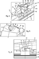
- Each lug 54 comprises a receiving housing 56, here by resilient snapping, of a part of the pivot connection 26 ( figure 5 ).
- Each housing 56 has a generally cylindrical shape.
- the housings 56 are coaxial.
- Each housing 56 opens on a longitudinal edge upper corresponding lug 54 via a radial opening 58 (here flared upwards).
- each housing 56 comprises a notch 60 substantially radial. The notch 60 extends substantially radially and is diametrically opposite to the opening 58.
- P1 denotes the transverse plane, substantially vertical, passing through the middle of the notches 60, housing 56 and openings 58, and passing through the middle of the orifice 52.
- the pivot connection 26 essentially comprises two parts: a substantially cylindrical transverse axis 62 and the aforementioned fluid distribution means 40.
- the shaft 62 is intended to be engaged by resilient snapping in the housing 56 of the connector. It has a length greater than the width or transverse dimension of the upper attachment means 44 of the connector 24 so that the longitudinal end portions of the shaft 62 project from the external lateral faces of the tabs 54 of the connector, as is visible in figure 5 especially.
- Anti-rotation ribs 64 are provided projecting on the axis 62 to cooperate with the notches 60 of the connector.
- the ribs 64 have a longitudinal orientation and extend downwardly from the axis 62. One of their longitudinal ends is connected to the distribution means 40 and the other of their longitudinal ends is free and intended to be engaged in a notch 60.
- the ribs 64 cooperate by abutment with the edges of the notches 60 to prevent any rotation of the axis 62 in the housings 56, and thus any rotation of the pivot connection 26 vis-à-vis the connector 24.
- each rib 64 In mounting position represented in figure 5 the free end of each rib 64 is substantially aligned with the external lateral face of the corresponding lug 54 of the connector 24.
- the fluid distribution means 40 here comprise two cannulas, respectively inlet 66 and outlet 68 of fluid (washer fluid).
- the cannulas 66, 68 are tubular and substantially cylindrical. They each have a rectilinear orientation.
- the axes of the flutes 66, 68 are substantially perpendicular. They are also substantially perpendicular to the axis 62. They extend in a plane P3 passing substantially in the middle of the axis 62.
- the inlet cannula 66 is here substantially horizontal in the mounting position and comprises a longitudinal end connected via the axis 62 to an upper longitudinal end of the outlet cannula 68.
- the longitudinal end portion 66a of the Inlet cannula 66, opposite axis 62, is configured to be nested in one end of a hose and is shaped here to facilitate and maintain this engagement.
- the lower longitudinal end portion 68a of the outlet cannula 68 is configured to pass loosely through the orifice 52 of the connector 24 and to be fitted without play or with a snug fit into the orifice 38 of the body 18 ( figure 4 ).
- the cannulas 66, 68 are here interconnected by a median portion of the axis 62 which comprises an internal passage (not visible) for fluidic connection of the cannulas. In the mounting position, the cannulas 66, 68 extend between the lateral lugs 54 of the connector 24.
- the pivot connection comprising the cannulas 66, 68, the ribs 64 and the axis 62, is here formed in one piece.
- the figures 1 and 6 show the means 16 for fixing and articulation of the arm 14 to the blade 12, and in particular to the pivot connection 26 carried by the blade.
- the arm 14 comprises two lower lateral tabs 70 each having a housing 72 for receiving, here by resilient snapping, a longitudinal end portion of the shaft 62.
- the tabs 70 are substantially parallel and have a substantially longitudinal orientation. They are spaced in the direction transverse to each other by a distance greater than the width or transverse dimension of the attachment means 44 of the connector 24 but less than the length of the axis 62 to allow the aforementioned mounting.
- the housings 72 have a diameter slightly greater than that of the axis 62 to allow its rotation and thus a pivoting of the blade vis-à-vis the arm.
- each tab 70 is here connected to a substantially radial opening 74 (relative to the transverse axis of the housing) which opens here to an inner edge of the tab 70.
- the end portions of the shaft 62 are engaged in the housing 72 through the openings 74.
- openings 74 by which The pivot connection 26 is inserted into the arm 14 and is oriented substantially perpendicular to the direction of extension of the anti-rotation rib 64 and to the general orientation of the notch 60 in which the axis 62 is inserted.
- each tab 70 may be connected to an opening opening here on a lower edge of the tab, so that the blade 12 is mounted on the arm 14 by moving in translation the broom vis-à- screw the arm in a direction substantially parallel to the axis of the cannula 68, until the shaft 62 is received by resilient snapping in the housing 72 of the tabs 70.
- the force required to remove and disassemble the arm broom is then preferably less than that necessary to disassemble the pivot connection of the connector, so that the separation of the arm brush, by pulling one relative to the other in a direction parallel to the axis of the cannula 68, does not necessarily cause disassembly of the pivot connection 26 of the connector 24.
- the wiper 10 can be mounted in the following manner.
- the connector 24 is disposed on the body 18 so that its lower side walls 46 extend on either side of the body 18 and that its grooves 50 are located opposite the grooves 28 of the body.
- the vertebrae 22 are engaged in the grooves 28, 50 by sliding them longitudinally, which ensures the retention and attachment of the connector 24 vis-à-vis the body 18.
- the end caps are assembled to maintain the assembly.
- the pivot connection 26 is attached and fixed on the connector 24 by presenting it as illustrated in FIG.
Landscapes
- Engineering & Computer Science (AREA)
- Mechanical Engineering (AREA)
- Pivots And Pivotal Connections (AREA)
- Cleaning In General (AREA)
Claims (15)
- Schwenkverbindung (26) für ein Blatt (12) eines Wischers (10) einer Scheibe eines Fahrzeugs, insbesondere eines Kraftfahrzeugs, wobei die Schwenkverbindung einen im Wesentlichen zylinderförmigen Bolzen (62), der dazu konfiguriert ist, an einem mechanischen Verbinder (24) des Blatts fixiert zu werden, und Mittel (40) zur Fluidverteilung umfasst, dadurch gekennzeichnet, dass sie mindestens ein Verdrehsicherungsglied (64) umfasst, das zum dahingehenden Zusammenwirken mit dem Verbinder (24), jegliche Drehung der Schwenkverbindung bezüglich des Verbinders zu verhindern, konfiguriert ist.
- Schwenkverbindung (26) nach Anspruch 1, dadurch gekennzeichnet, dass sie einstückig ausgebildet ist.
- Schwenkverbindung (26) nach Anspruch 1 oder 2, dadurch gekennzeichnet, dass die Mittel (40) zur Fluidverteilung mit einem mittleren Teil des Bolzens (62), der im Wesentlichen zylinderförmig ist, verbunden sind.
- Schwenkverbindung (26) nach einem der vorhergehenden Ansprüche, dadurch gekennzeichnet, dass die Mittel (40) zur Fluidverteilung mindestens eine Fluideintrittskanüle (66) und mindestens eine Fluidaustrittskanüle (68) umfassen.
- Schwenkverbindung (26) nach Anspruch 4, dadurch gekennzeichnet, dass die Achsen der Kanülen (66, 68) im Wesentlichen senkrecht zueinander und/oder zu dem im Wesentlichen zylinderförmigen Bolzen (62) sind.
- Schwenkverbindung (26) nach Anspruch 4 oder 5, dadurch gekennzeichnet, dass sich die Achsen der Kanülen (66, 68) in einer Ebene (P3) im Wesentlichen senkrecht zu dem im Wesentlichen zylinderförmigen Bolzen (62) erstrecken und im Wesentlichen durch die Mitte dieses im Wesentlichen zylinderförmigen Bolzens hindurch verlaufen.
- Schwenkverbindung (26) nach dem vorhergehenden Anspruch, dadurch gekennzeichnet, dass sie mindestens eine Verdrehsicherungsrippe (64) umfasst, wobei sich die Rippe vorzugsweise auf dem im Wesentlichen zylinderförmigen Bolzen (62) im Wesentlichen parallel zu diesem erstreckt.
- Schwenkverbindung (26) nach dem vorhergehenden Anspruch, dadurch gekennzeichnet, dass die mindestens eine Rippe (64) mit den Mitteln (40) zur Fluidverteilung verbunden ist.
- Anordnung, die einen mechanischen Verbinder (24) und eine Schwenkverbindung (26) nach einem der vorhergehenden Ansprüche umfasst, für ein Blatt (12) eines Wischers (10) einer Scheibe eines Fahrzeugs, insbesondere eines Kraftfahrzeugs, wobei der Verbinder Mittel (42) zur Befestigung an einem Wischergummi (20) des Blatts oder an einem Stützglied des Wischergummis des Blatts umfasst.
- Anordnung nach Anspruch 9, dadurch gekennzeichnet, dass der Verbinder (24) mindestens eine Einlassung (56) zur Aufnahme, vorzugsweise durch elastisches Einrasten, des im Wesentlichen zylinderförmigen Bolzens (62) der Schwenkverbindung (26) umfasst.
- Anordnung nach einem der Ansprüche 9 oder 10, dadurch gekennzeichnet, dass sie Verdrehsicherungsmittel umfasst, die dazu konfiguriert sind, jegliche Drehung der Schwenkverbindung (26) bezüglich des Verbinders (24) zu verhindern.
- Anordnung nach dem vorhergehenden Anspruch, dadurch gekennzeichnet, dass der Verbinder (24) mindestens eine Aussparung (60) zur Aufnahme einer Verdrehsicherungsrippe (64) der Schwenkverbindung (26) umfasst.
- Anordnung nach einem der Ansprüche 10-12, dadurch gekennzeichnet, dass der Verbinder (24) mindestens eine Öffnung (52) umfasst, die von einer Kanüle (68) der Mittel (40) zur Fluidverteilung der Schwenkverbindung (26) durchquert wird.
- Blatt (12) eines Wischers (10) einer Scheibe eines Fahrzeugs, insbesondere eines Kraftfahrzeugs, das eine Schwenkverbindung (26) nach einem der Ansprüche 1-9 oder eine Anordnung nach einem der Ansprüche 10-13 umfasst.
- Anordnung, die eine Schwenkverbindung (26) nach einem der Ansprüche 1-8 und einen Antriebsarm (14) für ein Blatt (12) eines Wischers (10) einer Scheibe eines Fahrzeugs, insbesondere eines Kraftfahrzeugs, umfasst, wobei der Arm mindestens eine Lasche (70), und vorzugsweise zwei Laschen, umfasst, wobei die oder jede Lasche eine Einlassung (72) zur Aufnahme, vorzugsweise durch elastisches Einrasten, und zum Drehen des im Wesentlichen zylinderförmigen Bolzens (62) der Schwenkverbindung (26) umfasst.
Priority Applications (1)
| Application Number | Priority Date | Filing Date | Title |
|---|---|---|---|
| PL15174985T PL2965957T3 (pl) | 2014-07-11 | 2015-07-02 | Połączenie obrotowe do pióra wycieraczki pojazdu |
Applications Claiming Priority (1)
| Application Number | Priority Date | Filing Date | Title |
|---|---|---|---|
| FR1456725A FR3023523B1 (fr) | 2014-07-11 | 2014-07-11 | Liaison pivot pour un balai d'essuie-glace de vehicule |
Publications (2)
| Publication Number | Publication Date |
|---|---|
| EP2965957A1 EP2965957A1 (de) | 2016-01-13 |
| EP2965957B1 true EP2965957B1 (de) | 2018-02-14 |
Family
ID=51570677
Family Applications (1)
| Application Number | Title | Priority Date | Filing Date |
|---|---|---|---|
| EP15174985.0A Not-in-force EP2965957B1 (de) | 2014-07-11 | 2015-07-02 | Schwenkbares verbindungselement für ein scheibenwischerblatt eines fahrzeugs |
Country Status (5)
| Country | Link |
|---|---|
| US (1) | US9862357B2 (de) |
| EP (1) | EP2965957B1 (de) |
| CN (1) | CN105253110A (de) |
| FR (1) | FR3023523B1 (de) |
| PL (1) | PL2965957T3 (de) |
Families Citing this family (4)
| Publication number | Priority date | Publication date | Assignee | Title |
|---|---|---|---|---|
| US10320879B2 (en) * | 2015-07-09 | 2019-06-11 | Verizon Patent And Licensing Inc. | Software service discovery and service evolution management |
| USD833954S1 (en) * | 2016-08-24 | 2018-11-20 | Kimblade Co., Ltd. | Windscreen wiper blade |
| DE102018222277A1 (de) * | 2018-12-19 | 2020-06-25 | Robert Bosch Gmbh | Wischblattvorrichtung |
| DE102022202184A1 (de) * | 2022-03-03 | 2023-09-07 | Robert Bosch Gesellschaft mit beschränkter Haftung | Wischarmvorrichtung und Wischersystem |
Family Cites Families (8)
| Publication number | Priority date | Publication date | Assignee | Title |
|---|---|---|---|---|
| DE10259477B4 (de) * | 2002-12-19 | 2020-12-10 | Robert Bosch Gmbh | Verhinderungsanordnung einer Wischvorrichtung für Scheiben von Kraftfahrzeugen |
| DE102008049269B4 (de) * | 2008-09-26 | 2020-08-27 | Valeo Systèmes d'Essuyage | Wischarm/Wischblatt-Verbindung sowie Wischblatt |
| DE102010025687A1 (de) * | 2010-06-30 | 2012-01-05 | Valeo Wischersysteme Gmbh | Wischblatt zum Reinigen von Fahrzeugscheiben |
| PL2460700T3 (pl) * | 2010-12-02 | 2014-05-30 | Valeo Systemes Dessuyage | Hydrauliczny łącznik dla pióra wycieraczki przedniej szyby |
| FR2973759B1 (fr) * | 2011-04-06 | 2016-10-21 | Valeo Systemes Dessuyage | Dispositif de projection de liquide pour balai d'essuyage |
| FR2984262B1 (fr) * | 2011-12-19 | 2014-01-24 | Valeo Systemes Dessuyage | Interface hydraulique d'un dispositif d'essuyage d'une vitre d'un vehicule automobile |
| DE102012106944A1 (de) * | 2012-07-30 | 2014-01-30 | Valeo Systèmes d'Essuyage | Wischblatt zum Reinigen von Fahrzeugscheiben |
| DE102012106947A1 (de) * | 2012-07-30 | 2014-01-30 | Valeo Systèmes d'Essuyage | Wischblatt zum Reinigen von Fahrzeugscheiben |
-
2014
- 2014-07-11 FR FR1456725A patent/FR3023523B1/fr active Active
-
2015
- 2015-07-02 PL PL15174985T patent/PL2965957T3/pl unknown
- 2015-07-02 EP EP15174985.0A patent/EP2965957B1/de not_active Not-in-force
- 2015-07-10 CN CN201510659351.8A patent/CN105253110A/zh active Pending
- 2015-07-10 US US14/796,203 patent/US9862357B2/en not_active Expired - Fee Related
Non-Patent Citations (1)
| Title |
|---|
| None * |
Also Published As
| Publication number | Publication date |
|---|---|
| EP2965957A1 (de) | 2016-01-13 |
| FR3023523B1 (fr) | 2017-08-18 |
| US20160009253A1 (en) | 2016-01-14 |
| US9862357B2 (en) | 2018-01-09 |
| CN105253110A (zh) | 2016-01-20 |
| FR3023523A1 (fr) | 2016-01-15 |
| PL2965957T3 (pl) | 2018-07-31 |
Similar Documents
| Publication | Publication Date | Title |
|---|---|---|
| EP2709880B1 (de) | Flüssigsprühvorrichtung für ein wischblatt | |
| FR3050158B1 (fr) | Systeme d’essuyage d’un pare-brise de vehicule | |
| EP3165415B1 (de) | Adapter für ein kraftfahrzeugwischerblatt | |
| FR3031331A1 (fr) | Bras d’essuie-glace equipe d’un gicleur | |
| EP3165416B1 (de) | Adapter für ein kraftfahrzeugwischerblatt | |
| EP2707258B1 (de) | Flüssigsprühvorrichtung für ein wischblatt | |
| EP2965958B1 (de) | Einheit aus einem mechanischen anschluss und einer kanüle für ein scheibenwischerblatt eines fahrzeugs | |
| EP2965957A1 (de) | Schwenkbares verbindungselement für ein scheibenwischerblatt eines fahrzeugs | |
| EP2883761A1 (de) | Befestigungsklammer eines Flüssigkeitskreislaufschlauchs an einem Antriebsarm eines Scheibenwischerblattes eines Fahrzeugs | |
| EP4448344A1 (de) | Endkappe und scheibenwischer für ein kraftfahrzeug | |
| FR3031712A1 (fr) | Capot d’essuie-glace configure pour recouvrir une partie terminale d’un bras d’essuie-glace | |
| EP3012163B1 (de) | Vorrichtung zum spritzen von scheibenwaschflüssigkeit für einen scheibenwischerarm des scheibenwischersystems eines fahrzeugs | |
| FR3055860A1 (fr) | Adaptateur constitutif d'un systeme d'essuyage | |
| EP2883760B1 (de) | Befestigungsklammer eines Flüssigkeitskreislaufschlauchs an einem Antriebsarm eines Scheibenwischerblattes eines Fahrzeugs | |
| EP3375675B1 (de) | Abdeckung, verbindungsvorrichtung für die montage eines scheibenwischerblatts auf einem entsprechenden scheibenwischerarm, und entsprechendes scheibenwischsystem | |
| WO2016150739A1 (fr) | Chape pour bras d'entraînement d'un balai d'essuie-glace | |
| FR3043043A1 (fr) | Adaptateur pour balai d’essuyage de vitre, et dispositif de raccordement correspondant entre un balai et un bras d’entrainement | |
| EP3402703B1 (de) | Adapter zum anschliessen eines wischblatts an einem antriebsarm | |
| FR3031949A1 (fr) | Organe longitudinal pour un balai d'essuie-glace | |
| FR3027268A1 (fr) | Dispositif de connexion entre un bras et un balai d'essuie-glace | |
| EP3192712B1 (de) | Adapter zum verbinden eines scheibenwischers mit einem antriebsarm | |
| WO2022175417A1 (fr) | Système de connexion d'un balai d'essuyage sur un bras d'un système d'essuyage | |
| WO2020239709A1 (fr) | Chape pour bras d'entraînement | |
| FR3063700A1 (fr) | Carenage pour balai plat carene d'essuie-glace | |
| FR3041305A1 (fr) | Balai d’essuie-glace pour un systeme d’essuyage de vehicule |
Legal Events
| Date | Code | Title | Description |
|---|---|---|---|
| PUAI | Public reference made under article 153(3) epc to a published international application that has entered the european phase |
Free format text: ORIGINAL CODE: 0009012 |
|
| 17P | Request for examination filed |
Effective date: 20150702 |
|
| AK | Designated contracting states |
Kind code of ref document: A1 Designated state(s): AL AT BE BG CH CY CZ DE DK EE ES FI FR GB GR HR HU IE IS IT LI LT LU LV MC MK MT NL NO PL PT RO RS SE SI SK SM TR |
|
| AX | Request for extension of the european patent |
Extension state: BA ME |
|
| GRAP | Despatch of communication of intention to grant a patent |
Free format text: ORIGINAL CODE: EPIDOSNIGR1 |
|
| INTG | Intention to grant announced |
Effective date: 20170907 |
|
| GRAS | Grant fee paid |
Free format text: ORIGINAL CODE: EPIDOSNIGR3 |
|
| GRAA | (expected) grant |
Free format text: ORIGINAL CODE: 0009210 |
|
| AK | Designated contracting states |
Kind code of ref document: B1 Designated state(s): AL AT BE BG CH CY CZ DE DK EE ES FI FR GB GR HR HU IE IS IT LI LT LU LV MC MK MT NL NO PL PT RO RS SE SI SK SM TR |
|
| REG | Reference to a national code |
Ref country code: GB Ref legal event code: FG4D Free format text: NOT ENGLISH |
|
| REG | Reference to a national code |
Ref country code: CH Ref legal event code: EP |
|
| REG | Reference to a national code |
Ref country code: IE Ref legal event code: FG4D Free format text: LANGUAGE OF EP DOCUMENT: FRENCH |
|
| REG | Reference to a national code |
Ref country code: DE Ref legal event code: R096 Ref document number: 602015007975 Country of ref document: DE Ref country code: AT Ref legal event code: REF Ref document number: 969632 Country of ref document: AT Kind code of ref document: T Effective date: 20180315 |
|
| REG | Reference to a national code |
Ref country code: SE Ref legal event code: TRGR |
|
| REG | Reference to a national code |
Ref country code: NL Ref legal event code: FP |
|
| REG | Reference to a national code |
Ref country code: AT Ref legal event code: MK05 Ref document number: 969632 Country of ref document: AT Kind code of ref document: T Effective date: 20180214 |
|
| REG | Reference to a national code |
Ref country code: FR Ref legal event code: PLFP Year of fee payment: 4 |
|
| PG25 | Lapsed in a contracting state [announced via postgrant information from national office to epo] |
Ref country code: HR Free format text: LAPSE BECAUSE OF FAILURE TO SUBMIT A TRANSLATION OF THE DESCRIPTION OR TO PAY THE FEE WITHIN THE PRESCRIBED TIME-LIMIT Effective date: 20180214 Ref country code: CY Free format text: LAPSE BECAUSE OF FAILURE TO SUBMIT A TRANSLATION OF THE DESCRIPTION OR TO PAY THE FEE WITHIN THE PRESCRIBED TIME-LIMIT Effective date: 20180214 Ref country code: NO Free format text: LAPSE BECAUSE OF FAILURE TO SUBMIT A TRANSLATION OF THE DESCRIPTION OR TO PAY THE FEE WITHIN THE PRESCRIBED TIME-LIMIT Effective date: 20180514 Ref country code: FI Free format text: LAPSE BECAUSE OF FAILURE TO SUBMIT A TRANSLATION OF THE DESCRIPTION OR TO PAY THE FEE WITHIN THE PRESCRIBED TIME-LIMIT Effective date: 20180214 Ref country code: LT Free format text: LAPSE BECAUSE OF FAILURE TO SUBMIT A TRANSLATION OF THE DESCRIPTION OR TO PAY THE FEE WITHIN THE PRESCRIBED TIME-LIMIT Effective date: 20180214 Ref country code: ES Free format text: LAPSE BECAUSE OF FAILURE TO SUBMIT A TRANSLATION OF THE DESCRIPTION OR TO PAY THE FEE WITHIN THE PRESCRIBED TIME-LIMIT Effective date: 20180214 |
|
| PG25 | Lapsed in a contracting state [announced via postgrant information from national office to epo] |
Ref country code: AT Free format text: LAPSE BECAUSE OF FAILURE TO SUBMIT A TRANSLATION OF THE DESCRIPTION OR TO PAY THE FEE WITHIN THE PRESCRIBED TIME-LIMIT Effective date: 20180214 Ref country code: LV Free format text: LAPSE BECAUSE OF FAILURE TO SUBMIT A TRANSLATION OF THE DESCRIPTION OR TO PAY THE FEE WITHIN THE PRESCRIBED TIME-LIMIT Effective date: 20180214 Ref country code: RS Free format text: LAPSE BECAUSE OF FAILURE TO SUBMIT A TRANSLATION OF THE DESCRIPTION OR TO PAY THE FEE WITHIN THE PRESCRIBED TIME-LIMIT Effective date: 20180214 Ref country code: BG Free format text: LAPSE BECAUSE OF FAILURE TO SUBMIT A TRANSLATION OF THE DESCRIPTION OR TO PAY THE FEE WITHIN THE PRESCRIBED TIME-LIMIT Effective date: 20180514 Ref country code: GR Free format text: LAPSE BECAUSE OF FAILURE TO SUBMIT A TRANSLATION OF THE DESCRIPTION OR TO PAY THE FEE WITHIN THE PRESCRIBED TIME-LIMIT Effective date: 20180515 |
|
| PG25 | Lapsed in a contracting state [announced via postgrant information from national office to epo] |
Ref country code: MT Free format text: LAPSE BECAUSE OF FAILURE TO SUBMIT A TRANSLATION OF THE DESCRIPTION OR TO PAY THE FEE WITHIN THE PRESCRIBED TIME-LIMIT Effective date: 20180214 |
|
| PG25 | Lapsed in a contracting state [announced via postgrant information from national office to epo] |
Ref country code: AL Free format text: LAPSE BECAUSE OF FAILURE TO SUBMIT A TRANSLATION OF THE DESCRIPTION OR TO PAY THE FEE WITHIN THE PRESCRIBED TIME-LIMIT Effective date: 20180214 Ref country code: RO Free format text: LAPSE BECAUSE OF FAILURE TO SUBMIT A TRANSLATION OF THE DESCRIPTION OR TO PAY THE FEE WITHIN THE PRESCRIBED TIME-LIMIT Effective date: 20180214 Ref country code: IT Free format text: LAPSE BECAUSE OF FAILURE TO SUBMIT A TRANSLATION OF THE DESCRIPTION OR TO PAY THE FEE WITHIN THE PRESCRIBED TIME-LIMIT Effective date: 20180214 Ref country code: EE Free format text: LAPSE BECAUSE OF FAILURE TO SUBMIT A TRANSLATION OF THE DESCRIPTION OR TO PAY THE FEE WITHIN THE PRESCRIBED TIME-LIMIT Effective date: 20180214 |
|
| REG | Reference to a national code |
Ref country code: DE Ref legal event code: R097 Ref document number: 602015007975 Country of ref document: DE |
|
| PG25 | Lapsed in a contracting state [announced via postgrant information from national office to epo] |
Ref country code: SM Free format text: LAPSE BECAUSE OF FAILURE TO SUBMIT A TRANSLATION OF THE DESCRIPTION OR TO PAY THE FEE WITHIN THE PRESCRIBED TIME-LIMIT Effective date: 20180214 Ref country code: SK Free format text: LAPSE BECAUSE OF FAILURE TO SUBMIT A TRANSLATION OF THE DESCRIPTION OR TO PAY THE FEE WITHIN THE PRESCRIBED TIME-LIMIT Effective date: 20180214 Ref country code: DK Free format text: LAPSE BECAUSE OF FAILURE TO SUBMIT A TRANSLATION OF THE DESCRIPTION OR TO PAY THE FEE WITHIN THE PRESCRIBED TIME-LIMIT Effective date: 20180214 Ref country code: CZ Free format text: LAPSE BECAUSE OF FAILURE TO SUBMIT A TRANSLATION OF THE DESCRIPTION OR TO PAY THE FEE WITHIN THE PRESCRIBED TIME-LIMIT Effective date: 20180214 |
|
| PLBE | No opposition filed within time limit |
Free format text: ORIGINAL CODE: 0009261 |
|
| STAA | Information on the status of an ep patent application or granted ep patent |
Free format text: STATUS: NO OPPOSITION FILED WITHIN TIME LIMIT |
|
| 26N | No opposition filed |
Effective date: 20181115 |
|
| PG25 | Lapsed in a contracting state [announced via postgrant information from national office to epo] |
Ref country code: SI Free format text: LAPSE BECAUSE OF FAILURE TO SUBMIT A TRANSLATION OF THE DESCRIPTION OR TO PAY THE FEE WITHIN THE PRESCRIBED TIME-LIMIT Effective date: 20180214 |
|
| REG | Reference to a national code |
Ref country code: CH Ref legal event code: PL |
|
| PG25 | Lapsed in a contracting state [announced via postgrant information from national office to epo] |
Ref country code: MC Free format text: LAPSE BECAUSE OF FAILURE TO SUBMIT A TRANSLATION OF THE DESCRIPTION OR TO PAY THE FEE WITHIN THE PRESCRIBED TIME-LIMIT Effective date: 20180214 Ref country code: LU Free format text: LAPSE BECAUSE OF NON-PAYMENT OF DUE FEES Effective date: 20180702 |
|
| REG | Reference to a national code |
Ref country code: IE Ref legal event code: MM4A |
|
| PG25 | Lapsed in a contracting state [announced via postgrant information from national office to epo] |
Ref country code: IE Free format text: LAPSE BECAUSE OF NON-PAYMENT OF DUE FEES Effective date: 20180702 Ref country code: LI Free format text: LAPSE BECAUSE OF NON-PAYMENT OF DUE FEES Effective date: 20180731 Ref country code: CH Free format text: LAPSE BECAUSE OF NON-PAYMENT OF DUE FEES Effective date: 20180731 |
|
| PGFP | Annual fee paid to national office [announced via postgrant information from national office to epo] |
Ref country code: NL Payment date: 20190617 Year of fee payment: 5 Ref country code: PL Payment date: 20190625 Year of fee payment: 5 |
|
| PGFP | Annual fee paid to national office [announced via postgrant information from national office to epo] |
Ref country code: SE Payment date: 20190722 Year of fee payment: 5 Ref country code: DE Payment date: 20190711 Year of fee payment: 5 Ref country code: FR Payment date: 20190731 Year of fee payment: 5 |
|
| PGFP | Annual fee paid to national office [announced via postgrant information from national office to epo] |
Ref country code: BE Payment date: 20190725 Year of fee payment: 5 |
|
| GBPC | Gb: european patent ceased through non-payment of renewal fee |
Effective date: 20190702 |
|
| PG25 | Lapsed in a contracting state [announced via postgrant information from national office to epo] |
Ref country code: TR Free format text: LAPSE BECAUSE OF FAILURE TO SUBMIT A TRANSLATION OF THE DESCRIPTION OR TO PAY THE FEE WITHIN THE PRESCRIBED TIME-LIMIT Effective date: 20180214 |
|
| PG25 | Lapsed in a contracting state [announced via postgrant information from national office to epo] |
Ref country code: GB Free format text: LAPSE BECAUSE OF NON-PAYMENT OF DUE FEES Effective date: 20190702 |
|
| PG25 | Lapsed in a contracting state [announced via postgrant information from national office to epo] |
Ref country code: PT Free format text: LAPSE BECAUSE OF FAILURE TO SUBMIT A TRANSLATION OF THE DESCRIPTION OR TO PAY THE FEE WITHIN THE PRESCRIBED TIME-LIMIT Effective date: 20180214 |
|
| PG25 | Lapsed in a contracting state [announced via postgrant information from national office to epo] |
Ref country code: HU Free format text: LAPSE BECAUSE OF FAILURE TO SUBMIT A TRANSLATION OF THE DESCRIPTION OR TO PAY THE FEE WITHIN THE PRESCRIBED TIME-LIMIT; INVALID AB INITIO Effective date: 20150702 Ref country code: MK Free format text: LAPSE BECAUSE OF NON-PAYMENT OF DUE FEES Effective date: 20180214 |
|
| PG25 | Lapsed in a contracting state [announced via postgrant information from national office to epo] |
Ref country code: IS Free format text: LAPSE BECAUSE OF FAILURE TO SUBMIT A TRANSLATION OF THE DESCRIPTION OR TO PAY THE FEE WITHIN THE PRESCRIBED TIME-LIMIT Effective date: 20180614 |
|
| REG | Reference to a national code |
Ref country code: DE Ref legal event code: R119 Ref document number: 602015007975 Country of ref document: DE |
|
| REG | Reference to a national code |
Ref country code: SE Ref legal event code: EUG |
|
| REG | Reference to a national code |
Ref country code: NL Ref legal event code: MM Effective date: 20200801 |
|
| REG | Reference to a national code |
Ref country code: BE Ref legal event code: MM Effective date: 20200731 |
|
| PG25 | Lapsed in a contracting state [announced via postgrant information from national office to epo] |
Ref country code: NL Free format text: LAPSE BECAUSE OF NON-PAYMENT OF DUE FEES Effective date: 20200801 Ref country code: FR Free format text: LAPSE BECAUSE OF NON-PAYMENT OF DUE FEES Effective date: 20200731 |
|
| PG25 | Lapsed in a contracting state [announced via postgrant information from national office to epo] |
Ref country code: BE Free format text: LAPSE BECAUSE OF NON-PAYMENT OF DUE FEES Effective date: 20200731 Ref country code: DE Free format text: LAPSE BECAUSE OF NON-PAYMENT OF DUE FEES Effective date: 20210202 Ref country code: SE Free format text: LAPSE BECAUSE OF NON-PAYMENT OF DUE FEES Effective date: 20200703 |
|
| PG25 | Lapsed in a contracting state [announced via postgrant information from national office to epo] |
Ref country code: PL Free format text: LAPSE BECAUSE OF NON-PAYMENT OF DUE FEES Effective date: 20200702 |
|
| P01 | Opt-out of the competence of the unified patent court (upc) registered |
Effective date: 20230528 |