EP2977649B1 - Transmission variable en continu de type à courroie - Google Patents
Transmission variable en continu de type à courroie Download PDFInfo
- Publication number
- EP2977649B1 EP2977649B1 EP14769757.7A EP14769757A EP2977649B1 EP 2977649 B1 EP2977649 B1 EP 2977649B1 EP 14769757 A EP14769757 A EP 14769757A EP 2977649 B1 EP2977649 B1 EP 2977649B1
- Authority
- EP
- European Patent Office
- Prior art keywords
- hydraulic pressure
- torque
- driving
- coasting
- pulley
- Prior art date
- Legal status (The legal status is an assumption and is not a legal conclusion. Google has not performed a legal analysis and makes no representation as to the accuracy of the status listed.)
- Active
Links
Images


Classifications
-
- B—PERFORMING OPERATIONS; TRANSPORTING
- B60—VEHICLES IN GENERAL
- B60K—ARRANGEMENT OR MOUNTING OF PROPULSION UNITS OR OF TRANSMISSIONS IN VEHICLES; ARRANGEMENT OR MOUNTING OF PLURAL DIVERSE PRIME-MOVERS IN VEHICLES; AUXILIARY DRIVES FOR VEHICLES; INSTRUMENTATION OR DASHBOARDS FOR VEHICLES; ARRANGEMENTS IN CONNECTION WITH COOLING, AIR INTAKE, GAS EXHAUST OR FUEL SUPPLY OF PROPULSION UNITS IN VEHICLES
- B60K6/00—Arrangement or mounting of plural diverse prime-movers for mutual or common propulsion, e.g. hybrid propulsion systems comprising electric motors and internal combustion engines
- B60K6/20—Arrangement or mounting of plural diverse prime-movers for mutual or common propulsion, e.g. hybrid propulsion systems comprising electric motors and internal combustion engines the prime-movers consisting of electric motors and internal combustion engines, e.g. HEVs
- B60K6/42—Arrangement or mounting of plural diverse prime-movers for mutual or common propulsion, e.g. hybrid propulsion systems comprising electric motors and internal combustion engines the prime-movers consisting of electric motors and internal combustion engines, e.g. HEVs characterised by the architecture of the hybrid electric vehicle
- B60K6/48—Parallel type
-
- F—MECHANICAL ENGINEERING; LIGHTING; HEATING; WEAPONS; BLASTING
- F16—ENGINEERING ELEMENTS AND UNITS; GENERAL MEASURES FOR PRODUCING AND MAINTAINING EFFECTIVE FUNCTIONING OF MACHINES OR INSTALLATIONS; THERMAL INSULATION IN GENERAL
- F16H—GEARING
- F16H61/00—Control functions within control units of change-speed- or reversing-gearings for conveying rotary motion ; Control of exclusively fluid gearing, friction gearing, gearings with endless flexible members or other particular types of gearing
- F16H61/66—Control functions within control units of change-speed- or reversing-gearings for conveying rotary motion ; Control of exclusively fluid gearing, friction gearing, gearings with endless flexible members or other particular types of gearing specially adapted for continuously variable gearings
- F16H61/662—Control functions within control units of change-speed- or reversing-gearings for conveying rotary motion ; Control of exclusively fluid gearing, friction gearing, gearings with endless flexible members or other particular types of gearing specially adapted for continuously variable gearings with endless flexible members
-
- B—PERFORMING OPERATIONS; TRANSPORTING
- B60—VEHICLES IN GENERAL
- B60K—ARRANGEMENT OR MOUNTING OF PROPULSION UNITS OR OF TRANSMISSIONS IN VEHICLES; ARRANGEMENT OR MOUNTING OF PLURAL DIVERSE PRIME-MOVERS IN VEHICLES; AUXILIARY DRIVES FOR VEHICLES; INSTRUMENTATION OR DASHBOARDS FOR VEHICLES; ARRANGEMENTS IN CONNECTION WITH COOLING, AIR INTAKE, GAS EXHAUST OR FUEL SUPPLY OF PROPULSION UNITS IN VEHICLES
- B60K6/00—Arrangement or mounting of plural diverse prime-movers for mutual or common propulsion, e.g. hybrid propulsion systems comprising electric motors and internal combustion engines
- B60K6/20—Arrangement or mounting of plural diverse prime-movers for mutual or common propulsion, e.g. hybrid propulsion systems comprising electric motors and internal combustion engines the prime-movers consisting of electric motors and internal combustion engines, e.g. HEVs
- B60K6/50—Architecture of the driveline characterised by arrangement or kind of transmission units
- B60K6/54—Transmission for changing ratio
- B60K6/543—Transmission for changing ratio the transmission being a continuously variable transmission
-
- B—PERFORMING OPERATIONS; TRANSPORTING
- B60—VEHICLES IN GENERAL
- B60L—PROPULSION OF ELECTRICALLY-PROPELLED VEHICLES; SUPPLYING ELECTRIC POWER FOR AUXILIARY EQUIPMENT OF ELECTRICALLY-PROPELLED VEHICLES; ELECTRODYNAMIC BRAKE SYSTEMS FOR VEHICLES IN GENERAL; MAGNETIC SUSPENSION OR LEVITATION FOR VEHICLES; MONITORING OPERATING VARIABLES OF ELECTRICALLY-PROPELLED VEHICLES; ELECTRIC SAFETY DEVICES FOR ELECTRICALLY-PROPELLED VEHICLES
- B60L15/00—Methods, circuits, or devices for controlling the traction-motor speed of electrically-propelled vehicles
- B60L15/20—Methods, circuits, or devices for controlling the traction-motor speed of electrically-propelled vehicles for control of the vehicle or its driving motor to achieve a desired performance, e.g. speed, torque, programmed variation of speed
-
- B—PERFORMING OPERATIONS; TRANSPORTING
- B60—VEHICLES IN GENERAL
- B60W—CONJOINT CONTROL OF VEHICLE SUB-UNITS OF DIFFERENT TYPE OR DIFFERENT FUNCTION; CONTROL SYSTEMS SPECIALLY ADAPTED FOR HYBRID VEHICLES; ROAD VEHICLE DRIVE CONTROL SYSTEMS FOR PURPOSES NOT RELATED TO THE CONTROL OF A PARTICULAR SUB-UNIT
- B60W10/00—Conjoint control of vehicle sub-units of different type or different function
- B60W10/04—Conjoint control of vehicle sub-units of different type or different function including control of propulsion units
- B60W10/06—Conjoint control of vehicle sub-units of different type or different function including control of propulsion units including control of combustion engines
-
- B—PERFORMING OPERATIONS; TRANSPORTING
- B60—VEHICLES IN GENERAL
- B60W—CONJOINT CONTROL OF VEHICLE SUB-UNITS OF DIFFERENT TYPE OR DIFFERENT FUNCTION; CONTROL SYSTEMS SPECIALLY ADAPTED FOR HYBRID VEHICLES; ROAD VEHICLE DRIVE CONTROL SYSTEMS FOR PURPOSES NOT RELATED TO THE CONTROL OF A PARTICULAR SUB-UNIT
- B60W10/00—Conjoint control of vehicle sub-units of different type or different function
- B60W10/04—Conjoint control of vehicle sub-units of different type or different function including control of propulsion units
- B60W10/08—Conjoint control of vehicle sub-units of different type or different function including control of propulsion units including control of electric propulsion units, e.g. motors or generators
-
- B—PERFORMING OPERATIONS; TRANSPORTING
- B60—VEHICLES IN GENERAL
- B60W—CONJOINT CONTROL OF VEHICLE SUB-UNITS OF DIFFERENT TYPE OR DIFFERENT FUNCTION; CONTROL SYSTEMS SPECIALLY ADAPTED FOR HYBRID VEHICLES; ROAD VEHICLE DRIVE CONTROL SYSTEMS FOR PURPOSES NOT RELATED TO THE CONTROL OF A PARTICULAR SUB-UNIT
- B60W10/00—Conjoint control of vehicle sub-units of different type or different function
- B60W10/10—Conjoint control of vehicle sub-units of different type or different function including control of change-speed gearings
-
- B—PERFORMING OPERATIONS; TRANSPORTING
- B60—VEHICLES IN GENERAL
- B60W—CONJOINT CONTROL OF VEHICLE SUB-UNITS OF DIFFERENT TYPE OR DIFFERENT FUNCTION; CONTROL SYSTEMS SPECIALLY ADAPTED FOR HYBRID VEHICLES; ROAD VEHICLE DRIVE CONTROL SYSTEMS FOR PURPOSES NOT RELATED TO THE CONTROL OF A PARTICULAR SUB-UNIT
- B60W10/00—Conjoint control of vehicle sub-units of different type or different function
- B60W10/10—Conjoint control of vehicle sub-units of different type or different function including control of change-speed gearings
- B60W10/101—Infinitely variable gearings
- B60W10/107—Infinitely variable gearings with endless flexible members
-
- B—PERFORMING OPERATIONS; TRANSPORTING
- B60—VEHICLES IN GENERAL
- B60W—CONJOINT CONTROL OF VEHICLE SUB-UNITS OF DIFFERENT TYPE OR DIFFERENT FUNCTION; CONTROL SYSTEMS SPECIALLY ADAPTED FOR HYBRID VEHICLES; ROAD VEHICLE DRIVE CONTROL SYSTEMS FOR PURPOSES NOT RELATED TO THE CONTROL OF A PARTICULAR SUB-UNIT
- B60W10/00—Conjoint control of vehicle sub-units of different type or different function
- B60W10/18—Conjoint control of vehicle sub-units of different type or different function including control of braking systems
- B60W10/184—Conjoint control of vehicle sub-units of different type or different function including control of braking systems with wheel brakes
- B60W10/188—Conjoint control of vehicle sub-units of different type or different function including control of braking systems with wheel brakes hydraulic brakes
-
- B—PERFORMING OPERATIONS; TRANSPORTING
- B60—VEHICLES IN GENERAL
- B60W—CONJOINT CONTROL OF VEHICLE SUB-UNITS OF DIFFERENT TYPE OR DIFFERENT FUNCTION; CONTROL SYSTEMS SPECIALLY ADAPTED FOR HYBRID VEHICLES; ROAD VEHICLE DRIVE CONTROL SYSTEMS FOR PURPOSES NOT RELATED TO THE CONTROL OF A PARTICULAR SUB-UNIT
- B60W20/00—Control systems specially adapted for hybrid vehicles
-
- B—PERFORMING OPERATIONS; TRANSPORTING
- B60—VEHICLES IN GENERAL
- B60W—CONJOINT CONTROL OF VEHICLE SUB-UNITS OF DIFFERENT TYPE OR DIFFERENT FUNCTION; CONTROL SYSTEMS SPECIALLY ADAPTED FOR HYBRID VEHICLES; ROAD VEHICLE DRIVE CONTROL SYSTEMS FOR PURPOSES NOT RELATED TO THE CONTROL OF A PARTICULAR SUB-UNIT
- B60W20/00—Control systems specially adapted for hybrid vehicles
- B60W20/30—Control strategies involving selection of transmission gear ratio
-
- B—PERFORMING OPERATIONS; TRANSPORTING
- B60—VEHICLES IN GENERAL
- B60W—CONJOINT CONTROL OF VEHICLE SUB-UNITS OF DIFFERENT TYPE OR DIFFERENT FUNCTION; CONTROL SYSTEMS SPECIALLY ADAPTED FOR HYBRID VEHICLES; ROAD VEHICLE DRIVE CONTROL SYSTEMS FOR PURPOSES NOT RELATED TO THE CONTROL OF A PARTICULAR SUB-UNIT
- B60W30/00—Purposes of road vehicle drive control systems not related to the control of a particular sub-unit, e.g. of systems using conjoint control of vehicle sub-units
- B60W30/18—Propelling the vehicle
- B60W30/18009—Propelling the vehicle related to particular drive situations
- B60W30/18072—Coasting
-
- F—MECHANICAL ENGINEERING; LIGHTING; HEATING; WEAPONS; BLASTING
- F16—ENGINEERING ELEMENTS AND UNITS; GENERAL MEASURES FOR PRODUCING AND MAINTAINING EFFECTIVE FUNCTIONING OF MACHINES OR INSTALLATIONS; THERMAL INSULATION IN GENERAL
- F16H—GEARING
- F16H59/00—Control inputs to control units of change-speed- or reversing-gearings for conveying rotary motion
- F16H59/68—Inputs being a function of gearing status
-
- F—MECHANICAL ENGINEERING; LIGHTING; HEATING; WEAPONS; BLASTING
- F16—ENGINEERING ELEMENTS AND UNITS; GENERAL MEASURES FOR PRODUCING AND MAINTAINING EFFECTIVE FUNCTIONING OF MACHINES OR INSTALLATIONS; THERMAL INSULATION IN GENERAL
- F16H—GEARING
- F16H61/00—Control functions within control units of change-speed- or reversing-gearings for conveying rotary motion ; Control of exclusively fluid gearing, friction gearing, gearings with endless flexible members or other particular types of gearing
-
- F—MECHANICAL ENGINEERING; LIGHTING; HEATING; WEAPONS; BLASTING
- F16—ENGINEERING ELEMENTS AND UNITS; GENERAL MEASURES FOR PRODUCING AND MAINTAINING EFFECTIVE FUNCTIONING OF MACHINES OR INSTALLATIONS; THERMAL INSULATION IN GENERAL
- F16H—GEARING
- F16H61/00—Control functions within control units of change-speed- or reversing-gearings for conveying rotary motion ; Control of exclusively fluid gearing, friction gearing, gearings with endless flexible members or other particular types of gearing
- F16H61/02—Control functions within control units of change-speed- or reversing-gearings for conveying rotary motion ; Control of exclusively fluid gearing, friction gearing, gearings with endless flexible members or other particular types of gearing characterised by the signals used
-
- F—MECHANICAL ENGINEERING; LIGHTING; HEATING; WEAPONS; BLASTING
- F16—ENGINEERING ELEMENTS AND UNITS; GENERAL MEASURES FOR PRODUCING AND MAINTAINING EFFECTIVE FUNCTIONING OF MACHINES OR INSTALLATIONS; THERMAL INSULATION IN GENERAL
- F16H—GEARING
- F16H61/00—Control functions within control units of change-speed- or reversing-gearings for conveying rotary motion ; Control of exclusively fluid gearing, friction gearing, gearings with endless flexible members or other particular types of gearing
- F16H61/02—Control functions within control units of change-speed- or reversing-gearings for conveying rotary motion ; Control of exclusively fluid gearing, friction gearing, gearings with endless flexible members or other particular types of gearing characterised by the signals used
- F16H61/0202—Control functions within control units of change-speed- or reversing-gearings for conveying rotary motion ; Control of exclusively fluid gearing, friction gearing, gearings with endless flexible members or other particular types of gearing characterised by the signals used the signals being electric
- F16H61/0204—Control functions within control units of change-speed- or reversing-gearings for conveying rotary motion ; Control of exclusively fluid gearing, friction gearing, gearings with endless flexible members or other particular types of gearing characterised by the signals used the signals being electric for gearshift control, e.g. control functions for performing shifting or generation of shift signal
- F16H61/0213—Control functions within control units of change-speed- or reversing-gearings for conveying rotary motion ; Control of exclusively fluid gearing, friction gearing, gearings with endless flexible members or other particular types of gearing characterised by the signals used the signals being electric for gearshift control, e.g. control functions for performing shifting or generation of shift signal characterised by the method for generating shift signals
-
- F—MECHANICAL ENGINEERING; LIGHTING; HEATING; WEAPONS; BLASTING
- F16—ENGINEERING ELEMENTS AND UNITS; GENERAL MEASURES FOR PRODUCING AND MAINTAINING EFFECTIVE FUNCTIONING OF MACHINES OR INSTALLATIONS; THERMAL INSULATION IN GENERAL
- F16H—GEARING
- F16H61/00—Control functions within control units of change-speed- or reversing-gearings for conveying rotary motion ; Control of exclusively fluid gearing, friction gearing, gearings with endless flexible members or other particular types of gearing
- F16H61/02—Control functions within control units of change-speed- or reversing-gearings for conveying rotary motion ; Control of exclusively fluid gearing, friction gearing, gearings with endless flexible members or other particular types of gearing characterised by the signals used
- F16H61/0262—Control functions within control units of change-speed- or reversing-gearings for conveying rotary motion ; Control of exclusively fluid gearing, friction gearing, gearings with endless flexible members or other particular types of gearing characterised by the signals used the signals being hydraulic
- F16H61/0265—Control functions within control units of change-speed- or reversing-gearings for conveying rotary motion ; Control of exclusively fluid gearing, friction gearing, gearings with endless flexible members or other particular types of gearing characterised by the signals used the signals being hydraulic for gearshift control, e.g. control functions for performing shifting or generation of shift signals
-
- F—MECHANICAL ENGINEERING; LIGHTING; HEATING; WEAPONS; BLASTING
- F16—ENGINEERING ELEMENTS AND UNITS; GENERAL MEASURES FOR PRODUCING AND MAINTAINING EFFECTIVE FUNCTIONING OF MACHINES OR INSTALLATIONS; THERMAL INSULATION IN GENERAL
- F16H—GEARING
- F16H61/00—Control functions within control units of change-speed- or reversing-gearings for conveying rotary motion ; Control of exclusively fluid gearing, friction gearing, gearings with endless flexible members or other particular types of gearing
- F16H61/66—Control functions within control units of change-speed- or reversing-gearings for conveying rotary motion ; Control of exclusively fluid gearing, friction gearing, gearings with endless flexible members or other particular types of gearing specially adapted for continuously variable gearings
- F16H61/662—Control functions within control units of change-speed- or reversing-gearings for conveying rotary motion ; Control of exclusively fluid gearing, friction gearing, gearings with endless flexible members or other particular types of gearing specially adapted for continuously variable gearings with endless flexible members
- F16H61/66272—Control functions within control units of change-speed- or reversing-gearings for conveying rotary motion ; Control of exclusively fluid gearing, friction gearing, gearings with endless flexible members or other particular types of gearing specially adapted for continuously variable gearings with endless flexible members characterised by means for controlling the torque transmitting capability of the gearing
-
- F—MECHANICAL ENGINEERING; LIGHTING; HEATING; WEAPONS; BLASTING
- F16—ENGINEERING ELEMENTS AND UNITS; GENERAL MEASURES FOR PRODUCING AND MAINTAINING EFFECTIVE FUNCTIONING OF MACHINES OR INSTALLATIONS; THERMAL INSULATION IN GENERAL
- F16H—GEARING
- F16H9/00—Gearings for conveying rotary motion with variable gear ratio, or for reversing rotary motion, by endless flexible members
- F16H9/02—Gearings for conveying rotary motion with variable gear ratio, or for reversing rotary motion, by endless flexible members without members having orbital motion
- F16H9/04—Gearings for conveying rotary motion with variable gear ratio, or for reversing rotary motion, by endless flexible members without members having orbital motion using belts, V-belts, or ropes
- F16H9/12—Gearings for conveying rotary motion with variable gear ratio, or for reversing rotary motion, by endless flexible members without members having orbital motion using belts, V-belts, or ropes engaging a pulley built-up out of relatively axially-adjustable parts in which the belt engages the opposite flanges of the pulley directly without interposed belt-supporting members
- F16H9/16—Gearings for conveying rotary motion with variable gear ratio, or for reversing rotary motion, by endless flexible members without members having orbital motion using belts, V-belts, or ropes engaging a pulley built-up out of relatively axially-adjustable parts in which the belt engages the opposite flanges of the pulley directly without interposed belt-supporting members using two pulleys, both built-up out of adjustable conical parts
- F16H9/18—Gearings for conveying rotary motion with variable gear ratio, or for reversing rotary motion, by endless flexible members without members having orbital motion using belts, V-belts, or ropes engaging a pulley built-up out of relatively axially-adjustable parts in which the belt engages the opposite flanges of the pulley directly without interposed belt-supporting members using two pulleys, both built-up out of adjustable conical parts only one flange of each pulley being adjustable
-
- B—PERFORMING OPERATIONS; TRANSPORTING
- B60—VEHICLES IN GENERAL
- B60W—CONJOINT CONTROL OF VEHICLE SUB-UNITS OF DIFFERENT TYPE OR DIFFERENT FUNCTION; CONTROL SYSTEMS SPECIALLY ADAPTED FOR HYBRID VEHICLES; ROAD VEHICLE DRIVE CONTROL SYSTEMS FOR PURPOSES NOT RELATED TO THE CONTROL OF A PARTICULAR SUB-UNIT
- B60W30/00—Purposes of road vehicle drive control systems not related to the control of a particular sub-unit, e.g. of systems using conjoint control of vehicle sub-units
- B60W30/18—Propelling the vehicle
- B60W30/18009—Propelling the vehicle related to particular drive situations
- B60W30/18072—Coasting
- B60W2030/1809—Without torque flow between driveshaft and engine, e.g. with clutch disengaged or transmission in neutral
-
- B—PERFORMING OPERATIONS; TRANSPORTING
- B60—VEHICLES IN GENERAL
- B60W—CONJOINT CONTROL OF VEHICLE SUB-UNITS OF DIFFERENT TYPE OR DIFFERENT FUNCTION; CONTROL SYSTEMS SPECIALLY ADAPTED FOR HYBRID VEHICLES; ROAD VEHICLE DRIVE CONTROL SYSTEMS FOR PURPOSES NOT RELATED TO THE CONTROL OF A PARTICULAR SUB-UNIT
- B60W2510/00—Input parameters relating to a particular sub-units
- B60W2510/06—Combustion engines, Gas turbines
- B60W2510/0614—Position of fuel or air injector
- B60W2510/0623—Fuel flow rate
-
- B—PERFORMING OPERATIONS; TRANSPORTING
- B60—VEHICLES IN GENERAL
- B60W—CONJOINT CONTROL OF VEHICLE SUB-UNITS OF DIFFERENT TYPE OR DIFFERENT FUNCTION; CONTROL SYSTEMS SPECIALLY ADAPTED FOR HYBRID VEHICLES; ROAD VEHICLE DRIVE CONTROL SYSTEMS FOR PURPOSES NOT RELATED TO THE CONTROL OF A PARTICULAR SUB-UNIT
- B60W2510/00—Input parameters relating to a particular sub-units
- B60W2510/06—Combustion engines, Gas turbines
- B60W2510/0638—Engine speed
-
- B—PERFORMING OPERATIONS; TRANSPORTING
- B60—VEHICLES IN GENERAL
- B60W—CONJOINT CONTROL OF VEHICLE SUB-UNITS OF DIFFERENT TYPE OR DIFFERENT FUNCTION; CONTROL SYSTEMS SPECIALLY ADAPTED FOR HYBRID VEHICLES; ROAD VEHICLE DRIVE CONTROL SYSTEMS FOR PURPOSES NOT RELATED TO THE CONTROL OF A PARTICULAR SUB-UNIT
- B60W2510/00—Input parameters relating to a particular sub-units
- B60W2510/06—Combustion engines, Gas turbines
- B60W2510/0657—Engine torque
-
- B—PERFORMING OPERATIONS; TRANSPORTING
- B60—VEHICLES IN GENERAL
- B60W—CONJOINT CONTROL OF VEHICLE SUB-UNITS OF DIFFERENT TYPE OR DIFFERENT FUNCTION; CONTROL SYSTEMS SPECIALLY ADAPTED FOR HYBRID VEHICLES; ROAD VEHICLE DRIVE CONTROL SYSTEMS FOR PURPOSES NOT RELATED TO THE CONTROL OF A PARTICULAR SUB-UNIT
- B60W2510/00—Input parameters relating to a particular sub-units
- B60W2510/08—Electric propulsion units
- B60W2510/083—Torque
-
- B—PERFORMING OPERATIONS; TRANSPORTING
- B60—VEHICLES IN GENERAL
- B60W—CONJOINT CONTROL OF VEHICLE SUB-UNITS OF DIFFERENT TYPE OR DIFFERENT FUNCTION; CONTROL SYSTEMS SPECIALLY ADAPTED FOR HYBRID VEHICLES; ROAD VEHICLE DRIVE CONTROL SYSTEMS FOR PURPOSES NOT RELATED TO THE CONTROL OF A PARTICULAR SUB-UNIT
- B60W2520/00—Input parameters relating to overall vehicle dynamics
- B60W2520/10—Longitudinal speed
-
- B—PERFORMING OPERATIONS; TRANSPORTING
- B60—VEHICLES IN GENERAL
- B60W—CONJOINT CONTROL OF VEHICLE SUB-UNITS OF DIFFERENT TYPE OR DIFFERENT FUNCTION; CONTROL SYSTEMS SPECIALLY ADAPTED FOR HYBRID VEHICLES; ROAD VEHICLE DRIVE CONTROL SYSTEMS FOR PURPOSES NOT RELATED TO THE CONTROL OF A PARTICULAR SUB-UNIT
- B60W2540/00—Input parameters relating to occupants
- B60W2540/10—Accelerator pedal position
-
- B—PERFORMING OPERATIONS; TRANSPORTING
- B60—VEHICLES IN GENERAL
- B60W—CONJOINT CONTROL OF VEHICLE SUB-UNITS OF DIFFERENT TYPE OR DIFFERENT FUNCTION; CONTROL SYSTEMS SPECIALLY ADAPTED FOR HYBRID VEHICLES; ROAD VEHICLE DRIVE CONTROL SYSTEMS FOR PURPOSES NOT RELATED TO THE CONTROL OF A PARTICULAR SUB-UNIT
- B60W2540/00—Input parameters relating to occupants
- B60W2540/12—Brake pedal position
-
- B—PERFORMING OPERATIONS; TRANSPORTING
- B60—VEHICLES IN GENERAL
- B60W—CONJOINT CONTROL OF VEHICLE SUB-UNITS OF DIFFERENT TYPE OR DIFFERENT FUNCTION; CONTROL SYSTEMS SPECIALLY ADAPTED FOR HYBRID VEHICLES; ROAD VEHICLE DRIVE CONTROL SYSTEMS FOR PURPOSES NOT RELATED TO THE CONTROL OF A PARTICULAR SUB-UNIT
- B60W2710/00—Output or target parameters relating to a particular sub-units
- B60W2710/06—Combustion engines, Gas turbines
- B60W2710/0666—Engine torque
-
- B—PERFORMING OPERATIONS; TRANSPORTING
- B60—VEHICLES IN GENERAL
- B60W—CONJOINT CONTROL OF VEHICLE SUB-UNITS OF DIFFERENT TYPE OR DIFFERENT FUNCTION; CONTROL SYSTEMS SPECIALLY ADAPTED FOR HYBRID VEHICLES; ROAD VEHICLE DRIVE CONTROL SYSTEMS FOR PURPOSES NOT RELATED TO THE CONTROL OF A PARTICULAR SUB-UNIT
- B60W2710/00—Output or target parameters relating to a particular sub-units
- B60W2710/08—Electric propulsion units
- B60W2710/083—Torque
-
- B—PERFORMING OPERATIONS; TRANSPORTING
- B60—VEHICLES IN GENERAL
- B60W—CONJOINT CONTROL OF VEHICLE SUB-UNITS OF DIFFERENT TYPE OR DIFFERENT FUNCTION; CONTROL SYSTEMS SPECIALLY ADAPTED FOR HYBRID VEHICLES; ROAD VEHICLE DRIVE CONTROL SYSTEMS FOR PURPOSES NOT RELATED TO THE CONTROL OF A PARTICULAR SUB-UNIT
- B60W2710/00—Output or target parameters relating to a particular sub-units
- B60W2710/10—Change speed gearings
- B60W2710/1077—Change speed gearings fluid pressure, e.g. oil pressure
- B60W2710/1083—Change speed gearings fluid pressure, e.g. oil pressure pressure of control fluid
-
- B—PERFORMING OPERATIONS; TRANSPORTING
- B60—VEHICLES IN GENERAL
- B60W—CONJOINT CONTROL OF VEHICLE SUB-UNITS OF DIFFERENT TYPE OR DIFFERENT FUNCTION; CONTROL SYSTEMS SPECIALLY ADAPTED FOR HYBRID VEHICLES; ROAD VEHICLE DRIVE CONTROL SYSTEMS FOR PURPOSES NOT RELATED TO THE CONTROL OF A PARTICULAR SUB-UNIT
- B60W2710/00—Output or target parameters relating to a particular sub-units
- B60W2710/18—Braking system
- B60W2710/182—Brake pressure, e.g. of fluid or between pad and disc
-
- B—PERFORMING OPERATIONS; TRANSPORTING
- B60—VEHICLES IN GENERAL
- B60Y—INDEXING SCHEME RELATING TO ASPECTS CROSS-CUTTING VEHICLE TECHNOLOGY
- B60Y2200/00—Type of vehicle
- B60Y2200/90—Vehicles comprising electric prime movers
- B60Y2200/92—Hybrid vehicles
-
- F—MECHANICAL ENGINEERING; LIGHTING; HEATING; WEAPONS; BLASTING
- F16—ENGINEERING ELEMENTS AND UNITS; GENERAL MEASURES FOR PRODUCING AND MAINTAINING EFFECTIVE FUNCTIONING OF MACHINES OR INSTALLATIONS; THERMAL INSULATION IN GENERAL
- F16H—GEARING
- F16H59/00—Control inputs to control units of change-speed- or reversing-gearings for conveying rotary motion
- F16H59/14—Inputs being a function of torque or torque demand
- F16H59/18—Inputs being a function of torque or torque demand dependent on the position of the accelerator pedal
- F16H2059/186—Coasting
-
- F—MECHANICAL ENGINEERING; LIGHTING; HEATING; WEAPONS; BLASTING
- F16—ENGINEERING ELEMENTS AND UNITS; GENERAL MEASURES FOR PRODUCING AND MAINTAINING EFFECTIVE FUNCTIONING OF MACHINES OR INSTALLATIONS; THERMAL INSULATION IN GENERAL
- F16H—GEARING
- F16H61/00—Control functions within control units of change-speed- or reversing-gearings for conveying rotary motion ; Control of exclusively fluid gearing, friction gearing, gearings with endless flexible members or other particular types of gearing
- F16H61/02—Control functions within control units of change-speed- or reversing-gearings for conveying rotary motion ; Control of exclusively fluid gearing, friction gearing, gearings with endless flexible members or other particular types of gearing characterised by the signals used
- F16H61/0202—Control functions within control units of change-speed- or reversing-gearings for conveying rotary motion ; Control of exclusively fluid gearing, friction gearing, gearings with endless flexible members or other particular types of gearing characterised by the signals used the signals being electric
- F16H61/0204—Control functions within control units of change-speed- or reversing-gearings for conveying rotary motion ; Control of exclusively fluid gearing, friction gearing, gearings with endless flexible members or other particular types of gearing characterised by the signals used the signals being electric for gearshift control, e.g. control functions for performing shifting or generation of shift signal
- F16H61/0213—Control functions within control units of change-speed- or reversing-gearings for conveying rotary motion ; Control of exclusively fluid gearing, friction gearing, gearings with endless flexible members or other particular types of gearing characterised by the signals used the signals being electric for gearshift control, e.g. control functions for performing shifting or generation of shift signal characterised by the method for generating shift signals
- F16H2061/0227—Shift map selection, i.e. methods for controlling selection between different shift maps, e.g. to initiate switch to a map for up-hill driving
-
- Y—GENERAL TAGGING OF NEW TECHNOLOGICAL DEVELOPMENTS; GENERAL TAGGING OF CROSS-SECTIONAL TECHNOLOGIES SPANNING OVER SEVERAL SECTIONS OF THE IPC; TECHNICAL SUBJECTS COVERED BY FORMER USPC CROSS-REFERENCE ART COLLECTIONS [XRACs] AND DIGESTS
- Y02—TECHNOLOGIES OR APPLICATIONS FOR MITIGATION OR ADAPTATION AGAINST CLIMATE CHANGE
- Y02T—CLIMATE CHANGE MITIGATION TECHNOLOGIES RELATED TO TRANSPORTATION
- Y02T10/00—Road transport of goods or passengers
- Y02T10/60—Other road transportation technologies with climate change mitigation effect
-
- Y—GENERAL TAGGING OF NEW TECHNOLOGICAL DEVELOPMENTS; GENERAL TAGGING OF CROSS-SECTIONAL TECHNOLOGIES SPANNING OVER SEVERAL SECTIONS OF THE IPC; TECHNICAL SUBJECTS COVERED BY FORMER USPC CROSS-REFERENCE ART COLLECTIONS [XRACs] AND DIGESTS
- Y02—TECHNOLOGIES OR APPLICATIONS FOR MITIGATION OR ADAPTATION AGAINST CLIMATE CHANGE
- Y02T—CLIMATE CHANGE MITIGATION TECHNOLOGIES RELATED TO TRANSPORTATION
- Y02T10/00—Road transport of goods or passengers
- Y02T10/60—Other road transportation technologies with climate change mitigation effect
- Y02T10/62—Hybrid vehicles
-
- Y—GENERAL TAGGING OF NEW TECHNOLOGICAL DEVELOPMENTS; GENERAL TAGGING OF CROSS-SECTIONAL TECHNOLOGIES SPANNING OVER SEVERAL SECTIONS OF THE IPC; TECHNICAL SUBJECTS COVERED BY FORMER USPC CROSS-REFERENCE ART COLLECTIONS [XRACs] AND DIGESTS
- Y02—TECHNOLOGIES OR APPLICATIONS FOR MITIGATION OR ADAPTATION AGAINST CLIMATE CHANGE
- Y02T—CLIMATE CHANGE MITIGATION TECHNOLOGIES RELATED TO TRANSPORTATION
- Y02T10/00—Road transport of goods or passengers
- Y02T10/60—Other road transportation technologies with climate change mitigation effect
- Y02T10/72—Electric energy management in electromobility
-
- Y—GENERAL TAGGING OF NEW TECHNOLOGICAL DEVELOPMENTS; GENERAL TAGGING OF CROSS-SECTIONAL TECHNOLOGIES SPANNING OVER SEVERAL SECTIONS OF THE IPC; TECHNICAL SUBJECTS COVERED BY FORMER USPC CROSS-REFERENCE ART COLLECTIONS [XRACs] AND DIGESTS
- Y10—TECHNICAL SUBJECTS COVERED BY FORMER USPC
- Y10S—TECHNICAL SUBJECTS COVERED BY FORMER USPC CROSS-REFERENCE ART COLLECTIONS [XRACs] AND DIGESTS
- Y10S903/00—Hybrid electric vehicles, HEVS
- Y10S903/902—Prime movers comprising electrical and internal combustion motors
- Y10S903/903—Prime movers comprising electrical and internal combustion motors having energy storing means, e.g. battery, capacitor
- Y10S903/904—Component specially adapted for hev
- Y10S903/915—Specific drive or transmission adapted for hev
- Y10S903/917—Specific drive or transmission adapted for hev with transmission for changing gear ratio
- Y10S903/918—Continuously variable
Definitions
- the present invention relates to a belt-type continuously variable transmission according to the preamble of claim 1, in particular to a belt-type continuously variable transmission configured to control pulley hydraulic pressures of a primary pulley and a secondary pulley across which a belt is wrapped around.
- US 5 569 114 A discloses a pulley thrust pressure control apparatus for a belt-type continuously variable transmission, said apparatus being configured to calculate a belt transmittable torque by multiplying the actual transmitting torque with a safety factor larger than 1. This safety factor is set higher when the actual transmitting torque is negative than when the actual transmitting torque is positive.
- the second map (the hydraulic-pressure reduction map) is used and the operating range is changed from a D range (drive range) in which a ratio change is automatically made by shift operation to a L range (low range) in which the transmission ratio is fixed to a low speed side
- the magnitude of torque for coasting, inputted from the drive road wheels becomes greater and thus a lack of belt clamping force that clamps the belt occurs.
- the belt-type continuously variable transmission is equipped with a primary pulley connected to a driving source, a secondary pulley connected to drive road wheels, a belt wrapped around across the primary pulley and the secondary pulley, and a pulley hydraulic pressure control means for controlling pulley hydraulic pressures to the primary pulley and the secondary pulley.
- the control device has an operating state determination means for determining whether an operating state is a driving state where the direction of an input torque inputted to the belt-type continuously variable transmission is a direction in which the drive road wheels are driven by the input torque from the driving source or a coasting state where the input torque direction is a direction in which the driving source is co-rotated by the input torque from the drive road wheels.
- the pulley hydraulic pressure control means when it is determined that the operating state is a coasting state where the input torque direction is a direction in which the driving source is co-rotated by the input torque from the drive road wheels, within the pulley hydraulic pressure control means the pulley hydraulic pressure for the input torque is set higher than the pulley hydraulic pressure for the input torque for when it is determined that the operating state is a driving state. That is to say, for instance when the magnitude of input torque from the drive road wheels becomes greater on the assumption that, in a coasting state, the pulley hydraulic pressure for the input torque for the driving state, is just applied, the belt clamping force, which clamps the belt, tends to lack with respect to a transmitted torque to be transmitted via the belt toward the driving source. Thus, there is a possibility for a belt slippage to occur owing to relative movement between the pulley and the belt.
- the configuration of the control device for the belt-type continuously variable transmission (CVT) of the first embodiment is classified into four sections, that is, “HYBRID DRIVE SYSTEM CONFIGURATION”, “PULLEY HYDRAULIC PRESSURE CONTROL SYSTEM CONFIGURATION”, “HYBRID ELECTRONIC CONTROL SYSTEM CONFIGURATION”, and “CVT INPUT-TORQUE-DIRECTION-DEPENDENT PULLEY HYDRAULIC PRESSURE CONTROL PROCESSING CONFIGURATION”.
- the hybrid drive system configuration is comprised of an engine 1 (a driving source), a motor generator 2 (a driving source), a forward/reverse changeover mechanism 3, a belt-type continuously variable speed change mechanism 4, a final reduction gear 5, and front-left and front-right road wheels 6, 6 (drive road wheels).
- Engine 1 has an engine control actuator 10, which is configured to perform output torque control and speed control depending on opening and closing operations of a throttle valve, and fuel-cutoff operation.
- a first clutch 12 is interposed between the output shaft 11 of engine 10 and the motor shaft of motor generator 2 so that engagement/disengagement of this clutch is controlled responsively to a selected running mode.
- Motor generator 2 is a three-phase alternating current synchronous type dynamo-electric machine. During power-running based on a positive torque command, the motor generator exerts a motoring function of an electric motor by converting an electric power discharged from a battery 22 into a three-phase alternating current power and by imposing the converted power thereto. On the other hand, during regenerative operation based on a negative torque command, the motor generator exerts a generating function of an electric generator by generating a three-phase alternating current power by rotational energy inputted from the drive road wheels 6, 6 (or the engine 1) and by converting the three-phase alternating current power into a single-phase direct-current (DC) power by an inverter 21 and by charging the converted DC power in the battery 22.
- DC direct-current
- Forward/reverse changeover mechanism 3 is a changeover mechanism for switching the direction of input rotation to the belt-type continuously variable speed change mechanism 4 between a normal-rotational direction for forward-running and a reverse-rotational direction for reverse-running.
- Forward/reverse changeover mechanism 3 has a double-pinion type planetary gear 30, a forward clutch 31, and a reverse brake 32.
- belt-type continuously variable transmission CVT is constructed by the forward/reverse changeover mechanism 3 and the belt-type continuously variable speed change mechanism 4.
- Belt-type continuously variable speed change mechanism 4 has a continuously variable speed-change function so that a transmission ratio (a pulley ratio) corresponding to a ratio of input rotation speed of a transmission input shaft 40 and output rotation speed of a transmission output shaft 41 is steplessly varied by changing a contact radius of a belt.
- Belt-type continuously variable speed change mechanism 4 has a primary pulley 42, a secondary pulley 43, and a belt 44.
- the primary pulley 42 is constructed by a fixed pulley 42a and a sliding pulley 42b.
- a sliding motion of sliding pulley 42b is produced by a primary hydraulic pressure introduced into a primary hydraulic chamber 45.
- the secondary pulley 43 is constructed by a fixed pulley 43a and a sliding pulley 43b.
- a sliding motion of sliding pulley 43b is produced by a secondary hydraulic pressure introduced into a secondary hydraulic chamber 46.
- Belt 44 is wrapped around across a V-shaped sheave surface of the primary pulley 42 and a V-shaped sheave surface of the secondary pulley 43.
- Belt 44 is constructed by two sets of stacked rings, each set comprised of a plurality of annular rings stacked from the inside to the outside, and a large number of elements each formed of a punched plate and sandwiched by the above-mentioned two sets of stacked rings so that these elements are connected to each other and formed into an annular shape.
- Final reduction gear 5 is a mechanism configured to reduce transmission output rotation from the transmission output shaft 41 of belt-type continuously variable speed change mechanism 4, and to transmit the reduced output rotation to front-left and front-right road wheels 6, 6, while carrying out a differential function.
- Final reduction gear 5 is interposed among the transmission output shaft 41, an idler shaft 50, and left and right drive shafts 51, 51.
- the final reduction gear has a first gear 52 having a speed-reduction function, a second gear 53, a third gear 54, a fourth gear 55, and a differential gear 56 having a differential function.
- Wheel cylinders 61, 61 serving as fluid-pressure brake devices, are attached to front-left and front-right road wheels 6, 6, for braking respective brake disks by brake-fluid pressures.
- the brake-fluid pressures to respective wheel cylinders 61, 61 are produced by means of a brake-fluid pressure actuator 62, which is provided in a middle of each individual brake-fluid line from a master cylinder 64 that converts a brake depression force on a brake pedal 63 into a brake-fluid pressure.
- brake-fluid pressure actuator 62 is configured to produce brake-fluid pressures to rear-left and rear-right road wheels (RL, RR).
- the FF hybrid vehicle has an electric vehicle mode (hereinafter referred to as "EV mode”), a hybrid vehicle mode (hereinafter referred to as “HEV mode”), and a driving-torque control mode (hereinafter referred to as “WSC (Wet Start Clutch) mode").
- EV mode electric vehicle mode
- HEV mode hybrid vehicle mode
- WSC driving-torque control mode
- the previously-discussed “EV mode” is a mode in which the first clutch 12 is in a disengaged state and only the motor generator 2 serves as a driving source.
- the "EV mode” is comprised of a motoring mode (motor power-running) and a generator generating mode (generator regeneration).
- the "EV mode” is selected for instance in the case of a low required driving force and a battery SOC (state of charge, i.e., electric power stored in the battery) being ensured.
- the previously-discussed “HEV mode” is a mode in which the first clutch 12 is in an engaged state and the engine 1 and the motor generator 2 both serve as a driving source.
- the “HEV mode” is comprised of a motor-assist mode (motor power-running), an engine generating mode (generator regeneration), and a speed-reduction regenerative power generation mode (generator regeneration).
- the “HEV mode” is selected for instance in the case of a high required driving force or a lack of the battery SOC.
- the previously-discussed "WSC mode” is a mode in which a second clutch (the forward clutch 31 during forward movement, the reverse brake 32 during backward movement) is brought into a slip-engagement state because of the drive system without a rotation difference absorption element like a torque converter, so as to control the torque transmission capacity of the second clutch.
- the torque transmission capacity of the second clutch is controlled to bring the driving force transmitted through the second clutch closer to a required driving force representative of the operation amount of an accelerator pedal by the driver.
- the "WSC mode” is selected in an operating range in which the engine revolution speed is reduced below an idle speed, for instance when starting the vehicle from a mode-selection state of the "HEV mode".
- the pulley hydraulic pressure control system configuration is equipped with a speed-change (ratio-change) hydraulic pressure control unit 7 of a dual pressure-regulation system that produces both the primary hydraulic pressure Ppri introduced into the primary hydraulic chamber 45 and the secondary hydraulic pressure Psec introduced into the secondary hydraulic chamber 46.
- a speed-change (ratio-change) hydraulic pressure control unit 7 of a dual pressure-regulation system that produces both the primary hydraulic pressure Ppri introduced into the primary hydraulic chamber 45 and the secondary hydraulic pressure Psec introduced into the secondary hydraulic chamber 46.
- the speed-change hydraulic pressure control unit 7 is equipped with an oil pump 70, a regulator valve 71, a line pressure solenoid 72, a line pressure oil passage 73, a first pressure regulating valve 74, a primary hydraulic pressure solenoid 75, a primary hydraulic pressure oil passage 76, a second pressure regulating valve 77, a secondary hydraulic pressure solenoid 78, and a secondary hydraulic pressure oil passage 79.
- the first pressure regulating valve 74 is a valve in which the line pressure PL produced by the regulator valve 71 is used as a source pressure and which is configured to produce the primary hydraulic pressure Ppri introduced into the primary hydraulic chamber 45.
- the first pressure regulating valve 74 has the primary hydraulic pressure solenoid 75 for applying an operating signal pressure to the spool of the first pressure regulating valve 74 responsively to a command from the CVT control unit 81.
- the second pressure regulating valve 77 is a valve in which the line pressure PL produced by the regulator valve 71 is used as a source pressure and which is configured to produce the secondary hydraulic pressure Psec introduced into the secondary hydraulic chamber 46.
- the second pressure regulating valve 77 has the secondary hydraulic pressure solenoid 78 for applying an operating signal pressure to the spool of the second pressure regulating valve 77 responsively to a command from the CVT control unit 81.
- a hybrid electronic control system 8 of the hybrid electronic control system configuration is comprised of a hybrid control module 80, the CVT control unit 81, a brake control unit 82, a motor control unit 83, and an engine control unit 84.
- the hybrid control module 80 and each of the control units 81, 82, 83, and 84 are connected to each other via a CAN (controller area network) communication line 90 so as to permit mutual exchange of information among them.
- CAN controller area network
- the previously-discussed hybrid control module 80 is configured to manage the entire consumed energy of the vehicle and to carry an integrated control function that realizes vehicle running with a highest efficiency.
- Hybrid control module 80 is also configured to receive input information from each of an accelerator opening sensor 85, vehicle speed sensor 86, and a brake stroke sensor 87 and the like, and necessary information from the CAN communication line.
- Hybrid control module 80 is configured to have a driving torque operation part that calculates a target driving torque and an actual driving torque during accelerator depressing operation by the driver and a braking torque operation part that calculates a target braking torque and an actual braking torque during brake depressing operation by the driver.
- the previously-discussed CVT control unit 81 receives necessary information from a primary rotation sensor 88, a secondary rotation sensor 89, and the like, for executing various hydraulic pressure controls of the belt-type continuously variable transmission CVT, that is, line pressure control, speed-change hydraulic pressure control, forward/reverse changeover control, and the like.
- the line pressure control is performed by outputting a control command for obtaining a target line pressure, determined based on the transmission input torque and the like, to the line pressure solenoid 72.
- the speed-change hydraulic pressure control is performed by outputting control commands for obtaining a target transmission ratio, determined based on vehicle speed VSP, accelerator opening APO, and the like, to the primary hydraulic pressure solenoid 75 and the secondary hydraulic pressure solenoid 78.
- the forward/reverse changeover control is performed by engaging the forward clutch 31 when the selected range position is a forward-running range such as a D range, and performed by engaging the reverse brake 32 when the selected range position is an R (reverse) range.
- the previously-discussed brake control unit 82 is configured to output a driving command based on a control command from the hybrid control module 80 to the brake-fluid pressure actuator 62.
- the brake control unit sends information about actual fluid-pressure braking torque, obtained by monitoring brake-fluid pressure produced by the brake-fluid pressure actuator 62, to the hybrid control module 80.
- the previously-discussed motor control unit 83 is configured to output either a target power-running command (a positive torque command) or a target regenerative command (a negative torque command), determined based on a control command from the hybrid control module 80, to the inverter 21.
- the motor control unit sends information about actual motor driving torque, obtained by detecting a motor applied electric current value (a motor driving current value) and the like, or information about actual generator braking torque to the hybrid control module 80.
- the previously-discussed engine control unit 84 is configured to output a driving command based on a control command from the hybrid control module 80 to the engine control actuator 10.
- the engine control unit sends information about actual engine driving torque, obtained by revolution speed of engine 1 and fuel injection amount and the like, to the hybrid control module 80.
- Fig. 2 shows the flow of CVT-input-torque-direction-dependent pulley hydraulic pressure control processing executed by the CVT control unit 81.
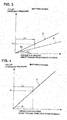
- Fig. 3 shows the map for driving, whereas Fig. 4 shows the map for coasting.
- Respective steps of the flowchart of Fig. 2 illustrating the CVT-input-torque-direction-dependent pulley hydraulic pressure control processing are hereinafter explained.
- the flowchart of Fig. 2 is repeatedly executed as time-triggered routines every predetermined time intervals.
- step S1 a target torque command value and an actual torque value from hybrid control module (HCM) 80 are read, and then the routine proceeds to step S2.
- HCM hybrid control module
- a target driving torque which is calculated by accelerator opening APO and vehicle speed VSP, is set as a target torque command value for driving.
- information about actual motor driving torque obtained by detecting a motor driving current value and the like, is set as an actual torque value.
- the summed value obtained by adding an actual driving torque of engine 1 to an actual torque value for motor generator 2 is set as an actual torque value for driving.
- a target regenerative command value (a negative torque command value) based on a calculated target regenerative torque and outputted to the motor generator 2 is set as a target torque command value for coasting. Also, during the cooperative regeneration control, information about actual generator braking torque, obtained by detecting a motor-generator power generation current value and the like, is set as an actual torque value for coasting.
- step S2 a check is made to determine whether the operating state is a driving state.
- the routine proceeds to step S3.
- NO a state other than a driving state
- driving state means a state where the direction of an input torque inputted to the belt-type continuously variable transmission CVT is a direction in which the drive road wheels are driven by the input torque from the driving source. For instance, when the target driving torque calculated by accelerator opening APO and vehicle speed VSP exceeds a preset driving-decision threshold value, it is determined that the operating state is a driving state.
- step S3 a target torque corresponding pulley hydraulic pressure Ptd for driving is calculated based on the target torque command value for driving and the map for driving shown in Fig. 3 , and then the routine proceeds to step S4.
- the target torque corresponding pulley hydraulic pressure Ptd is calculated based on a hydraulic pressure characteristic D for driving, which characteristic has a gradient Kd shown in Fig. 3 , while setting the target torque command value for driving as a torque for driving.
- step S4 an actual torque corresponding pulley hydraulic pressure Prd for driving is calculated based on the actual torque value for driving and the map for driving shown in Fig. 3 , and then the routine proceeds to step S5.
- the actual torque corresponding pulley hydraulic pressure Prd is calculated based on the hydraulic pressure characteristic D for driving, which characteristic has the gradient Kd shown in Fig. 3 , while setting the actual torque value for driving as a torque for driving.
- step S5 a higher one of the target torque corresponding pulley hydraulic pressure Ptd for driving calculated by step S3 and the actual torque corresponding pulley hydraulic pressure Prd for driving calculated by step S4 is selected by select-HIGH.
- the selected hydraulic pressure is set as a target pulley hydraulic pressure value Pd* for driving, and then the routine proceeds to step S11.
- step S6 a check is made to determine whether the operating state is a coasting state.
- the routine proceeds to step S7.
- the routine proceeds to step S10.
- coasting state means a state where the direction of an input torque inputted to the belt-type continuously variable transmission CVT is a direction in which the driving source is co-rotated by the input torque from the drive road wheels. For instance, when the target regenerative torque calculated during execution of the cooperative regeneration control exceeds a preset coasting-decision threshold value, it is determined that the operating state is a coasting state.
- step S7 a target torque corresponding pulley hydraulic pressure Ptc for coasting is calculated based on the target torque command value for coasting and the map for coasting shown in Fig. 4 , and then the routine proceeds to step S8.
- the target torque corresponding pulley hydraulic pressure Ptc is calculated based on a hydraulic pressure characteristic C for coasting, which characteristic has a gradient Kc (>Kd) shown in Fig. 4 , while setting the target torque command value for coasting as a torque for coasting.
- the setting of the gradient Kc shown in Fig. 4 greater than the gradient Kd shown in Fig. 3 means that the pulley hydraulic pressure for an input torque, derived from the map for coasting, is set higher than that derived from the map for driving.
- step S8 an actual torque corresponding pulley hydraulic pressure Prc for coasting is calculated based on the actual torque value for coasting and the map for coasting shown in Fig. 4 , and then the routine proceeds to step S9.
- the actual torque corresponding pulley hydraulic pressure Prc is calculated based on the hydraulic pressure characteristic C for coasting, which characteristic has the gradient Kc (>Kd) shown in Fig. 4 , while setting the actual torque value for coasting as a torque for coasting.
- step S9 a higher one of the target torque corresponding pulley hydraulic pressure Ptc for coasting calculated by step S7 and the actual torque corresponding pulley hydraulic pressure Prc for coasting calculated by step S8 is selected by select-HIGH.
- the selected hydraulic pressure is set as a target pulley hydraulic pressure value Pc* for coasting, and then the routine proceeds to step S11.
- step S10 a target torque corresponding pulley hydraulic pressure Pts and an actual torque corresponding pulley hydraulic pressure Prs are calculated based on the target torque command value, the actual torque value, and a low-torque-side hydraulic pressure characteristic S indicated by the broken line in Fig. 3 .
- a higher one of the target torque corresponding pulley hydraulic pressure Pts and the actual torque corresponding pulley hydraulic pressure Prs is selected by select-HIGH.
- the selected hydraulic pressure is set as a target pulley hydraulic pressure value Ps* for a low-torque range, and then the routine proceeds to step S11.
- the gradient Ks of the low-torque-side map characteristic S is set less than the gradient Kd of the hydraulic pressure characteristic D for driving, so as to reduce friction between the belt 44 and each of pulleys 42, 43.
- step S11 the calculated one of the target pulley hydraulic pressure values Pd*, Pc*, and Ps* is set as a final target pulley hydraulic pressure value P*.
- a line pressure command value for ensuring the target pulley hydraulic pressure value P* is calculated, and then the hydraulic-pressure distribution between primary hydraulic pressure Ppri and secondary hydraulic pressure Psec for obtaining a target transmission ratio at that time is determined.
- a primary hydraulic pressure command value and a secondary hydraulic pressure command value are calculated based on the determined hydraulic-pressure distribution, and then the routine proceeds to step S12.
- step S12 the line pressure command value is outputted to the line pressure solenoid 72, the primary hydraulic pressure command value is outputted to the primary hydraulic pressure solenoid 75, and the secondary hydraulic pressure command value is outputted to the secondary hydraulic pressure solenoid 78.
- the routine proceeds to "END".
- control device for the belt-type continuously variable transmission CVT of the first embodiment is classified into "CVT INPUT-TORQUE-DIRECTION-DEPENDENT PULLEY HYDRAULIC PRESSURE CONTROL PROCESSING OPERATION” and "PULLEY HYDRAULIC PRESSURE CONTROL OPERATION”.
- step S1 ⁇ step S2 ⁇ step S3 ⁇ step S4 ⁇ step S5 ⁇ step S11 ⁇ step S12 ⁇ END is repeatedly executed.
- target torque corresponding pulley hydraulic pressure Ptd and actual torque corresponding pulley hydraulic pressure Prd are calculated based on a target torque command value, an actual torque value, and the hydraulic pressure characteristic D for driving, which characteristic is indicated by the solid line in Fig. 3 , and then a higher one of these two calculated hydraulic pressures is selected by select-HIGH.
- the selected hydraulic pressure is set as a target pulley hydraulic pressure value Pd* for driving.
- step S1 ⁇ step S2 ⁇ step S6 ⁇ step S7 ⁇ step S8 ⁇ step S9 ⁇ step S11 ⁇ step S12 ⁇ END is repeatedly executed.
- target torque corresponding pulley hydraulic pressure Ptc and actual torque corresponding pulley hydraulic pressure Prc are calculated based on a target torque command value, an actual torque value, and the hydraulic pressure characteristic C for coasting, which characteristic is indicated by the solid line in Fig. 4 , and then a higher one of these two calculated hydraulic pressures is selected by select-HIGH.
- the selected hydraulic pressure is set as a target pulley hydraulic pressure value Pc* for coasting.
- step S1 ⁇ step S2 ⁇ step S6 ⁇ step S10 ⁇ step S11 ⁇ step S12 ⁇ END is repeatedly executed.
- step S10 target torque corresponding pulley hydraulic pressure Pts and actual torque corresponding pulley hydraulic pressure Prs are calculated based on a target torque command value, an actual torque value, and the low-torque-side hydraulic pressure characteristic S, which characteristic is indicated by the broken line in Fig. 3 , and then a higher one of these two calculated hydraulic pressures is selected by select-HIGH.
- the selected hydraulic pressure is set as a target pulley hydraulic pressure value Ps* for a low-torque range.
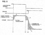
- Fig. 5 shows respective characteristics, obtained when, in the FF hybrid vehicle to which the control device of the first embodiment is applied, a series of operations has been made from accelerator depressing operation via accelerator releasing operation to brake depressing operation, in that order.
- the pulley hydraulic pressure control operation is hereunder explained in reference to Fig. 5 .
- a target torque command value (a target driving torque command value) exhibits such characteristic as to increase, while following an increase in accelerator opening.
- an actual torque value exhibits such characteristic as to be brought closer to the target torque command value with a response delay from the increase in accelerator opening.
- target torque corresponding pulley hydraulic pressure Ptd and actual torque corresponding pulley hydraulic pressure Prd are calculated based on a target driving torque command value, an actual driving torque value, and the hydraulic pressure characteristic D for driving, which characteristic is indicated by the solid line in Fig. 3 .
- a higher one of these two calculated hydraulic pressures that is, target torque corresponding pulley hydraulic pressure Ptd, is selected by select-HIGH.
- the selected hydraulic pressure is set as a target pulley hydraulic pressure value Pd* for driving.
- the hydraulic responsiveness of pulley hydraulic pressure is lower than the responsiveness of an electric motor. Therefore, assuming that, in a driving state, a target pulley hydraulic pressure P* is set based on an actual driving torque value, there is a possibility of a slippage of belt 44 due to a lack of belt clamping force caused by the delay in a pulley hydraulic pressure rise.
- a target torque command value (a target driving torque command value) exhibits such characteristic as to decrease, while following a decrease in accelerator opening.
- an actual torque value exhibits such characteristic as to be gradually brought closer to the target torque command value with a response delay from the decrease in accelerator opening.
- target torque corresponding pulley hydraulic pressure Pts and actual torque corresponding pulley hydraulic pressure Prs are calculated based on a target driving torque command value, an actual driving torque value, and the low-torque-side hydraulic pressure characteristic S, which characteristic is indicated by the broken line in Fig. 3 .
- a higher one of these two calculated hydraulic pressures, that is, actual torque corresponding pulley hydraulic pressure Prs is selected by select-HIGH.
- the selected hydraulic pressure is set as a target pulley hydraulic pressure value Ps* for a low-torque range.
- target pulley hydraulic pressure P* is set based on a target driving torque command value
- target pulley hydraulic pressure P* is set based on an actual driving torque value having a response delay with respect to the target driving torque command value.
- the shading area "F" of Fig. 5 represents a late pressure release area of pulley hydraulic pressure. Therefore, it is possible to gradually reduce both the primary hydraulic pressure Ppri and the secondary hydraulic pressure Psec in concert with the decrease of the actual driving torque value, thereby preventing a slippage of belt 44 in a transient region corresponding to a transition period to a low-torque state caused by accelerator releasing operation.
- a target torque command value (a target regenerative torque command value to motor generator 2) exhibits such characteristic as to decrease immediately when the cooperative regeneration control is initiated.
- an actual torque value (an actual regenerative torque value) exhibits such characteristic as to be brought closer to the target regenerative torque command value with a response delay from the brake depressing operation.
- target torque corresponding pulley hydraulic pressure Ptc and actual torque corresponding pulley hydraulic pressure Prc are calculated based on a target regenerative torque command value, an actual regenerative torque value, and the hydraulic pressure characteristic C for coasting, which characteristic is indicated by the solid line in Fig. 4 .
- a higher one of these two calculated hydraulic pressures that is, target torque corresponding pulley hydraulic pressure Ptc, is selected by select-HIGH.
- the selected hydraulic pressure is set as a target pulley hydraulic pressure value Pc* for coasting.
Landscapes
- Engineering & Computer Science (AREA)
- Mechanical Engineering (AREA)
- General Engineering & Computer Science (AREA)
- Transportation (AREA)
- Chemical & Material Sciences (AREA)
- Combustion & Propulsion (AREA)
- Automation & Control Theory (AREA)
- Power Engineering (AREA)
- Hybrid Electric Vehicles (AREA)
- Control Of Transmission Device (AREA)
- Electric Propulsion And Braking For Vehicles (AREA)
Claims (3)
- Transmission variable en continu de type à courroie munie d'une source d'entraînement (1, 2) comportant un groupe moteur générateur (2), une poulie primaire (42) raccordée à la source d'entraînement (1, 2), une poulie secondaire (43) raccordée aux roues d'entraînement (6, 6), une courroie (44) enroulée tout autour de la poulie primaire (42) et de la poulie secondaire (43), un moyen de commande de pression hydraulique de poulie (81) permettant de commander les pressions hydrauliques de poulie sur la poulie primaire (42) et la poulie secondaire (43) et un dispositif de commande comprenant :un moyen de détermination d'état de fonctionnement permettant de déterminer si l'état de fonctionnement est état de conduite dans lequel le sens du couple d'entrée appliqué à la transmission variable en continu de type à courroie est un sens dans lequel les roues d'entraînement (6, 6) sont entraînées par le couple d'entrée à partir de la source d'entraînement (1, 2) ou bien un état de marche en roue libre dans lequel le sens du couple d'entrée est un sens dans lequel la source d'entraînement (1, 2) est co-entraînée en rotation par le couple d'entrée à partir des roues d'entraînement (6, 6),dans lequel le moyen de commande de pression hydraulique de poulie (81) règle la pression hydraulique de poulie pour le couple d'entrée, pour le moment où il est déterminé que l'état de fonctionnement est l'état de marche en roue libre, à une valeur plus forte que la pression hydraulique de poulie pour le couple d'entrée, pour le moment où il est déterminé que l'état de fonctionnement est l'état de conduite,caractérisé en ce quele moyen de détermination d'état de fonctionnement définit que l'état de fonctionnement est l'état de marche en roue libre lorsqu'un freinage régénératif est effectué par le groupe moteur générateur (2),le moyen de commande de pression hydraulique de poulie (81) comporte une carte pour la conduite, correspondant à une caractéristique de pression hydraulique (D) pour la conduite montrant la relation existant entre le couple de conduite et la pression hydraulique de poulie, et une carte pour la marche en roue libre, correspondant à une caractéristique de pression hydraulique (C) pour la marche en roue libre montrant la relation existant entre le couple permettant la marche en roue libre et la pression hydraulique de poulie, le gradient (Kc) de la caractéristique de pression hydraulique (C) pour la marche en roue libre étant réglé pour être plus grand que le gradient (Kd) de la caractéristique de pression hydraulique (D) pour la conduite de sorte que, pour un même couple d'entrée, la pression hydraulique de poulie déduite de la carte pour la marche en roue libre est réglée pour être supérieure à celle déduite de la carte pour la conduite, etle moyen de commande de pression hydraulique de poulie (81) règle une pression hydraulique cible de poulie (Pc*) en utilisant la carte pour la marche en roue libre lorsqu'il est déterminé que l'état de fonctionnement est l'état de marche en roue libre.
- Transmission variable en continu de type à courroie selon la revendication 1, dans laquelle
lorsqu'il est déterminé que l'état de fonctionnement est l'état de marche en roue libre, le moyen de commande de pression hydraulique de poulie (81) calcule une pression hydraulique de poulie (Ptc) correspondant au couple cible pour la marche en roue libre, en utilisant le couple pour la marche en roue libre, correspondant à une valeur de commande de couple cible, et la caractéristique de pression hydraulique (C) pour la marche en roue libre, et il calcule une pression hydraulique de poulie (Prc) correspondant au couple réel pour la marche en roue libre, en utilisant le couple pour la marche en roue libre, correspondant à une valeur de couple réel, et la caractéristique de pression hydraulique (C) pour la marche en roue libre, et il règle la pression hydraulique cible de poulie (Pc*) comme étant la plus grande parmi la pression hydraulique de poulie (Ptc) correspondant au couple cible pour la marche en roue libre et la pression hydraulique de poulie (Prc) correspondant au couple réel pour la marche en roue libre, sélectionnée par la commande select-HIGH. - Transmission variable en continu de type à courroie selon la revendication 1 ou la revendication 2, dans laquelle
lorsqu'il est déterminé que l'état de fonctionnement est l'état de conduite, le moyen de commande de pression hydraulique de poulie (81) calcule une pression hydraulique de poulie (Ptd) correspondant au couple cible pour la conduite, en utilisant le couple pour la conduite, correspondant à une valeur de commande de couple cible, et la caractéristique de pression hydraulique (D) pour la conduite, et il calcule une pression hydraulique de poulie (Prd) correspondant au couple réel pour la conduite, en utilisant le couple pour la conduite, correspondant à une valeur de couple réel, et la caractéristique de pression hydraulique (D) pour la conduite, et il règle la pression hydraulique cible de poulie (Pd*) comme étant la plus grande parmi la pression hydraulique de poulie (Ptd) correspondant au couple cible pour la conduite et la pression hydraulique de poulie (Prd) correspondant au couple réel pour la conduite, sélectionnée par la commande select-HIGH.
Applications Claiming Priority (2)
| Application Number | Priority Date | Filing Date | Title |
|---|---|---|---|
| JP2013059807 | 2013-03-22 | ||
| PCT/JP2014/052375 WO2014148124A1 (fr) | 2013-03-22 | 2014-02-03 | Dispositif de commande pour transmission variable en continu de type à courroie |
Publications (3)
| Publication Number | Publication Date |
|---|---|
| EP2977649A1 EP2977649A1 (fr) | 2016-01-27 |
| EP2977649A4 EP2977649A4 (fr) | 2017-04-19 |
| EP2977649B1 true EP2977649B1 (fr) | 2020-06-24 |
Family
ID=51579819
Family Applications (1)
| Application Number | Title | Priority Date | Filing Date |
|---|---|---|---|
| EP14769757.7A Active EP2977649B1 (fr) | 2013-03-22 | 2014-02-03 | Transmission variable en continu de type à courroie |
Country Status (6)
| Country | Link |
|---|---|
| US (1) | US9989150B2 (fr) |
| EP (1) | EP2977649B1 (fr) |
| JP (1) | JP5937751B2 (fr) |
| KR (1) | KR101698712B1 (fr) |
| CN (1) | CN105190110B (fr) |
| WO (1) | WO2014148124A1 (fr) |
Families Citing this family (19)
| Publication number | Priority date | Publication date | Assignee | Title |
|---|---|---|---|---|
| JP6196857B2 (ja) * | 2013-09-13 | 2017-09-13 | ジヤトコ株式会社 | 車両の制御装置 |
| EP3179139A4 (fr) * | 2014-08-05 | 2018-02-28 | Jatco Ltd | Dispositif de commande pour transmission variable en continu |
| WO2016151663A1 (fr) | 2015-03-20 | 2016-09-29 | 日産自動車株式会社 | Dispositif de régulation de vitesse de véhicule par récupération |
| WO2016152337A1 (fr) * | 2015-03-23 | 2016-09-29 | ジヤトコ株式会社 | Véhicule et procédé de commande de véhicule |
| JP6402240B2 (ja) * | 2015-03-23 | 2018-10-10 | ジヤトコ株式会社 | 車両制御装置、及び車両の制御方法 |
| CN107531155B (zh) * | 2015-04-27 | 2020-05-22 | 加特可株式会社 | 车辆的显示转速控制装置 |
| KR101673355B1 (ko) * | 2015-07-13 | 2016-11-16 | 현대자동차 주식회사 | 차량의 타력 주행 토크 제어시스템 및 이에 의한 제어방법 |
| KR102000891B1 (ko) * | 2015-09-09 | 2019-07-16 | 쟈트코 가부시키가이샤 | 차량용 무단 변속 기구의 제어 장치 및 제어 방법 |
| US10619586B2 (en) | 2018-03-27 | 2020-04-14 | GM Global Technology Operations LLC | Consolidation of constraints in model predictive control |
| US10661804B2 (en) * | 2018-04-10 | 2020-05-26 | GM Global Technology Operations LLC | Shift management in model predictive based propulsion system control |
| CN108749643B (zh) * | 2018-04-17 | 2023-06-13 | 江西精骏电控技术有限公司 | 一种电动汽车启动扭矩方向检测装置及其检测方法 |
| CN112601684B (zh) * | 2018-09-10 | 2024-08-13 | 加特可株式会社 | 自动变速器的油压控制装置及油压控制方法 |
| CN109322990B (zh) * | 2018-11-13 | 2020-01-14 | 安徽江淮汽车集团股份有限公司 | 一种滑行工况扭矩控制方法 |
| US10859159B2 (en) | 2019-02-11 | 2020-12-08 | GM Global Technology Operations LLC | Model predictive control of torque converter clutch slip |
| US11192561B2 (en) | 2019-05-21 | 2021-12-07 | GM Global Technology Operations LLC | Method for increasing control performance of model predictive control cost functions |
| US11312208B2 (en) | 2019-08-26 | 2022-04-26 | GM Global Technology Operations LLC | Active thermal management system and method for flow control |
| US11008921B1 (en) | 2019-11-06 | 2021-05-18 | GM Global Technology Operations LLC | Selective catalytic reduction device control |
| GB2594279B (en) * | 2020-04-21 | 2023-03-08 | Jaguar Land Rover Ltd | Belt integrated starter generator torque control |
| CN113503358B (zh) * | 2021-07-22 | 2022-07-01 | 湖南容大智能变速器股份有限公司 | 基于cvt液压系统的单压力传感器电磁阀自学习方法 |
Family Cites Families (18)
| Publication number | Priority date | Publication date | Assignee | Title |
|---|---|---|---|---|
| JPS6252264A (ja) | 1985-08-30 | 1987-03-06 | Fuji Heavy Ind Ltd | 無段変速機の油圧制御装置 |
| JP2876209B2 (ja) * | 1987-10-09 | 1999-03-31 | 富士重工業株式会社 | 無段変速機の制御装置 |
| JP2878925B2 (ja) * | 1993-03-31 | 1999-04-05 | 本田技研工業株式会社 | ベルト式無段変速機のプーリ側圧制御装置 |
| JP4277423B2 (ja) * | 2000-05-23 | 2009-06-10 | トヨタ自動車株式会社 | ベルト式無段変速機の制御装置 |
| JP4821054B2 (ja) * | 2001-05-18 | 2011-11-24 | トヨタ自動車株式会社 | 車両用制御装置 |
| JP3912235B2 (ja) | 2002-09-10 | 2007-05-09 | トヨタ自動車株式会社 | 車両の油圧制御装置 |
| ATE388355T1 (de) * | 2004-10-27 | 2008-03-15 | Bosch Gmbh Robert | Mit einer steuervorrichtung versehenes stufenloses getriebe |
| JP2006336796A (ja) | 2005-06-03 | 2006-12-14 | Nissan Motor Co Ltd | ベルト式無段変速機の制御装置 |
| JP4375321B2 (ja) * | 2005-10-31 | 2009-12-02 | トヨタ自動車株式会社 | 無段変速機の変速制御装置 |
| JP4844493B2 (ja) * | 2007-07-27 | 2011-12-28 | トヨタ自動車株式会社 | ハイブリッド車の制御装置 |
| JP4211862B1 (ja) * | 2007-09-28 | 2009-01-21 | トヨタ自動車株式会社 | 無段変速機の制御装置 |
| JP5207925B2 (ja) * | 2008-11-11 | 2013-06-12 | 株式会社エフ・シー・シー | ハイブリッド車両の動力伝達装置 |
| JP2010127423A (ja) * | 2008-11-28 | 2010-06-10 | Toyota Motor Corp | 車両の制御装置 |
| MX2011011418A (es) * | 2009-04-30 | 2012-02-13 | Nissan Motor | Controlador y metodo de control de transmision continuamente variable de tipo de banda. |
| JP5039819B2 (ja) * | 2010-09-01 | 2012-10-03 | ジヤトコ株式会社 | コーストストップ車両及びコーストストップ方法 |
| JP5853505B2 (ja) * | 2011-09-01 | 2016-02-09 | 日産自動車株式会社 | 車両の回生発電制御装置 |
| JP2013127287A (ja) * | 2011-12-19 | 2013-06-27 | Nissan Motor Co Ltd | Vベルト式無段変速機のベルト挟圧力制御装置 |
| CN104797475B (zh) * | 2012-11-16 | 2016-08-24 | 日产自动车株式会社 | 混合动力车辆的控制装置 |
-
2014
- 2014-02-03 US US14/777,641 patent/US9989150B2/en active Active
- 2014-02-03 JP JP2015506636A patent/JP5937751B2/ja active Active
- 2014-02-03 EP EP14769757.7A patent/EP2977649B1/fr active Active
- 2014-02-03 KR KR1020157021285A patent/KR101698712B1/ko not_active Expired - Fee Related
- 2014-02-03 WO PCT/JP2014/052375 patent/WO2014148124A1/fr not_active Ceased
- 2014-02-03 CN CN201480016466.9A patent/CN105190110B/zh active Active
Non-Patent Citations (1)
| Title |
|---|
| None * |
Also Published As
| Publication number | Publication date |
|---|---|
| EP2977649A4 (fr) | 2017-04-19 |
| US20160290502A1 (en) | 2016-10-06 |
| US9989150B2 (en) | 2018-06-05 |
| JP5937751B2 (ja) | 2016-06-22 |
| EP2977649A1 (fr) | 2016-01-27 |
| KR20150105414A (ko) | 2015-09-16 |
| CN105190110B (zh) | 2017-03-15 |
| JPWO2014148124A1 (ja) | 2017-02-16 |
| CN105190110A (zh) | 2015-12-23 |
| KR101698712B1 (ko) | 2017-01-20 |
| WO2014148124A1 (fr) | 2014-09-25 |
Similar Documents
| Publication | Publication Date | Title |
|---|---|---|
| EP2977649B1 (fr) | Transmission variable en continu de type à courroie | |
| KR100908950B1 (ko) | 차량의 제어 장치 | |
| CN107636362B (zh) | 车辆的再生变速控制装置 | |
| EP2634052B1 (fr) | Dispositif de commande de démarrage d'un moteur thermique pour véhicule électrique hybride | |
| JP5521340B2 (ja) | ハイブリッド車両の制御装置 | |
| RU2657658C1 (ru) | Устройство управления демпфированием для гибридного транспортного средства | |
| US10253876B2 (en) | Vehicle regenerative speed control device | |
| EP3231679B1 (fr) | Dispositif de commande de véhicule hybride et procédé de commande de véhicule hybride | |
| US20170015301A1 (en) | Hybrid vehicle control device | |
| CN107406067B (zh) | 混合动力车辆的控制装置 | |
| CN107407401A (zh) | 车辆及车辆的控制方法 | |
| WO2018189896A1 (fr) | Dispositif de commande de véhicule électrique et procédé de commande de véhicule électrique | |
| JP6747583B2 (ja) | 電動車両の制御方法及び電動車両の制御装置 | |
| JP6207269B2 (ja) | ベルト式無段変速機の制御装置 | |
| JP2012206663A (ja) | ハイブリッド車両の変速制御装置 | |
| JP2018069960A (ja) | 電動車両の制御装置 | |
| JP6741150B2 (ja) | 電動車両の制御装置および電動車両の制御方法 | |
| JP6355308B2 (ja) | ベルト式無段変速機の制御装置 | |
| JP6400148B2 (ja) | ベルト式無段変速機の制御装置 |
Legal Events
| Date | Code | Title | Description |
|---|---|---|---|
| PUAI | Public reference made under article 153(3) epc to a published international application that has entered the european phase |
Free format text: ORIGINAL CODE: 0009012 |
|
| 17P | Request for examination filed |
Effective date: 20150922 |
|
| AK | Designated contracting states |
Kind code of ref document: A1 Designated state(s): AL AT BE BG CH CY CZ DE DK EE ES FI FR GB GR HR HU IE IS IT LI LT LU LV MC MK MT NL NO PL PT RO RS SE SI SK SM TR |
|
| AX | Request for extension of the european patent |
Extension state: BA ME |
|
| DAX | Request for extension of the european patent (deleted) | ||
| A4 | Supplementary search report drawn up and despatched |
Effective date: 20170316 |
|
| RIC1 | Information provided on ipc code assigned before grant |
Ipc: B60W 20/00 20160101ALI20170311BHEP Ipc: B60K 6/48 20071001AFI20170311BHEP Ipc: F16H 61/662 20060101ALI20170311BHEP Ipc: B60W 10/10 20120101ALI20170311BHEP Ipc: B60K 6/543 20071001ALI20170311BHEP |
|
| RIC1 | Information provided on ipc code assigned before grant |
Ipc: B60W 20/00 20160101ALI20171208BHEP Ipc: B60K 6/543 20071001ALI20171208BHEP Ipc: B60K 6/48 20071001AFI20171208BHEP Ipc: B60W 10/10 20120101ALI20171208BHEP Ipc: F16H 61/662 20060101ALI20171208BHEP |
|
| STAA | Information on the status of an ep patent application or granted ep patent |
Free format text: STATUS: EXAMINATION IS IN PROGRESS |
|
| 17Q | First examination report despatched |
Effective date: 20180201 |
|
| RIC1 | Information provided on ipc code assigned before grant |
Ipc: B60W 20/00 20160101ALI20171208BHEP Ipc: B60K 6/543 20071001ALI20171208BHEP Ipc: F16H 61/662 20060101ALI20171208BHEP Ipc: B60K 6/48 20071001AFI20171208BHEP Ipc: B60W 10/10 20120101ALI20171208BHEP |
|
| REG | Reference to a national code |
Ref country code: DE Ref legal event code: R079 Ref document number: 602014067009 Country of ref document: DE Free format text: PREVIOUS MAIN CLASS: F16H0061000000 Ipc: B60K0006480000 |
|
| GRAP | Despatch of communication of intention to grant a patent |
Free format text: ORIGINAL CODE: EPIDOSNIGR1 |
|
| RIC1 | Information provided on ipc code assigned before grant |
Ipc: B60K 6/48 20071001AFI20191218BHEP Ipc: B60W 30/18 20120101ALI20191218BHEP Ipc: B60W 10/107 20120101ALI20191218BHEP Ipc: F16H 61/662 20060101ALI20191218BHEP Ipc: B60W 20/00 20160101ALI20191218BHEP Ipc: B60K 6/543 20071001ALI20191218BHEP |
|
| STAA | Information on the status of an ep patent application or granted ep patent |
Free format text: STATUS: GRANT OF PATENT IS INTENDED |
|
| INTG | Intention to grant announced |
Effective date: 20200123 |
|
| GRAS | Grant fee paid |
Free format text: ORIGINAL CODE: EPIDOSNIGR3 |
|
| GRAA | (expected) grant |
Free format text: ORIGINAL CODE: 0009210 |
|
| STAA | Information on the status of an ep patent application or granted ep patent |
Free format text: STATUS: THE PATENT HAS BEEN GRANTED |
|
| AK | Designated contracting states |
Kind code of ref document: B1 Designated state(s): AL AT BE BG CH CY CZ DE DK EE ES FI FR GB GR HR HU IE IS IT LI LT LU LV MC MK MT NL NO PL PT RO RS SE SI SK SM TR |
|
| REG | Reference to a national code |
Ref country code: GB Ref legal event code: FG4D |
|
| REG | Reference to a national code |
Ref country code: CH Ref legal event code: EP |
|
| REG | Reference to a national code |
Ref country code: DE Ref legal event code: R096 Ref document number: 602014067009 Country of ref document: DE |
|
| REG | Reference to a national code |
Ref country code: AT Ref legal event code: REF Ref document number: 1283543 Country of ref document: AT Kind code of ref document: T Effective date: 20200715 |
|
| REG | Reference to a national code |
Ref country code: IE Ref legal event code: FG4D |
|
| PG25 | Lapsed in a contracting state [announced via postgrant information from national office to epo] |
Ref country code: LT Free format text: LAPSE BECAUSE OF FAILURE TO SUBMIT A TRANSLATION OF THE DESCRIPTION OR TO PAY THE FEE WITHIN THE PRESCRIBED TIME-LIMIT Effective date: 20200624 Ref country code: SE Free format text: LAPSE BECAUSE OF FAILURE TO SUBMIT A TRANSLATION OF THE DESCRIPTION OR TO PAY THE FEE WITHIN THE PRESCRIBED TIME-LIMIT Effective date: 20200624 Ref country code: NO Free format text: LAPSE BECAUSE OF FAILURE TO SUBMIT A TRANSLATION OF THE DESCRIPTION OR TO PAY THE FEE WITHIN THE PRESCRIBED TIME-LIMIT Effective date: 20200924 Ref country code: GR Free format text: LAPSE BECAUSE OF FAILURE TO SUBMIT A TRANSLATION OF THE DESCRIPTION OR TO PAY THE FEE WITHIN THE PRESCRIBED TIME-LIMIT Effective date: 20200925 Ref country code: FI Free format text: LAPSE BECAUSE OF FAILURE TO SUBMIT A TRANSLATION OF THE DESCRIPTION OR TO PAY THE FEE WITHIN THE PRESCRIBED TIME-LIMIT Effective date: 20200624 |
|
| REG | Reference to a national code |
Ref country code: LT Ref legal event code: MG4D |
|
| PG25 | Lapsed in a contracting state [announced via postgrant information from national office to epo] |
Ref country code: RS Free format text: LAPSE BECAUSE OF FAILURE TO SUBMIT A TRANSLATION OF THE DESCRIPTION OR TO PAY THE FEE WITHIN THE PRESCRIBED TIME-LIMIT Effective date: 20200624 Ref country code: LV Free format text: LAPSE BECAUSE OF FAILURE TO SUBMIT A TRANSLATION OF THE DESCRIPTION OR TO PAY THE FEE WITHIN THE PRESCRIBED TIME-LIMIT Effective date: 20200624 Ref country code: HR Free format text: LAPSE BECAUSE OF FAILURE TO SUBMIT A TRANSLATION OF THE DESCRIPTION OR TO PAY THE FEE WITHIN THE PRESCRIBED TIME-LIMIT Effective date: 20200624 Ref country code: BG Free format text: LAPSE BECAUSE OF FAILURE TO SUBMIT A TRANSLATION OF THE DESCRIPTION OR TO PAY THE FEE WITHIN THE PRESCRIBED TIME-LIMIT Effective date: 20200924 |
|
| REG | Reference to a national code |
Ref country code: NL Ref legal event code: MP Effective date: 20200624 |
|
| REG | Reference to a national code |
Ref country code: AT Ref legal event code: MK05 Ref document number: 1283543 Country of ref document: AT Kind code of ref document: T Effective date: 20200624 |
|
| PG25 | Lapsed in a contracting state [announced via postgrant information from national office to epo] |
Ref country code: NL Free format text: LAPSE BECAUSE OF FAILURE TO SUBMIT A TRANSLATION OF THE DESCRIPTION OR TO PAY THE FEE WITHIN THE PRESCRIBED TIME-LIMIT Effective date: 20200624 Ref country code: AL Free format text: LAPSE BECAUSE OF FAILURE TO SUBMIT A TRANSLATION OF THE DESCRIPTION OR TO PAY THE FEE WITHIN THE PRESCRIBED TIME-LIMIT Effective date: 20200624 |
|
| PG25 | Lapsed in a contracting state [announced via postgrant information from national office to epo] |
Ref country code: EE Free format text: LAPSE BECAUSE OF FAILURE TO SUBMIT A TRANSLATION OF THE DESCRIPTION OR TO PAY THE FEE WITHIN THE PRESCRIBED TIME-LIMIT Effective date: 20200624 Ref country code: SM Free format text: LAPSE BECAUSE OF FAILURE TO SUBMIT A TRANSLATION OF THE DESCRIPTION OR TO PAY THE FEE WITHIN THE PRESCRIBED TIME-LIMIT Effective date: 20200624 Ref country code: IT Free format text: LAPSE BECAUSE OF FAILURE TO SUBMIT A TRANSLATION OF THE DESCRIPTION OR TO PAY THE FEE WITHIN THE PRESCRIBED TIME-LIMIT Effective date: 20200624 Ref country code: RO Free format text: LAPSE BECAUSE OF FAILURE TO SUBMIT A TRANSLATION OF THE DESCRIPTION OR TO PAY THE FEE WITHIN THE PRESCRIBED TIME-LIMIT Effective date: 20200624 Ref country code: CZ Free format text: LAPSE BECAUSE OF FAILURE TO SUBMIT A TRANSLATION OF THE DESCRIPTION OR TO PAY THE FEE WITHIN THE PRESCRIBED TIME-LIMIT Effective date: 20200624 Ref country code: PT Free format text: LAPSE BECAUSE OF FAILURE TO SUBMIT A TRANSLATION OF THE DESCRIPTION OR TO PAY THE FEE WITHIN THE PRESCRIBED TIME-LIMIT Effective date: 20201026 Ref country code: ES Free format text: LAPSE BECAUSE OF FAILURE TO SUBMIT A TRANSLATION OF THE DESCRIPTION OR TO PAY THE FEE WITHIN THE PRESCRIBED TIME-LIMIT Effective date: 20200624 Ref country code: AT Free format text: LAPSE BECAUSE OF FAILURE TO SUBMIT A TRANSLATION OF THE DESCRIPTION OR TO PAY THE FEE WITHIN THE PRESCRIBED TIME-LIMIT Effective date: 20200624 |
|
| PG25 | Lapsed in a contracting state [announced via postgrant information from national office to epo] |
Ref country code: IS Free format text: LAPSE BECAUSE OF FAILURE TO SUBMIT A TRANSLATION OF THE DESCRIPTION OR TO PAY THE FEE WITHIN THE PRESCRIBED TIME-LIMIT Effective date: 20201024 Ref country code: SK Free format text: LAPSE BECAUSE OF FAILURE TO SUBMIT A TRANSLATION OF THE DESCRIPTION OR TO PAY THE FEE WITHIN THE PRESCRIBED TIME-LIMIT Effective date: 20200624 Ref country code: PL Free format text: LAPSE BECAUSE OF FAILURE TO SUBMIT A TRANSLATION OF THE DESCRIPTION OR TO PAY THE FEE WITHIN THE PRESCRIBED TIME-LIMIT Effective date: 20200624 |
|
| REG | Reference to a national code |
Ref country code: DE Ref legal event code: R097 Ref document number: 602014067009 Country of ref document: DE |
|
| PG25 | Lapsed in a contracting state [announced via postgrant information from national office to epo] |
Ref country code: DK Free format text: LAPSE BECAUSE OF FAILURE TO SUBMIT A TRANSLATION OF THE DESCRIPTION OR TO PAY THE FEE WITHIN THE PRESCRIBED TIME-LIMIT Effective date: 20200624 |
|
| PLBE | No opposition filed within time limit |
Free format text: ORIGINAL CODE: 0009261 |
|
| STAA | Information on the status of an ep patent application or granted ep patent |
Free format text: STATUS: NO OPPOSITION FILED WITHIN TIME LIMIT |
|
| 26N | No opposition filed |
Effective date: 20210325 |
|
| PG25 | Lapsed in a contracting state [announced via postgrant information from national office to epo] |
Ref country code: SI Free format text: LAPSE BECAUSE OF FAILURE TO SUBMIT A TRANSLATION OF THE DESCRIPTION OR TO PAY THE FEE WITHIN THE PRESCRIBED TIME-LIMIT Effective date: 20200624 |
|
| PG25 | Lapsed in a contracting state [announced via postgrant information from national office to epo] |
Ref country code: MC Free format text: LAPSE BECAUSE OF FAILURE TO SUBMIT A TRANSLATION OF THE DESCRIPTION OR TO PAY THE FEE WITHIN THE PRESCRIBED TIME-LIMIT Effective date: 20200624 |
|
| GBPC | Gb: european patent ceased through non-payment of renewal fee |
Effective date: 20210203 |
|
| REG | Reference to a national code |
Ref country code: BE Ref legal event code: MM Effective date: 20210228 |
|
| PG25 | Lapsed in a contracting state [announced via postgrant information from national office to epo] |
Ref country code: CH Free format text: LAPSE BECAUSE OF NON-PAYMENT OF DUE FEES Effective date: 20210228 Ref country code: LU Free format text: LAPSE BECAUSE OF NON-PAYMENT OF DUE FEES Effective date: 20210203 Ref country code: LI Free format text: LAPSE BECAUSE OF NON-PAYMENT OF DUE FEES Effective date: 20210228 |
|
| PG25 | Lapsed in a contracting state [announced via postgrant information from national office to epo] |
Ref country code: FR Free format text: LAPSE BECAUSE OF NON-PAYMENT OF DUE FEES Effective date: 20210228 Ref country code: GB Free format text: LAPSE BECAUSE OF NON-PAYMENT OF DUE FEES Effective date: 20210203 Ref country code: IE Free format text: LAPSE BECAUSE OF NON-PAYMENT OF DUE FEES Effective date: 20210203 |
|
| PG25 | Lapsed in a contracting state [announced via postgrant information from national office to epo] |
Ref country code: BE Free format text: LAPSE BECAUSE OF NON-PAYMENT OF DUE FEES Effective date: 20210228 |
|
| PG25 | Lapsed in a contracting state [announced via postgrant information from national office to epo] |
Ref country code: HU Free format text: LAPSE BECAUSE OF FAILURE TO SUBMIT A TRANSLATION OF THE DESCRIPTION OR TO PAY THE FEE WITHIN THE PRESCRIBED TIME-LIMIT; INVALID AB INITIO Effective date: 20140203 |
|
| PG25 | Lapsed in a contracting state [announced via postgrant information from national office to epo] |
Ref country code: CY Free format text: LAPSE BECAUSE OF FAILURE TO SUBMIT A TRANSLATION OF THE DESCRIPTION OR TO PAY THE FEE WITHIN THE PRESCRIBED TIME-LIMIT Effective date: 20200624 |
|
| PG25 | Lapsed in a contracting state [announced via postgrant information from national office to epo] |
Ref country code: MK Free format text: LAPSE BECAUSE OF FAILURE TO SUBMIT A TRANSLATION OF THE DESCRIPTION OR TO PAY THE FEE WITHIN THE PRESCRIBED TIME-LIMIT Effective date: 20200624 |
|
| PG25 | Lapsed in a contracting state [announced via postgrant information from national office to epo] |
Ref country code: MT Free format text: LAPSE BECAUSE OF FAILURE TO SUBMIT A TRANSLATION OF THE DESCRIPTION OR TO PAY THE FEE WITHIN THE PRESCRIBED TIME-LIMIT Effective date: 20200624 |
|
| PG25 | Lapsed in a contracting state [announced via postgrant information from national office to epo] |
Ref country code: TR Free format text: LAPSE BECAUSE OF FAILURE TO SUBMIT A TRANSLATION OF THE DESCRIPTION OR TO PAY THE FEE WITHIN THE PRESCRIBED TIME-LIMIT Effective date: 20200624 |
|
| PGFP | Annual fee paid to national office [announced via postgrant information from national office to epo] |
Ref country code: DE Payment date: 20251230 Year of fee payment: 13 |