EP2985489A2 - Système de suspension de bicyclette - Google Patents
Système de suspension de bicyclette Download PDFInfo
- Publication number
- EP2985489A2 EP2985489A2 EP15181158.5A EP15181158A EP2985489A2 EP 2985489 A2 EP2985489 A2 EP 2985489A2 EP 15181158 A EP15181158 A EP 15181158A EP 2985489 A2 EP2985489 A2 EP 2985489A2
- Authority
- EP
- European Patent Office
- Prior art keywords
- bicycle
- frame member
- suspension system
- disposed
- valve
- Prior art date
- Legal status (The legal status is an assumption and is not a legal conclusion. Google has not performed a legal analysis and makes no representation as to the accuracy of the status listed.)
- Withdrawn
Links
Images




Classifications
-
- B—PERFORMING OPERATIONS; TRANSPORTING
- B62—LAND VEHICLES FOR TRAVELLING OTHERWISE THAN ON RAILS
- B62K—CYCLES; CYCLE FRAMES; CYCLE STEERING DEVICES; RIDER-OPERATED TERMINAL CONTROLS SPECIALLY ADAPTED FOR CYCLES; CYCLE AXLE SUSPENSIONS; CYCLE SIDECARS, FORECARS, OR THE LIKE
- B62K19/00—Cycle frames
- B62K19/18—Joints between frame members
-
- B—PERFORMING OPERATIONS; TRANSPORTING
- B62—LAND VEHICLES FOR TRAVELLING OTHERWISE THAN ON RAILS
- B62K—CYCLES; CYCLE FRAMES; CYCLE STEERING DEVICES; RIDER-OPERATED TERMINAL CONTROLS SPECIALLY ADAPTED FOR CYCLES; CYCLE AXLE SUSPENSIONS; CYCLE SIDECARS, FORECARS, OR THE LIKE
- B62K25/00—Axle suspensions
- B62K25/04—Axle suspensions for mounting axles resiliently on cycle frame or fork
- B62K25/28—Axle suspensions for mounting axles resiliently on cycle frame or fork with pivoted chain-stay
- B62K25/286—Axle suspensions for mounting axles resiliently on cycle frame or fork with pivoted chain-stay the shock absorber being connected to the chain-stay via a linkage mechanism
-
- B—PERFORMING OPERATIONS; TRANSPORTING
- B62—LAND VEHICLES FOR TRAVELLING OTHERWISE THAN ON RAILS
- B62K—CYCLES; CYCLE FRAMES; CYCLE STEERING DEVICES; RIDER-OPERATED TERMINAL CONTROLS SPECIALLY ADAPTED FOR CYCLES; CYCLE AXLE SUSPENSIONS; CYCLE SIDECARS, FORECARS, OR THE LIKE
- B62K25/00—Axle suspensions
- B62K25/04—Axle suspensions for mounting axles resiliently on cycle frame or fork
- B62K25/28—Axle suspensions for mounting axles resiliently on cycle frame or fork with pivoted chain-stay
- B62K25/30—Axle suspensions for mounting axles resiliently on cycle frame or fork with pivoted chain-stay pivoted on pedal crank shelf
-
- F—MECHANICAL ENGINEERING; LIGHTING; HEATING; WEAPONS; BLASTING
- F16—ENGINEERING ELEMENTS AND UNITS; GENERAL MEASURES FOR PRODUCING AND MAINTAINING EFFECTIVE FUNCTIONING OF MACHINES OR INSTALLATIONS; THERMAL INSULATION IN GENERAL
- F16F—SPRINGS; SHOCK-ABSORBERS; MEANS FOR DAMPING VIBRATION
- F16F9/00—Springs, vibration-dampers, shock-absorbers, or similarly-constructed movement-dampers using a fluid or the equivalent as damping medium
- F16F9/06—Springs, vibration-dampers, shock-absorbers, or similarly-constructed movement-dampers using a fluid or the equivalent as damping medium using both gas and liquid
- F16F9/064—Units characterised by the location or shape of the expansion chamber
-
- F—MECHANICAL ENGINEERING; LIGHTING; HEATING; WEAPONS; BLASTING
- F16—ENGINEERING ELEMENTS AND UNITS; GENERAL MEASURES FOR PRODUCING AND MAINTAINING EFFECTIVE FUNCTIONING OF MACHINES OR INSTALLATIONS; THERMAL INSULATION IN GENERAL
- F16F—SPRINGS; SHOCK-ABSORBERS; MEANS FOR DAMPING VIBRATION
- F16F9/00—Springs, vibration-dampers, shock-absorbers, or similarly-constructed movement-dampers using a fluid or the equivalent as damping medium
- F16F9/06—Springs, vibration-dampers, shock-absorbers, or similarly-constructed movement-dampers using a fluid or the equivalent as damping medium using both gas and liquid
- F16F9/064—Units characterised by the location or shape of the expansion chamber
- F16F9/065—Expansion chamber provided on the upper or lower end of a damper, separately there from or laterally on the damper
-
- F—MECHANICAL ENGINEERING; LIGHTING; HEATING; WEAPONS; BLASTING
- F16—ENGINEERING ELEMENTS AND UNITS; GENERAL MEASURES FOR PRODUCING AND MAINTAINING EFFECTIVE FUNCTIONING OF MACHINES OR INSTALLATIONS; THERMAL INSULATION IN GENERAL
- F16F—SPRINGS; SHOCK-ABSORBERS; MEANS FOR DAMPING VIBRATION
- F16F9/00—Springs, vibration-dampers, shock-absorbers, or similarly-constructed movement-dampers using a fluid or the equivalent as damping medium
- F16F9/32—Details
- F16F9/3292—Sensor arrangements
-
- B—PERFORMING OPERATIONS; TRANSPORTING
- B62—LAND VEHICLES FOR TRAVELLING OTHERWISE THAN ON RAILS
- B62K—CYCLES; CYCLE FRAMES; CYCLE STEERING DEVICES; RIDER-OPERATED TERMINAL CONTROLS SPECIALLY ADAPTED FOR CYCLES; CYCLE AXLE SUSPENSIONS; CYCLE SIDECARS, FORECARS, OR THE LIKE
- B62K2201/00—Springs used in cycle frames or parts thereof
- B62K2201/08—Fluid springs
Definitions
- the present disclosure relates generally to a bicycle suspension system, particularly to a bicycle suspension system having a split shock assembly, and more particularly to a bicycle suspension system having a split rear shock assembly.
- a known bicycle suspension system is disclosed, for example, in US 8,459,418 .
- a bicycle in an embodiment of the invention, includes a frame having a plurality of frame members that includes a first frame member, and a suspension system.
- the suspension system includes a first portion and a second portion fluidly coupled via hydraulic fluid to the first portion.
- the first portion is disposed external of the first frame member, and the second portion is disposed internal to the first frame member.
- the first portion of the suspension system includes a shock absorber
- the second portion of the suspension system includes a lock-out valve and a fluid reservoir.
- a shock absorbing system for a bicycle includes: a shock absorber unit external of a tubular frame of the bicycle; and, a valve assembly (valve/reservoir unit) disposed internal of the tubular frame of the bicycle; where the shock absorber unit and the valve/reservoir unit are in fluid communication with each via a flexible hose or any other confined fluid path suitable for a purpose disclosed herein. Separation of the externally mounted shock absorber unit and the internally mounted valve/reservoir unit is herein referred to as a split shock format. Actuation of the shock absorber, resulting from the bicycle experiencing shock absorbing terrain, causes movement of a piston in the shock absorber unit, which causes internal fluid flow between the shock absorber unit and the valve/reservoir unit.
- a compressible air chamber within the valve/reservoir unit accommodates ebb and flow of shock absorbing fluid.
- the placement of the valve/reservoir unit internal of the tubular frame of the bicycle provides shock absorbing functionality in a sleek aerodynamic bicycle frame.
- Another advantage of the split shock format is to maximize space between the frame members for water bottles or other accessories, which creates a visually uncluttered look for the bicycle.
- the valve/reservoir unit includes an electro mechanical actuator (EMA), which may be a rotational electro mechanical actuator (REMA), a lock-out valve, which may be a rotary actuated lock-out valve, in operable communication with the EMA/REMA, and a blow-off valve, which will be described in more detail below.
- REMA also herein referred to as an actuator
- rotary actuated lock-out valve that is actuated by the REMA
- an EMA may be substituted for a REMA
- a non-rotary lock-out valve may be substituted for a rotary lock-out valve, without detracting from a scope of the invention disclosed herein.
- split shock format may also be implemented using a mechanically actuated lock-out valve as opposed to the REMA actuated lock-out valve discussed above and in more detail herein below. Such an arrangement is considered to fall within the scope of the invention disclosed herein.
- motorized or partially motorized wheeled vehicles such as electric bikes, motorcycles (two or three wheels), motor scooters, mopeds, or all-terrain vehicles (three, four or more wheels), for example.
- the scope of the invention is not limited to only the bicycle frame embodiments disclosed herein, but encompasses all bicycle frame types and vehicle types that fall within the ambit of the invention disclosed herein.
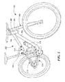
- FIG. 1 depicts an embodiment of a bicycle 100, such as a mountain bike for example, having a frame 200 that includes a front suspension system 300 and a rear suspension system 400.
- the rear suspension system 400 has a split shock format, also herein referred to as a split rear shock 410 (see FIG. 2 for example), in accordance with an embodiment of the invention, which is described in detail herein. From the teachings herein, however, it will also be appreciated that the split shock format can also be implemented on the front suspension system 300.
- the frame members 200 include a head tube 202, a top tube 204, a down tube 206, a seat tube 208, seat stay tubes 210, and chain stay tubes 212, but it will be appreciated that other frame member configurations may be employed that could benefit from an embodiment of the invention disclosed herein.
- a lefty front tube 214 In the illustrated embodiment of FIG. 1 , and pivotally coupled to the head tube 202, is a lefty front tube 214. Alternatively, front fork tubes may be used in place of the lefty front tube 214.
- FIG. 2 depicts a bicycle frame 200 similar to that depicted in FIG. 1 having a split rear shock 410 , where the top tube 204 has a front top tube 204.2 and a rear top tube 204.4.
- FIG. 3 depicts the bicycle frame 200 of FIG. 2 with a portion of the front top tube 204.2 cut away to illustrate placement of portions of the split rear shock 410 within the top tube 204 in accordance with an embodiment of the invention, and as described in detail herein.
- the split rear shock 410 has a first portion 412 disposed external of the top tube 204, and a second portion 414 disposed internal to the top tube 204, and more specifically in an embodiment disposed internal of the front top tube 204.2.
- the second portion 414 of the split rear shock 410 is fully integrated into the front top tube 204.2 of the frame 200, and disposed in line with the first portion 412 of the split rear shock 410 to provide an uncluttered aesthetic.
- the split rear shock 410 is disposed in line with the seat stay tubes 210, with the first portion 412 being coupled to the seat stay tubes 210 via a coupling 120, which in turn is coupled to the seat tube 208 via a pivotable swing arm 130.
- FIG. 4 depicts first 412 and second 414 portions of the split rear shock 410 coupled in fluid communication with each other via a flexible hose 416. While the term flexible hose is used herein, it will be appreciated that a rigid or semirigid fluid coupling may also be employed without detracting from the scope of the invention.
- a key distinction here over other bicycle shock absorber art is that the split rear shock format employs a first outer portion 412 that includes a shock absorber (an air spring, a rebound damping circuit, a compression damping circuit, or any combination thereof) (See FIGS.
- first and second portions 412, 414 are coupled in fluid communication with each other via the flexible hose 416.
- first outer portion 412 is disposed outside of the top tube 204
- second inner portion 414 is disposed within the top tube 204 (more specifically in an embodiment within the front top tube 204.2) of the bicycle frame 200.
- the split shock format maximizes the space between the frame members, such as the top tube 204, the down tube 206 and the seat tube 208, for at least two water bottles or other accessories, generally herein referred to by reference numeral 110, which creates a visually uncluttered look for the bicycle 100.
- FIGS. 5 and 6A-E depict the split rear shock 410 of FIG. 4 in more detail.
- a valve assembly 420 includes a rotary lock-out valve 422, a bi-stable REMA 424, a blow-off valve 426, and a reservoir 428.
- a compressible air chamber 430 within the valve/reservoir unit 420 accommodates ebb and flow of shock absorbing fluid.
- the compressible air chamber 430 is a bladder that surrounds the valve assembly 420 internal of the valve housing. In another embodiment (see FIG.
- the compressible air chamber is disposed in the housing of the reservoir 428 and has a piston 464 that separates the hydraulic chamber (left side of piston 464) from the air chamber (right side of piston 464) in a manner known in the art.
- Electrical wires 432 connect to the REMA 424, sensors, such as an accelerometer, and a power supply, disposed on or within the frame 200, for actuation thereof (discussed further below with reference to FIG. 8 for example).
- FIG. 6A-6E an embodiment of the split shock 410 is depicted with various details illustrated in expanded view, such as Detail 6B illustrated in the expanded view of FIG. 6B , Detail 6C illustrated in the expanded view of FIG. 6C , and Detail 6D illustrated in the expanded view of FIG. 6D .
- FIG. 6A depicts a split shock 410 similar to that of FIGS.
- FIG. 6B depicts an expanded view of an embodiment of the compression/valve unit 414
- FIG. 6C depicts a further expanded view of an embodiment of a compression damping valve 436
- FIG. 6D depicts a further expanded view of the lock-out valve 422 connected to and actuatable by the REMA 424; and, FIG.
- FIG. 6E depicts an expanded view of the valve 420 illustrating the REMA 424 and the lock-out valve 422 as a unit.
- An embodiment uses the bi-stable REMA 424 immersed inside the oil of the hydraulic damper unit 410 to either allow flow or prohibit flow, hence the term bi-stable, by actuating the lock-out valve 422.
- the response time of the actuator 424 is such that the valve 420, or more specifically the lock-out valve 422, opens and allows flow of hydraulic fluid before a rider of the bicycle 100 can perceive that a bump was encountered, where the bump is sensed via an accelerometer disposed on or within the frame 200 for example.
- the valve 420 could have other damping features integrated within the housing.
- valve 420 could be used in either the rear suspension system 400 of a bicycle 100 or the front suspension system 300.
- the lock-out valve 422 is arranged such that oil flows first through the lock-out valve 422, then through the compression damping valve 436 during a compression stroke.
- compression damping adjusters 438 (commonly known as low-speed compression adjusters, high-speed compression adjusters, and lock-out threshold adjusters) to be easily employed such that they do not have to pass through or around the valve 420, which greatly reduces complexity.
- the compression damping valve 436 is made small enough so that the power supply wires 432 to the REMA 424 may pass around the outside of the compression damping valve 436 and other internal components 440. This prevents the compression damping valve 436 from having to be rotationally aligned (or “clocked") to the REMA 424 to allow the wires 432 to pass through the compression damping valve 436, and it also negates the need to seal the wires 432 that would otherwise need to pass through the compression damping valve 436.
- the shock 412 incorporates an air spring (+ve/-ve chambers) and a rebound damping circuit, referred to generally by reference number 460, and a rebound damping and air pressure adjustment 462.
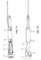
- FIGS. 7A and 7B depict primarily the second inner portion 414 of the split rear shock 410.
- Straps 442 connect the valve/reservoir unit 420, 428 to the first outer portion 412 of the split rear shock 410 (illustrated in FIGS. 7A and 7B as only the end of the shock 410) by a bolt 444 that prevents axial movement (compression/tension) of the flexible hose 416.
- Bosses 446 on the valve/reservoir unit 420, 428 extend below and allow the valve/reservoir unit 420, 428 to be bolted to the inside of the top tube 204.
- the valve/reservoir unit 420, 428 may be bolted to the top tube 204 in such a manner as to thermally connect the two structures together thereby enabling the aluminum top tube 204 to be used as a heat sink to cool the shock absorber 410. It is contemplated that cooling of the shock absorber 410 can be improved by as much as 500% over an arrangement where the top tube 204 is not aluminum and/or the valve/reservoir unit 420, 428 is not bolted to the top tube 204.
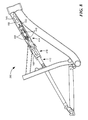
- FIGS. 8 and 9 depict the bicycle frame 200, or a portion thereof, similar to that depicted in FIG. 3 , where a rubber seal 448, or other suitable sealing material, is disposed around the valve assembly 420 of the second portion 414 of the split rear shock 410 between the valve assembly 420 and an internal surface 450 of the top tube 204 to prevent dirt and/or water from getting inside the bicycle frame 200, particularly in wet weather or when washing the bicycle 100.
- the rubber seal 448 also serves to hold the valve assembly 420 in the frame 200.
- the rubber seal 448 and top tube 204 may also have a small leak path 452 to drain any water that enters the top tube 204 from another location.
- the second inner portion 414 of the shock 410 includes operably connected thereto electronics 140, such as a wireless data connection, a motor control, and/or an accelerometer, for example, and/or a battery 150, rechargeable or not, to power the system (the electronics 140 and the REMA 424 for example) via the electrical wires 432.
- the accelerometer referred to generally herein by reference numeral 140, may be disposed on or within the front top tube 204.2, as depicted in FIG. 8 for example, or anywhere else on or within a member of the frame 200 or any other portion of the bicycle 100, such as the front suspension system 300 for example.
- the shock absorber 410 also includes a power generation device 160 operably coupled, via wires for example, to recharge the battery 150, either by an electro mechanical, a hydraulic electro mechanical, or a piezo resistive device and associated method, for example.
- the power generation device 160 is responsive to relative motion between portions of the shock absorber 410 to create a voltage suitable for recharging the battery 150.
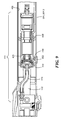
- FIG. 9 an enlarged view of the second portion 414 of the split rear shock 410 depicted in FIG. 8 is further depicted showing the rubber seal 448 disposed around the valve assembly 420 between the valve assembly 420 and an internal surface 450 of the top tube 204 to prevent dirt from getting inside the bicycle frame 200. Also shown is an optional fastener 454 to provide additional securement of the valve assembly 420 to the bicycle frame 200. Also shown is one side (far side) of a two-sided strap 442, or bracket, securely mounted between the first and second portions 412, 414 of the split rear shock 410.
- the strap/bracket 442 takes the force of the flexible hose 416 between the first and second portions 412, 414 and prevents undue stress being imparted to the flexible hose 416, and in conjunction with the rubber seal 448 may be used to secure the second portion 414 to the frame 200 without the need for additional fasteners being required.
- FIGS. 10A and 10 B depict a cross section view and a perspective view, respectively, of the strap/bracket 442 of FIG. 9 connecting the second portion 414 with the first portion 412.
- a mounting pin 456, or other suitable shock absorber hardware is disposed between the strap/bracket 442 and the first portion 412 and includes shouldered ends 458 that serve to pinch the strap/bracket 442 between the mounting pin 456 and the bicycle frame 200 at the mounting point, which assists in stabilizing the valve assembly 420.
- the mounting bolt 444 serves to secure the strap/bracket 442 to the mounting pin 456 and frame 200.
- FIG. 11 depicts a frame 200 similar to that of FIGS. 1-3 , but where the second inner portion 414 of the shock absorber 410 is depicted in alternative locations within the frame 200.
- the second inner portion 414 is disposed at location "A" inside the rear top tube 204.4, and in a second embodiment, the second inner portion 414 is disposed at location "B" inside the front top tube 204.2 similar to that of FIG. 3 .
- the second inner portion 414 comprises a reservoir unit of a piggyback shock, where in the first embodiment the piggyback reservoir unit is disposed at location "A", and in the second embodiment the piggyback reservoir unit is disposed at location "B".
- the piggyback shock (herein referred to generally by reference numeral 410 with reference to FIG. 11 ) may have two reservoir units, a first reservoir unit disposed at location "A" and a second reservoir unit disposed at location "B".
- the first outer portion 412 of the embodiment of FIG. 11 comprises the shock body of the piggyback shock that is fluidly coupled to the reservoir unit(s) in a manner known in the art, or via the flexible hose 416.
Landscapes
- Engineering & Computer Science (AREA)
- Mechanical Engineering (AREA)
- General Engineering & Computer Science (AREA)
- Axle Suspensions And Sidecars For Cycles (AREA)
Applications Claiming Priority (2)
| Application Number | Priority Date | Filing Date | Title |
|---|---|---|---|
| US201462037663P | 2014-08-15 | 2014-08-15 | |
| US14/825,490 US9527545B2 (en) | 2014-08-15 | 2015-08-13 | Bicycle suspension system |
Publications (2)
| Publication Number | Publication Date |
|---|---|
| EP2985489A2 true EP2985489A2 (fr) | 2016-02-17 |
| EP2985489A3 EP2985489A3 (fr) | 2016-05-18 |
Family
ID=53836018
Family Applications (1)
| Application Number | Title | Priority Date | Filing Date |
|---|---|---|---|
| EP15181158.5A Withdrawn EP2985489A3 (fr) | 2014-08-15 | 2015-08-14 | Système de suspension de bicyclette |
Country Status (2)
| Country | Link |
|---|---|
| US (1) | US9527545B2 (fr) |
| EP (1) | EP2985489A3 (fr) |
Cited By (1)
| Publication number | Priority date | Publication date | Assignee | Title |
|---|---|---|---|---|
| EP3501959A1 (fr) * | 2017-12-21 | 2019-06-26 | Trek Bicycle Corporation | Cadre de bicyclette avec dispositif d'amortissement interne |
Families Citing this family (6)
| Publication number | Priority date | Publication date | Assignee | Title |
|---|---|---|---|---|
| US20160153515A1 (en) * | 2014-12-02 | 2016-06-02 | Cycling Sports Group, Inc. | Valve Assembly For Bicycle Suspension System |
| US10336397B2 (en) | 2014-12-29 | 2019-07-02 | Peter Tristan Ridet | System and method for dynamic motorcycle frame |
| US10689056B2 (en) * | 2015-04-14 | 2020-06-23 | Matthew Hendey | Apparatus, systems, and methods for preventing migration of contaminants within tubing of a frame |
| US10919592B2 (en) * | 2018-04-06 | 2021-02-16 | Specialized Bicycle Components, Inc. | Bicycle with compliant seat post interface |
| EP3587234B1 (fr) * | 2018-06-22 | 2021-03-10 | Orbea, S. Coop. | Cadre de bicyclette à absorbeur de chocs intégré |
| US11724769B2 (en) | 2019-12-17 | 2023-08-15 | Sram, Llc | Bicycle suspension components and electronic control devices |
Citations (1)
| Publication number | Priority date | Publication date | Assignee | Title |
|---|---|---|---|---|
| US8459418B2 (en) | 2001-07-02 | 2013-06-11 | Fox Factory, Inc. | Bicycle fork having lock-out, blow-off, and adjustable blow-off threshold |
Family Cites Families (15)
| Publication number | Priority date | Publication date | Assignee | Title |
|---|---|---|---|---|
| US644957A (en) * | 1899-09-05 | 1900-03-06 | Gurdon H Williams | Spring-frame for bicycles. |
| US1068583A (en) * | 1912-11-18 | 1913-07-29 | William S Harley | Frame for motor-cycles or like vehicles. |
| US1071892A (en) * | 1913-03-17 | 1913-09-02 | Frederick Diepenhorst | Cycle-frame. |
| JPS5140336B2 (fr) | 1972-04-05 | 1976-11-02 | ||
| JPS5016247A (fr) * | 1973-06-18 | 1975-02-20 | ||
| US4679811A (en) | 1986-06-26 | 1987-07-14 | Shuler Jerry N | Bicycle rear suspension system |
| GB8921962D0 (en) * | 1989-09-28 | 1989-11-15 | Browning Michael R S | Variable suspension system |
| US5409248A (en) * | 1991-08-12 | 1995-04-25 | Williams; Richard L. | Bicycle suspension |
| US5772228A (en) * | 1995-09-08 | 1998-06-30 | Beyond Beryllium Fabrications | Integrated rear suspension for a bicycle frame |
| IT1308730B1 (it) | 1999-06-16 | 2002-01-10 | Adriano Rolle | Telaio per bicicletta con sospensione per la ruota posteriore |
| DE10066061B4 (de) * | 2000-03-20 | 2005-09-01 | Stephan Albrecht | Fahrrad-Verstelleinrichtung |
| DE20005224U1 (de) | 2000-03-20 | 2001-07-05 | Albrecht, Stephan, 83627 Warngau | Fahrrad |
| US7722069B2 (en) * | 2008-06-06 | 2010-05-25 | Shimano Inc. | Bicycle suspension system |
| TWM378163U (en) * | 2009-09-21 | 2010-04-11 | Shimano Kk | Electronic control apparatus for a height adjustable seat post assembly of a bicycle |
| US8256787B2 (en) * | 2009-10-08 | 2012-09-04 | Shimano Inc. | Adjustable bicycle suspension system |
-
2015
- 2015-08-13 US US14/825,490 patent/US9527545B2/en active Active
- 2015-08-14 EP EP15181158.5A patent/EP2985489A3/fr not_active Withdrawn
Patent Citations (1)
| Publication number | Priority date | Publication date | Assignee | Title |
|---|---|---|---|---|
| US8459418B2 (en) | 2001-07-02 | 2013-06-11 | Fox Factory, Inc. | Bicycle fork having lock-out, blow-off, and adjustable blow-off threshold |
Cited By (1)
| Publication number | Priority date | Publication date | Assignee | Title |
|---|---|---|---|---|
| EP3501959A1 (fr) * | 2017-12-21 | 2019-06-26 | Trek Bicycle Corporation | Cadre de bicyclette avec dispositif d'amortissement interne |
Also Published As
| Publication number | Publication date |
|---|---|
| US20160046346A1 (en) | 2016-02-18 |
| US9527545B2 (en) | 2016-12-27 |
| EP2985489A3 (fr) | 2016-05-18 |
Similar Documents
| Publication | Publication Date | Title |
|---|---|---|
| US9527545B2 (en) | Bicycle suspension system | |
| US20160153515A1 (en) | Valve Assembly For Bicycle Suspension System | |
| US8770594B2 (en) | Electric suspension device and motorcycle | |
| CN103825402B (zh) | 用于车辆的悬挂系统的能量再生装置 | |
| US9022157B2 (en) | Motorcycle | |
| EP2123933A2 (fr) | Amortisseur et véhicule | |
| US20120146339A1 (en) | Energy regeneration device of suspension system for vehicle | |
| US20130118847A1 (en) | Multi-mode shock assembly | |
| CN103909825B (zh) | 用于车辆的悬架系统的能量再生设备 | |
| KR20060055539A (ko) | 충격 흡수장치 어셈블리 | |
| TWI752254B (zh) | 液壓操作裝置 | |
| AU2015355064B2 (en) | Shock absorbers | |
| EP3416879B1 (fr) | Ensemble monture de guidon | |
| EP1234760A2 (fr) | Blocage automatique de suspension pour bicyclettes | |
| US20150137469A1 (en) | Scooter having position recovery and shock-absorbing functions | |
| CN217207477U (zh) | 一种摩托车气动悬挂结构 | |
| JP6363414B2 (ja) | 緩衝器 | |
| TWI541162B (zh) | Suspension device | |
| TWI830843B (zh) | 機車前懸吊系統及包括其之機車 | |
| JP2005231603A (ja) | 二輪車用懸架装置 | |
| JP5150333B2 (ja) | 二輪車のフロントフォーク | |
| JP4394933B2 (ja) | 自動二輪車等の懸架装置 | |
| JP4579844B2 (ja) | フロントフォーク | |
| US20080169163A1 (en) | Harmonic dampener | |
| JP2004232705A (ja) | 自動二輪車等のフロントフォーク装置 |
Legal Events
| Date | Code | Title | Description |
|---|---|---|---|
| PUAI | Public reference made under article 153(3) epc to a published international application that has entered the european phase |
Free format text: ORIGINAL CODE: 0009012 |
|
| AK | Designated contracting states |
Kind code of ref document: A2 Designated state(s): AL AT BE BG CH CY CZ DE DK EE ES FI FR GB GR HR HU IE IS IT LI LT LU LV MC MK MT NL NO PL PT RO RS SE SI SK SM TR |
|
| AX | Request for extension of the european patent |
Extension state: BA ME |
|
| PUAL | Search report despatched |
Free format text: ORIGINAL CODE: 0009013 |
|
| AK | Designated contracting states |
Kind code of ref document: A3 Designated state(s): AL AT BE BG CH CY CZ DE DK EE ES FI FR GB GR HR HU IE IS IT LI LT LU LV MC MK MT NL NO PL PT RO RS SE SI SK SM TR |
|
| AX | Request for extension of the european patent |
Extension state: BA ME |
|
| RIC1 | Information provided on ipc code assigned before grant |
Ipc: F16F 9/32 20060101AFI20160408BHEP Ipc: B62K 25/28 20060101ALI20160408BHEP Ipc: B62K 25/10 20060101ALI20160408BHEP Ipc: F16F 9/06 20060101ALI20160408BHEP Ipc: B62K 25/30 20060101ALI20160408BHEP |
|
| 17P | Request for examination filed |
Effective date: 20161101 |
|
| RBV | Designated contracting states (corrected) |
Designated state(s): AL AT BE BG CH CY CZ DE DK EE ES FI FR GB GR HR HU IE IS IT LI LT LU LV MC MK MT NL NO PL PT RO RS SE SI SK SM TR |
|
| GRAP | Despatch of communication of intention to grant a patent |
Free format text: ORIGINAL CODE: EPIDOSNIGR1 |
|
| INTG | Intention to grant announced |
Effective date: 20171107 |
|
| STAA | Information on the status of an ep patent application or granted ep patent |
Free format text: STATUS: THE APPLICATION IS DEEMED TO BE WITHDRAWN |
|
| 18D | Application deemed to be withdrawn |
Effective date: 20180301 |