EP2988005A1 - Montageanordnung für einen flügel - Google Patents
Montageanordnung für einen flügel Download PDFInfo
- Publication number
- EP2988005A1 EP2988005A1 EP15179621.6A EP15179621A EP2988005A1 EP 2988005 A1 EP2988005 A1 EP 2988005A1 EP 15179621 A EP15179621 A EP 15179621A EP 2988005 A1 EP2988005 A1 EP 2988005A1
- Authority
- EP
- European Patent Office
- Prior art keywords
- ridge
- mounting arrangement
- arrangement according
- root
- mounting
- Prior art date
- Legal status (The legal status is an assumption and is not a legal conclusion. Google has not performed a legal analysis and makes no representation as to the accuracy of the status listed.)
- Granted
Links
Images
Classifications
-
- F—MECHANICAL ENGINEERING; LIGHTING; HEATING; WEAPONS; BLASTING
- F01—MACHINES OR ENGINES IN GENERAL; ENGINE PLANTS IN GENERAL; STEAM ENGINES
- F01D—NON-POSITIVE DISPLACEMENT MACHINES OR ENGINES, e.g. STEAM TURBINES
- F01D9/00—Stators
- F01D9/02—Nozzles; Nozzle boxes; Stator blades; Guide conduits, e.g. individual nozzles
- F01D9/04—Nozzles; Nozzle boxes; Stator blades; Guide conduits, e.g. individual nozzles forming ring or sector
- F01D9/042—Nozzles; Nozzle boxes; Stator blades; Guide conduits, e.g. individual nozzles forming ring or sector fixing blades to stators
-
- F—MECHANICAL ENGINEERING; LIGHTING; HEATING; WEAPONS; BLASTING
- F01—MACHINES OR ENGINES IN GENERAL; ENGINE PLANTS IN GENERAL; STEAM ENGINES
- F01D—NON-POSITIVE DISPLACEMENT MACHINES OR ENGINES, e.g. STEAM TURBINES
- F01D5/00—Blades; Blade-carrying members; Heating, heat-insulating, cooling or antivibration means on the blades or the members
- F01D5/12—Blades
- F01D5/28—Selecting particular materials; Particular measures relating thereto; Measures against erosion or corrosion
- F01D5/282—Selecting composite materials, e.g. blades with reinforcing filaments
-
- F—MECHANICAL ENGINEERING; LIGHTING; HEATING; WEAPONS; BLASTING
- F01—MACHINES OR ENGINES IN GENERAL; ENGINE PLANTS IN GENERAL; STEAM ENGINES
- F01D—NON-POSITIVE DISPLACEMENT MACHINES OR ENGINES, e.g. STEAM TURBINES
- F01D5/00—Blades; Blade-carrying members; Heating, heat-insulating, cooling or antivibration means on the blades or the members
- F01D5/12—Blades
- F01D5/28—Selecting particular materials; Particular measures relating thereto; Measures against erosion or corrosion
- F01D5/284—Selection of ceramic materials
-
- F—MECHANICAL ENGINEERING; LIGHTING; HEATING; WEAPONS; BLASTING
- F01—MACHINES OR ENGINES IN GENERAL; ENGINE PLANTS IN GENERAL; STEAM ENGINES
- F01D—NON-POSITIVE DISPLACEMENT MACHINES OR ENGINES, e.g. STEAM TURBINES
- F01D9/00—Stators
- F01D9/02—Nozzles; Nozzle boxes; Stator blades; Guide conduits, e.g. individual nozzles
- F01D9/04—Nozzles; Nozzle boxes; Stator blades; Guide conduits, e.g. individual nozzles forming ring or sector
- F01D9/041—Nozzles; Nozzle boxes; Stator blades; Guide conduits, e.g. individual nozzles forming ring or sector using blades
-
- F—MECHANICAL ENGINEERING; LIGHTING; HEATING; WEAPONS; BLASTING
- F04—POSITIVE - DISPLACEMENT MACHINES FOR LIQUIDS; PUMPS FOR LIQUIDS OR ELASTIC FLUIDS
- F04D—NON-POSITIVE-DISPLACEMENT PUMPS
- F04D29/00—Details, component parts, or accessories
- F04D29/02—Selection of particular materials
- F04D29/023—Selection of particular materials especially adapted for elastic fluid pumps
-
- F—MECHANICAL ENGINEERING; LIGHTING; HEATING; WEAPONS; BLASTING
- F04—POSITIVE - DISPLACEMENT MACHINES FOR LIQUIDS; PUMPS FOR LIQUIDS OR ELASTIC FLUIDS
- F04D—NON-POSITIVE-DISPLACEMENT PUMPS
- F04D29/00—Details, component parts, or accessories
- F04D29/40—Casings; Connections of working fluid
- F04D29/52—Casings; Connections of working fluid for axial pumps
- F04D29/54—Fluid-guiding means, e.g. diffusers
- F04D29/541—Specially adapted for elastic fluid pumps
- F04D29/542—Bladed diffusers
-
- F—MECHANICAL ENGINEERING; LIGHTING; HEATING; WEAPONS; BLASTING
- F04—POSITIVE - DISPLACEMENT MACHINES FOR LIQUIDS; PUMPS FOR LIQUIDS OR ELASTIC FLUIDS
- F04D—NON-POSITIVE-DISPLACEMENT PUMPS
- F04D29/00—Details, component parts, or accessories
- F04D29/60—Mounting; Assembling; Disassembling
- F04D29/64—Mounting; Assembling; Disassembling of axial pumps
- F04D29/644—Mounting; Assembling; Disassembling of axial pumps especially adapted for elastic fluid pumps
-
- F—MECHANICAL ENGINEERING; LIGHTING; HEATING; WEAPONS; BLASTING
- F05—INDEXING SCHEMES RELATING TO ENGINES OR PUMPS IN VARIOUS SUBCLASSES OF CLASSES F01-F04
- F05D—INDEXING SCHEME FOR ASPECTS RELATING TO NON-POSITIVE-DISPLACEMENT MACHINES OR ENGINES, GAS-TURBINES OR JET-PROPULSION PLANTS
- F05D2220/00—Application
- F05D2220/30—Application in turbines
- F05D2220/32—Application in turbines in gas turbines
-
- F—MECHANICAL ENGINEERING; LIGHTING; HEATING; WEAPONS; BLASTING
- F05—INDEXING SCHEMES RELATING TO ENGINES OR PUMPS IN VARIOUS SUBCLASSES OF CLASSES F01-F04
- F05D—INDEXING SCHEME FOR ASPECTS RELATING TO NON-POSITIVE-DISPLACEMENT MACHINES OR ENGINES, GAS-TURBINES OR JET-PROPULSION PLANTS
- F05D2230/00—Manufacture
- F05D2230/20—Manufacture essentially without removing material
- F05D2230/23—Manufacture essentially without removing material by permanently joining parts together
-
- F—MECHANICAL ENGINEERING; LIGHTING; HEATING; WEAPONS; BLASTING
- F05—INDEXING SCHEMES RELATING TO ENGINES OR PUMPS IN VARIOUS SUBCLASSES OF CLASSES F01-F04
- F05D—INDEXING SCHEME FOR ASPECTS RELATING TO NON-POSITIVE-DISPLACEMENT MACHINES OR ENGINES, GAS-TURBINES OR JET-PROPULSION PLANTS
- F05D2240/00—Components
- F05D2240/10—Stators
- F05D2240/12—Fluid guiding means, e.g. vanes
- F05D2240/125—Fluid guiding means, e.g. vanes related to the tip of a stator vane
-
- F—MECHANICAL ENGINEERING; LIGHTING; HEATING; WEAPONS; BLASTING
- F05—INDEXING SCHEMES RELATING TO ENGINES OR PUMPS IN VARIOUS SUBCLASSES OF CLASSES F01-F04
- F05D—INDEXING SCHEME FOR ASPECTS RELATING TO NON-POSITIVE-DISPLACEMENT MACHINES OR ENGINES, GAS-TURBINES OR JET-PROPULSION PLANTS
- F05D2240/00—Components
- F05D2240/80—Platforms for stationary or moving blades
-
- F—MECHANICAL ENGINEERING; LIGHTING; HEATING; WEAPONS; BLASTING
- F05—INDEXING SCHEMES RELATING TO ENGINES OR PUMPS IN VARIOUS SUBCLASSES OF CLASSES F01-F04
- F05D—INDEXING SCHEME FOR ASPECTS RELATING TO NON-POSITIVE-DISPLACEMENT MACHINES OR ENGINES, GAS-TURBINES OR JET-PROPULSION PLANTS
- F05D2250/00—Geometry
- F05D2250/10—Two-dimensional
- F05D2250/18—Two-dimensional patterned
- F05D2250/181—Two-dimensional patterned ridged
-
- F—MECHANICAL ENGINEERING; LIGHTING; HEATING; WEAPONS; BLASTING
- F05—INDEXING SCHEMES RELATING TO ENGINES OR PUMPS IN VARIOUS SUBCLASSES OF CLASSES F01-F04
- F05D—INDEXING SCHEME FOR ASPECTS RELATING TO NON-POSITIVE-DISPLACEMENT MACHINES OR ENGINES, GAS-TURBINES OR JET-PROPULSION PLANTS
- F05D2300/00—Materials; Properties thereof
- F05D2300/20—Oxide or non-oxide ceramics
-
- F—MECHANICAL ENGINEERING; LIGHTING; HEATING; WEAPONS; BLASTING
- F05—INDEXING SCHEMES RELATING TO ENGINES OR PUMPS IN VARIOUS SUBCLASSES OF CLASSES F01-F04
- F05D—INDEXING SCHEME FOR ASPECTS RELATING TO NON-POSITIVE-DISPLACEMENT MACHINES OR ENGINES, GAS-TURBINES OR JET-PROPULSION PLANTS
- F05D2300/00—Materials; Properties thereof
- F05D2300/20—Oxide or non-oxide ceramics
- F05D2300/21—Oxide ceramics
- F05D2300/2102—Glass
-
- F—MECHANICAL ENGINEERING; LIGHTING; HEATING; WEAPONS; BLASTING
- F05—INDEXING SCHEMES RELATING TO ENGINES OR PUMPS IN VARIOUS SUBCLASSES OF CLASSES F01-F04
- F05D—INDEXING SCHEME FOR ASPECTS RELATING TO NON-POSITIVE-DISPLACEMENT MACHINES OR ENGINES, GAS-TURBINES OR JET-PROPULSION PLANTS
- F05D2300/00—Materials; Properties thereof
- F05D2300/20—Oxide or non-oxide ceramics
- F05D2300/22—Non-oxide ceramics
- F05D2300/224—Carbon, e.g. graphite
-
- F—MECHANICAL ENGINEERING; LIGHTING; HEATING; WEAPONS; BLASTING
- F05—INDEXING SCHEMES RELATING TO ENGINES OR PUMPS IN VARIOUS SUBCLASSES OF CLASSES F01-F04
- F05D—INDEXING SCHEME FOR ASPECTS RELATING TO NON-POSITIVE-DISPLACEMENT MACHINES OR ENGINES, GAS-TURBINES OR JET-PROPULSION PLANTS
- F05D2300/00—Materials; Properties thereof
- F05D2300/40—Organic materials
- F05D2300/43—Synthetic polymers, e.g. plastics; Rubber
-
- F—MECHANICAL ENGINEERING; LIGHTING; HEATING; WEAPONS; BLASTING
- F05—INDEXING SCHEMES RELATING TO ENGINES OR PUMPS IN VARIOUS SUBCLASSES OF CLASSES F01-F04
- F05D—INDEXING SCHEME FOR ASPECTS RELATING TO NON-POSITIVE-DISPLACEMENT MACHINES OR ENGINES, GAS-TURBINES OR JET-PROPULSION PLANTS
- F05D2300/00—Materials; Properties thereof
- F05D2300/60—Properties or characteristics given to material by treatment or manufacturing
- F05D2300/603—Composites; e.g. fibre-reinforced
-
- Y—GENERAL TAGGING OF NEW TECHNOLOGICAL DEVELOPMENTS; GENERAL TAGGING OF CROSS-SECTIONAL TECHNOLOGIES SPANNING OVER SEVERAL SECTIONS OF THE IPC; TECHNICAL SUBJECTS COVERED BY FORMER USPC CROSS-REFERENCE ART COLLECTIONS [XRACs] AND DIGESTS
- Y02—TECHNOLOGIES OR APPLICATIONS FOR MITIGATION OR ADAPTATION AGAINST CLIMATE CHANGE
- Y02T—CLIMATE CHANGE MITIGATION TECHNOLOGIES RELATED TO TRANSPORTATION
- Y02T50/00—Aeronautics or air transport
- Y02T50/60—Efficient propulsion technologies, e.g. for aircraft
Definitions
- the present invention relates to an aerofoil body such as a blade or guide vane for a gas turbine engine and a mounting arrangement for such an aerofoil body.
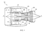
- a ducted fan gas turbine engine is generally indicated at 10 and has a principal and rotational axis X-X.
- the engine comprises, in axial flow series, an air intake 11, a propulsive fan 12, an intermediate pressure compressor 13, a high-pressure compressor 14, combustion equipment 15, a high-pressure turbine 16, an intermediate pressure turbine 17, a low-pressure turbine 18 and a core engine exhaust nozzle 19.
- a nacelle 21 generally surrounds the engine 10 and defines the intake 11, a bypass duct 22 and a bypass exhaust nozzle 23.
- air entering the intake 11 is accelerated by the fan 12 to produce two air flows: a first air flow A into the intermediate pressure compressor 13 and a second air flow B which passes through the bypass duct 22 to provide propulsive thrust.
- the intermediate pressure compressor 13 compresses the air flow A directed into it before delivering that air to the high pressure compressor 14 where further compression takes place.
- the compressed air exhausted from the high-pressure compressor 14 is directed into the combustion equipment 15 where it is mixed with fuel and the mixture combusted.
- the resultant hot combustion products then expand through, and thereby drive the high, intermediate and low-pressure turbines 16, 17, 18 before being exhausted through the nozzle 19 to provide additional propulsive thrust.
- the high, intermediate and low-pressure turbines respectively drive the high and intermediate pressure compressors 14, 13 and the fan 12 by suitable interconnecting shafts.
- Each of the high and intermediate compressors 14, 13 comprises a number of alternating series of circumferentially-spaced rotating blades and circumferentially-spaced static vanes.
- the rotating blades act to compress the air flow A whilst the static vanes act to direct the compressed air onto the next series of rotating blades.
- Outlet guide vanes (OGVs) at the exit of the high pressure compressor 14 act to optimise (straighten) the direction of the air flow A into the combustion equipment 15.
- the OGVs are mounted between an inner ring and an outer ring, the vanes and rings typically being formed of homogenous metallic or reinforced metallic/non-metallic material.
- OGV assemblies formed of reinforced plastic material are preferable as they are lighter than metallic OGV assemblies.
- the vanes may affixed to the inner and outer rings using either dove-tail joints or "L-angle" joints. In both cases, the vanes are formed with the reinforcing fibres aligned from the root to the tip of the vane.
- the reinforcing fibres When a dovetail joint is used to affix the vane to the rings, the reinforcing fibres are splayed towards the root and/or tip of the vane and wedging fibres are introduced between the splayed fibres to form the necessary wedge-shaped root/tip portion.
- the reinforcing fibres When an L-angle joint is used to affix the vane to rings, the reinforcing fibres are angled through 90 degrees.
- the present invention provides an aerofoil body comprising a root portion and a tip portion, each having a pressure surface and a suction surface, wherein the pressure surface and suction surface of the root and/or tip portion each comprise a respective ridge portion, each ridge portion having an inclined first face and an oppositely inclined second face.
- reaction of tension, compression and bending loads applied to the aerofoil body is improved because the forces can be better transferred to the surrounding structures supporting the aerofoil body.
- reaction of compressive forces as well as shearing and bending forces is accommodated well.
- the compressive forces are reacted by the inclined faces opposite to those normally provided on a dovetail wedge and the reaction of shearing and bending forces are improved because there are two faces on each of the pressure/suctions surfaces for moment reaction.
- the pressure surface and suction surface of both the root and tip portion each comprise a respective ridge portion, each ridge portion having a respective inclined first face and a respective oppositely inclined second face.
- first and second faces of each ridge portion join one another at the apex of the respective ridge portion.
- the height of the ridge portion from the respective pressure/suction surface is between 10 and 50% of the spacing between the pressure and suction surfaces of the root/tip portion.
- first and second faces of each ridge portion are oppositely and equally inclined.
- first face and/or second face of each ridge portion is/are planar.
- the ridge portion is shaped as a triangular prism. Since the ridge portions are provided on both the pressure and suction surfaces, the root/tip portion has a thickened portion formed of the opposing ridge portions, the thickened portion having a substantially diamond/kite-shaped cross-sectional profile (at right angles to the pressure/suction surfaces of the aerofoil body).
- first face and/or second faces of each ridge portion is/are curved e.g. the first and/or second faces of each ridge portion is/are convex surfaces.
- the ridge portion is shaped as a semi-circular prism. Since the ridge portions are provided on both the pressure and suction surfaces, the root/tip portion has a thickened portion formed of the opposing ridge portions, the thickened portion having a substantially circular cross-sectional profile (at right angles to the pressure/suction surfaces of the aerofoil body).
- the ridge portions are spaced from the end of the root/tip portion. This further improves the moment reaction for bending/shearing forces.
- the aerofoil body is a blade e.g. a blade for a fan, compressor or turbine in a gas turbine engine.
- the aerofoil body is a vane e.g. a guide vane such as an outlet guide vane for a compressor in a gas turbine engine.
- the aerofoil body is formed of an organic matrix composite (OMC) (e.g. fibre reinforced plastic material) or a metal matrix composite (MMC).
- OMC organic matrix composite
- MMC metal matrix composite
- the organic matrix may be a thermoplastic polymer matrix.
- the fibres e.g. glass, ceramic or carbon fibres in the reinforced plastic material used to manufacture the aerofoil body are substantially aligned in the aerofoil body from the root to tip portion and are splayed in the vicinity of the ridge portions with wedging plies inserted between the splayed fibres.
- the present invention provides a mounting arrangement for mounting an aerofoil body on an annular support, the mounting arrangement comprising:
- a mounting bracket having a central portion housing the ridge portions and perpendicularly extending flange portions (which can be affixed e.g. bolted, onto the inner or outer annular supports), shearing loads on the aerofoil body can be transferred to the central portion of the mounting bracket through the oppositely inclined faces of the ridge portion and subsequently through 90 degrees to the flange portions without requiring a thickening of the aerofoil body.
- the or each bracket may be said to have a wasted section that cooperates with the ridge portion of the tip or root.
- the central portion may be described as and/or may comprise such a wasted section.
- the mounting arrangement comprises two mounting brackets, one having a central portion housing the ridge portions on the root portion and one having a central portion housing the ridge portions on the tip portion.
- the at least one mounting bracket may be affixed e.g. bolted to the radially outer surface of the radially inner annular support or the radially inner surface of the radially outer annular support. Fairings may be provided to cover the fixings to improve aerodynamic efficiency.
- the mounting bracket may be affixed to the radially inner surface of the radially inner annular support or to the radially outer surface of the radially outer annular support with the aerofoil body extending through the radially inner/radially outer annular support. In this way, the fixings are kept out of the gas flow path.
- the mounting bracket(s) is/are formed of a sheet moulding compound (SMC) or an OMC e.g. from a glass, ceramic or carbon fibre-reinforced plastics material.
- SMC sheet moulding compound
- OMC organic-reinforced plastics material
- the fibres may be aligned in the central portion and then deflect through 90 degrees to extend along the flange portions.
- the mounting bracket(s) may be cured or moulded around the root/tip portion of the aerofoil body.
- the mounting bracket(s) may have web portions having an inclined surface extending from the central portion to the flange portions to reinforce the mounting bracket.
- the present invention provides a vane assembly comprising:
- the mounting brackets may be affixed e.g. bolted to the radially outer surface of the radially inner annular support and radially inner surface of the radially outer annular support. Fairings may be provided to cover the fixings to improve aerodynamic efficiency.
- the vane assembly comprises a plurality of circumferentially-spaced aerofoil assemblies each according to the second aspect.
- the present invention provides an axial compressor for a gas turbine engine having an aerofoil body according to the first aspect, a mounting arrangement according to the second aspect or a vane assembly according to the third aspect.
- the present invention provides a gas turbine engine having an aerofoil body according to the first aspect, a mounting arrangement according to the second aspect, a vane assembly according to the third aspect or an axial compressor according to the fourth aspect.
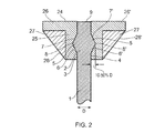
- Figure 2 shows an outlet guide vane assembly comprising an aerofoil body (vane) 1 comprising a root portion 2 and a tip portion (not shown).
- vane aerofoil body
- the root portion 2 has a pressure surface 3 and a suction surface 4. Each surface comprises a ridge portion 5, 5'. Each ridge portion 5, 5' comprises an inclined first face 6, 6' and an oppositely and equally inclined second face 7, 7'.
- each ridge portion 5, 5' is shaped as a triangular prism. Since ridge portions 5, 5' provided on both the pressure and suction surfaces 3, 4, the root portion 2 has a thickened portion formed of the opposing ridge portions 5, 5', the thickened portion having a substantially diamond/kite-shaped cross-sectional profile (at right angles to the pressure/suction surfaces 3, 4 of the aerofoil body 1).
- the height of the ridge portions 5, 5' i.e. distance from the apex 8, 8' to the respective pressure surface/suction surface 3, 4 is between 10 and 50% of the spacing D between the pressure and suction surfaces 3, 4 of the root portion 2.
- the ridge portions 5, 5' are spaced from the end 9 of the root portion 2.
- the aerofoil body (vane) 1 is formed of a fibre reinforced plastics material.
- the plastic matrix material may be a thermoplastic polymer.
- the fibres e.g. glass, ceramic or carbon fibres in the reinforced plastic material are substantially aligned in the aerofoil body 1 from the root portion 2 to tip portion and are splayed in the vicinity of the ridge portions 5, 5' with wedging plies inserted between the splayed fibres.
- the fibres may be provided in the form of a non-crimped fabric.
- a mounting bracket 24 formed of fibre-reinforced plastic is moulded around the root portion 2 and has a central portion 25 which surrounds the ridge portions 5.
- Two opposing flange portions 26, 26' extend perpendicularly from the central portion 25.
- the fibres in fibre reinforced plastic are aligned in the central portion 25 (parallel to the fibres in the aerofoil body 1) and then deflect through 90 degrees to extend along the flange portions 26, 26'.
- the mounting bracket 24 has web portions 27, 27' each having an inclined surface 28, 28' extending from the central portion 25 to the flange portions 26, 26' to reinforce the mounting bracket 24.
- the flange portions 26, 26' are affixed e.g. bolted to a radially inner annular support (not shown). It should be noted that the radially annular support will support a series of circumferentially-spaced aerofoil bodies (vanes) identical to that shown in Figure 2 .
- each aerofoil body 1 may have an identical structure to the root portion 2 and is retained within a respective second mounting bracket which is affixed to an outer annular support. Accordingly, Figure 2 may alternatively show a tip portion, with the same reference numerals applying to both the root portion and the tip portion.
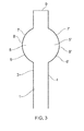
- FIG. 3 A second embodiment of an aerofoil body in shown in Figure 3 .
- the first face and second faces 6, 6', 7, 7' of each ridge portion 5, 5' are curved convex surfaces which meet at the apex 8, 8' such that the ridge portions 5, 5' are shaped as a semi-circular prism. Since ridge portions 5, 5' are provided on both the pressure and suction surfaces 3, 4, the root portion 2 having a thickened portion formed of the opposing ridge portions 5, 5', the thickened portion having a substantially circular cross-sectional profile (at right angles to the pressure/suction surfaces 3, 4 of the aerofoil body 1).
Landscapes
- Engineering & Computer Science (AREA)
- Mechanical Engineering (AREA)
- General Engineering & Computer Science (AREA)
- Chemical & Material Sciences (AREA)
- Materials Engineering (AREA)
- Ceramic Engineering (AREA)
- Composite Materials (AREA)
- Structures Of Non-Positive Displacement Pumps (AREA)
Applications Claiming Priority (1)
| Application Number | Priority Date | Filing Date | Title |
|---|---|---|---|
| GBGB1414587.4A GB201414587D0 (en) | 2014-08-18 | 2014-08-18 | Mounting Arrangement For Aerofoil Body |
Publications (2)
| Publication Number | Publication Date |
|---|---|
| EP2988005A1 true EP2988005A1 (de) | 2016-02-24 |
| EP2988005B1 EP2988005B1 (de) | 2019-03-06 |
Family
ID=51662546
Family Applications (1)
| Application Number | Title | Priority Date | Filing Date |
|---|---|---|---|
| EP15179621.6A Active EP2988005B1 (de) | 2014-08-18 | 2015-08-04 | Montageanordnung für einen flügel, schauffelanordnung, axialverdichter und gasturbinentriebwerk damit |
Country Status (3)
| Country | Link |
|---|---|
| US (1) | US20160047257A1 (de) |
| EP (1) | EP2988005B1 (de) |
| GB (1) | GB201414587D0 (de) |
Cited By (1)
| Publication number | Priority date | Publication date | Assignee | Title |
|---|---|---|---|---|
| FR3078100A1 (fr) * | 2018-02-16 | 2019-08-23 | Safran Aircraft Engines | Couronne aubagee pour stator de turbomachine dont les aubes sont reliees a la virole externe par appui conique et pion frangible |
Families Citing this family (6)
| Publication number | Priority date | Publication date | Assignee | Title |
|---|---|---|---|---|
| US11041394B2 (en) | 2018-06-01 | 2021-06-22 | Rolls-Royce Corporation | CMC airfoil joint |
| US10934862B2 (en) | 2018-08-22 | 2021-03-02 | Rolls-Royce Plc | Turbine wheel assembly |
| US10934859B2 (en) | 2018-08-24 | 2021-03-02 | Rolls-Royce North American Technologies Inc. | Turbine blade comprising ceramic matrix composite materials |
| US11326461B2 (en) | 2019-09-16 | 2022-05-10 | Raytheon Technologies Corporation | Hybrid rubber grommet for potted stator |
| US20230175407A1 (en) * | 2021-12-03 | 2023-06-08 | General Electric Company | Dovetailed composite outlet guide vane assembly and method of assembling thereof |
| US12188376B2 (en) * | 2023-03-29 | 2025-01-07 | Pratt & Whitney Canada Corp. | Composite guide vane with insert |
Citations (2)
| Publication number | Priority date | Publication date | Assignee | Title |
|---|---|---|---|---|
| US20050254942A1 (en) * | 2002-09-17 | 2005-11-17 | Siemens Westinghouse Power Corporation | Method of joining ceramic parts and articles so formed |
| WO2013115349A1 (ja) * | 2012-02-02 | 2013-08-08 | 株式会社Ihi | 翼の連結部構造及びこれを用いたジェットエンジン |
Family Cites Families (11)
| Publication number | Priority date | Publication date | Assignee | Title |
|---|---|---|---|---|
| US4728258A (en) * | 1985-04-25 | 1988-03-01 | Trw Inc. | Turbine engine component and method of making the same |
| FR2654463A1 (fr) * | 1989-11-15 | 1991-05-17 | Snecma | Element de stator de turbomachine. |
| US5226789A (en) * | 1991-05-13 | 1993-07-13 | General Electric Company | Composite fan stator assembly |
| US5272869A (en) * | 1992-12-10 | 1993-12-28 | General Electric Company | Turbine frame |
| US6857856B2 (en) * | 2002-09-27 | 2005-02-22 | Florida Turbine Technologies, Inc. | Tailored attachment mechanism for composite airfoils |
| EP2431571B1 (de) * | 2010-09-16 | 2013-06-05 | Techspace Aero S.A. | Montageverbund durch Auflagerung aus Laufradschaufel und Träger |
| US8721290B2 (en) * | 2010-12-23 | 2014-05-13 | General Electric Company | Processes for producing components containing ceramic-based and metallic materials |
| GB201106050D0 (en) * | 2011-04-11 | 2011-05-25 | Rolls Royce Plc | A retention device for a composite blade of a gas turbine engine |
| FR2975035B1 (fr) * | 2011-05-10 | 2013-06-14 | Snecma | Moule de compactage et d'injection pour preforme fibreuse destinee a la fabrication d'une aube de redresseur de turbomachine en materiau composite |
| FR2978197B1 (fr) * | 2011-07-22 | 2015-12-25 | Snecma | Distributeur de turbine de turbomachine et turbine comportant un tel distributeur |
| US9534498B2 (en) * | 2012-12-14 | 2017-01-03 | United Technologies Corporation | Overmolded vane platform |
-
2014
- 2014-08-18 GB GBGB1414587.4A patent/GB201414587D0/en not_active Ceased
-
2015
- 2015-08-04 US US14/817,784 patent/US20160047257A1/en not_active Abandoned
- 2015-08-04 EP EP15179621.6A patent/EP2988005B1/de active Active
Patent Citations (2)
| Publication number | Priority date | Publication date | Assignee | Title |
|---|---|---|---|---|
| US20050254942A1 (en) * | 2002-09-17 | 2005-11-17 | Siemens Westinghouse Power Corporation | Method of joining ceramic parts and articles so formed |
| WO2013115349A1 (ja) * | 2012-02-02 | 2013-08-08 | 株式会社Ihi | 翼の連結部構造及びこれを用いたジェットエンジン |
Cited By (2)
| Publication number | Priority date | Publication date | Assignee | Title |
|---|---|---|---|---|
| FR3078100A1 (fr) * | 2018-02-16 | 2019-08-23 | Safran Aircraft Engines | Couronne aubagee pour stator de turbomachine dont les aubes sont reliees a la virole externe par appui conique et pion frangible |
| US10907489B2 (en) | 2018-02-16 | 2021-02-02 | Safran Aircraft Engines | Vaned ring for turbomachine stator having vanes connected to an outer shell by conical seating and frangible pin |
Also Published As
| Publication number | Publication date |
|---|---|
| GB201414587D0 (en) | 2014-10-01 |
| US20160047257A1 (en) | 2016-02-18 |
| EP2988005B1 (de) | 2019-03-06 |
Similar Documents
| Publication | Publication Date | Title |
|---|---|---|
| EP2988005B1 (de) | Montageanordnung für einen flügel, schauffelanordnung, axialverdichter und gasturbinentriebwerk damit | |
| US11047245B2 (en) | CMC component attachment pin | |
| US11215064B2 (en) | Compact pin attachment for CMC components | |
| US10851655B2 (en) | Fan | |
| US9482095B2 (en) | Web connected dual aerofoil members | |
| EP2706240B1 (de) | Leitschaufelanordnung | |
| CN111075755B (zh) | 用于推进转子的平台设备 | |
| US9017031B2 (en) | Annulus filler | |
| EP2713014A2 (de) | Ringförmiger Füller für Axialstrommaschine | |
| US9546562B2 (en) | Seal segment | |
| US10358929B2 (en) | Composite airfoil | |
| US10280758B2 (en) | Composite compressor blade for an axial-flow turbomachine | |
| US8827651B2 (en) | Annulus filler | |
| EP2837772B1 (de) | Ringspaltfüller und zugehörige Stufe und Gasturbinentriebwerk | |
| CN110173372B (zh) | 推力反向器叶栅 | |
| EP2837774A1 (de) | Ringspaltfüller und zugehörige Stufe und Gasturbinentriebwerk | |
| US10280940B2 (en) | Blade and shroud with socket for a compressor of an axial turbomachine | |
| US9739163B2 (en) | Strip for abradable in a compressor turbine | |
| EP4579059A1 (de) | Für stosstoleranz konfigurierte schaufel | |
| US20160327052A1 (en) | Composite splitter lip for axial turbomachine compressor | |
| EP3225852A1 (de) | Gebläseanordnung eines gasturbinentriebwerks | |
| EP2966270B1 (de) | Komponente |
Legal Events
| Date | Code | Title | Description |
|---|---|---|---|
| PUAI | Public reference made under article 153(3) epc to a published international application that has entered the european phase |
Free format text: ORIGINAL CODE: 0009012 |
|
| AK | Designated contracting states |
Kind code of ref document: A1 Designated state(s): AL AT BE BG CH CY CZ DE DK EE ES FI FR GB GR HR HU IE IS IT LI LT LU LV MC MK MT NL NO PL PT RO RS SE SI SK SM TR |
|
| AX | Request for extension of the european patent |
Extension state: BA ME |
|
| 17P | Request for examination filed |
Effective date: 20160728 |
|
| RBV | Designated contracting states (corrected) |
Designated state(s): AL AT BE BG CH CY CZ DE DK EE ES FI FR GB GR HR HU IE IS IT LI LT LU LV MC MK MT NL NO PL PT RO RS SE SI SK SM TR |
|
| GRAP | Despatch of communication of intention to grant a patent |
Free format text: ORIGINAL CODE: EPIDOSNIGR1 |
|
| STAA | Information on the status of an ep patent application or granted ep patent |
Free format text: STATUS: GRANT OF PATENT IS INTENDED |
|
| RIC1 | Information provided on ipc code assigned before grant |
Ipc: F01D 5/28 20060101ALI20181022BHEP Ipc: F04D 29/64 20060101ALI20181022BHEP Ipc: F01D 9/04 20060101ALI20181022BHEP Ipc: F04D 29/02 20060101AFI20181022BHEP Ipc: F04D 29/54 20060101ALI20181022BHEP |
|
| INTG | Intention to grant announced |
Effective date: 20181120 |
|
| GRAS | Grant fee paid |
Free format text: ORIGINAL CODE: EPIDOSNIGR3 |
|
| GRAA | (expected) grant |
Free format text: ORIGINAL CODE: 0009210 |
|
| STAA | Information on the status of an ep patent application or granted ep patent |
Free format text: STATUS: THE PATENT HAS BEEN GRANTED |
|
| AK | Designated contracting states |
Kind code of ref document: B1 Designated state(s): AL AT BE BG CH CY CZ DE DK EE ES FI FR GB GR HR HU IE IS IT LI LT LU LV MC MK MT NL NO PL PT RO RS SE SI SK SM TR |
|
| REG | Reference to a national code |
Ref country code: GB Ref legal event code: FG4D |
|
| REG | Reference to a national code |
Ref country code: CH Ref legal event code: EP Ref country code: AT Ref legal event code: REF Ref document number: 1104926 Country of ref document: AT Kind code of ref document: T Effective date: 20190315 |
|
| REG | Reference to a national code |
Ref country code: DE Ref legal event code: R096 Ref document number: 602015025718 Country of ref document: DE |
|
| REG | Reference to a national code |
Ref country code: IE Ref legal event code: FG4D |
|
| REG | Reference to a national code |
Ref country code: NL Ref legal event code: MP Effective date: 20190306 |
|
| REG | Reference to a national code |
Ref country code: LT Ref legal event code: MG4D |
|
| PG25 | Lapsed in a contracting state [announced via postgrant information from national office to epo] |
Ref country code: FI Free format text: LAPSE BECAUSE OF FAILURE TO SUBMIT A TRANSLATION OF THE DESCRIPTION OR TO PAY THE FEE WITHIN THE PRESCRIBED TIME-LIMIT Effective date: 20190306 Ref country code: NO Free format text: LAPSE BECAUSE OF FAILURE TO SUBMIT A TRANSLATION OF THE DESCRIPTION OR TO PAY THE FEE WITHIN THE PRESCRIBED TIME-LIMIT Effective date: 20190606 Ref country code: SE Free format text: LAPSE BECAUSE OF FAILURE TO SUBMIT A TRANSLATION OF THE DESCRIPTION OR TO PAY THE FEE WITHIN THE PRESCRIBED TIME-LIMIT Effective date: 20190306 Ref country code: LT Free format text: LAPSE BECAUSE OF FAILURE TO SUBMIT A TRANSLATION OF THE DESCRIPTION OR TO PAY THE FEE WITHIN THE PRESCRIBED TIME-LIMIT Effective date: 20190306 |
|
| PG25 | Lapsed in a contracting state [announced via postgrant information from national office to epo] |
Ref country code: NL Free format text: LAPSE BECAUSE OF FAILURE TO SUBMIT A TRANSLATION OF THE DESCRIPTION OR TO PAY THE FEE WITHIN THE PRESCRIBED TIME-LIMIT Effective date: 20190306 Ref country code: HR Free format text: LAPSE BECAUSE OF FAILURE TO SUBMIT A TRANSLATION OF THE DESCRIPTION OR TO PAY THE FEE WITHIN THE PRESCRIBED TIME-LIMIT Effective date: 20190306 Ref country code: GR Free format text: LAPSE BECAUSE OF FAILURE TO SUBMIT A TRANSLATION OF THE DESCRIPTION OR TO PAY THE FEE WITHIN THE PRESCRIBED TIME-LIMIT Effective date: 20190607 Ref country code: BG Free format text: LAPSE BECAUSE OF FAILURE TO SUBMIT A TRANSLATION OF THE DESCRIPTION OR TO PAY THE FEE WITHIN THE PRESCRIBED TIME-LIMIT Effective date: 20190606 Ref country code: LV Free format text: LAPSE BECAUSE OF FAILURE TO SUBMIT A TRANSLATION OF THE DESCRIPTION OR TO PAY THE FEE WITHIN THE PRESCRIBED TIME-LIMIT Effective date: 20190306 Ref country code: RS Free format text: LAPSE BECAUSE OF FAILURE TO SUBMIT A TRANSLATION OF THE DESCRIPTION OR TO PAY THE FEE WITHIN THE PRESCRIBED TIME-LIMIT Effective date: 20190306 |
|
| REG | Reference to a national code |
Ref country code: AT Ref legal event code: MK05 Ref document number: 1104926 Country of ref document: AT Kind code of ref document: T Effective date: 20190306 |
|
| PG25 | Lapsed in a contracting state [announced via postgrant information from national office to epo] |
Ref country code: AL Free format text: LAPSE BECAUSE OF FAILURE TO SUBMIT A TRANSLATION OF THE DESCRIPTION OR TO PAY THE FEE WITHIN THE PRESCRIBED TIME-LIMIT Effective date: 20190306 Ref country code: PT Free format text: LAPSE BECAUSE OF FAILURE TO SUBMIT A TRANSLATION OF THE DESCRIPTION OR TO PAY THE FEE WITHIN THE PRESCRIBED TIME-LIMIT Effective date: 20190706 Ref country code: ES Free format text: LAPSE BECAUSE OF FAILURE TO SUBMIT A TRANSLATION OF THE DESCRIPTION OR TO PAY THE FEE WITHIN THE PRESCRIBED TIME-LIMIT Effective date: 20190306 Ref country code: CZ Free format text: LAPSE BECAUSE OF FAILURE TO SUBMIT A TRANSLATION OF THE DESCRIPTION OR TO PAY THE FEE WITHIN THE PRESCRIBED TIME-LIMIT Effective date: 20190306 Ref country code: IT Free format text: LAPSE BECAUSE OF FAILURE TO SUBMIT A TRANSLATION OF THE DESCRIPTION OR TO PAY THE FEE WITHIN THE PRESCRIBED TIME-LIMIT Effective date: 20190306 Ref country code: RO Free format text: LAPSE BECAUSE OF FAILURE TO SUBMIT A TRANSLATION OF THE DESCRIPTION OR TO PAY THE FEE WITHIN THE PRESCRIBED TIME-LIMIT Effective date: 20190306 Ref country code: EE Free format text: LAPSE BECAUSE OF FAILURE TO SUBMIT A TRANSLATION OF THE DESCRIPTION OR TO PAY THE FEE WITHIN THE PRESCRIBED TIME-LIMIT Effective date: 20190306 Ref country code: SK Free format text: LAPSE BECAUSE OF FAILURE TO SUBMIT A TRANSLATION OF THE DESCRIPTION OR TO PAY THE FEE WITHIN THE PRESCRIBED TIME-LIMIT Effective date: 20190306 |
|
| PG25 | Lapsed in a contracting state [announced via postgrant information from national office to epo] |
Ref country code: PL Free format text: LAPSE BECAUSE OF FAILURE TO SUBMIT A TRANSLATION OF THE DESCRIPTION OR TO PAY THE FEE WITHIN THE PRESCRIBED TIME-LIMIT Effective date: 20190306 Ref country code: SM Free format text: LAPSE BECAUSE OF FAILURE TO SUBMIT A TRANSLATION OF THE DESCRIPTION OR TO PAY THE FEE WITHIN THE PRESCRIBED TIME-LIMIT Effective date: 20190306 |
|
| REG | Reference to a national code |
Ref country code: DE Ref legal event code: R097 Ref document number: 602015025718 Country of ref document: DE |
|
| PG25 | Lapsed in a contracting state [announced via postgrant information from national office to epo] |
Ref country code: IS Free format text: LAPSE BECAUSE OF FAILURE TO SUBMIT A TRANSLATION OF THE DESCRIPTION OR TO PAY THE FEE WITHIN THE PRESCRIBED TIME-LIMIT Effective date: 20190706 Ref country code: AT Free format text: LAPSE BECAUSE OF FAILURE TO SUBMIT A TRANSLATION OF THE DESCRIPTION OR TO PAY THE FEE WITHIN THE PRESCRIBED TIME-LIMIT Effective date: 20190306 |
|
| PLBE | No opposition filed within time limit |
Free format text: ORIGINAL CODE: 0009261 |
|
| STAA | Information on the status of an ep patent application or granted ep patent |
Free format text: STATUS: NO OPPOSITION FILED WITHIN TIME LIMIT |
|
| PG25 | Lapsed in a contracting state [announced via postgrant information from national office to epo] |
Ref country code: DK Free format text: LAPSE BECAUSE OF FAILURE TO SUBMIT A TRANSLATION OF THE DESCRIPTION OR TO PAY THE FEE WITHIN THE PRESCRIBED TIME-LIMIT Effective date: 20190306 |
|
| 26N | No opposition filed |
Effective date: 20191209 |
|
| PG25 | Lapsed in a contracting state [announced via postgrant information from national office to epo] |
Ref country code: SI Free format text: LAPSE BECAUSE OF FAILURE TO SUBMIT A TRANSLATION OF THE DESCRIPTION OR TO PAY THE FEE WITHIN THE PRESCRIBED TIME-LIMIT Effective date: 20190306 |
|
| PG25 | Lapsed in a contracting state [announced via postgrant information from national office to epo] |
Ref country code: TR Free format text: LAPSE BECAUSE OF FAILURE TO SUBMIT A TRANSLATION OF THE DESCRIPTION OR TO PAY THE FEE WITHIN THE PRESCRIBED TIME-LIMIT Effective date: 20190306 |
|
| PG25 | Lapsed in a contracting state [announced via postgrant information from national office to epo] |
Ref country code: MC Free format text: LAPSE BECAUSE OF FAILURE TO SUBMIT A TRANSLATION OF THE DESCRIPTION OR TO PAY THE FEE WITHIN THE PRESCRIBED TIME-LIMIT Effective date: 20190306 Ref country code: LU Free format text: LAPSE BECAUSE OF NON-PAYMENT OF DUE FEES Effective date: 20190804 Ref country code: CH Free format text: LAPSE BECAUSE OF NON-PAYMENT OF DUE FEES Effective date: 20190831 Ref country code: LI Free format text: LAPSE BECAUSE OF NON-PAYMENT OF DUE FEES Effective date: 20190831 |
|
| REG | Reference to a national code |
Ref country code: BE Ref legal event code: MM Effective date: 20190831 |
|
| PG25 | Lapsed in a contracting state [announced via postgrant information from national office to epo] |
Ref country code: IE Free format text: LAPSE BECAUSE OF NON-PAYMENT OF DUE FEES Effective date: 20190804 |
|
| PG25 | Lapsed in a contracting state [announced via postgrant information from national office to epo] |
Ref country code: BE Free format text: LAPSE BECAUSE OF NON-PAYMENT OF DUE FEES Effective date: 20190831 |
|
| PG25 | Lapsed in a contracting state [announced via postgrant information from national office to epo] |
Ref country code: CY Free format text: LAPSE BECAUSE OF FAILURE TO SUBMIT A TRANSLATION OF THE DESCRIPTION OR TO PAY THE FEE WITHIN THE PRESCRIBED TIME-LIMIT Effective date: 20190306 |
|
| PG25 | Lapsed in a contracting state [announced via postgrant information from national office to epo] |
Ref country code: HU Free format text: LAPSE BECAUSE OF FAILURE TO SUBMIT A TRANSLATION OF THE DESCRIPTION OR TO PAY THE FEE WITHIN THE PRESCRIBED TIME-LIMIT; INVALID AB INITIO Effective date: 20150804 Ref country code: MT Free format text: LAPSE BECAUSE OF FAILURE TO SUBMIT A TRANSLATION OF THE DESCRIPTION OR TO PAY THE FEE WITHIN THE PRESCRIBED TIME-LIMIT Effective date: 20190306 |
|
| PG25 | Lapsed in a contracting state [announced via postgrant information from national office to epo] |
Ref country code: MK Free format text: LAPSE BECAUSE OF FAILURE TO SUBMIT A TRANSLATION OF THE DESCRIPTION OR TO PAY THE FEE WITHIN THE PRESCRIBED TIME-LIMIT Effective date: 20190306 |
|
| P01 | Opt-out of the competence of the unified patent court (upc) registered |
Effective date: 20230528 |
|
| PGFP | Annual fee paid to national office [announced via postgrant information from national office to epo] |
Ref country code: DE Payment date: 20250827 Year of fee payment: 11 |
|
| PGFP | Annual fee paid to national office [announced via postgrant information from national office to epo] |
Ref country code: GB Payment date: 20250826 Year of fee payment: 11 |
|
| PGFP | Annual fee paid to national office [announced via postgrant information from national office to epo] |
Ref country code: FR Payment date: 20250825 Year of fee payment: 11 |